EP4073483B1 - Keramischer sensor - Google Patents
Keramischer sensor Download PDFInfo
- Publication number
- EP4073483B1 EP4073483B1 EP20821206.8A EP20821206A EP4073483B1 EP 4073483 B1 EP4073483 B1 EP 4073483B1 EP 20821206 A EP20821206 A EP 20821206A EP 4073483 B1 EP4073483 B1 EP 4073483B1
- Authority
- EP
- European Patent Office
- Prior art keywords
- ceramic
- particles
- conductive particles
- conductive
- sensor
- Prior art date
- Legal status (The legal status is an assumption and is not a legal conclusion. Google has not performed a legal analysis and makes no representation as to the accuracy of the status listed.)
- Active
Links
Images

Classifications
-
- G—PHYSICS
- G01—MEASURING; TESTING
- G01L—MEASURING FORCE, STRESS, TORQUE, WORK, MECHANICAL POWER, MECHANICAL EFFICIENCY, OR FLUID PRESSURE
- G01L1/00—Measuring force or stress, in general
- G01L1/20—Measuring force or stress, in general by measuring variations in ohmic resistance of solid materials or of electrically-conductive fluids; by making use of electrokinetic cells, i.e. liquid-containing cells wherein an electrical potential is produced or varied upon the application of stress
- G01L1/22—Measuring force or stress, in general by measuring variations in ohmic resistance of solid materials or of electrically-conductive fluids; by making use of electrokinetic cells, i.e. liquid-containing cells wherein an electrical potential is produced or varied upon the application of stress using resistance strain gauges
- G01L1/2287—Measuring force or stress, in general by measuring variations in ohmic resistance of solid materials or of electrically-conductive fluids; by making use of electrokinetic cells, i.e. liquid-containing cells wherein an electrical potential is produced or varied upon the application of stress using resistance strain gauges constructional details of the strain gauges
-
- C—CHEMISTRY; METALLURGY
- C04—CEMENTS; CONCRETE; ARTIFICIAL STONE; CERAMICS; REFRACTORIES
- C04B—LIME, MAGNESIA; SLAG; CEMENTS; COMPOSITIONS THEREOF, e.g. MORTARS, CONCRETE OR LIKE BUILDING MATERIALS; ARTIFICIAL STONE; CERAMICS; REFRACTORIES; TREATMENT OF NATURAL STONE
- C04B35/00—Shaped ceramic products characterised by their composition; Ceramics compositions; Processing powders of inorganic compounds preparatory to the manufacturing of ceramic products
-
- C—CHEMISTRY; METALLURGY
- C04—CEMENTS; CONCRETE; ARTIFICIAL STONE; CERAMICS; REFRACTORIES
- C04B—LIME, MAGNESIA; SLAG; CEMENTS; COMPOSITIONS THEREOF, e.g. MORTARS, CONCRETE OR LIKE BUILDING MATERIALS; ARTIFICIAL STONE; CERAMICS; REFRACTORIES; TREATMENT OF NATURAL STONE
- C04B35/00—Shaped ceramic products characterised by their composition; Ceramics compositions; Processing powders of inorganic compounds preparatory to the manufacturing of ceramic products
- C04B35/622—Forming processes; Processing powders of inorganic compounds preparatory to the manufacturing of ceramic products
- C04B35/62218—Forming processes; Processing powders of inorganic compounds preparatory to the manufacturing of ceramic products obtaining ceramic films, e.g. by using temporary supports
-
- C—CHEMISTRY; METALLURGY
- C04—CEMENTS; CONCRETE; ARTIFICIAL STONE; CERAMICS; REFRACTORIES
- C04B—LIME, MAGNESIA; SLAG; CEMENTS; COMPOSITIONS THEREOF, e.g. MORTARS, CONCRETE OR LIKE BUILDING MATERIALS; ARTIFICIAL STONE; CERAMICS; REFRACTORIES; TREATMENT OF NATURAL STONE
- C04B35/00—Shaped ceramic products characterised by their composition; Ceramics compositions; Processing powders of inorganic compounds preparatory to the manufacturing of ceramic products
- C04B35/622—Forming processes; Processing powders of inorganic compounds preparatory to the manufacturing of ceramic products
- C04B35/62222—Forming processes; Processing powders of inorganic compounds preparatory to the manufacturing of ceramic products obtaining ceramic coatings
-
- C—CHEMISTRY; METALLURGY
- C04—CEMENTS; CONCRETE; ARTIFICIAL STONE; CERAMICS; REFRACTORIES
- C04B—LIME, MAGNESIA; SLAG; CEMENTS; COMPOSITIONS THEREOF, e.g. MORTARS, CONCRETE OR LIKE BUILDING MATERIALS; ARTIFICIAL STONE; CERAMICS; REFRACTORIES; TREATMENT OF NATURAL STONE
- C04B41/00—After-treatment of mortars, concrete, artificial stone or ceramics; Treatment of natural stone
- C04B41/009—After-treatment of mortars, concrete, artificial stone or ceramics; Treatment of natural stone characterised by the material treated
-
- C—CHEMISTRY; METALLURGY
- C04—CEMENTS; CONCRETE; ARTIFICIAL STONE; CERAMICS; REFRACTORIES
- C04B—LIME, MAGNESIA; SLAG; CEMENTS; COMPOSITIONS THEREOF, e.g. MORTARS, CONCRETE OR LIKE BUILDING MATERIALS; ARTIFICIAL STONE; CERAMICS; REFRACTORIES; TREATMENT OF NATURAL STONE
- C04B41/00—After-treatment of mortars, concrete, artificial stone or ceramics; Treatment of natural stone
- C04B41/45—Coating or impregnating, e.g. injection in masonry, partial coating of green or fired ceramics, organic coating compositions for adhering together two concrete elements
- C04B41/4505—Coating or impregnating, e.g. injection in masonry, partial coating of green or fired ceramics, organic coating compositions for adhering together two concrete elements characterised by the method of application
- C04B41/4535—Coating or impregnating, e.g. injection in masonry, partial coating of green or fired ceramics, organic coating compositions for adhering together two concrete elements characterised by the method of application applied as a solution, emulsion, dispersion or suspension
-
- C—CHEMISTRY; METALLURGY
- C04—CEMENTS; CONCRETE; ARTIFICIAL STONE; CERAMICS; REFRACTORIES
- C04B—LIME, MAGNESIA; SLAG; CEMENTS; COMPOSITIONS THEREOF, e.g. MORTARS, CONCRETE OR LIKE BUILDING MATERIALS; ARTIFICIAL STONE; CERAMICS; REFRACTORIES; TREATMENT OF NATURAL STONE
- C04B41/00—After-treatment of mortars, concrete, artificial stone or ceramics; Treatment of natural stone
- C04B41/80—After-treatment of mortars, concrete, artificial stone or ceramics; Treatment of natural stone of only ceramics
- C04B41/81—Coating or impregnation
-
- G—PHYSICS
- G01—MEASURING; TESTING
- G01L—MEASURING FORCE, STRESS, TORQUE, WORK, MECHANICAL POWER, MECHANICAL EFFICIENCY, OR FLUID PRESSURE
- G01L1/00—Measuring force or stress, in general
- G01L1/20—Measuring force or stress, in general by measuring variations in ohmic resistance of solid materials or of electrically-conductive fluids; by making use of electrokinetic cells, i.e. liquid-containing cells wherein an electrical potential is produced or varied upon the application of stress
-
- G—PHYSICS
- G01—MEASURING; TESTING
- G01M—TESTING STATIC OR DYNAMIC BALANCE OF MACHINES OR STRUCTURES; TESTING OF STRUCTURES OR APPARATUS, NOT OTHERWISE PROVIDED FOR
- G01M5/00—Investigating the elasticity of structures, e.g. deflection of bridges or air-craft wings
- G01M5/0033—Investigating the elasticity of structures, e.g. deflection of bridges or air-craft wings by determining damage, crack or wear
-
- G—PHYSICS
- G01—MEASURING; TESTING
- G01M—TESTING STATIC OR DYNAMIC BALANCE OF MACHINES OR STRUCTURES; TESTING OF STRUCTURES OR APPARATUS, NOT OTHERWISE PROVIDED FOR
- G01M5/00—Investigating the elasticity of structures, e.g. deflection of bridges or air-craft wings
- G01M5/0083—Investigating the elasticity of structures, e.g. deflection of bridges or air-craft wings by measuring variation of impedance, e.g. resistance, capacitance, induction
-
- C—CHEMISTRY; METALLURGY
- C04—CEMENTS; CONCRETE; ARTIFICIAL STONE; CERAMICS; REFRACTORIES
- C04B—LIME, MAGNESIA; SLAG; CEMENTS; COMPOSITIONS THEREOF, e.g. MORTARS, CONCRETE OR LIKE BUILDING MATERIALS; ARTIFICIAL STONE; CERAMICS; REFRACTORIES; TREATMENT OF NATURAL STONE
- C04B2111/00—Mortars, concrete or artificial stone or mixtures to prepare them, characterised by specific function, property or use
- C04B2111/90—Electrical properties
- C04B2111/94—Electrically conducting materials
-
- C—CHEMISTRY; METALLURGY
- C04—CEMENTS; CONCRETE; ARTIFICIAL STONE; CERAMICS; REFRACTORIES
- C04B—LIME, MAGNESIA; SLAG; CEMENTS; COMPOSITIONS THEREOF, e.g. MORTARS, CONCRETE OR LIKE BUILDING MATERIALS; ARTIFICIAL STONE; CERAMICS; REFRACTORIES; TREATMENT OF NATURAL STONE
- C04B2235/00—Aspects relating to ceramic starting mixtures or sintered ceramic products
- C04B2235/02—Composition of constituents of the starting material or of secondary phases of the final product
- C04B2235/30—Constituents and secondary phases not being of a fibrous nature
- C04B2235/32—Metal oxides, mixed metal oxides, or oxide-forming salts thereof, e.g. carbonates, nitrates, (oxy)hydroxides, chlorides
- C04B2235/3205—Alkaline earth oxides or oxide forming salts thereof, e.g. beryllium oxide
- C04B2235/3206—Magnesium oxides or oxide-forming salts thereof
-
- C—CHEMISTRY; METALLURGY
- C04—CEMENTS; CONCRETE; ARTIFICIAL STONE; CERAMICS; REFRACTORIES
- C04B—LIME, MAGNESIA; SLAG; CEMENTS; COMPOSITIONS THEREOF, e.g. MORTARS, CONCRETE OR LIKE BUILDING MATERIALS; ARTIFICIAL STONE; CERAMICS; REFRACTORIES; TREATMENT OF NATURAL STONE
- C04B2235/00—Aspects relating to ceramic starting mixtures or sintered ceramic products
- C04B2235/02—Composition of constituents of the starting material or of secondary phases of the final product
- C04B2235/30—Constituents and secondary phases not being of a fibrous nature
- C04B2235/32—Metal oxides, mixed metal oxides, or oxide-forming salts thereof, e.g. carbonates, nitrates, (oxy)hydroxides, chlorides
- C04B2235/3205—Alkaline earth oxides or oxide forming salts thereof, e.g. beryllium oxide
- C04B2235/3208—Calcium oxide or oxide-forming salts thereof, e.g. lime
-
- C—CHEMISTRY; METALLURGY
- C04—CEMENTS; CONCRETE; ARTIFICIAL STONE; CERAMICS; REFRACTORIES
- C04B—LIME, MAGNESIA; SLAG; CEMENTS; COMPOSITIONS THEREOF, e.g. MORTARS, CONCRETE OR LIKE BUILDING MATERIALS; ARTIFICIAL STONE; CERAMICS; REFRACTORIES; TREATMENT OF NATURAL STONE
- C04B2235/00—Aspects relating to ceramic starting mixtures or sintered ceramic products
- C04B2235/02—Composition of constituents of the starting material or of secondary phases of the final product
- C04B2235/30—Constituents and secondary phases not being of a fibrous nature
- C04B2235/32—Metal oxides, mixed metal oxides, or oxide-forming salts thereof, e.g. carbonates, nitrates, (oxy)hydroxides, chlorides
- C04B2235/3217—Aluminum oxide or oxide forming salts thereof, e.g. bauxite, alpha-alumina
-
- C—CHEMISTRY; METALLURGY
- C04—CEMENTS; CONCRETE; ARTIFICIAL STONE; CERAMICS; REFRACTORIES
- C04B—LIME, MAGNESIA; SLAG; CEMENTS; COMPOSITIONS THEREOF, e.g. MORTARS, CONCRETE OR LIKE BUILDING MATERIALS; ARTIFICIAL STONE; CERAMICS; REFRACTORIES; TREATMENT OF NATURAL STONE
- C04B2235/00—Aspects relating to ceramic starting mixtures or sintered ceramic products
- C04B2235/02—Composition of constituents of the starting material or of secondary phases of the final product
- C04B2235/30—Constituents and secondary phases not being of a fibrous nature
- C04B2235/32—Metal oxides, mixed metal oxides, or oxide-forming salts thereof, e.g. carbonates, nitrates, (oxy)hydroxides, chlorides
- C04B2235/3231—Refractory metal oxides, their mixed metal oxides, or oxide-forming salts thereof
- C04B2235/3241—Chromium oxides, chromates, or oxide-forming salts thereof
-
- C—CHEMISTRY; METALLURGY
- C04—CEMENTS; CONCRETE; ARTIFICIAL STONE; CERAMICS; REFRACTORIES
- C04B—LIME, MAGNESIA; SLAG; CEMENTS; COMPOSITIONS THEREOF, e.g. MORTARS, CONCRETE OR LIKE BUILDING MATERIALS; ARTIFICIAL STONE; CERAMICS; REFRACTORIES; TREATMENT OF NATURAL STONE
- C04B2235/00—Aspects relating to ceramic starting mixtures or sintered ceramic products
- C04B2235/02—Composition of constituents of the starting material or of secondary phases of the final product
- C04B2235/30—Constituents and secondary phases not being of a fibrous nature
- C04B2235/32—Metal oxides, mixed metal oxides, or oxide-forming salts thereof, e.g. carbonates, nitrates, (oxy)hydroxides, chlorides
- C04B2235/3231—Refractory metal oxides, their mixed metal oxides, or oxide-forming salts thereof
- C04B2235/3244—Zirconium oxides, zirconates, hafnium oxides, hafnates, or oxide-forming salts thereof
-
- C—CHEMISTRY; METALLURGY
- C04—CEMENTS; CONCRETE; ARTIFICIAL STONE; CERAMICS; REFRACTORIES
- C04B—LIME, MAGNESIA; SLAG; CEMENTS; COMPOSITIONS THEREOF, e.g. MORTARS, CONCRETE OR LIKE BUILDING MATERIALS; ARTIFICIAL STONE; CERAMICS; REFRACTORIES; TREATMENT OF NATURAL STONE
- C04B2235/00—Aspects relating to ceramic starting mixtures or sintered ceramic products
- C04B2235/02—Composition of constituents of the starting material or of secondary phases of the final product
- C04B2235/30—Constituents and secondary phases not being of a fibrous nature
- C04B2235/34—Non-metal oxides, non-metal mixed oxides, or salts thereof that form the non-metal oxides upon heating, e.g. carbonates, nitrates, (oxy)hydroxides, chlorides
- C04B2235/3418—Silicon oxide, silicic acids or oxide forming salts thereof, e.g. silica sol, fused silica, silica fume, cristobalite, quartz or flint
-
- C—CHEMISTRY; METALLURGY
- C04—CEMENTS; CONCRETE; ARTIFICIAL STONE; CERAMICS; REFRACTORIES
- C04B—LIME, MAGNESIA; SLAG; CEMENTS; COMPOSITIONS THEREOF, e.g. MORTARS, CONCRETE OR LIKE BUILDING MATERIALS; ARTIFICIAL STONE; CERAMICS; REFRACTORIES; TREATMENT OF NATURAL STONE
- C04B2235/00—Aspects relating to ceramic starting mixtures or sintered ceramic products
- C04B2235/02—Composition of constituents of the starting material or of secondary phases of the final product
- C04B2235/30—Constituents and secondary phases not being of a fibrous nature
- C04B2235/38—Non-oxide ceramic constituents or additives
- C04B2235/3817—Carbides
- C04B2235/3821—Boron carbides
-
- C—CHEMISTRY; METALLURGY
- C04—CEMENTS; CONCRETE; ARTIFICIAL STONE; CERAMICS; REFRACTORIES
- C04B—LIME, MAGNESIA; SLAG; CEMENTS; COMPOSITIONS THEREOF, e.g. MORTARS, CONCRETE OR LIKE BUILDING MATERIALS; ARTIFICIAL STONE; CERAMICS; REFRACTORIES; TREATMENT OF NATURAL STONE
- C04B2235/00—Aspects relating to ceramic starting mixtures or sintered ceramic products
- C04B2235/02—Composition of constituents of the starting material or of secondary phases of the final product
- C04B2235/30—Constituents and secondary phases not being of a fibrous nature
- C04B2235/38—Non-oxide ceramic constituents or additives
- C04B2235/3817—Carbides
- C04B2235/3826—Silicon carbides
- C04B2235/383—Alpha silicon carbide
-
- C—CHEMISTRY; METALLURGY
- C04—CEMENTS; CONCRETE; ARTIFICIAL STONE; CERAMICS; REFRACTORIES
- C04B—LIME, MAGNESIA; SLAG; CEMENTS; COMPOSITIONS THEREOF, e.g. MORTARS, CONCRETE OR LIKE BUILDING MATERIALS; ARTIFICIAL STONE; CERAMICS; REFRACTORIES; TREATMENT OF NATURAL STONE
- C04B2235/00—Aspects relating to ceramic starting mixtures or sintered ceramic products
- C04B2235/02—Composition of constituents of the starting material or of secondary phases of the final product
- C04B2235/30—Constituents and secondary phases not being of a fibrous nature
- C04B2235/38—Non-oxide ceramic constituents or additives
- C04B2235/3817—Carbides
- C04B2235/3826—Silicon carbides
- C04B2235/3834—Beta silicon carbide
-
- C—CHEMISTRY; METALLURGY
- C04—CEMENTS; CONCRETE; ARTIFICIAL STONE; CERAMICS; REFRACTORIES
- C04B—LIME, MAGNESIA; SLAG; CEMENTS; COMPOSITIONS THEREOF, e.g. MORTARS, CONCRETE OR LIKE BUILDING MATERIALS; ARTIFICIAL STONE; CERAMICS; REFRACTORIES; TREATMENT OF NATURAL STONE
- C04B2235/00—Aspects relating to ceramic starting mixtures or sintered ceramic products
- C04B2235/02—Composition of constituents of the starting material or of secondary phases of the final product
- C04B2235/30—Constituents and secondary phases not being of a fibrous nature
- C04B2235/38—Non-oxide ceramic constituents or additives
- C04B2235/3852—Nitrides, e.g. oxynitrides, carbonitrides, oxycarbonitrides, lithium nitride, magnesium nitride
- C04B2235/386—Boron nitrides
-
- C—CHEMISTRY; METALLURGY
- C04—CEMENTS; CONCRETE; ARTIFICIAL STONE; CERAMICS; REFRACTORIES
- C04B—LIME, MAGNESIA; SLAG; CEMENTS; COMPOSITIONS THEREOF, e.g. MORTARS, CONCRETE OR LIKE BUILDING MATERIALS; ARTIFICIAL STONE; CERAMICS; REFRACTORIES; TREATMENT OF NATURAL STONE
- C04B2235/00—Aspects relating to ceramic starting mixtures or sintered ceramic products
- C04B2235/02—Composition of constituents of the starting material or of secondary phases of the final product
- C04B2235/30—Constituents and secondary phases not being of a fibrous nature
- C04B2235/38—Non-oxide ceramic constituents or additives
- C04B2235/3852—Nitrides, e.g. oxynitrides, carbonitrides, oxycarbonitrides, lithium nitride, magnesium nitride
- C04B2235/3865—Aluminium nitrides
-
- C—CHEMISTRY; METALLURGY
- C04—CEMENTS; CONCRETE; ARTIFICIAL STONE; CERAMICS; REFRACTORIES
- C04B—LIME, MAGNESIA; SLAG; CEMENTS; COMPOSITIONS THEREOF, e.g. MORTARS, CONCRETE OR LIKE BUILDING MATERIALS; ARTIFICIAL STONE; CERAMICS; REFRACTORIES; TREATMENT OF NATURAL STONE
- C04B2235/00—Aspects relating to ceramic starting mixtures or sintered ceramic products
- C04B2235/02—Composition of constituents of the starting material or of secondary phases of the final product
- C04B2235/30—Constituents and secondary phases not being of a fibrous nature
- C04B2235/38—Non-oxide ceramic constituents or additives
- C04B2235/3852—Nitrides, e.g. oxynitrides, carbonitrides, oxycarbonitrides, lithium nitride, magnesium nitride
- C04B2235/3873—Silicon nitrides, e.g. silicon carbonitride, silicon oxynitride
-
- C—CHEMISTRY; METALLURGY
- C04—CEMENTS; CONCRETE; ARTIFICIAL STONE; CERAMICS; REFRACTORIES
- C04B—LIME, MAGNESIA; SLAG; CEMENTS; COMPOSITIONS THEREOF, e.g. MORTARS, CONCRETE OR LIKE BUILDING MATERIALS; ARTIFICIAL STONE; CERAMICS; REFRACTORIES; TREATMENT OF NATURAL STONE
- C04B2235/00—Aspects relating to ceramic starting mixtures or sintered ceramic products
- C04B2235/02—Composition of constituents of the starting material or of secondary phases of the final product
- C04B2235/30—Constituents and secondary phases not being of a fibrous nature
- C04B2235/40—Metallic constituents or additives not added as binding phase
-
- C—CHEMISTRY; METALLURGY
- C04—CEMENTS; CONCRETE; ARTIFICIAL STONE; CERAMICS; REFRACTORIES
- C04B—LIME, MAGNESIA; SLAG; CEMENTS; COMPOSITIONS THEREOF, e.g. MORTARS, CONCRETE OR LIKE BUILDING MATERIALS; ARTIFICIAL STONE; CERAMICS; REFRACTORIES; TREATMENT OF NATURAL STONE
- C04B2235/00—Aspects relating to ceramic starting mixtures or sintered ceramic products
- C04B2235/02—Composition of constituents of the starting material or of secondary phases of the final product
- C04B2235/30—Constituents and secondary phases not being of a fibrous nature
- C04B2235/40—Metallic constituents or additives not added as binding phase
- C04B2235/402—Aluminium
-
- C—CHEMISTRY; METALLURGY
- C04—CEMENTS; CONCRETE; ARTIFICIAL STONE; CERAMICS; REFRACTORIES
- C04B—LIME, MAGNESIA; SLAG; CEMENTS; COMPOSITIONS THEREOF, e.g. MORTARS, CONCRETE OR LIKE BUILDING MATERIALS; ARTIFICIAL STONE; CERAMICS; REFRACTORIES; TREATMENT OF NATURAL STONE
- C04B2235/00—Aspects relating to ceramic starting mixtures or sintered ceramic products
- C04B2235/02—Composition of constituents of the starting material or of secondary phases of the final product
- C04B2235/30—Constituents and secondary phases not being of a fibrous nature
- C04B2235/40—Metallic constituents or additives not added as binding phase
- C04B2235/404—Refractory metals
-
- C—CHEMISTRY; METALLURGY
- C04—CEMENTS; CONCRETE; ARTIFICIAL STONE; CERAMICS; REFRACTORIES
- C04B—LIME, MAGNESIA; SLAG; CEMENTS; COMPOSITIONS THEREOF, e.g. MORTARS, CONCRETE OR LIKE BUILDING MATERIALS; ARTIFICIAL STONE; CERAMICS; REFRACTORIES; TREATMENT OF NATURAL STONE
- C04B2235/00—Aspects relating to ceramic starting mixtures or sintered ceramic products
- C04B2235/02—Composition of constituents of the starting material or of secondary phases of the final product
- C04B2235/30—Constituents and secondary phases not being of a fibrous nature
- C04B2235/40—Metallic constituents or additives not added as binding phase
- C04B2235/405—Iron group metals
-
- C—CHEMISTRY; METALLURGY
- C04—CEMENTS; CONCRETE; ARTIFICIAL STONE; CERAMICS; REFRACTORIES
- C04B—LIME, MAGNESIA; SLAG; CEMENTS; COMPOSITIONS THEREOF, e.g. MORTARS, CONCRETE OR LIKE BUILDING MATERIALS; ARTIFICIAL STONE; CERAMICS; REFRACTORIES; TREATMENT OF NATURAL STONE
- C04B2235/00—Aspects relating to ceramic starting mixtures or sintered ceramic products
- C04B2235/02—Composition of constituents of the starting material or of secondary phases of the final product
- C04B2235/30—Constituents and secondary phases not being of a fibrous nature
- C04B2235/40—Metallic constituents or additives not added as binding phase
- C04B2235/407—Copper
-
- C—CHEMISTRY; METALLURGY
- C04—CEMENTS; CONCRETE; ARTIFICIAL STONE; CERAMICS; REFRACTORIES
- C04B—LIME, MAGNESIA; SLAG; CEMENTS; COMPOSITIONS THEREOF, e.g. MORTARS, CONCRETE OR LIKE BUILDING MATERIALS; ARTIFICIAL STONE; CERAMICS; REFRACTORIES; TREATMENT OF NATURAL STONE
- C04B2235/00—Aspects relating to ceramic starting mixtures or sintered ceramic products
- C04B2235/02—Composition of constituents of the starting material or of secondary phases of the final product
- C04B2235/30—Constituents and secondary phases not being of a fibrous nature
- C04B2235/42—Non metallic elements added as constituents or additives, e.g. sulfur, phosphor, selenium or tellurium
- C04B2235/422—Carbon
- C04B2235/427—Diamond
-
- C—CHEMISTRY; METALLURGY
- C04—CEMENTS; CONCRETE; ARTIFICIAL STONE; CERAMICS; REFRACTORIES
- C04B—LIME, MAGNESIA; SLAG; CEMENTS; COMPOSITIONS THEREOF, e.g. MORTARS, CONCRETE OR LIKE BUILDING MATERIALS; ARTIFICIAL STONE; CERAMICS; REFRACTORIES; TREATMENT OF NATURAL STONE
- C04B2235/00—Aspects relating to ceramic starting mixtures or sintered ceramic products
- C04B2235/02—Composition of constituents of the starting material or of secondary phases of the final product
- C04B2235/50—Constituents or additives of the starting mixture chosen for their shape or used because of their shape or their physical appearance
- C04B2235/52—Constituents or additives characterised by their shapes
- C04B2235/5208—Fibers
- C04B2235/5216—Inorganic
- C04B2235/524—Non-oxidic, e.g. borides, carbides, silicides or nitrides
-
- C—CHEMISTRY; METALLURGY
- C04—CEMENTS; CONCRETE; ARTIFICIAL STONE; CERAMICS; REFRACTORIES
- C04B—LIME, MAGNESIA; SLAG; CEMENTS; COMPOSITIONS THEREOF, e.g. MORTARS, CONCRETE OR LIKE BUILDING MATERIALS; ARTIFICIAL STONE; CERAMICS; REFRACTORIES; TREATMENT OF NATURAL STONE
- C04B2235/00—Aspects relating to ceramic starting mixtures or sintered ceramic products
- C04B2235/02—Composition of constituents of the starting material or of secondary phases of the final product
- C04B2235/50—Constituents or additives of the starting mixture chosen for their shape or used because of their shape or their physical appearance
- C04B2235/52—Constituents or additives characterised by their shapes
- C04B2235/5208—Fibers
- C04B2235/5216—Inorganic
- C04B2235/524—Non-oxidic, e.g. borides, carbides, silicides or nitrides
- C04B2235/5244—Silicon carbide
-
- C—CHEMISTRY; METALLURGY
- C04—CEMENTS; CONCRETE; ARTIFICIAL STONE; CERAMICS; REFRACTORIES
- C04B—LIME, MAGNESIA; SLAG; CEMENTS; COMPOSITIONS THEREOF, e.g. MORTARS, CONCRETE OR LIKE BUILDING MATERIALS; ARTIFICIAL STONE; CERAMICS; REFRACTORIES; TREATMENT OF NATURAL STONE
- C04B2235/00—Aspects relating to ceramic starting mixtures or sintered ceramic products
- C04B2235/02—Composition of constituents of the starting material or of secondary phases of the final product
- C04B2235/50—Constituents or additives of the starting mixture chosen for their shape or used because of their shape or their physical appearance
- C04B2235/52—Constituents or additives characterised by their shapes
- C04B2235/5208—Fibers
- C04B2235/5268—Orientation of the fibers
-
- C—CHEMISTRY; METALLURGY
- C04—CEMENTS; CONCRETE; ARTIFICIAL STONE; CERAMICS; REFRACTORIES
- C04B—LIME, MAGNESIA; SLAG; CEMENTS; COMPOSITIONS THEREOF, e.g. MORTARS, CONCRETE OR LIKE BUILDING MATERIALS; ARTIFICIAL STONE; CERAMICS; REFRACTORIES; TREATMENT OF NATURAL STONE
- C04B2235/00—Aspects relating to ceramic starting mixtures or sintered ceramic products
- C04B2235/02—Composition of constituents of the starting material or of secondary phases of the final product
- C04B2235/50—Constituents or additives of the starting mixture chosen for their shape or used because of their shape or their physical appearance
- C04B2235/52—Constituents or additives characterised by their shapes
- C04B2235/5284—Hollow fibers, e.g. nanotubes
- C04B2235/5288—Carbon nanotubes
-
- C—CHEMISTRY; METALLURGY
- C04—CEMENTS; CONCRETE; ARTIFICIAL STONE; CERAMICS; REFRACTORIES
- C04B—LIME, MAGNESIA; SLAG; CEMENTS; COMPOSITIONS THEREOF, e.g. MORTARS, CONCRETE OR LIKE BUILDING MATERIALS; ARTIFICIAL STONE; CERAMICS; REFRACTORIES; TREATMENT OF NATURAL STONE
- C04B2235/00—Aspects relating to ceramic starting mixtures or sintered ceramic products
- C04B2235/02—Composition of constituents of the starting material or of secondary phases of the final product
- C04B2235/50—Constituents or additives of the starting mixture chosen for their shape or used because of their shape or their physical appearance
- C04B2235/52—Constituents or additives characterised by their shapes
- C04B2235/5292—Flakes, platelets or plates
-
- C—CHEMISTRY; METALLURGY
- C04—CEMENTS; CONCRETE; ARTIFICIAL STONE; CERAMICS; REFRACTORIES
- C04B—LIME, MAGNESIA; SLAG; CEMENTS; COMPOSITIONS THEREOF, e.g. MORTARS, CONCRETE OR LIKE BUILDING MATERIALS; ARTIFICIAL STONE; CERAMICS; REFRACTORIES; TREATMENT OF NATURAL STONE
- C04B2235/00—Aspects relating to ceramic starting mixtures or sintered ceramic products
- C04B2235/02—Composition of constituents of the starting material or of secondary phases of the final product
- C04B2235/50—Constituents or additives of the starting mixture chosen for their shape or used because of their shape or their physical appearance
- C04B2235/52—Constituents or additives characterised by their shapes
- C04B2235/5296—Constituents or additives characterised by their shapes with a defined aspect ratio, e.g. indicating sphericity
-
- C—CHEMISTRY; METALLURGY
- C04—CEMENTS; CONCRETE; ARTIFICIAL STONE; CERAMICS; REFRACTORIES
- C04B—LIME, MAGNESIA; SLAG; CEMENTS; COMPOSITIONS THEREOF, e.g. MORTARS, CONCRETE OR LIKE BUILDING MATERIALS; ARTIFICIAL STONE; CERAMICS; REFRACTORIES; TREATMENT OF NATURAL STONE
- C04B2235/00—Aspects relating to ceramic starting mixtures or sintered ceramic products
- C04B2235/02—Composition of constituents of the starting material or of secondary phases of the final product
- C04B2235/50—Constituents or additives of the starting mixture chosen for their shape or used because of their shape or their physical appearance
- C04B2235/54—Particle size related information
- C04B2235/5418—Particle size related information expressed by the size of the particles or aggregates thereof
- C04B2235/5436—Particle size related information expressed by the size of the particles or aggregates thereof micrometer sized, i.e. from 1 to 100 micron
-
- C—CHEMISTRY; METALLURGY
- C04—CEMENTS; CONCRETE; ARTIFICIAL STONE; CERAMICS; REFRACTORIES
- C04B—LIME, MAGNESIA; SLAG; CEMENTS; COMPOSITIONS THEREOF, e.g. MORTARS, CONCRETE OR LIKE BUILDING MATERIALS; ARTIFICIAL STONE; CERAMICS; REFRACTORIES; TREATMENT OF NATURAL STONE
- C04B2235/00—Aspects relating to ceramic starting mixtures or sintered ceramic products
- C04B2235/02—Composition of constituents of the starting material or of secondary phases of the final product
- C04B2235/50—Constituents or additives of the starting mixture chosen for their shape or used because of their shape or their physical appearance
- C04B2235/54—Particle size related information
- C04B2235/5418—Particle size related information expressed by the size of the particles or aggregates thereof
- C04B2235/5445—Particle size related information expressed by the size of the particles or aggregates thereof submicron sized, i.e. from 0,1 to 1 micron
-
- C—CHEMISTRY; METALLURGY
- C04—CEMENTS; CONCRETE; ARTIFICIAL STONE; CERAMICS; REFRACTORIES
- C04B—LIME, MAGNESIA; SLAG; CEMENTS; COMPOSITIONS THEREOF, e.g. MORTARS, CONCRETE OR LIKE BUILDING MATERIALS; ARTIFICIAL STONE; CERAMICS; REFRACTORIES; TREATMENT OF NATURAL STONE
- C04B2235/00—Aspects relating to ceramic starting mixtures or sintered ceramic products
- C04B2235/60—Aspects relating to the preparation, properties or mechanical treatment of green bodies or pre-forms
- C04B2235/602—Making the green bodies or pre-forms by moulding
- C04B2235/6025—Tape casting, e.g. with a doctor blade
-
- C—CHEMISTRY; METALLURGY
- C04—CEMENTS; CONCRETE; ARTIFICIAL STONE; CERAMICS; REFRACTORIES
- C04B—LIME, MAGNESIA; SLAG; CEMENTS; COMPOSITIONS THEREOF, e.g. MORTARS, CONCRETE OR LIKE BUILDING MATERIALS; ARTIFICIAL STONE; CERAMICS; REFRACTORIES; TREATMENT OF NATURAL STONE
- C04B2235/00—Aspects relating to ceramic starting mixtures or sintered ceramic products
- C04B2235/60—Aspects relating to the preparation, properties or mechanical treatment of green bodies or pre-forms
- C04B2235/616—Liquid infiltration of green bodies or pre-forms
-
- C—CHEMISTRY; METALLURGY
- C04—CEMENTS; CONCRETE; ARTIFICIAL STONE; CERAMICS; REFRACTORIES
- C04B—LIME, MAGNESIA; SLAG; CEMENTS; COMPOSITIONS THEREOF, e.g. MORTARS, CONCRETE OR LIKE BUILDING MATERIALS; ARTIFICIAL STONE; CERAMICS; REFRACTORIES; TREATMENT OF NATURAL STONE
- C04B2235/00—Aspects relating to ceramic starting mixtures or sintered ceramic products
- C04B2235/65—Aspects relating to heat treatments of ceramic bodies such as green ceramics or pre-sintered ceramics, e.g. burning, sintering or melting processes
- C04B2235/66—Specific sintering techniques, e.g. centrifugal sintering
- C04B2235/666—Applying a current during sintering, e.g. plasma sintering [SPS], electrical resistance heating or pulse electric current sintering [PECS]
-
- C—CHEMISTRY; METALLURGY
- C04—CEMENTS; CONCRETE; ARTIFICIAL STONE; CERAMICS; REFRACTORIES
- C04B—LIME, MAGNESIA; SLAG; CEMENTS; COMPOSITIONS THEREOF, e.g. MORTARS, CONCRETE OR LIKE BUILDING MATERIALS; ARTIFICIAL STONE; CERAMICS; REFRACTORIES; TREATMENT OF NATURAL STONE
- C04B2235/00—Aspects relating to ceramic starting mixtures or sintered ceramic products
- C04B2235/70—Aspects relating to sintered or melt-casted ceramic products
- C04B2235/96—Properties of ceramic products, e.g. mechanical properties such as strength, toughness, wear resistance
Definitions
- the invention relates to a sensor intended for monitoring the physical state of a target part in an environment at a temperature above 400°C.
- Acoustic sensors, piezoelectric sensors and resistive sensors are used to precisely control the deformation of a part.
- deformation sensors do not withstand a temperature exceeding 400°C, and in particular for monitoring ceramic or glass parts commonly used at such a temperature. It is possible to cool them, but such cooling considerably complicates the measurement.
- deformation sensors do not make it possible to physically memorize the occurrence of an abnormally high deformation. To detect such an occurrence, it is therefore necessary to take measurements and analyze them continuously. However, continuous monitoring is not always possible.
- strain sensors can be difficult to fit into tight locations.
- the properties of these deformation sensors may be incompatible with the part to be controlled.
- US2001020694A1 And EP1340970A1 describe a sensor comprising a ceramic matrix in which particles of a piezoresistive material are dispersed.
- US2009121374 describes a process for manufacturing a piezoelectric material.
- FR3062385A1 describes a dense sintered product.
- FR2942874A1 discloses a sensor which comprises ceramic layers between which is placed a layer containing a wire folded several times on itself to constitute a strain gauge.
- An aim of the invention is to respond, at least partially, to this need.
- the arrangement of the conductive particles of the conductive network can be modified in particular under the effect of a constraint exerted on a target part on which the sensor is fixed, or in which the sensor is integrated.
- the sensor makes it possible in particular to evaluate damage to the target part, and in particular to detect the appearance of microcracks before a breakage of the target part or to measure the use of the target part.
- the ceramic phase capable of withstanding high temperatures, protects the conductive network from high temperatures, in particular above 400°C.
- the sensor can therefore be used in high temperature environments.
- the ceramic phase also protects the conductive network from abrasion and chemical attack.
- the ceramic phase can take any form, and in particular the form of a ceramic matrix binding the conductive particles.
- the plasticity of the sensor can be exploited to trace the occurrence of high stresses exerted on the target part.
- the senor is inexpensive to manufacture and takes up little space.
- the ceramic phase improves compatibility with target parts made of ceramic or glass-ceramic material typically used in high temperature applications.
- the senor takes the form of a wire, the conductive particles being at least partly fixed on the wire or incorporated in the wire.
- a wire is called a “functionalized wire”.
- the wire comprises, in addition to the ceramic particles, other constituents, at least a part, preferably all the other constituents being made of a ceramic material, so as to constitute said ceramic phase.
- the senor takes the form of an assembly of wires, or “textile”.
- the textile can for example be in the form of a non-woven, a woven, or a knitted fabric.
- the conductive particles can be at least partly fixed on at least a part of said wires and/or incorporated in at least a part of said wires, at least a part of the wires, preferably all the wires being at least in part, preferably entirely , in a ceramic material, preferably in silica, so as to constitute said ceramic phase.
- the textile results from the assembly of said functionalized threads and non-functionalized threads.
- the textile results from the assembly of non-functionalized threads, then a deposition of the conductive particles on the assembly of non-functionalized yarns, All known assembly techniques for manufacturing a non-woven, a woven, or a knit can be considered.
- a ceramic matrix is then formed to stiffen and protect the textile.
- a slip containing ceramic particles is applied to the textile, or the textile is soaked with such a slip, then the whole undergoes a heat treatment to be sintered.
- the textile is used to make a CMC. All known technologies can be implemented for this purpose.
- At least part of the fibers or yarns each include a central core coated with a conductive coating. More preferably, said layer(s) are partially or totally embedded in a matrix constituted by the ceramic phase protecting said conductive network.
- the senor comprises, preferably consists of first and second layers superimposed and formed by an arrangement of first and second wires respectively, oriented in first and second preferred orientations respectively, at least a part of the first wires and at least part of the second wires being according to the invention, the first and second preferred orientations not being parallel, the smallest angle between the first and second preferred orientations being preferably greater than 30°, for example 45° or 90°; advantageously, it is thus possible to detect constraints in each of these different directions.
- first and second layers may be woven textiles, and the directions of the weft threads of the first and second layers may form an angle between them of between 30 and 60°, for example 45°.
- the target part is a CMC or comprises a CMC
- the sensor is made with composite conductive particles, the central core of the composite conductive particles, preferably in the form of wire and/or fiber, and/or the protective ceramic phase of said sensor preferably having the same composition as that of the wires and/or the matrix of said CMC.
- the invention also relates to a device comprising a target part and a sensor according to the invention fixed on the target part or integrated in the target part, so that the arrangement of the conductive particles of the conductive network changes under the effect of a stress applied to the target part.
- the invention also relates to a method of manufacturing a device according to the invention intended for monitoring the physical state of a target part, the method comprising fixing the sensor according to the invention on the target part or an integration of the sensor in the target room.
- the invention also relates to a kit, in particular for implementing a monitoring method according to the invention, said kit comprising a device according to the invention and a measuring device adapted to measure, preferably without contact, said elastic property in step 3).
- ceramic we mean a product that is neither metallic nor organic.
- diamond, graphite, graphene, carbides and cermets are considered ceramic materials.
- ceramic particles are the ceramic particles of the ceramic phase.
- the conductive particles may be made of a ceramic material but are not qualified in this description as “ceramic particles”.
- Particles are elements that do not form a continuous film or mass, but can be distinguished from each other. A particle can be very fine.
- the dimensions of a particle are its length, width and thickness.
- the “length” L or “size” of a particle is its largest dimension observable on a photograph taken in a direction perpendicular to the plane on which said particle rests.
- the “width” W1 and “thickness” W2 of a particle are the lengths of the major and minor axes, respectively, of the smallest possible ellipse into which the middle cross section (mid-length section) can be inscribed and taken perpendicular to the direction of the length) of said particle.
- the cross section of a wafer is substantially constant over the entire length of the wafer, is substantially polygonal and has at least 4 sides.
- the “form factor” of a particle is the ratio of its length to its thickness.
- the arrangement of the conductive particles is “modifiable” when, in the intended use, said conductive particles can, at least for part of them, move closer together or move apart, which modifies an electrical property of the conductive network, in particular its resistance.
- the grains of the target part can constitute the ceramic particles of the sensor.
- a “substrate” is a support that carries several conductive particles.
- a “thread” or filament typically has a length greater than 5 mm, greater than ten times its thickness and greater than ten times its width.
- a thread can be made up of an assembly of filaments and/or particles in the form of fibers.
- a particle whose length is greater than five times its thickness and greater than five times its width is called a “fiber”.
- a particle is considered “multi-faceted” when it has at least 2 facets, a facet being a surface delimited by an edge.
- a “walnut” shape is an example of a two-faceted shape.
- Ceramic particle precursors and “conductive particle precursors” are the constituents of the starting charge which, during the manufacture of a sensor according to the invention, lead to ceramic particles and to conductive particles, respectively.
- a metal precursor is a constituent of the starting charge which, during the manufacture of a sensor according to the invention, leads to this metal.
- a set of particles or pores has a “preferential orientation” when the orientation of these particles or pores is not random.
- the particles or pores can be oriented according to a preferred plane, for example be stacked in the form of layers, or according to a preferred direction, for example when their longitudinal axes are oriented substantially parallel to each other.
- a set of fibers or threads has a “preferential orientation” or “preferential direction” when the orientation of these fibers or threads is not random.
- preferential orientation or “preferential direction” when the orientation of these fibers or threads is not random.
- slip a liquid medium or in gel form containing, dispersed, particles and/particle precursors, for example in ionic form.
- the conductive network exhibits a “preferential orientation” when it does not extend randomly.
- the conductive network can extend in a preferential plane or in a preferential direction.
- the measurement of open porosity, or apparent porosity can be determined by the Archimedes method, for example according to the ISO18754 method.
- the total porosity is conventionally equal to 100 * (1 - the ratio of geometric density divided by absolute density).
- the absolute density value expressed in g/cm 3 , is conventionally measured by dividing the mass of a sample by the volume of this sample ground so as to substantially eliminate porosity. In this case, the grinding is adapted so as to reduce the sample to a powder whose particles have a size less than 40 micrometers.
- the absolute density can be measured by helium pycnometry using an Accupyc II 1340 device from Micromeritics. The standard used by the manufacturer is ASTM C604 - 02(2012).
- a “tubular pore” is a pore which has the general shape of a tube opening through one of its two ends (“blind pore”) or through its two ends (“through pore”).
- the direction of a frustoconical tubular pore is referred to as the “longitudinal direction” of the pore.
- the “tubular” character of a pore can be determined by observing photographs of the pores, in particular in perspective or in longitudinal section.
- a frustoconical tubular pore is said to be “macroscopic”, or called “macropore” if it has a median cross section (at mid-length) having an equivalent diameter greater than 0.15 ⁇ m and less than 450 ⁇ m.
- “Equivalent diameter” of the opening or of a section of a pore is called the diameter of a disk with the same surface area as said opening or said section.
- a “green part” of the target part is a part which has substantially the shape of the green part and which, during sintering, leads to said target part.
- fragment part is meant a part made of a material whose range of plastic deformation under load before rupture represents less than 1% of the range of elastic deformation, preferably is substantially zero. In other words, the width of the stress range leading to plastic deformation without failure represents less than 1% of the width of the stress range leading to elastic deformation.
- a material can be composite or monolithic depending on whether it contains fibers or not.
- it can be a “Ceramic Matrix Composite”, or “CMC”, that is to say a product composed of fibers linked together by a ceramic matrix.
- a person skilled in the art knows how to measure the deformation of a part.
- the load is applied in compression for a monolithic material and in tension for a fibrous ceramic composite, in particular a CMC, the elongation being conventionally measured in the direction of the fibers.
- “Integration” of the sensor in the target part consists of physically incorporating this sensor into this part, for example by using, as a ceramic phase, a binder phase of this part, or by forming the sensor in the porosity of the part target. The sensor cannot therefore be isolated without affecting the integrity of the target part.
- a “block” means a part having a mass greater than 20 g, preferably greater than 50 g, or even greater than 100 g.
- a “plate” a piece whose width is greater than five times its thickness.
- strain we mean a stress exerted on a target part, for example a mechanical stress such as a shock or thermal (for example a shock or a thermal gradient) or thermomechanical, a chemical or corrosion stress, a force or a moment by force.
- the stress can be both of thermal origin and of mechanical origin when thermal stresses are associated with mechanical stresses, for example in the case of temperature creep under load.
- a constraint can have a temporary or permanent effect on the target part.
- constraint the intensity of this stress in relation to the surface of the part concerned.
- the constraints Ca, Cs and Ce min or the constraints Cr and Cs', defined later, are applied in the same way to the target part. For example, if the constraint is a mechanical action, this action is applied to the same location of the target part, in the same direction, only the intensity of this action possibly being different for Ca, Cs and Ce min .
- the invention is of particular interest for fragile parts made of a very rigid and very mechanically resistant material, in particular whose MOE/MOR ratio is greater than 100, where MOE is the Young's modulus and MOR is the rupture modulus, expressed in MPa under the load conditions described above, depending on whether the material is monolithic or fibrous composite in particular.
- the “physical condition” of a part can be for example “damaged condition” or “integrity condition”. It can also be more precise. For example, it could be “minorly damaged condition”, “medium damaged condition” or “heavily damaged condition”.
- “Damage” to a target part is an irreversible consequence of applying a stress to the target part.
- the damage can in particular result in microcracks or fatigue.
- Microcracks lead to a modification of the volume of the target part, which itself can produce a deformation of a sensor according to the invention.
- Fatigue, or “aging”, of the target part results from its previous use and/or the passage of time. It does not necessarily lead to deformation of the target part. On the other hand, it results in a modification of the conductive network, in particular due to the fact that “bridges” between conductive particles can break due to aging, which modifies the electrical properties of the conductive network.
- the damage stress which presents the lowest intensity is called “minimum damage stress”.
- electrical property of a conductive network we mean a characteristic of this sensor which is a function of the impedance of the conductive network.
- the property of the sensor for example its resistance (or equivalently its resistivity), can be measured electrically.
- resistance is electrical resistance, measured in Ohms.
- resistivity is measured according to ASTM F76. Unless otherwise stated, resistivities are measured at a temperature of 20°C.
- a sensor 2 according to the invention comprises a set of electrically conductive particles 4, at least part of the conductive particles being in electrical contact so as to constitute a three-dimensional conductive network 7 whose electrical property is a function of an arrangement of the conductive particles constituting the conductive network.
- the sensor 2 also includes a ceramic phase 4 which protects the conductive network 7 from the external environment.
- the “conductive network/ceramic phase” volume ratio is greater than or equal to 1% and/or less than 30%, preferably less than 25%, more preferably less than 20%, or even less than 15% or even less than 10%.
- the electrically conductive network is then sensitive to microdeformations while remaining protected by the ceramic phase.
- the conductive network 7 is made up of a set of conductive particles which is not rigid, but allows a movement of conductive particles relative to adjacent conductive particles, and/or a modification of the orientation of the conductive particles. “Conductive bridges” between conductive particles can thus be created or destroyed depending on whether conductive particles come into contact with other conductive particles or whether such contacts are broken.
- the arrangement of the conductive particles of the conductive network, and therefore the number and/or quality of contacts between the conductive particles of the conductive network, are modified. This results in a modification of the impedance, and in particular of the electrical resistance of the conductive network 7.
- the modification of the geometry of the sensor, and more precisely of the arrangement of the conductive particles of the conductive network, can in particular result from its crushing, its stretching, its bending or its rotation.
- the conductive network 7 is said to be “percolating”, that is to say it permanently allows current to pass between two predetermined end points or in a closed loop.
- the conductive network 7 forms an electrically conductive circuit, closed on itself.
- the sensor can then provide information without being physically connected to a source of electrical energy.
- the circulation of a current can be achieved by means of a magnetic field.
- a measuring device can then measure the electrical impedance of the circuit and its variations.
- All the conductive particles 4 are not necessarily part of the conductive network 7. Conductive particles can in fact be isolated from the conductive network. The particles which are part of the conductive network are modified according to the constraints experienced by the sensor. In particular, under the effect of fatigue, particles can detach from the conductive network.
- At least the elongated conductive particles preferably all the conductive particles, have a preferential orientation.
- At least the fine ceramic particles preferably all the ceramic particles, have a preferential orientation, identical to or different from that of the conductive particles or the elongated conductive particles.
- a preferential orientation advantageously allows anisotropic behavior.
- the reaction of the sensor to a deformation may depend on the way in which this deformation is carried out.
- the property measured by means of the sensor can be strongly modified when the deformation is carried out along an axis, for example perpendicular to the preferential direction, and be slightly modified when the deformation is carried out along the preferential direction.
- the senor 2 comprises a ceramic phase 4 in which electrically conductive particles 6 are dispersed, as illustrated in the figure. figure 2 .
- the conductive particles are uniformly distributed in the ceramic phase, which forms a “ceramic matrix”.
- the senor 2 may include a layer within which the ceramic particles and the conductive particles are distributed uniformly.
- the thickness of the layer is preferably between 0.05 mm and 3 mm, preferably between 0.1 mm and 1 mm.
- the senor 2 comprises a ceramic layer forming a ceramic phase 4, preferably electrically insulating, and a conductive layer in which electrically conductive particles 6 (not shown) are dispersed so as to form the conductive network 7.
- the ceramic and conductive layers are superimposed on each other, as shown in the Figure 3 .
- the ceramic layer covers the conductive layer, which allows it to effectively protect it from temperature and abrasion.
- the second main embodiment is particularly advantageous for checking a target part of a porous or fibrous nature. In particular, it makes it possible to precisely perceive the constraints experienced by the target part.
- the number of said layers is not limiting.
- the senor therefore comprises a plurality of superimposed ceramic and conductive layers, each layer comprising ceramic particles or conductive particles, preferably distributed uniformly.
- the senor is integrated into the target part.
- the sensor is inseparable from the target part.
- the senor is passive, that is to say it does not include any source of electrical energy.
- the conductive network can form an electrical conductive circuit closed on itself, preferably shaped to be readable by magnetic induction.
- the senor needs to be connected to a source of electrical energy. It preferably comprises, preferably at the end points of the conductive network, connection terminals 18 provided to facilitate the connection of this source of electrical energy, in particular of a measuring device 16.
- the conductive network 7 is made up of conductive particles 6.
- a conductive particle 6, and in particular an elongated conductive particle, can be made of a single conductive material, for example copper or platinum.
- a conductive particle 6, and in particular an elongated conductive particle, can alternatively be a “functionalized” particle, thus made conductive.
- a non-conductive central core preferably made of a ceramic material, in particular a crystallized material, a glass ceramic or a glass, preferably in the form of a fiber, the central core being coated with an electrically conductive coating, for example an inorganic coating, in particular a coating of copper, platinum, silver, nickel, or based on carbide or titanium boride. All functionalization processes can be considered.
- a precursor of a metal for example to deposit an inorganic metal salt or an organometallic compound, or to use a sol-gel route from an alkoxide, then to carry out a reduction towards the elementary state of the metal, for example by heat treatment or chemical reaction with a reducing agent.
- a salt is deposited organic soluble in water and which dissociates to form a free cation.
- the deposition can be in particular by spraying, by dipping, by impregnation or in the gas phase.
- conductive nanoparticles on the central core, for example by chemisorption after silanization of the central core, by physisorption or by electrostatic attraction.
- the presence of a central nucleus advantageously makes it possible to modify the properties, and in particular the dilatometric behavior of the conductive particle.
- a conductive particle 6 may also consist of a non-conductive central core in which conductive nanoparticles conferring the property of electrical conductivity are dispersed.
- the thickness and/or width of said conductive particles is less than 20,000 nanometers, preferably less than 18,000 nanometers, preferably less than or equal to 16,000 nanometers, preferably less than 15,000 nanometers, preferably less than 14,000 nanometers, or even less than 12,000 nanometers, or less than 10,000 nanometers, less than 5,000 nanometers, less than 1000 nanometers, preferably less than 500 nanometers, preferably less than 100 nanometers, or even less than 50 nanometers.
- the length of said conductive particles is preferably greater than 20 nanometers, preferably greater than 50 nanometers, or even greater than 100 nanometers, and/or less than 1000 nanometers, or even less than 500 nanometers.
- the length of the conductive particles is greater than 500 nanometers, greater than 1 micron, greater than 10 microns, greater than 100 microns, greater than 1 mm, greater than 10 mm, greater than 100 mm, greater than 1 m, greater than 3 m, greater than 5 m, and/or less than 100 m, less than 10 m.
- These conductive particles then have the form of wires or filaments, which can be made of an electrically conductive material or composites, with a non-electrically conductive central core and a coating, preferably continuous, electrically conductive.
- the form factor is greater than 5, preferably greater than 10, or even greater to 100 or even greater than 1000.
- the conductive particles are of acicular shape, preferably are fibers, preferably fibers whose length is greater than ten times the thickness and greater than ten times the width.
- Such conductive particles are particularly advantageous for limiting their aggregation during consolidation while ensuring a modifiable conductive network.
- more than 90%, more than 95%, more than 99%, preferably substantially 100% of the conductive particles, in percentage by number, are constituted, for more than 90%, more than 95%, more than 99% , preferably substantially 100% of their mass, of one or more constituents chosen from the group consisting of metals and conductive metalloids, preferably from the group consisting of Ag, Al, Au, Cu, Fe, Ge, Mo, Ni , Pd, Pt, Rh, Si, Ta, Ti, W, graphite, graphene, TiB 2 , TiC, TiN, ZrB 2 , ZrC, ZrN, VB 2 , VC, VN, CrB 2 , CrBN and WC.
- more than 90%, more than 95%, more than 99%, preferably substantially 100% of the conductive particles, in percentage by number, are carbon nanotubes such as for example described by WO2004/065926 .
- more than 90%, more than 95%, more than 99%, preferably substantially 100% of the conductive particles, in percentage by number, are conductive particles described in WO2017/009256 .
- more than 90%, more than 95%, more than 99%, preferably substantially 100% of the conductive particles, in percentage by number, are fibers made of a refractory metal, preferably platinum, for example fibers of Platinum (Pt) as described in WO2010003389A2 .
- the modification of the impedance of the conductive network only results from the modification of the arrangement of the conductive particles.
- the conductive particles are preferably made of a material whose impedance is not modified under the effect of mechanical stress.
- the conductive particles are not made of a piezoelectric material.
- the electrical resistivity of the material constituting the conductive particles is less than 1 m ⁇ .m, preferably less than 0.5 m ⁇ .m, preferably less than 0.2 m ⁇ .m, preferably less than 0.1 m ⁇ .m, preferably less than 100 microohm.m ( ⁇ . ⁇ .m), preferably less than 10 -6 ohm.m at the operating temperature, preferably at any temperature between 20°C and 1000°C, preferably between 20°C and 1200°C.
- Ceramic phase 4 consists of ceramic particles.
- more than 90%, more than 95%, preferably more than 99%, preferably 100% by number of said ceramic particles have a length of between 0.1 and 100 ⁇ m. These particles are called “fine ceramic particles”.
- more than 90%, more than 95%, preferably more than 99%, preferably 100% by number of said ceramic particles have a width greater than 0.5 ⁇ m and/or less than 50 ⁇ m, preferably less than 5 ⁇ m.
- more than 90%, more than 95%, preferably more than 99%, preferably 100% by number of said ceramic particles have a length greater than 10 ⁇ m, preferably greater than 50 ⁇ m and/or less than 500 ⁇ m .
- the function of the ceramic particles is to prevent the agglomeration of the conductive particles and to protect them from the temperature and/or the possibly aggressive atmosphere in the environment in which the sensor is used.
- the ceramic particles are made of an electrically insulating ceramic material, which has an electrical resistivity greater than 1 Ohm.m, preferably greater than or equal to 10 3 Ohm.m, preferably greater than 10 6 Ohm.m and/or less than 10 12 Ohm.m, at 20°C, preferably at any temperature between 20°C and 1000°C, preferably between 20°C and 1200°C.
- the ceramic particles are of acicular shape, preferably are fibers, preferably fibers whose length is greater than ten times the thickness and greater than ten times the width. This embodiment is particularly suitable when conductive particles are deposited in a fibrous or porous substrate.
- the fine ceramic particles preferably all the ceramic particles, consist, for more than 90%, more than 95%, preferably more than 99%, preferably substantially 100%, of a compound chosen from the following compounds : Al 2 O 3 , ZrO 2 , Cr 2 O 3 , MgO, CaO, SiO 2 ,: SiC ⁇ or ⁇ , BN, B 4 C, C, preferably in diamond form, AIN, Si 3 N 4 and oxynitrides of Silicon including SiAION.
- a compound chosen from the following compounds Al 2 O 3 , ZrO 2 , Cr 2 O 3 , MgO, CaO, SiO 2 ,: SiC ⁇ or ⁇ , BN, B 4 C, C, preferably in diamond form, AIN, Si 3 N 4 and oxynitrides of Silicon including SiAION.
- the conductive particles are metallic particles or carbonaceous nanoparticles
- the particles consist, for more than 90%, more than 95%, preferably more than 99%, preferably substantially 100%, of a compound chosen from the following compounds: SiC ⁇ or ⁇ , BN, B4C, C in diamond form, AIN, Si 3 N 4 and silicon oxynitrides including SiAION.
- all the fine ceramic particles preferably all the ceramic particles, have substantially the same composition.
- the ceramic particles are preferably bonded to each other by sintering.
- the ceramic phase consists, for more than 90%, more than 95%, preferably more than 99%, preferably substantially 100%, of one or more of the following compound(s): Al 2 O 3 , ZrO 2 , MgO, CaO, SiO 2 , SiC, BN, and silicon oxynitrides including SiAION, and Si 3 N 4 .
- the “measuring mass” consisting of the conductive particles 6 and the ceramic phase 4 can in itself constitute a sensor according to the invention.
- the support 8 can be a strip or a sheet, so as to constitute a patch.
- the set 4-6-8 then forms a sensor 2 in the form of a patch.
- the support 8 may for example have a surface area of 0.5 to 1000 mm 2 , preferably 1 to 100 mm 2 , preferably greater than 10 mm by 10 mm, and/or a thickness less than 1 mm, or even less than 500 micrometers.
- the senor 2 comprises an interfacing layer 9 fixed on the support, in particular on a face of the support opposite to the face which supports the measuring mass, and/or, in particular in the absence of support, fixed on the measuring mass.
- the interfacing layer 9 can be, in particular if the service temperature is less than or equal to 400°C, an adhesive comprising a thermosetting, thermoplastic or crosslinkable elastomer polymer.
- an adhesive comprising a thermosetting, thermoplastic or crosslinkable elastomer polymer.
- the polymer when the polymer is thermosetting, its crosslinking rate is greater than 75%, or even greater than 90%.
- the polymer when the polymer is thermoplastic, its crystallinity rate varies from 0% to 80%. More preferably, the glue comprises more than 50% by weight of polymer(s), for example polyurethane or epoxy.
- the interfacing layer is preferably an inorganic glue, for example an glue based on a geopolymer, for example comprising sodium silicate, or for example an glue based on of Platinum or Copper, or for example a refractory glue described in the article R. Luhn, E. Zimmermann and G. Kôhler, Jena “Anorganische Hochtemperaturklebstoffe - fürsleton und clutch” published in “Sch terminalen und Schneiden 2000 Vostore der gleichnamigen functionalen Sch presenceischen Tagung in Love vom 27. bis 29. September 2000”, pages 249 to 252 , for example a Pyro-Putty #653 or 2400 ceramic glue supplied by Aremco,
- the thickness of the interfacing layer 9 is preferably constant, preferably greater than 0.1 mm and/or less than 2 mm, preferably less than 1 mm.
- the interfacing layer preferably extends so as to cover the entire surface of the support intended to be placed on the target part.
- the nature of the interfacing layer 9 is adapted to the behavior of the target part.
- the same patch can thus be used for different target parts or for different applications, by only modifying the interfacing layer 9.
- an adhesive can be modified by adjusting its composition, for example by modifying its quantity of organic materials (thermosetting polymers, thermoplastics or crosslinking elastomers), accelerator agents, retardants or fluidizers. It is also possible to load it, in particular with a filler made of elastomer or made of polymer or mineral fibers.
- the deformation of the sensor 2 is guided by the deformation of the measurement mass and/or by the deformation of the interfacing layer 9.
- the sensor deforms elastically or plastically depending on whether the measurement mass and/or or the interfacing layer deforms elastically or plastically, respectively.
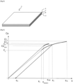
- a device according to the invention of the type represented on the figure 1 comprises a sensor 2 and a target part 10, on which the sensor 2 is fixed.
- the target part 10 may in particular be a fragile part.
- the target part 10 may be made of a ceramic and/or a glass and/or a glass ceramic and/or a ceramic phase composite (CMC), the melting temperature of which is preferably greater than 1,000°C, or even above 1,200°C.
- the target part may be made of one or more of the following materials: alumina, zirconia, silica, silicon or boron carbide, and silicon nitride.
- the target part 10 can be made of a molten or sintered material.
- the target part consists of more than 80%, more than 90%, or even substantially 100% of its mass, of ceramic grains, preferably agglomerated by sintering.
- the target part 10 may have a mass greater than 500 g, preferably greater than 1 kg and/or less than 100 kg, less than 50 kg, less than 10 kg, or even less than 5 kg.
- the target part 10 can have any shape, determined according to the intended application.
- the target part 10 may in particular have the shape of a rectangular parallelepiped brick. It can be in the form of a cylinder, a roller or a rod, a hollow part or one having a closed or open internal cavity, for example a crucible, an open tube of a or on each side, a disc or a flat cylinder pierced, in particular with a central orifice. It may in particular be in the form of a plate or a disk whose thickness is greater than 5 mm, preferably greater than 10 mm and/or less than 20 mm.
- the target part preferably has a length greater than 20 cm and/or less than 50 cm, and/or a width greater than 10 cm and/or less than 30 cm, and/or a thickness greater than 1 cm and/or less than 5 cm.
- the target part preferably has a length greater than 50 cm and/or less than 200 cm, a width greater than 30 cm and/or less than 50 cm and a thickness greater than 3 mm. and/or less than 10 cm.
- the target part preferably has a length greater than 20 cm and/or less than 200 cm, and/or a width greater than 20 cm and/or less than 70 cm, and/or a thickness greater than 3, preferably greater than 5 mm and/or less than 5 cm.
- the target part may have a diameter greater than 20 cm and a width greater than 1 mm or more (abrasive disc), or even greater than 10 mm, or even greater than 100 mm (abrasive wheel).
- the senor is arranged so as not to be directly subjected to the stresses applied to the target part.
- the target part is a cooking plate
- the sensor is preferably not in direct contact with the material to be cooked which is placed on the cooking plate.
- the senor must be arranged so as to undergo, at least indirectly, constraints applied to the target part.
- the sensor can be placed on the surface and/or in the mass of the target part.
- the surface of the target part on which the sensor 2 is fixed can be any surface of the target part 10.
- this surface is a surface which, in service, is likely to undergo mechanical or thermomechanical stress capable of degrading the target part.
- these stresses can result from high temperatures, temperature variations or mechanical shocks.
- the shape of the surface on which the sensor is fixed is not limiting. It can be smooth or rough, have through holes or be continuous, optionally have cavities or bosses, be developable or not, be flat or not.
- the ceramic particles and/or the conductive particles forming the conductive network are distributed in the target part, preferably in the form of one or more ceramic layers, on the surface and/or within the target part. , preferably in a binder phase binding grains of the target part or on the surface of open pores of the target part.
- a kit according to the invention comprises a device according to the invention and a measuring device 16 adapted to measure said electrical property, in particular in step 3).
- the measuring device 16 can be connected to the conductive network 7 by means of cables, for example connecting it to the connection terminals 18 ( figure 1 ).
- the cables and connection terminals are made of a refractory metal resistant to more than 400°C, for example Platinum.
- a refractory and conductive platinum-based glue can be used to improve electrical contacts.
- the measuring device 16 is not connected to the conductive network 7.
- the latter forms a loop allowing contactless measurement, by induction.
- the measuring device 16 is connected to an analysis device 22, that is to say a device conventionally comprising a processor, a computer memory and software configured to determine, from the measured electrical property, a state of the room.
- an analysis device 22 that is to say a device conventionally comprising a processor, a computer memory and software configured to determine, from the measured electrical property, a state of the room.
- the measuring device 16 can alternatively be physically integrated into the analysis device.
- any conventional measuring and analysis device can be used.
- the processing, analysis and recording of the measured electrical property and its variations can use means of amplification, filtering, multiplexing and digitization known to those skilled in the art in the field of resistive sensors, in particular resistive composite sensors.
- Communication between the sensor and the measuring device and/or between the measuring device and the analysis device can be carried out wired or wirelessly, for example by wifi or Bluetooth® .
- the measuring device is programmed to record the impedance of the sensor at regular time intervals.
- a sensor according to the invention intended to constitute, with a target part, a device according to the invention, is manufactured according to a method comprising steps a) to d).
- step a) we prepare a starting load.
- the quantities of ceramic particles and/or precursors of ceramic particles and of conductive particles and/or precursors of conductive particles in the slip are determined so that the slip leads, after step c), to a microstructure consisting of conductive particles dispersed in a ceramic phase.
- more than 90%, preferably more than 95%, preferably 100% of the particles dispersed in the solvent, in percentage by number are ceramic particles and/or precursors of ceramic particles, and/or conductive particles and/or conductive particle precursors.
- the conductive particles may be composite particles comprising a non-conductive central core and an electrically conductive coating deposited on this central core.
- the central core may in particular be a fiber, preferably made of a ceramic material, in particular a crystallized material, a glass ceramic or a glass.
- the central core may in particular be a silica fiber obtained by fusing quartz.
- the fiber may for example have a diameter or thickness less than 20,000 nanometers, preferably less than 18,000 nanometers, preferably less than or equal to 16,000 nanometers, preferably less than 15,000 nanometers, preferably less than 14,000 nanometers, or even less than 12,000 nanometers, or less than 10,000 nanometers.
- a precursor of a metal is deposited on the central core, for example an inorganic metal salt or an organometallic compound, or a sol-gel route is used from an alkoxide, then an alkoxide is then carried out. reduction to the elemental state of the metal, for example by heat treatment or chemical reaction with a reducing agent.
- organometallic compounds Dimethyl[tris(dimethylamino)titanio]amine, a Zirconium borohydride, a tungsten poly
- the metal is chosen from the group formed by Ag, Al, Au, Cu, Fe, Ge, Mo, Ni, Pd, Pt, Rh, Si, Ta, Ti, W and their alloys.
- an organic salt which is soluble in water and which dissociates to form a free cation is deposited.
- the deposition can be in particular by spraying, by dipping, by impregnation or in the gas phase.
- conductive nanoparticles on the central core, for example by chemisorption after silanization of the central core, by physisorption or by electrostatic attraction.
- the starting charge can take the form (a2) of a “ceramic” slip comprising ceramic particles and/or ceramic particle precursors and a first solvent, and a “conductive” slip comprising electrically conductive particles and a second solvent , preferably identical to the first solvent.
- more than 90%, preferably more than 95%, preferably 100% of the particles dispersed in the first solvent, in percentage by number, are ceramic particles and/or precursors of ceramic particles.
- more than 90%, preferably more than 95%, preferably 100% of the particles dispersed in the second solvent, in percentage by number, are conductive particles and/or precursors of conductive particles.
- the precursors of ceramic particles may in particular be chosen from pre-ceramic polymers which, during heat treatment, decompose into ceramic particles, for example being a polysiloxane, a polysilaxane, a polycarboxylane, a TetraEthylOrthoSilicate, a silicone-based polymer, or a polymer based on Polyvinylpyrolidone.
- organometallic compounds or precursors of conductive ceramic particles chosen for example from Dimethyl[tris(dimethyla
- the quantity of conductive particles is preferably between 0.1 and 30%, preferably between 0.1% and 10% by volume, based on the volume of the slip.
- the solvent may be aqueous or non-aqueous. It is preferably organic, in particular for dispersing metal particles. Preferably the solvent is isopropanol.
- the solvent may be a carboxylic acid, for example oleic acid, a propionic acid or a coprylic acid, water with an ammonium tetraethyl, a PolylminoEthylene ( PEI), 2-butanone/ethanol or C 57 H 105 O 12 P or “Castor oil phosphate”.
- a carboxylic acid for example oleic acid, a propionic acid or a coprylic acid
- water with an ammonium tetraethyl a PolylminoEthylene ( PEI), 2-butanone/ethanol or C 57 H 105 O 12 P or “Castor oil phosphate”.
- the dry matter content in a slip is preferably greater than 20%, preferably greater than 30%, preferably greater than 50%.
- the mixing of particles in a solvent can be carried out by any means, preferably with a mechanical stirrer, an ultrasound-assisted mechanical stirrer, an ultra turrax ® , or by acoustic resonance.
- particle dispersion can be controlled by ultrasound and/or acoustic resonance.
- the starting charge can take the form (a3) of a powder comprising a mixture of ceramic particles and/or ceramic particle precursors, and conductive particles.
- more than 90%, preferably more than 95%, preferably 100% of the particles of the powder, in percentage by number are ceramic particles and/or precursors of ceramic particles, and/or conductive particles and /or precursors of conductive particles.
- the starting charge can take the form (a4) of at least two different powders, a first powder comprising, preferably consisting of ceramic particles and/or precursors of ceramic particles, a second powder comprising, preferably consisting of conductive particles.
- more than 90%, preferably more than 95%, preferably 100% of the particles of the first powder, in percentage by number are ceramic particles and/or precursors of ceramic particles.
- more than 90%, preferably more than 95%, preferably 100% of the particles of the second powder, in percentage by number, are conductive particles and/or precursors of conductive particles.
- the starting charge can be a first powder consisting of ceramic particles and/or precursors of ceramic particles to constitute certain layers, called “ceramic layers”, and a second powder made up of conductive particles to constitute other layers, called “conductive layers”.
- the substrate on which the starting charge is deposited or integrated in step b) constitutes the ceramic phase or is a precursor of the ceramic phase, that is to say it transforms into the ceramic phase in step c), preferably by sintering. It is then not necessary for the starting charge to provide ceramic particles or precursors of ceramic particles.
- the starting charge can thus take the form (a5) of a “conductive” slip comprising conductive particles, preferably metallic, and/or precursors of conductive particles or the form (a6) of a “conductive” powder comprising conductive particles and/or conductive particle precursors.
- a “conductive” slip comprising conductive particles, preferably metallic, and/or precursors of conductive particles
- a “conductive” powder comprising conductive particles and/or conductive particle precursors.
- the starting charge takes the form (a7) of a “functionalized” slip or the form (a8) of a “functionalized” powder comprising ceramic particles and/or precursors of ceramic particles on which conductive particles and/or precursors of conductive particles are attached.
- the ceramic particles may in particular be platelets, for example made of alumina, alpha-SiC or AIN.
- more than 90%, preferably more than 95%, preferably more than 98%, preferably more than 99%, by volume, of the platelets have a length of less than 150 ⁇ m, preferably less than 100 ⁇ m, and /or preferably greater than 5 ⁇ m, preferably greater than 10 ⁇ m.
- more than 90%, preferably more than 95%, preferably more than 98%, preferably more than 99%, by volume, of the platelets have an aspect ratio (ratio of the length to the thickness of the wafer) less than 70, preferably less than 50, and/or preferably greater than 10, preferably greater than 15, preferably greater than 20.
- Shapes (a7) and (a8) advantageously make it possible to manufacture a target part in which the sensor is integrated, for example as described in PCT/IB2013/060700.
- the conductive particles may in particular be made of a metal chosen from Ag, Cu, Pt and Fe.
- step b) the starting charge is put in the form of a preform.
- a first variant (b1) consists of depositing the starting charge on a substrate.
- the substrate is the target part or a raw part of the target part, and it is porous or fibrous, for example when the substrate is a felt or a woven, knitted, or braided textile, it is preferable to form the sensor by depositing one or more layers directly on the target part or the green part of the target part, or in the porosity of the target part or the green part of the target part.
- the sintering temperature of the green part is preferably lower than the consolidation temperature of the preform.
- the substrate has the form of a thread or a textile.
- a treatment is preferably applied to fix the conductive particles and/or the precursors of conductive particles contained in the starting charge, conventionally by drying. We thus obtain a yarn or a textile according to the invention.
- Functionalized threads can then be arranged in the form of a textile, without preferential orientation, for example to constitute a felt, or according to at least one preferential orientation, for example by weaving, knitting, braiding or sewing, to constitute all or part of the target part or a raw part of the target part.
- the functionalized yarns represent more than 5%, more than 10% and/or less than 90%, less than 80% of the mass of the textile.
- functionalized yarns are preferably distributed homogeneously.
- the substrate is preferably the target part.
- the manufacturing of the latter, and in particular the sintering operation of the possible raw part, does not risk damaging the sensor.
- the target part is preferably a porous body having an open porosity greater than 1%, 3%, 5% or 10%, preferably an open porosity oriented along a plane or a preferential direction.
- the precision of the sensor is advantageously improved along one or more directions of deformation.
- the dimensions and/or orientation of the pores are determined as a function of the deformation behavior desired for the sensor.
- the target part is a product, preferably sintered, comprising a plurality of frustoconical tubular pores, preferably macroscopic, preferably oriented in a preferred direction.
- the target part conforms to the teaching of PCT/IB2013/060700.
- the substrate is a hand-flexible substrate, for example of the Flexiramics type manufactured by the company Eurekite, or a Nextel fabric.
- the starting charge is preferably deposited on the substrate in any form, provided that it is suitable for the intended application.
- the shaped starting charge can be massive. It may have a thickness greater than 1 mm, 5 mm or 10 mm and/or less than 20 mm.
- the starting charge is preferably deposited on the substrate in the form of one, two or more two layers.
- the successive layers may be identical or different.
- a ceramic layer that is to say a layer which comprises ceramic particles and/or precursors of ceramic particles but not conductive particles or precursors of conductive particles, succeeds a conductive layer, this is that is to say a layer which contains conductive particles but not ceramic particles or ceramic particle precursors, and/or a conductive layer follows a ceramic layer.
- the layer(s) can be deposited by impregnation of the target part.
- the deposition of a layer can be carried out by strip casting or by spraying, preferably by strip casting.
- the thickness of the layer is preferably between 0.05 mm and 3 mm, preferably between 0.1 mm and 1 mm.
- an electric or magnetic field is applied to orient and/or disperse the conductive particles.
- the electrical property can thus be different depending on the stress experienced by the sensor.
- Tape casting is particularly suitable, preferably using electrophoresis or chemophoresis techniques to control the structure and orientation of the conductive particles during shaping. Spraying the starting charge, preferably at room temperature, typically around 20°C, is also effective.
- the second variant (b2) consists of incorporating the starting charge into the mass of the substrate.
- the starting load is incorporated within the raw part of the target part or within the target part.
- Step c) then leads directly to a device according to the invention.
- conductive particles preferably in the form of fibers (or a precursor of said conductive particles), are introduced into a wire also comprising non-conductive particles, preferably in the form of fibers.
- a wire also comprising non-conductive particles, preferably in the form of fibers.
- Functionalized threads can then be arranged in the form of a textile, without preferential orientation, for example to constitute a felt, or according to at least one preferential orientation, for example by weaving, knitting, braiding or sewing, to constitute all or part of the target part or a raw part of the target part.
- the functionalized yarns represent more than 5%, more than 10% and/or less than 90%, less than 80% of the mass of the textile.
- functionalized yarns are preferably distributed homogeneously.
- the starting load is shaped so as to constitute a raw part of the target part.
- the device according to the invention merges with the sensor according to the invention, the target part constituting the sensor.
- the starting charge can in particular be configured for the manufacture of a porous body, for example such as that described in PCT/IB2013/060700. It may contain colloidal silica to facilitate possible sintering.
- the starting charge can in particular be in the form (a1), (a3), (a7) or (a8).
- the elongated conductive particles and/or the fine ceramic particles are oriented in a preferred direction or plane, preferably a preferred direction.
- the orientation of particles can for example be modified magnetically or by a freeze casting process, as described for example in PCT/IB2013/060700.
- the anisotropic (non-spherical) shape of a particle for example a platelet or rod or grain of rice shape, or a multi-faceted shape, can favor its preferential orientation. A simple test allows you to check whether a particle is orientable.
- the starting charge after shaping comprises a liquid phase
- it is then dried, preferably at a temperature below 100°C, preferably less than 80°C, preferably for a period of more than 2 hours, preferably more than 4 hours.
- each deposited layer can be dried before depositing the next layer.
- step c) the preform obtained in step b) is consolidated by heat treatment.
- the metal ions can be reduced chemically at less than 100°C, as described for example in US5681617A .
- the starting charge is deposited on a substrate which is intended to be consolidated.
- the starting charge is incorporated into the mass of a substrate which is intended to be consolidated.
- the heat treatment is preferably adapted to simultaneously consolidate the preform and the substrate.
- This embodiment is particularly advantageous when the substrate is a green part intended to be sintered to constitute the target part, and in particular when the difference between the sintering temperature of the green part and the sintering temperature of the preform is less than 50°C.
- consolidation can be carried out after each deposition of a layer or for all layers simultaneously.
- the consolidation is preferably carried out, in a conventional manner, under a controlled oxidizing, neutral or reducing atmosphere, depending on the desired ceramic phase, preferably under a non-oxidizing atmosphere if the ceramic particles are made of a non-oxide material.
- Consolidation may be sintering.
- Sintering can be carried out in air, in particular if the preform is made of a material with oriented porosity of the oxide type. Sintering can be carried out in a non-oxidizing atmosphere, in particular if the preform is made of a non-oxide material.
- Sintering can preferably be carried out without pressure, in particular if the preform is made of a material with oriented porosity.
- Sintering can be carried out under pressure, preferably by SPS ( “Spark Plasma Sintering” in English).
- Sintering can also be carried out using a hot pressing process.
- Sintering can be carried out at a temperature lower than 1600°C, lower than 1500°C, lower than 1400°C, lower than 1200°C, or even lower than 1000°C.
- the sintering time is preferably less than one hour, which limits the migration and agglomeration of the conductive particles, and thus improves the sensitivity of the sensor.
- the sintering can be hydrothermal or solvothermal sintering, of the type introduced in 1972 by D.M. Roy et al.
- the thermal consolidation by sintering is carried out under a controlled inert or reducing atmosphere, at a temperature below 1600°C, preferably less than 1500°C, preferably less than 1400°C, with a stage at the sintering temperature lasting less than 4 hours, preferably less than 2 hours, or even less than one hour.
- the cooking can be for example rHLPD densification ( “reactive Hydrothermal Liquid Phase densification” , in English), developed by Riman of Rutgers University or CSP (“ coldsintering process” in English), developed at the State University from Pennsylvania in the group of Professor Clive A. Randall.
- rHLPD densification “reactive Hydrothermal Liquid Phase densification” , in English
- CSP coldsintering process
- Step c) leads to a measurement mass comprising a conductive network of conductive particles and a ceramic phase, preferably electrically insulating, preferably covering or coating the conductive network.
- step d) the measuring mass resulting from the consolidation of the preform can be fixed on a support.
- the substrate can serve as a support.
- step c) does not lead to a device according to the invention, but to an independent sensor of the target part.
- the support can facilitate the handling of the sensor, but also serve to modify its deformation behavior, in particular so that it is adapted to the deformations of the target part.
- step c) leads to the manufacture of the sensor and of the target part, which merge. No support is therefore required.
- the substrate is temporary, it can be separated from the preform after drying or separated from the measuring mass after consolidation.
- An interfacing layer 9 can be added to the sensor, so as to be interposed between the target part and the other elements of the sensor. In particular, it can be interposed between the support 8 and the target part 10, or, in the absence of support, between the measuring mass and the target part 10.
- step e) fixing the sensor on the target part 10, so as to constitute a device according to the invention, for example of the type shown on the figure 2 .
- the interfacing layer 9 can be an adhesive allowing this fixing.
- this glue is dried before using the target part. It is preferably subjected to cooking in order to be consolidated, preferably at a temperature lower than the consolidation temperature of the measuring mass in step c).
- Step e) is particularly well suited when the target part is a fabric or a part having a porous or fibrous texture, for example a fabric of glass fibers and/or fibers made of a non-metallic inorganic material and at least partially crystallized .
- step 1) a device according to the invention is manufactured, for example by fixing a sensor 2 on a target part 10 as shown in the figure 1 .
- step 2) the device is calibrated, that is to say a calibration curve 24 or 24' is determined providing, for each possible response M of the sensor 2, information on the physical state of the part, and in particular on the damage E, and preferably information on the extent of the damage.
- the determination of the calibration curve is preferably carried out at a reference time prior to the first commissioning of the device according to the invention.
- the measurements of the responses M are preferably carried out at a temperature substantially equal to the operating temperature at which the target part is intended to be used.
- the calibration is carried out on test devices identical to the device according to the invention and which, each, undergo a particular constraint. We then observe possible damage to the part. Preferably, any damage is measured, preferably without contact, preferably by means of X-rays, ultrasound or a resonance method.
- Fatigue of the target part leads to fatigue of the conductive network which can be measured by the evolution of the measured electrical property.
- the calibration curve thus makes it possible to establish a relationship between a response M and the amplitude of fatigue, even in the absence of perceptible deformation of the target part or the sensor.
- step 3 we interrogate, at the updated instant and with the measuring device 16, the sensor 2, to measure said electrical property and we deduce information on the state of the target part.
- the time interval between the calibration instant and the updated instant may for example be greater than one week, two weeks, one month, two months and/or less than one year, or six months.
- the two cables of the measuring device 16 are conventionally connected to the connection terminals 18 ( figure 1 ).
- connection of the measuring device to the connection terminals can be deactivated, which is particularly useful when checking the target part is carried out on an ad hoc basis. It can be non-deactivatable, that is to say permanent, in particular when the control is substantially continuous.
- the measurement of said electrical property is carried out without contact with the sensor.
- the electrical property may be inductance, which can be conventionally measured remotely.
- the response M provided by the sensor may depend on its level of deformation or its state of fatigue.
- the shape and length of the conductive particles of the sensor according to the invention make it possible to detect very small tension and compression deformations which appear on the target part during the damage phase, as well as than measuring the state of fatigue.
- the ceramic phase which protects the conductive network, also allows the sensor to operate at high temperatures, preferably without additional cooling device.
- the response M of the sensor is then analyzed by the analysis device 22, connected to the measuring device 16, preferably in order to provide information on the damage possible of the room. More precisely, the analysis device uses the calibration curve 24 or 24' to determine information on the damage E of the target part.
- the state of the target part is considered different depending on whether the measured value is greater than or less than a threshold value which corresponds to a predetermined constraint for the target part, or “threshold constraint”.
- the threshold value can be determined so that beyond the threshold value, the risk of rupture exists or damage becomes unacceptable. In this case, the condition of the target part is considered “unsatisfactory”. Otherwise, it is considered “satisfactory”.
- the threshold value depends on the target part, in particular its geometry and the material it is made from, but also the applications and conditions of use envisaged.
- the threshold constraint can be determined by carrying out a test setup consisting of a target part with a sensor and by measuring the effect of different stresses applied to the target part under similar conditions of use, particularly in temperature, to those in the targeted application. It is thus possible to know the threshold value corresponding to the threshold constraint.
- the threshold value can be the measurement for which the stress applied to the target part leads to the beginning of cracking or leads to damage such that its use becomes dangerous or risky.
- the threshold stress may in particular be the stress applied to the target part beyond which the deformation of the target part is no longer elastic and becomes plastic.
- the threshold value that is to say the electrical property measured when the threshold stress is applied, is preferably greater than 100 times, or even 1000 times the electrical property measured without the application of stress, at the same temperature .
- the calibration curve advantageously makes it possible to evaluate the level of damage.
- the condition of the part can for example be described as “slightly cracked”, “moderately cracked” or “heavily cracked”, depending on the value of the electrical property measured.
- the threshold value can also be the electrical property beyond which the use of the target part becomes dangerous or risky.
- the calibration curve 24' can also be used to provide an evaluation at any time of the state of fatigue of the target part.
- the physical states determined according to the invention are processed statistically, for example by means of artificial intelligence algorithms, so as to improve decision-making.
- FIG 4 illustrates the deformation ⁇ of the target part (solid line) and of the conductive network of the sensor (dotted line) of a device according to the invention, as a function of the stress Ca applied to the target part.
- the sensor fixed on the fragile part is configured to deform plastically under the effect of at least one stress applied to the fragile part and leading to damage to the fragile part.
- the constraint is applied by projecting a projectile onto the target part.
- the Ca stress (expressed in MPa or N/mm 2 ) can be estimated by the product m ⁇ A / S, m being expressed in Kg, A in m/s 2 and S in mm 2 .
- the mass of the projectile is determined using a precision milligram balance.
- the impact surface is measured using a ruler on the part after impact and corresponds to the mark left by the projectile on the aramid textile covering. When this is not visible, before the projection stage, the envelope is marked with graduations so as to precisely determine (to the nearest mm) the impact surface using a high-speed camera.
- Acceleration is measured by an accelerometer consisting of a cell stuck to the front face, or “impact face,” of the sample. This is preferably glued at a distance of 100 mm from the point of impact.
- Cr M designates the rupture stress of the target part and ⁇ rM designates the maximum deformation, corresponding to the rupture of the target part.
- This min or “minimum damage stress” of the target part is the smallest stress applied to the target part and leading to damage of the target part by microcracking.
- Ce min the stresses greater than or equal to Ce min leading to damage of the target part, in the form of 'microcracking.
- Cr c designates the stress applied to the target part and which leads to the rupture of the sensor. (In practice, breakage of the target part can lead to breakage of the sensor).
- ⁇ rC designates the maximum deformation of the sensor, corresponding to its rupture (assuming that the rupture of the target part did not damage the sensor).
- Cs denotes the threshold stress, the deformation of the sensor being elastic or plastic depending on whether the stress applied to the target part is less than or greater than or equal to Cs, respectively.
- ⁇ s denotes the deformation when the threshold stress is applied.
- the plastic deformation of the target part only occurs when the sensor itself undergoes plastic deformation. Any damage to the target part is then memorized by the sensor.
- the minimum damage stress of the target part Ce min is less than the stress Cr c applied to the target part and which leads to the sensor breaking.
- the plastic deformation of the sensor begins while the target part is still in elastic deformation.
- the strain sensor can thus memorize a high stress which has not, however, led to damage to the target part.
- the plastic deformation range of the sensor ends after the target part has failed.
- the deformation sensor can thus memorize any stress that has led to damage to the target part.
- the deformation of sensor 2 is plastic when the stress applied to the target part reaches Ce min and the target part begins to degrade. This plastic deformation of the sensor makes it possible, if the stress ceases, to keep a trace that stresses leading to damage to the target part have been reached.
- the stress continues to increase, it causes plastic deformation of the target part, in addition to plastic deformation of the sensor. For example, it reaches the stress C 1 , corresponding to the deformation ⁇ 1 .
- this plastic deformation results in a residual deformation ⁇ 2 of the sensor, which thus memorizes the application of the maximum stress C 1 applied to the target part.
- the arrow illustrates the deformation of the sensor when the stress ceases after reaching C 1 , greater than Ce min , and shows that the plasticity of the sensor has memorized the damage of the target part.
- the threshold constraint which corresponds to the plasticity limit of the sensor, is less than or equal to the minimum damage constraint Ce min , that is to say that Cs ⁇ Ce min .
- Any Ca stress applied to the target part and which constitutes a damage stress producing microcracking, that is to say greater than the minimum damage stress Ce min therefore produces a plastic deformation of the sensor. In other words, plastic deformation of the target part only occurs when the sensor itself undergoes plastic deformation.
- the sensor In the event of application of a stress Ca greater than or equal to the minimum damage stress, the sensor, and more precisely the conductive network, is therefore plastically deformed, and thus retains a “physical memory” of this application.
- the electrical property of the conductive network in particular its electrical resistance, is variable depending on the geometry and/or structure of the conductive network.
- the plastic deformation of the conductive network permanently modifies the resistance of the conductive network. The sensor thus makes it possible to detect, by means of the calibration curve, that a damage constraint has been applied, and therefore that the target part is microcracked.
- measuring the plastic deformation advantageously makes it possible to evaluate the extent of the damage stress, and therefore of the microcracking of the target part.
- the plastic deformation domain of the sensor begins while the target part is still in elastic deformation.
- the strain sensor can thus memorize a high stress that has not led to damage to the target part.
- the sensor deforms elastically when the stress applied to the target part is not close to the minimum damage stress, that is to say typically during normal operation of the target part.
- the threshold stress be as close as possible to the minimum damage stress.
- the tolerance ( Ce min - Cs) / Cs depends on the intended application.
- the senor is configured not to be destroyed by the application of any stress to the target part which does not lead to rupture of the target part.
- the sensor remains operational as long as the stress applied to the target part does not lead to the breakage of the target part.
- the plastic deformation domain of the sensor ends after the ceramic part has broken. The deformation sensor can thus memorize any stress that has led to damage to the target part.
- the example above requires choosing a material for the ceramic phase which has a domain of elastic deformation more limited than that of the material of the target part and which, preferably presents a plastic domain which extends beyond that of the material of the target part.
- the senor is chosen so as to break under the effect of a stress Cs' applied to the target part less than the stress Cr leading to the rupture of the target part, preferably less than Ce min .
- the breakage of the sensor thus leads to an alert, in “all or nothing” mode, and triggers, for example, an alarm to stop using the target room.
- a sensor in the form of a patch is fixed on a SiC ceramic plate using a layer of epoxy-based thermosetting glue.
- the thickness of the glue layer is substantially constant and less than 0.5 mm.
- the device thus manufactured is calibrated, as described above, by applying repeated stresses, but which do not lead to microcracking. We thus establish a calibration curve making it possible to evaluate the state of fatigue of the part, of the type of curve 24'.
- the evolution of the electrical property, in this case the electrical resistance of the conductive network, is more progressive than during the detection of microcracks, which quickly lead to the destruction of the target part.
- the ceramic tiles are conventionally positioned on the walls of the combustion chamber. These tiles are subjected to a strong thermal gradient (around 1500°C on the hot side and around 600°C on the opposite cold side, oriented towards the combustion chamber). The sudden deterioration of a tile can have serious consequences, particularly if tile debris damages one of the turbine blades.
- a starting charge is prepared in the form of a slip in which alumina particles having a length of approximately 1 micron, and conductive particles, in the form of Platinum (Pt) fibers of 100 nanometers, of the type those described in WO2010003389A2 , are mixed in isopropanol.
- the composition of the slip, in volume percentages, is preferably as follows: 15% platinum fibers, 30% alumina particles, and 55% solvent and shaping additives.
- the alumina particles are replaced by SiC or BN particles.
- the Platinum (Pt) fibers are replaced by carbon nanotubes.
- a film of the slip is deposited by casting on a tile manufactured for example according to the teaching of WO2015011623A1 , then dried at 110°C to obtain a film with an average thickness of approximately 500 ⁇ m.
- the conductive particles are coated in the ceramic phase.
- Platinum wires are connected to each end of the conductive network, so as to allow an electrical connection to an Ohm meter.
- the sensor is then fixed to the cold face of a ceramic tile of a gas turbine, preferably by ceramic bonding or mechanical adhesion.
- the sensor can in particular be fixed using Pyro-Putty #653 high temperature ceramic glue supplied by Aremco.
- the precision of the sensor makes it possible to detect small variations in the electrical resistance of the conductive network, and therefore to anticipate the occurrence of harmful phenomena.
- a sensor according to the invention in the form of a patch, is stuck to the surface of a cooking support.
- the electrical resistance of the conductive network is measured between two connection points. We see that the electrical resistance increases, probably as a result of the progressive breakdown of “bridges” between the conductive particles. Measuring the resistance thus advantageously makes it possible to estimate the fatigue of the target part.
- Measuring the electrical property of the sensor, preferably the electrical resistance of the conductive network, is also useful for evaluating the wear of an abrasive wheel.
- a sensor can be placed on the surface of an abrasive wheel, preferably in the form of a patch stuck to the side of the wheel, preferably perpendicular to the working surface of the wheel.
- the sensor is preferably “integrated” into the target room.
- the ceramic particles of the sensor may be abrasive grains of the grinding wheel or, preferably, be dispersed in all or part of the matrix which binds the abrasive grains of the grinding wheel, in particular when the abrasive grains are too large to constitute fine ceramic particles.
- the sensor can thus be used to measure the progressive reduction in the volume of the grinding wheel during its use, and to assess its integrity. This information advantageously makes it possible to optimally manage the use and replacement of the grinding wheel.
- Conductive particles and/or precursors of such particles are incorporated into a ceramic non-woven fabric or into a ceramic woven fabric made up of ceramic fibers, preferably oriented in a preferred plane, preferably in a preferred direction.
- the conductive particles are preferably manufactured by functionalization of ceramic fibers, identical to or different from the ceramic fibers which constitute the ceramic nonwoven.
- the functionalization methods described above can be implemented for this purpose.
- the incorporation of the conductive particles can be carried out by strip casting, by pressing or by layer deposition.
- the structure consisting of the ceramic nonwoven in which the conductive particles have been incorporated is then sintered, preferably until an open porosity of less than 10%, preferably less than 5%, and preferably greater than 1 is obtained. %.
- Alumina platelets having a length between 10 and 100 ⁇ m and an aspect ratio between 20 and 50, and conductive particles made of a metal chosen from Ag, Cu, Pt and Fe are dispersed in isopropanol to make a slip.
- Precursors of the conductive particles can be used to replace, at least in part, the conductive particles. They are then reduced to be transformed into so-called conductive particles.
- the slip is cast in strips (“tape casting”), in the classic manner.
- the thickness of the strip is preferably between 100 and 600 micrometers so as to orient the platelets.
- the strip is then preferably sintered until an open porosity of less than 10%, preferably less than 5%, and preferably greater than 1% is obtained.
- the conductive particles create a conductive network oriented preferentially parallel to the platelets.
- a sintered porous body is manufactured following the teaching of PCT/IB2013/060700.
- the porous body preferably has a volume porosity of between 30% and 70%, preferably between 40% and 60%.
- the porous body has substantially parallel tubular pores.
- the wafers used may in particular be alumina, alpha-SiC or AIN wafers. They preferably have a length of between 10 and 100 ⁇ m and an aspect ratio of between 20 and 50.
- the porous body is then impregnated with a slip consisting of conductive particles, preferably metallic, suspended in a solvent (form (a5)).
- a slip consisting of conductive particles, preferably metallic, suspended in a solvent (form (a5)).
- the quantity of conductive particles is adapted to obtain, after drying, a conductive network whose electrical resistance can be modified by deformation and/or fatigue.
- the length of the conductive particles is less than 1 ⁇ m, preferably less than or equal to 100 nm.
- the impregnation can be carried out under vacuum or, more generally, by creating a pressure gradient favoring the penetration of the slip into the tubular pores.
- the deposition of conductive particles can also be carried out by spraying the slip, preferably at room temperature.
- the deposition of conductive particles can also be carried out by infiltration of the slip, preferably under a residual pressure less than or equal to 0.1 bar, preferably at room temperature.
- the viscosity of the slip measured at room temperature, is preferably between 0.5 and 20 centipoises.
- the infiltration time is preferably 5 minutes to a few hours, depending on the thickness of the porous body.
- the slip is preferably a colloidal solution.
- the porous body can be replaced by the raw body which, by sintering, leads to the porous body.
- the conductive particles can be replaced by conductive particle precursors, which are then reduced to the form of metallic conductive particles.
- a mixture of metal ions and a chemical reducing agent can be deposited by the “electroless” method, the metal ion, as described for example in US5681617A , preferably at less than 100°C, preferably at room temperature.
- a catalyst, particularly a catalytic metal, can be added to the mixture to accelerate the transformation of the conductive particle precursors into conductive particles.
- the porous body can be functionalized with a thiol or a silane.
- the silane may have a polar group such as an amine, phosphonate, sulphonate or carboxylate group.
- a conductive network is obtained which extends to the surface of the pores.
- This conductive network is advantageously protected by the porous body. It is also advantageously preferentially oriented because it relies on preferentially oriented pores.
- the impregnation or percolation can be total or, preferably partial, so as to dimension the conductive network as desired.
- a layer of ceramic particles forming a ceramic phase is preferably deposited above said conductive particles or said precursors of the conductive particles.
- this layer insulates electrically and protects physically.
- the process is adapted so that the residual open porosity of the porous body thus obtained, which constitutes a sensor according to the invention, is between 1 and 10% by volume.
- this sensor has a range of plastic deformability.
- a metallic film preferably made of a metal chosen from Cu, Au, Pt, Pd, Ag, Sn, Al, Ni, Pb, Zn and their alloys, can be produced by metallization/spraying on the surface of the porous body and in contact with the conductive network.
- the conductive particles are mixed with the alumina platelets before forming the porous body.
- they represent more than 10% by weight of the particles, the remaining 100% being constituted by alumina platelets.
- composite fibers are first manufactured, each comprising a central core coated at least partially with an electrically conductive coating.
- Each core preferably made of glass, preferably of silica, has an aspect ratio of between 2 and 20,0000, and a length of between 5 mm and 5 m.
- the cores are obtained by spinning from a mixture of molten silica, preferably obtained by melting quartz.
- a solution comprising metal salts (precursors of conductive particles) is applied to the surface of the cores by electrodeposition.
- the cores coated with the solution are then dried, so as to harden the coating and obtain conductive particles in the form of composite fibers.
- the conductive particles are then incorporated into the manufacture of wires, by mixing with the other constituents of the wires before being assembled to form these wires.
- the conductive particles preferably represent more than 10% of the mass of the wires.
- the conductive particles are substantially uniformly distributed in said first functionalized wires.
- conductive particles are placed on wires, in one piece or preferably each made up of an assembly of several hundred filaments.
- the wires are made of glass, preferably silica.
- conductive particles constituting third wires may be used.
- the first and/or second wires and/or third wires preferably have a length of between 5 cm and 5 km, preferably between 5 cm and 5 m.
- the first and/or second and/or third wires, and optionally fourth wires not carrying conductive particles, preferably made of glass, preferably made of silica, are preferably used to manufacture a textile, preferably in the form of a felt, a sheet of parallel threads, a woven fabric or a knitted fabric, or an assembly of one or more said felts, layers, woven fabrics or knitted fabrics. Conventional manufacturing techniques can be used.
- the first and/or second and/or third threads, and optionally fourth threads can be mixed, so as to form a felt.
- the mixed yarns then preferably have a length of between 5 cm and 5 km, preferably between 5 cm and 5 m.
- first and/or second and/or third wires can be arranged parallel to each other in the form of a layer or of several layers.
- the tablecloths can then be assembled together, for example sewn to each other.
- the orientation of the wires of two successive layers is preferably different.
- the first and/or second and/or third yarns, and optionally fourth yarns can be arranged further knitted or woven in the form of a knitted or woven fabric.
- Several knits and/or woven fabrics thus manufactured can be superimposed and assembled, for example sewn.
- Intermediate textile layers devoid of conductive particles can be interposed between two said knitted and/or woven fabrics.
- the orientation of the threads of two successive knitted and/or woven and/or intermediate layers is preferably different.
- An intermediate layer may for example be a non-woven, woven or knitted fabric, formed with fourth threads.
- fourth wires are arranged between first and/or second and/or third wires.
- a textile preferably in the form of a felt, a sheet of parallel threads, a woven or knitted fabric, or an assembly of one or more said felts , tablecloths, woven or knitted, is made with fourth yarns, devoid of conductive particles.
- Conventional manufacturing techniques can be used.
- the conductive particles are placed on the fourth wires, preferably by impregnation with a slip containing the conductive particles or precursors of conductive particles.
- conductive particles can be placed on the surface of a textile comprising first and/or second threads.
- the invention is advantageously applicable for target parts of any geometry. Furthermore, the invention does not significantly modify the size of these parts.
- the invention makes it possible to detect deformations of small amplitudes, the sensor being very sensitive. It therefore allows the detection of weak signals, and therefore to anticipate catastrophic degradation of the target part.
- the position of the sensor on the part and the number of deformation sensors are not limiting.
Landscapes
- Chemical & Material Sciences (AREA)
- Engineering & Computer Science (AREA)
- Ceramic Engineering (AREA)
- Structural Engineering (AREA)
- Materials Engineering (AREA)
- Organic Chemistry (AREA)
- Manufacturing & Machinery (AREA)
- General Physics & Mathematics (AREA)
- Physics & Mathematics (AREA)
- Inorganic Chemistry (AREA)
- Aviation & Aerospace Engineering (AREA)
- Dispersion Chemistry (AREA)
- Investigating Or Analyzing Materials By The Use Of Electric Means (AREA)
- Catalysts (AREA)
- Compositions Of Oxide Ceramics (AREA)
Claims (17)
- Sensor, der zur Prüfung eines Zielwerkstücks bestimmt ist, wobei der Sensor umfasst:- eine Menge von elektrisch leitfähigen Partikeln (6), wobei mindestens ein Teil der leitfähigen Partikel ein leitfähiges Netz (7) bildet, bei dem eine elektrische Eigenschaft von einer Anordnung der das leitfähige Netz bildenden leitfähigen Partikel abhängig ist, wobei die Anordnung änderbar ist,- eine keramische Phase (4) zum Schutz des elektrischen Netzes, wobei die keramische Phase aus keramischen Partikeln besteht, wobei die keramische Phase zahlenmäßig in Prozent mehr als 90 % keramische Partikel umfasst, die eine Länge zwischen 0,1 und 100 µm aufweisen, "feine keramische Partikel" genannt,wobei die keramischen Partikel aus einem Material sind, das einen bei 20 °C gemessenen spezifischen Widerstand von mehr als 1 Q.m aufweist,wobei die Anordnung der leitfähigen Partikel dahingehend "änderbar" ist, dass die Anordnung der leitfähigen Partikel des leitfähigen Netzes unter der Einwirkung einer Belastung so geändert wird, dass daraus eine Änderung der Impedanz des leitfähigen Netzes resultiert, wobei der Sensor dadurch gekennzeichnet ist, dass:- der Sensor zur Prüfung eines Zielwerkstücks bei einer Temperatur von mehr als 400 °C bestimmt ist,- zahlenmäßig in Prozent mehr als 90 % der leitfähigen Partikel, "längliche leitfähige Partikel" genannt, einen Formfaktor von mehr als 2 und eine Dicke von weniger als 20 000 Nanometer aufweisen, wobei das Formverhältnis eines Partikels gleich dem Verhältnis der Länge des Partikels dividiert durch die Dicke des Partikels ist, und- die leitfähigen Partikel aus einem Material sind, dass einen bei 20 °C gemessenen spezifischen Widerstand von weniger als 1 mΩ.m aufweist.
- Sensor nach dem vorhergehenden Anspruch, bei dem die länglichen leitfähigen Partikel eine Dicke von weniger als 1000 Nanometer aufweisen, wobei die Länge der leitfähigen Partikel weniger als 1000 Nanometer beträgt, und zahlenmäßig in Prozent mehr als 90 % länglichen leitfähigen Partikel einen Formfaktor von mehr als 5 aufweisen.
- Sensor nach dem unmittelbar vorhergehenden Anspruch, bei dem zahlenmäßig in Prozent mehr als 90 % der länglichen leitfähigen Partikel einen Formfaktor von mehr als 100 aufweisen und bei dem die länglichen leitfähigen Partikel eine Dicke von weniger als 500 Nanometer aufweisen.
- Sensor nach einem der vorhergehenden Ansprüche, bei dem mindestens die länglichen leitfähigen Partikel- Partikel, bevorzugt Fasern, aus einem Metall oder aus einem Halbmetall, bevorzugt aus Platin, sind, und/oder- Kohlenstoffnanoröhrchen und/oder Kompositpartikel sind, die einen nicht leitfähigen zentralen Kern umfassen, der mindestens teilweise mit einem Überzug aus einem Metall oder aus einem Halbmetall überzogen ist, und/oder- Kompositpartikel sind, die einen keramischen zentralen Kern umfassen, der in der Masse so funktionalisiert ist, dass er elektrisch leitfähig ist, und/oderbei dem die keramische Phase zu mehr als 80 % ihrer Masse aus einer oder mehreren Verbindung(en) besteht, die aus der Gruppe gewählt ist (sind), die aus Al2O3, ZrO2, Cr2O3; MgO, CaO, SiO2, α- oder β-SiC, BN, B4C, C in Form von Diamant, Si3N4, AlN, und den Siliciumoxinitriden, darunter den SiAlON, gebildet wird.
- Sensor nach dem unmittelbar vorhergehenden Anspruch, bei dem die länglichen leitfähigen Partikel zu mehr als 80 % ihrer Masse aus einer oder mehreren Komponente(n) bestehen, die aus der Gruppe gewählt ist (sind), die aus Ag, Al, Au, Cu, Fe, Ge, Mo, Ni, Pd, Pt, Rh, Si, Ta, Ti, W, Graphit, Graphen, TiB2, TiC, TiN, ZrB2, ZrC, ZrN, VB2, VC, VN, CrB2, CrBN und WC gebildet wird.
- Sensor nach einem der vorhergehenden Ansprüche, bei dem- die länglichen leitfähigen Partikel des leitfähigen Netzes homogen in der keramischen Phase verteilt sind, oder- die länglichen leitfähigen Partikel des leitfähigen Netzes in mindestens einer Schicht, "leitfähige Schicht" genannt, verteilt sind und die keramischen Partikel der keramischen Phase in mindestens einer Schicht, "keramische Schicht" genannt, verteilt sind, wobei die leitfähigen und keramischen Schichten übereinander angeordnet sind.
- Sensor nach einem der vorhergehenden Ansprüche, bei dem die länglichen leitfähigen Partikel und/oder die feinen keramischen Partikel und/oder das leitfähige Netz (7) eine bevorzugte Ausrichtung aufweisen und/oder bei dem das leitfähige Netz einen in sich geschlossenen Kreis bildet.
- Sensor nach einem der vorhergehenden Ansprüche, bei dem die keramische Phase eine durchgehende Schicht bildet, die zwischen dem leitfähigen Netz und der Außenumgebung des Sensors angeordnet ist.
- Sensor nach einem der vorhergehenden Ansprüche,- umfassend eine faserige keramische Phase, in der die leitfähigen Partikel des leitfähigen Netzes dispergiert sind, und/oder- umfassend ein Textil, wobei die leitfähigen Partikel auf Fäden des Textils fixiert sind und/oder in Fäden des Textils integriert sind und/oder Fäden des Textils bilden, wobei in dem Sensor die keramische Phase gesintert ist.
- Verfahren zur Herstellung eines Sensors nach einem der vorhergehenden Ansprüche, der zur Überwachung des physikalischen Zustand eines Zielwerkstücks bestimmt ist, wobei das Verfahren die folgenden Schritte umfasst:a) Vorbereiten eines Ansatzes- in einer Form (a1) eines Schlickers, umfassend- keramische Partikel und/oder Vorstufen von keramischen Partikeln, und- leitfähige Partikel und/oder Vorstufen von leitfähigen Partikeln; oder- in einer Form (a2) eines ersten Schlickers, der keramische Partikel und/oder Vorstufen von keramischen Partikeln umfasst, und eines zweiten Schlickers, der verschieden von dem ersten Schlicker ist und der leitfähige Partikel und/oder Vorstufen von leitfähigen Partikeln umfasst; oder- in einer Form (a3) eines Pulvers, umfassend- keramische Partikel und/oder Vorstufen von keramischen Partikeln, und- leitfähige Partikel und/oder Vorstufen von leitfähigen Partikeln; oder- in einer Form (a4) eines ersten Pulvers, das keramische Partikel und/oder Vorstufen von keramischen Partikeln umfasst, und eines zweiten Pulvers, das verschieden von dem ersten Pulver ist und das leitfähige Partikel und/oder Vorstufen von leitfähigen Partikeln umfasst; oder- in einer Form (a5) eines Schlickers, der leitfähige Partikel und/oder Vorstufen von leitfähigen Partikeln umfasst; oder- in einer Form (a6) eines Pulvers, das leitfähige Partikel und/oder Vorstufen von leitfähigen Partikeln umfasst; oder- in einer Form (a7) eines Schlickers, der keramische Partikel und/oder Vorstufen von keramischen Partikeln umfasst, auf denen leitfähige Partikel und/oder Vorstufen von leitfähigen Partikeln fixiert sind; oder- in einer Form (a8) eines Pulvers, das keramische Partikel und/oder Vorstufen von keramischen Partikeln umfasst, auf denen leitfähige Partikel und/oder Vorstufen von leitfähigen Partikeln fixiert sind;b) Informbringen des Ansatzes, so dass ein Vorformling erhalten wird, wobei dieses Informbringen erfolgt(b1) durch Aufbringen des Ansatzes, bevorzugt in Form einer oder mehrerer Schichten, bevorzugt, wenn der Ansatz in der Form (a1), (a2), (a5) oder (a7) vorliegt, durch Bandgießen oder durch Sprühen, bevorzugt durch Bandgießen, bevorzugt über eine Dicke zwischen 0,05 und 3 mm, auf ein provisorisches oder endgültiges Substrat, bevorzugt auf ein Rohwerkstück des Zielwerkstücks oder auf das Zielwerkstück, oder(b2) durch Integrieren des Ansatzes in die Masse eines Substrats, bevorzugt in ein Rohwerkstück des Zielwerkstücks oder in das Zielwerkstück, bevorzugt, wenn der Ansatz in der Form (al), (a2) oder (a5) vorliegt, durch Imprägnieren des Substrats, oder(b3) wenn der Ansatz in der Form (al), (a3), (a7) oder (a8) vorliegt, durch Informbringen des Ansatzes in Form des Zielwerkstücks oder eines Rohwerkstücks des Zielwerkstücks,dann, wenn der in Form gebrachte Ansatz eine flüssige Phase umfasst, Trocknen des in Form gebrachten Ansatzes;c) thermisches Verfestigen des Vorformlings, so dass eine Messmasse erhalten wird, die aus einem leitfähigen Netz besteht, das aus leitfähigen Partikeln und aus einer keramischen Phase besteht;d) optional, Fixieren der Messmasse auf einem Träger und/oder Fixieren einer Grenzflächenschicht auf der Messmasse und/oder auf dem Träger,wobei die keramischen Partikel, Vorstufen von keramischen Partikeln, leitfähigen Partikel und Vorstufen von leitfähigen Partikeln so gewählt sind, dass nach dem Schritt c) oder dem Schritt d) ein Sensor nach einem der vorhergehenden Ansprüche erhalten wird.
- Herstellungsverfahren nach dem unmittelbar vorhergehenden Anspruch, bei dem das Substrat ein poröser Körper ist, der eine ausgerichtete offene Porosität von volumenmäßig mehr als 30 % aufweist, und/oder faserig ist, und bei dem im Schritt b),- auf Poren im Inneren des porösen Körpers Vorstufen von metallischen Partikeln oder Vorstufen von leitfähigen Partikeln aus einem keramischen Material aufgebracht werden, dann die Vorstufen thermisch oder chemisch reduziert werden, um leitfähige Partikel zu bilden, oder- auf Poren im Inneren des porösen Körpers ein Schlicker aufgebracht wird, der aus metallischen Partikeln oder aus leitfähigen Partikeln aus einem keramischen Material in Suspension in einem Lösungsmittel besteht, dann das Lösungsmittel verdampft wird,so dass ein leitfähiges Netz gebildet wird,
wobei bei dem Verfahren nach dem Aufbringen der leitfähigen Partikel eine Schicht aus einem keramischen Material auf das leitfähige Netz aufgebracht wird und die Schicht bevorzugt gesintert wird. - Vorrichtung, die ein Zielwerkstück und einen Sensor nach einem der Ansprüche 1 bis 9 umfasst, wobei der Sensor auf dem Zielwerkstück fixiert ist oder in das Zielwerkstück integriert ist, damit sich das leitfähige Netz unter der Einwirkung einer auf das Zielwerkstück ausgeübten Belastung verformt.
- Vorrichtung nach dem unmittelbar vorhergehenden Anspruch, bei der das Zielwerkstück aus einer Gruppe gewählt ist, die aus einem feuerfesten Ziegel, einem keramischen Teil eines Solarabsorbers, einem Backstein, einem feuerfesten Ofenblock, einem Teil zum Schutz vor Abrieb, einem gebundenen Schleifmittel, einem Schneidwerkzeug aus Keramik, einem Pumpen- oder Hydraulikkreiselement aus Keramik, einem elektrischen isolierenden Sockel oder Rohr aus Keramik, einer Keramikfliese oder einem Verblendteil aus Keramik oder Glaskeramik, einem Rohr, das ein glaskeramisches Material umfasst, einem Bremsbelag oder einer Bremsscheibe oder einem Gegenstand aus Keramik einer Bremsvorrichtung, einer Verglasung, einem Filter zur Flüssigkeits- oder Gasfiltration, einem Radom gebildet wird.
- Set, umfassend- eine Vorrichtung nach einem der beiden unmittelbar vorhergehenden Ansprüche, und- ein Messgerät, das geeignet ist, nach dem Anschließen zwischen zwei Anschlussklemmen des leitfähigen Netzes oder kontaktlos, eine elektrische Eigenschaft des leitfähigen Netzes zu messen.
- Verfahren zur Überwachung des physikalischen Zustands eines Zielwerkstücks, wobei das Verfahren die folgenden Schritte umfasst:1) zu einem Ausgangszeitpunkt, Fixieren eines Sensors nach einem der Ansprüche 1 bis 9 auf dem Zielwerkstück oder Integrieren eines Sensors nach einem der Ansprüche 1 bis 9 in das Zielwerkstück, so dass eine Vorrichtung nach einem der Ansprüche 12 und 13 gebildet wird;2) Kalibrieren der Vorrichtung derart, dass eine Beziehung zwischen dem physikalischen Zustand und einer elektrischen Eigenschaft des leitfähigen Netzes des Sensors bestimmt wird;3) Inbetriebnehmen der Vorrichtung in einer Umgebung bei einer Betriebstemperatur, dann, zu einem aktualisierten Zeitpunkt, Messen der Eigenschaft bei der Betriebstemperatur und, ausgehend von der Beziehung, Bestimmen des physikalischen Zustands zu dem aktualisierten Zeitpunkt.
- Überwachungsverfahren nach dem unmittelbar vorhergehenden Anspruch, bei dem die Betriebstemperatur mehr als 400 °C beträgt und bei dem das Bestimmen des physikalischen Zustands ein Detektieren eines Mikrorisses und/oder ein Detektieren oder ein Messen einer Ermüdung des Zielwerkstücks umfasst.
- Überwachungsverfahren nach einem der beiden unmittelbar vorhergehenden Ansprüche, bei dem das Kalibrieren ausgehend von Messungen der elektrischen Eigenschaft erfolgt, die bei der Betriebstemperatur ausgeführt werden.
Applications Claiming Priority (2)
| Application Number | Priority Date | Filing Date | Title |
|---|---|---|---|
| FR1914148A FR3104713B1 (fr) | 2019-12-11 | 2019-12-11 | Capteur ceramique |
| PCT/EP2020/085636 WO2021116348A1 (fr) | 2019-12-11 | 2020-12-10 | Capteur ceramique |
Publications (2)
| Publication Number | Publication Date |
|---|---|
| EP4073483A1 EP4073483A1 (de) | 2022-10-19 |
| EP4073483B1 true EP4073483B1 (de) | 2023-09-27 |
Family
ID=71994539
Family Applications (1)
| Application Number | Title | Priority Date | Filing Date |
|---|---|---|---|
| EP20821206.8A Active EP4073483B1 (de) | 2019-12-11 | 2020-12-10 | Keramischer sensor |
Country Status (4)
| Country | Link |
|---|---|
| EP (1) | EP4073483B1 (de) |
| FR (1) | FR3104713B1 (de) |
| PL (1) | PL4073483T3 (de) |
| WO (1) | WO2021116348A1 (de) |
Families Citing this family (1)
| Publication number | Priority date | Publication date | Assignee | Title |
|---|---|---|---|---|
| CN120136545B (zh) * | 2025-05-15 | 2025-08-01 | 浙江金琨西立锆珠有限公司 | 一种氧化锆复合陶瓷微珠及其制备方法 |
Family Cites Families (11)
| Publication number | Priority date | Publication date | Assignee | Title |
|---|---|---|---|---|
| US5681617A (en) | 1993-10-01 | 1997-10-28 | University Of Cincinnati | Large scale metal coating of continuous ceramic fibers |
| JP3250558B2 (ja) * | 2000-02-28 | 2002-01-28 | 株式会社豊田中央研究所 | 力学量センサ材料 |
| US7007553B2 (en) * | 2000-11-06 | 2006-03-07 | Toyoda Koki Kabushiki Kaisha | Mechanical quantity sensor element, load sensor element, acceleration sensor element, and pressure sensor element |
| US7730547B2 (en) | 2003-01-23 | 2010-06-01 | William Marsh Rice University | Smart materials: strain sensing and stress determination by means of nanotube sensing systems, composites, and devices |
| DE102008042955A1 (de) * | 2007-11-08 | 2009-05-14 | Denso Corp., Kariya-shi | Verfahren zum Herstellen einer Keramik mit Kristallorientierung |
| CZ2008425A3 (cs) | 2008-07-08 | 2010-01-20 | Elmarco S.R.O. | Zpusob výroby nanovláken z platiny, nanovlákna z platiny a nanovlákenná struktura |
| FR2942874B1 (fr) * | 2009-03-06 | 2011-07-01 | Snecma | Procede de depot d'un capteur pour mesures a haute temperature |
| KR101198213B1 (ko) * | 2010-09-17 | 2012-11-07 | 서울대학교산학협력단 | 열전 소자용 다결정 세라믹의 제조 방법 |
| FR3008967B1 (fr) | 2013-07-26 | 2016-12-30 | Saint-Gobain Centre De Rech Et D'Etudes Europeen | Produit a haute teneur en alumine |
| FR3038710B1 (fr) | 2015-07-10 | 2021-05-28 | Cpc Tech | Capteur d'une caracteristique physique, comportant de preference une structure multicouches |
| FR3062385B1 (fr) * | 2017-01-31 | 2025-04-11 | Saint Gobain Ct Recherches | Produit fritte dense |
-
2019
- 2019-12-11 FR FR1914148A patent/FR3104713B1/fr active Active
-
2020
- 2020-12-10 WO PCT/EP2020/085636 patent/WO2021116348A1/fr not_active Ceased
- 2020-12-10 EP EP20821206.8A patent/EP4073483B1/de active Active
- 2020-12-10 PL PL20821206.8T patent/PL4073483T3/pl unknown
Also Published As
| Publication number | Publication date |
|---|---|
| WO2021116348A1 (fr) | 2021-06-17 |
| FR3104713A1 (fr) | 2021-06-18 |
| EP4073483A1 (de) | 2022-10-19 |
| PL4073483T3 (pl) | 2024-02-26 |
| FR3104713B1 (fr) | 2026-02-13 |
Similar Documents
| Publication | Publication Date | Title |
|---|---|---|
| US9938396B2 (en) | Nanocomposite materials with dynamically adjusting refractive index and methods of making the same | |
| EP4073483B1 (de) | Keramischer sensor | |
| CA3226830A1 (en) | A method for preparing coated substrates, a coated substrate and use thereof | |
| JP6562841B2 (ja) | 多孔質板状フィラー | |
| CN205049775U (zh) | 用于光波导的套圈 | |
| EP2970016A1 (de) | Keramikmatrixverbundwerkstoff und verfahren und daraus hergestellter artikel | |
| WO2015011371A1 (fr) | Procédé de fabrication de pièces en matériau composite par imprégnation a basse température de fusion | |
| CN114812374A (zh) | 一种TiB2-SiCN陶瓷高温薄膜应变计及其制备方法 | |
| CN113227776B (zh) | 气体传感器 | |
| CN117769534B (zh) | 用于制备涂层基材的方法、涂层基材及其用途 | |
| WO2022101494A1 (fr) | Jauge d'extensométrie inorganique | |
| EP4073480B1 (de) | Vorrichtung zur steuerung eines zerbrechlichen teils | |
| EP2561369B1 (de) | Hitzdrahtsensor in submillimetergrösse und zugehöriges herstellungsverfahren | |
| Schubert et al. | Analysis of the characteristics of thick-film NTC thermistor devices manufactured by screen-printing and firing technique and by room temperature aerosol deposition method (ADM) | |
| EP4073460A1 (de) | Vorrichtung zur steuerung einer abschirmung | |
| EP4352437B1 (de) | Instrumentierte platte für ofen | |
| FR3106590A1 (fr) | Pre-impregne pour composite a matrice ceramique | |
| WO2015115668A1 (ja) | 多孔質板状フィラー、及び断熱膜 | |
| Suna et al. | Creep rupture induced silica-based nanofibers formed on fracture surfaces of Ti3SiC2 | |
| Kim | Study of the fiber/matrix interface in silicon carbide (Nicalon) fiber-reinforced calcium aluminosilicate matrix composites | |
| FR3147358A1 (fr) | Four metallurgique suivi par reflectometrie electrique | |
| WO2020225367A1 (fr) | Procédé de réalisation d'un dispositif de mesure de déformations sur une pièce en composite à matrice céramique et pièce correspondante | |
| Bhatt | Influence of High Temperature Argon Heat Treatment on Tensile Properties for Four Types of BN/SiC Coated SiC Fiber Preforms | |
| EP0960870A1 (de) | Verfahren zur Herstellung eines Zwischenschichtmaterials, damit hergestelltes Material, Verfahren zur Behandlung von keramischen Verstärkungsfasern mit diesem Material und Verfahren zur Herstellung eines dieses Material enthaltenden hochtemperaturbeständigen Werkstoffs | |
| FR2882821A1 (fr) | Capteur d'une grandeur physique, telle qu'une force, une pression ou une acceleration |
Legal Events
| Date | Code | Title | Description |
|---|---|---|---|
| STAA | Information on the status of an ep patent application or granted ep patent |
Free format text: STATUS: UNKNOWN |
|
| STAA | Information on the status of an ep patent application or granted ep patent |
Free format text: STATUS: THE INTERNATIONAL PUBLICATION HAS BEEN MADE |
|
| PUAI | Public reference made under article 153(3) epc to a published international application that has entered the european phase |
Free format text: ORIGINAL CODE: 0009012 |
|
| STAA | Information on the status of an ep patent application or granted ep patent |
Free format text: STATUS: REQUEST FOR EXAMINATION WAS MADE |
|
| 17P | Request for examination filed |
Effective date: 20220711 |
|
| AK | Designated contracting states |
Kind code of ref document: A1 Designated state(s): AL AT BE BG CH CY CZ DE DK EE ES FI FR GB GR HR HU IE IS IT LI LT LU LV MC MK MT NL NO PL PT RO RS SE SI SK SM TR |
|
| DAV | Request for validation of the european patent (deleted) | ||
| DAX | Request for extension of the european patent (deleted) | ||
| GRAP | Despatch of communication of intention to grant a patent |
Free format text: ORIGINAL CODE: EPIDOSNIGR1 |
|
| STAA | Information on the status of an ep patent application or granted ep patent |
Free format text: STATUS: GRANT OF PATENT IS INTENDED |
|
| INTG | Intention to grant announced |
Effective date: 20230515 |
|
| GRAS | Grant fee paid |
Free format text: ORIGINAL CODE: EPIDOSNIGR3 |
|
| GRAA | (expected) grant |
Free format text: ORIGINAL CODE: 0009210 |
|
| STAA | Information on the status of an ep patent application or granted ep patent |
Free format text: STATUS: THE PATENT HAS BEEN GRANTED |
|
| AK | Designated contracting states |
Kind code of ref document: B1 Designated state(s): AL AT BE BG CH CY CZ DE DK EE ES FI FR GB GR HR HU IE IS IT LI LT LU LV MC MK MT NL NO PL PT RO RS SE SI SK SM TR |
|
| REG | Reference to a national code |
Ref country code: GB Ref legal event code: FG4D Free format text: NOT ENGLISH |
|
| REG | Reference to a national code |
Ref country code: CH Ref legal event code: EP |
|
| REG | Reference to a national code |
Ref country code: DE Ref legal event code: R096 Ref document number: 602020018416 Country of ref document: DE |
|
| REG | Reference to a national code |
Ref country code: IE Ref legal event code: FG4D Free format text: LANGUAGE OF EP DOCUMENT: FRENCH |
|
| REG | Reference to a national code |
Ref country code: LT Ref legal event code: MG9D |
|
| PG25 | Lapsed in a contracting state [announced via postgrant information from national office to epo] |
Ref country code: GR Free format text: LAPSE BECAUSE OF FAILURE TO SUBMIT A TRANSLATION OF THE DESCRIPTION OR TO PAY THE FEE WITHIN THE PRESCRIBED TIME-LIMIT Effective date: 20231228 |
|
| PG25 | Lapsed in a contracting state [announced via postgrant information from national office to epo] |
Ref country code: SE Free format text: LAPSE BECAUSE OF FAILURE TO SUBMIT A TRANSLATION OF THE DESCRIPTION OR TO PAY THE FEE WITHIN THE PRESCRIBED TIME-LIMIT Effective date: 20230927 Ref country code: RS Free format text: LAPSE BECAUSE OF FAILURE TO SUBMIT A TRANSLATION OF THE DESCRIPTION OR TO PAY THE FEE WITHIN THE PRESCRIBED TIME-LIMIT Effective date: 20230927 Ref country code: NO Free format text: LAPSE BECAUSE OF FAILURE TO SUBMIT A TRANSLATION OF THE DESCRIPTION OR TO PAY THE FEE WITHIN THE PRESCRIBED TIME-LIMIT Effective date: 20231227 Ref country code: LV Free format text: LAPSE BECAUSE OF FAILURE TO SUBMIT A TRANSLATION OF THE DESCRIPTION OR TO PAY THE FEE WITHIN THE PRESCRIBED TIME-LIMIT Effective date: 20230927 Ref country code: LT Free format text: LAPSE BECAUSE OF FAILURE TO SUBMIT A TRANSLATION OF THE DESCRIPTION OR TO PAY THE FEE WITHIN THE PRESCRIBED TIME-LIMIT Effective date: 20230927 Ref country code: HR Free format text: LAPSE BECAUSE OF FAILURE TO SUBMIT A TRANSLATION OF THE DESCRIPTION OR TO PAY THE FEE WITHIN THE PRESCRIBED TIME-LIMIT Effective date: 20230927 Ref country code: GR Free format text: LAPSE BECAUSE OF FAILURE TO SUBMIT A TRANSLATION OF THE DESCRIPTION OR TO PAY THE FEE WITHIN THE PRESCRIBED TIME-LIMIT Effective date: 20231228 Ref country code: FI Free format text: LAPSE BECAUSE OF FAILURE TO SUBMIT A TRANSLATION OF THE DESCRIPTION OR TO PAY THE FEE WITHIN THE PRESCRIBED TIME-LIMIT Effective date: 20230927 |
|
| REG | Reference to a national code |
Ref country code: NL Ref legal event code: MP Effective date: 20230927 |
|
| REG | Reference to a national code |
Ref country code: AT Ref legal event code: MK05 Ref document number: 1615835 Country of ref document: AT Kind code of ref document: T Effective date: 20230927 |
|
| PG25 | Lapsed in a contracting state [announced via postgrant information from national office to epo] |
Ref country code: NL Free format text: LAPSE BECAUSE OF FAILURE TO SUBMIT A TRANSLATION OF THE DESCRIPTION OR TO PAY THE FEE WITHIN THE PRESCRIBED TIME-LIMIT Effective date: 20230927 |
|
| PG25 | Lapsed in a contracting state [announced via postgrant information from national office to epo] |
Ref country code: IS Free format text: LAPSE BECAUSE OF FAILURE TO SUBMIT A TRANSLATION OF THE DESCRIPTION OR TO PAY THE FEE WITHIN THE PRESCRIBED TIME-LIMIT Effective date: 20240127 |
|
| PG25 | Lapsed in a contracting state [announced via postgrant information from national office to epo] |
Ref country code: AT Free format text: LAPSE BECAUSE OF FAILURE TO SUBMIT A TRANSLATION OF THE DESCRIPTION OR TO PAY THE FEE WITHIN THE PRESCRIBED TIME-LIMIT Effective date: 20230927 |
|
| PG25 | Lapsed in a contracting state [announced via postgrant information from national office to epo] |
Ref country code: ES Free format text: LAPSE BECAUSE OF FAILURE TO SUBMIT A TRANSLATION OF THE DESCRIPTION OR TO PAY THE FEE WITHIN THE PRESCRIBED TIME-LIMIT Effective date: 20230927 |
|
| PG25 | Lapsed in a contracting state [announced via postgrant information from national office to epo] |
Ref country code: SM Free format text: LAPSE BECAUSE OF FAILURE TO SUBMIT A TRANSLATION OF THE DESCRIPTION OR TO PAY THE FEE WITHIN THE PRESCRIBED TIME-LIMIT Effective date: 20230927 Ref country code: RO Free format text: LAPSE BECAUSE OF FAILURE TO SUBMIT A TRANSLATION OF THE DESCRIPTION OR TO PAY THE FEE WITHIN THE PRESCRIBED TIME-LIMIT Effective date: 20230927 Ref country code: IS Free format text: LAPSE BECAUSE OF FAILURE TO SUBMIT A TRANSLATION OF THE DESCRIPTION OR TO PAY THE FEE WITHIN THE PRESCRIBED TIME-LIMIT Effective date: 20240127 Ref country code: ES Free format text: LAPSE BECAUSE OF FAILURE TO SUBMIT A TRANSLATION OF THE DESCRIPTION OR TO PAY THE FEE WITHIN THE PRESCRIBED TIME-LIMIT Effective date: 20230927 Ref country code: EE Free format text: LAPSE BECAUSE OF FAILURE TO SUBMIT A TRANSLATION OF THE DESCRIPTION OR TO PAY THE FEE WITHIN THE PRESCRIBED TIME-LIMIT Effective date: 20230927 Ref country code: CZ Free format text: LAPSE BECAUSE OF FAILURE TO SUBMIT A TRANSLATION OF THE DESCRIPTION OR TO PAY THE FEE WITHIN THE PRESCRIBED TIME-LIMIT Effective date: 20230927 Ref country code: AT Free format text: LAPSE BECAUSE OF FAILURE TO SUBMIT A TRANSLATION OF THE DESCRIPTION OR TO PAY THE FEE WITHIN THE PRESCRIBED TIME-LIMIT Effective date: 20230927 Ref country code: SK Free format text: LAPSE BECAUSE OF FAILURE TO SUBMIT A TRANSLATION OF THE DESCRIPTION OR TO PAY THE FEE WITHIN THE PRESCRIBED TIME-LIMIT Effective date: 20230927 Ref country code: PT Free format text: LAPSE BECAUSE OF FAILURE TO SUBMIT A TRANSLATION OF THE DESCRIPTION OR TO PAY THE FEE WITHIN THE PRESCRIBED TIME-LIMIT Effective date: 20240129 |
|
| PG25 | Lapsed in a contracting state [announced via postgrant information from national office to epo] |
Ref country code: IT Free format text: LAPSE BECAUSE OF FAILURE TO SUBMIT A TRANSLATION OF THE DESCRIPTION OR TO PAY THE FEE WITHIN THE PRESCRIBED TIME-LIMIT Effective date: 20230927 |
|
| REG | Reference to a national code |
Ref country code: DE Ref legal event code: R097 Ref document number: 602020018416 Country of ref document: DE |
|
| PG25 | Lapsed in a contracting state [announced via postgrant information from national office to epo] |
Ref country code: DK Free format text: LAPSE BECAUSE OF FAILURE TO SUBMIT A TRANSLATION OF THE DESCRIPTION OR TO PAY THE FEE WITHIN THE PRESCRIBED TIME-LIMIT Effective date: 20230927 |
|
| PG25 | Lapsed in a contracting state [announced via postgrant information from national office to epo] |
Ref country code: DK Free format text: LAPSE BECAUSE OF FAILURE TO SUBMIT A TRANSLATION OF THE DESCRIPTION OR TO PAY THE FEE WITHIN THE PRESCRIBED TIME-LIMIT Effective date: 20230927 |
|
| REG | Reference to a national code |
Ref country code: CH Ref legal event code: PL |
|
| PLBE | No opposition filed within time limit |
Free format text: ORIGINAL CODE: 0009261 |
|
| STAA | Information on the status of an ep patent application or granted ep patent |
Free format text: STATUS: NO OPPOSITION FILED WITHIN TIME LIMIT |
|
| PG25 | Lapsed in a contracting state [announced via postgrant information from national office to epo] |
Ref country code: LU Free format text: LAPSE BECAUSE OF NON-PAYMENT OF DUE FEES Effective date: 20231210 |
|
| PG25 | Lapsed in a contracting state [announced via postgrant information from national office to epo] |
Ref country code: MC Free format text: LAPSE BECAUSE OF FAILURE TO SUBMIT A TRANSLATION OF THE DESCRIPTION OR TO PAY THE FEE WITHIN THE PRESCRIBED TIME-LIMIT Effective date: 20230927 |
|
| REG | Reference to a national code |
Ref country code: BE Ref legal event code: MM Effective date: 20231231 |
|
| PG25 | Lapsed in a contracting state [announced via postgrant information from national office to epo] |
Ref country code: MC Free format text: LAPSE BECAUSE OF FAILURE TO SUBMIT A TRANSLATION OF THE DESCRIPTION OR TO PAY THE FEE WITHIN THE PRESCRIBED TIME-LIMIT Effective date: 20230927 Ref country code: LU Free format text: LAPSE BECAUSE OF NON-PAYMENT OF DUE FEES Effective date: 20231210 |
|
| 26N | No opposition filed |
Effective date: 20240628 |
|
| REG | Reference to a national code |
Ref country code: IE Ref legal event code: MM4A |
|
| PG25 | Lapsed in a contracting state [announced via postgrant information from national office to epo] |
Ref country code: IE Free format text: LAPSE BECAUSE OF NON-PAYMENT OF DUE FEES Effective date: 20231210 |
|
| PG25 | Lapsed in a contracting state [announced via postgrant information from national office to epo] |
Ref country code: BE Free format text: LAPSE BECAUSE OF NON-PAYMENT OF DUE FEES Effective date: 20231231 |
|
| PG25 | Lapsed in a contracting state [announced via postgrant information from national office to epo] |
Ref country code: CH Free format text: LAPSE BECAUSE OF NON-PAYMENT OF DUE FEES Effective date: 20231231 |
|
| PG25 | Lapsed in a contracting state [announced via postgrant information from national office to epo] |
Ref country code: SI Free format text: LAPSE BECAUSE OF FAILURE TO SUBMIT A TRANSLATION OF THE DESCRIPTION OR TO PAY THE FEE WITHIN THE PRESCRIBED TIME-LIMIT Effective date: 20230927 |
|
| PG25 | Lapsed in a contracting state [announced via postgrant information from national office to epo] |
Ref country code: SI Free format text: LAPSE BECAUSE OF FAILURE TO SUBMIT A TRANSLATION OF THE DESCRIPTION OR TO PAY THE FEE WITHIN THE PRESCRIBED TIME-LIMIT Effective date: 20230927 Ref country code: IE Free format text: LAPSE BECAUSE OF NON-PAYMENT OF DUE FEES Effective date: 20231210 Ref country code: CH Free format text: LAPSE BECAUSE OF NON-PAYMENT OF DUE FEES Effective date: 20231231 Ref country code: BE Free format text: LAPSE BECAUSE OF NON-PAYMENT OF DUE FEES Effective date: 20231231 |
|
| PG25 | Lapsed in a contracting state [announced via postgrant information from national office to epo] |
Ref country code: BG Free format text: LAPSE BECAUSE OF FAILURE TO SUBMIT A TRANSLATION OF THE DESCRIPTION OR TO PAY THE FEE WITHIN THE PRESCRIBED TIME-LIMIT Effective date: 20230927 |
|
| PG25 | Lapsed in a contracting state [announced via postgrant information from national office to epo] |
Ref country code: BG Free format text: LAPSE BECAUSE OF FAILURE TO SUBMIT A TRANSLATION OF THE DESCRIPTION OR TO PAY THE FEE WITHIN THE PRESCRIBED TIME-LIMIT Effective date: 20230927 |
|
| PG25 | Lapsed in a contracting state [announced via postgrant information from national office to epo] |
Ref country code: CY Free format text: LAPSE BECAUSE OF FAILURE TO SUBMIT A TRANSLATION OF THE DESCRIPTION OR TO PAY THE FEE WITHIN THE PRESCRIBED TIME-LIMIT; INVALID AB INITIO Effective date: 20201210 |
|
| PG25 | Lapsed in a contracting state [announced via postgrant information from national office to epo] |
Ref country code: HU Free format text: LAPSE BECAUSE OF FAILURE TO SUBMIT A TRANSLATION OF THE DESCRIPTION OR TO PAY THE FEE WITHIN THE PRESCRIBED TIME-LIMIT; INVALID AB INITIO Effective date: 20201210 |
|
| GBPC | Gb: european patent ceased through non-payment of renewal fee |
Effective date: 20241210 |
|
| PG25 | Lapsed in a contracting state [announced via postgrant information from national office to epo] |
Ref country code: GB Free format text: LAPSE BECAUSE OF NON-PAYMENT OF DUE FEES Effective date: 20241210 |
|
| PG25 | Lapsed in a contracting state [announced via postgrant information from national office to epo] |
Ref country code: TR Free format text: LAPSE BECAUSE OF FAILURE TO SUBMIT A TRANSLATION OF THE DESCRIPTION OR TO PAY THE FEE WITHIN THE PRESCRIBED TIME-LIMIT Effective date: 20230927 |
|
| PGFP | Annual fee paid to national office [announced via postgrant information from national office to epo] |
Ref country code: DE Payment date: 20251211 Year of fee payment: 6 |
|
| PGFP | Annual fee paid to national office [announced via postgrant information from national office to epo] |
Ref country code: FR Payment date: 20251229 Year of fee payment: 6 |
|
| PGFP | Annual fee paid to national office [announced via postgrant information from national office to epo] |
Ref country code: PL Payment date: 20251201 Year of fee payment: 6 |