EP4072985B1 - Stapelvorrichtung und transportblock für die stapelvorrichtung - Google Patents
Stapelvorrichtung und transportblock für die stapelvorrichtung Download PDFInfo
- Publication number
- EP4072985B1 EP4072985B1 EP20820442.0A EP20820442A EP4072985B1 EP 4072985 B1 EP4072985 B1 EP 4072985B1 EP 20820442 A EP20820442 A EP 20820442A EP 4072985 B1 EP4072985 B1 EP 4072985B1
- Authority
- EP
- European Patent Office
- Prior art keywords
- sheet
- transport
- stacking device
- stacking
- elements
- Prior art date
- Legal status (The legal status is an assumption and is not a legal conclusion. Google has not performed a legal analysis and makes no representation as to the accuracy of the status listed.)
- Active
Links
Images


Classifications
-
- B—PERFORMING OPERATIONS; TRANSPORTING
- B65—CONVEYING; PACKING; STORING; HANDLING THIN OR FILAMENTARY MATERIAL
- B65H—HANDLING THIN OR FILAMENTARY MATERIAL, e.g. SHEETS, WEBS, CABLES
- B65H31/00—Pile receivers
- B65H31/30—Arrangements for removing completed piles
- B65H31/3054—Arrangements for removing completed piles by moving the surface supporting the lowermost article of the pile, e.g. by using belts or rollers
- B65H31/3063—Arrangements for removing completed piles by moving the surface supporting the lowermost article of the pile, e.g. by using belts or rollers by special supports like carriages, containers, trays, compartments, plates or bars, e.g. moved in a closed loop
-
- B—PERFORMING OPERATIONS; TRANSPORTING
- B65—CONVEYING; PACKING; STORING; HANDLING THIN OR FILAMENTARY MATERIAL
- B65H—HANDLING THIN OR FILAMENTARY MATERIAL, e.g. SHEETS, WEBS, CABLES
- B65H31/00—Pile receivers
- B65H31/30—Arrangements for removing completed piles
- B65H31/3081—Arrangements for removing completed piles by acting on edge of the pile for moving it along a surface, e.g. by pushing
-
- B—PERFORMING OPERATIONS; TRANSPORTING
- B65—CONVEYING; PACKING; STORING; HANDLING THIN OR FILAMENTARY MATERIAL
- B65H—HANDLING THIN OR FILAMENTARY MATERIAL, e.g. SHEETS, WEBS, CABLES
- B65H39/00—Associating, collating, or gathering articles or webs
- B65H39/02—Associating,collating or gathering articles from several sources
- B65H39/06—Associating,collating or gathering articles from several sources from delivery streams
- B65H39/075—Associating,collating or gathering articles from several sources from delivery streams by collecting in juxtaposed carriers
-
- B—PERFORMING OPERATIONS; TRANSPORTING
- B65—CONVEYING; PACKING; STORING; HANDLING THIN OR FILAMENTARY MATERIAL
- B65H—HANDLING THIN OR FILAMENTARY MATERIAL, e.g. SHEETS, WEBS, CABLES
- B65H2301/00—Handling processes for sheets or webs
- B65H2301/40—Type of handling process
- B65H2301/42—Piling, depiling, handling piles
- B65H2301/421—Forming a pile
- B65H2301/4217—Forming multiple piles
- B65H2301/42172—Forming multiple piles simultaneously
-
- B—PERFORMING OPERATIONS; TRANSPORTING
- B65—CONVEYING; PACKING; STORING; HANDLING THIN OR FILAMENTARY MATERIAL
- B65H—HANDLING THIN OR FILAMENTARY MATERIAL, e.g. SHEETS, WEBS, CABLES
- B65H2404/00—Parts for transporting or guiding the handled material
- B65H2404/20—Belts
- B65H2404/23—Belts with auxiliary handling means
- B65H2404/232—Blade, plate, finger
-
- B—PERFORMING OPERATIONS; TRANSPORTING
- B65—CONVEYING; PACKING; STORING; HANDLING THIN OR FILAMENTARY MATERIAL
- B65H—HANDLING THIN OR FILAMENTARY MATERIAL, e.g. SHEETS, WEBS, CABLES
- B65H2404/00—Parts for transporting or guiding the handled material
- B65H2404/30—Chains
- B65H2404/31—Chains with auxiliary handling means
- B65H2404/311—Blades, lugs, plates, paddles, fingers
-
- B—PERFORMING OPERATIONS; TRANSPORTING
- B65—CONVEYING; PACKING; STORING; HANDLING THIN OR FILAMENTARY MATERIAL
- B65H—HANDLING THIN OR FILAMENTARY MATERIAL, e.g. SHEETS, WEBS, CABLES
- B65H2404/00—Parts for transporting or guiding the handled material
- B65H2404/50—Surface of the elements in contact with the forwarded or guided material
- B65H2404/55—Built-up surface, e.g. arrangement for attaching the surface to the forwarding or guiding element
-
- B—PERFORMING OPERATIONS; TRANSPORTING
- B65—CONVEYING; PACKING; STORING; HANDLING THIN OR FILAMENTARY MATERIAL
- B65H—HANDLING THIN OR FILAMENTARY MATERIAL, e.g. SHEETS, WEBS, CABLES
- B65H2404/00—Parts for transporting or guiding the handled material
- B65H2404/70—Other elements in edge contact with handled material, e.g. registering, orientating, guiding devices
- B65H2404/73—Means for sliding the handled material on a surface, e.g. pushers
- B65H2404/731—Means for sliding the handled material on a surface, e.g. pushers moved in a path enclosing an area
- B65H2404/7312—Means for sliding the handled material on a surface, e.g. pushers moved in a path enclosing an area by means of chains
-
- B—PERFORMING OPERATIONS; TRANSPORTING
- B65—CONVEYING; PACKING; STORING; HANDLING THIN OR FILAMENTARY MATERIAL
- B65H—HANDLING THIN OR FILAMENTARY MATERIAL, e.g. SHEETS, WEBS, CABLES
- B65H2404/00—Parts for transporting or guiding the handled material
- B65H2404/70—Other elements in edge contact with handled material, e.g. registering, orientating, guiding devices
- B65H2404/73—Means for sliding the handled material on a surface, e.g. pushers
- B65H2404/732—Means for sliding the handled material on a surface, e.g. pushers in a direction perpendicular to a feeding / delivery direction
-
- B—PERFORMING OPERATIONS; TRANSPORTING
- B65—CONVEYING; PACKING; STORING; HANDLING THIN OR FILAMENTARY MATERIAL
- B65H—HANDLING THIN OR FILAMENTARY MATERIAL, e.g. SHEETS, WEBS, CABLES
- B65H2405/00—Parts for holding the handled material
- B65H2405/10—Cassettes, holders, bins, decks, trays, supports or magazines for sheets stacked substantially horizontally
- B65H2405/11—Parts and details thereof
- B65H2405/111—Bottom
- B65H2405/1115—Bottom with surface inclined, e.g. in width-wise direction
-
- B—PERFORMING OPERATIONS; TRANSPORTING
- B65—CONVEYING; PACKING; STORING; HANDLING THIN OR FILAMENTARY MATERIAL
- B65H—HANDLING THIN OR FILAMENTARY MATERIAL, e.g. SHEETS, WEBS, CABLES
- B65H2405/00—Parts for holding the handled material
- B65H2405/10—Cassettes, holders, bins, decks, trays, supports or magazines for sheets stacked substantially horizontally
- B65H2405/11—Parts and details thereof
- B65H2405/112—Rear, i.e. portion opposite to the feeding / delivering side
-
- B—PERFORMING OPERATIONS; TRANSPORTING
- B65—CONVEYING; PACKING; STORING; HANDLING THIN OR FILAMENTARY MATERIAL
- B65H—HANDLING THIN OR FILAMENTARY MATERIAL, e.g. SHEETS, WEBS, CABLES
- B65H2405/00—Parts for holding the handled material
- B65H2405/10—Cassettes, holders, bins, decks, trays, supports or magazines for sheets stacked substantially horizontally
- B65H2405/11—Parts and details thereof
- B65H2405/114—Side, i.e. portion parallel to the feeding / delivering direction
-
- B—PERFORMING OPERATIONS; TRANSPORTING
- B65—CONVEYING; PACKING; STORING; HANDLING THIN OR FILAMENTARY MATERIAL
- B65H—HANDLING THIN OR FILAMENTARY MATERIAL, e.g. SHEETS, WEBS, CABLES
- B65H2701/00—Handled material; Storage means
- B65H2701/10—Handled articles or webs
- B65H2701/17—Nature of material
- B65H2701/176—Cardboard
- B65H2701/1764—Cut-out, single-layer, e.g. flat blanks for boxes
-
- B—PERFORMING OPERATIONS; TRANSPORTING
- B65—CONVEYING; PACKING; STORING; HANDLING THIN OR FILAMENTARY MATERIAL
- B65H—HANDLING THIN OR FILAMENTARY MATERIAL, e.g. SHEETS, WEBS, CABLES
- B65H2701/00—Handled material; Storage means
- B65H2701/10—Handled articles or webs
- B65H2701/19—Specific article or web
- B65H2701/1914—Cards, e.g. telephone, credit and identity cards
Definitions
- the present invention relates to a stacking device for generating decks of sheet elements of paper, cardboard or plastic. Furthermore, the invention relates to a transport block for a stacking device.
- a converting machine can be used for producing individual sheet elements from a substrate in sheet or web form.
- the substrate can be printed and die-cut to form individual printed sheet elements, each with a unique motif.
- sheet elements are a set of playing cards, where each card defines a sheet element. After printing and die-cutting, the sheet elements are arranged in rows and columns and are to be stacked to form decks. In a conditioning section of the converting machine, these sheet elements may initially travel in the rows and columns and then overlap on top of each other to form the final complete set.
- FIG. 1 Another example of a stacking device is disclosed in document EP0093987 .
- the device is configured to transversely move adjacent cards so they become positioned on top of each other and to form a pile.
- a supply of individual spaced-apart sheets is transformed into batches of overlapping sheets along a flow path.
- the device further comprises a stack merger apparatus which is configured to convert a plurality of parallel lanes of stacks traveling along the flow path into a single stream of stacks.
- the invention provides a stacking device for generating decks of sheet elements, the stacking device comprising
- Upstream and Downstream are used with respect to stacking direction S.
- Rear and front are used with respect to transport direction T.
- a plurality of sheet elements are located on the first sheet section and a plurality of sheet elements are located on the adjacent second sheet section, each plurality of sheet sections forming a partial deck, and wherein the displacement element is configured to shift the partial deck on the first sheet section onto the partial deck on the adjacent second sheet section.
- the partial decks of one column may form a common deck.
- the "common deck” is a complete set of sheet elements.
- Such a common deck may include all playing cards in one full deck.
- a sheet element and the input of the stacking device may be already made of several sheets, for example forming a sub-deck of playing cards, which is called here a "sheet element" and which has a given sheet thickness.
- the height offset between the sheet sections must be at least as large, but preferably larger than the sheet thickness.
- Stop protrusions can be provided to define the front ends of the sheet sections. This allows to perfectly align the sheet elements which contact the stop protrusions with their front edge. Stop protrusions are preferable perpendicular to the surface of the upper sheet section that is in contact with the lowermost sheet element.
- the sheet sections are sloped in the stacking direction.
- the slope may be upwardly sloped in the stacking direction. This ensures an uninterrupted contact of the sheet stacks with the ends of the sheet section during the shift along the stacking direction, so they are not rotated during their sideward shift movement.
- the slope may be between 2% and 10%, for example 5%, with respect to the horizontal.
- the front end of each sheet section being lower than its rear end. The tilting is particularly suited when a single displacement element of cylindrical shape is used to shift the sheet stacks sideward.
- the stop protrusion or stop protrusions of one column may be extending or provided in a linear arrangement. This ensures a guiding of the sheet elements stacks during the shift along the stacking direction.
- At least one displacement element can be associated with each column, i.e. the at least one displacement element shifts the sheet elements of one column onto each other.
- the guide can be a linear guide and can extend in an angular range of 10-80°, more specifically in a range of 30-70° with respect to the transport direction.
- the track can have a triangular shape with rounded corners, wherein one side (the guide) extends across the upper side of the transport device inclined to the transport direction. The other sides can extend perpendicular to the end in transport direction.
- the displacement element or elements preferably extend from above to a position below the sheet sections. In such a way, any gap can be avoided between the upper side of the sheet sections and the lower end of the displacement elements.
- the sheet sections may comprise at least one lateral groove into which the displacement element protrudes. This helps to avoid the above-mentioned gap.
- the lateral groove can extend along the stacking direction.
- the stacking direction is preferably perpendicular to the transport direction.
- At least two displacement elements can be provided for each column.
- Each of the displacement elements can have a single, associated groove in the sheet sections of a column. This has an effect of contacting the sheet elements safely so they are not rotated during their sideward shift movement.
- a single displacement wide element with a width of at least 25% of the sheet length can be provided.
- each column can be affixed to a common carrier guided by the guide. This ensures a sufficient stability of the displacement elements.
- the transport velocity of the sheet sections in transport direction corresponds to the velocity (more precisely to the components of the velocity) of the displacement element in the transport direction. This ensures that the relative movement between the displacement element or elements and the sheet elements is a pure lateral movement directed perpendicular to the transport direction.
- Profiled transport blocks define the upper side of the transport device. These profiled transport blocks are attached to each other.
- an endless, flexible push or pull element e.g. an endless belt, chain or cable is provided, and the transport blocks are attached to the corresponding endless push or pull element.
- the transport blocks are immediately attached to each other by a rotational axis in order to define an endless chain.
- the transport blocks are not rigidly connected to each other as they have to move or swivel downwardly at the end of the upper side of the transport device when reaching the final deflecting or driving roller.
- the transport block after having released its sheet elements can be moved underneath the table-like upper side. It is then moved in the counter-transport direction towards the deflecting roller at the front end of the transport device where it is moved upwardly to define part of the upper side again.
- a dispatching device i.e. an endless belt, is arranged adjacent to the edge of the transport device associated to the lowermost row of sheet sections.
- the displacement elements are arranged so as to shift the decks onto the adjacent dispatching device which removes the decks from the stacking device.
- the present invention also provides a transport block for the stacking device according to the invention.
- the transport block has a profiled upper side and an opposite lower side.
- the profiled upper side has a plurality of sheet sections configured to receive sheet elements to be arranged thereon, and wherein said height offset is provided in the stacking direction between adjacent sheet sections.
- the transport block has a front and rear end, the front end comprising a stop protrusion protruding above the sheet sections and/or the transport block has at least one groove at its upper side extending parallel to the front end.
- the transport block can be molded from plastic material.
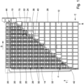
- FIG. 1 a stacking device for generating decks 10 of sheet elements 12 made of paper, cardboard (including corrugated board) or plastic is shown.
- the stacking device comprises a transport device 14 which is an endless track comprising a push or pull means as an endless belt 16 (see Figure 4 ) which is driven by one or more rollers 18 and is partly wound around deflecting rollers.
- a transport device 14 which is an endless track comprising a push or pull means as an endless belt 16 (see Figure 4 ) which is driven by one or more rollers 18 and is partly wound around deflecting rollers.
- a chain or one or more endless cables can be provided instead of an endless belt 16.
- endless belt is used in the following, chains, cables etc. can be used instead of an endless belt 16.
- the endless belt 16 is driven in a transport direction T (see Figures 1 and 4 ).
- the transport blocks 20 may be arranged with their longer side coinciding with the transport direction T.
- the longer side of the transport blocks may be aligned perpendicular to the transport direction T.
- each transport block 20 has a first longitudinal edge 26 upstream (here the left hand edge seen in transport direction T) and an opposite edge 28.
- the edges 26 and 28 of all blocks 20 define the longitudinal edges of the transport device.
- a displacement device 30 is arranged above the upper side of the transport device.
- the "upper side” is defined by all transport blocks 20 protruding upwardly from the endless belt 16, i.e. having their upper side being directed upwardly. As endless belt 16 is been moved together with its transport blocks 20 some transport blocks 20 are facing downwardly and some upwardly.
- Displacement device 30 comprises an endless, loop track 32 which guides and drives displacement elements 34 (see Figures 2 to 4 ).
- one single displacement element 34 is attached to a carrier 36, or directly to an endless push or pull element 110, e.g. a chain, endless belt or cable which is moved along track 32.
- the displacement element 34 is placed preferably in the middle of each sheet element longitudinal side, so that the sheet element is not rotated during its sideward shift movement.
- This embodiment allows the carrier 36 to freely rotate around the vertical axis, resulting in a simpler system.
- two displacement elements 34 are attached to a carrier 36 in order to form a fork-like body.
- Carrier 36 has a pin 38 (see Figure 4 ) which protrudes into track 32 in which an endless push or pull element, e.g. a chain, endless belt or cable is moved.
- Pin 38 is coupled to sliders within guide track 32 which are attached to the push or pull element.
- a motor with a gear or friction roller engaging the push or pull element can be used as a drive for moving the endless push or pull element.
- the orientation of the carrier 36 along the vertical axis must be fixed, thus the guide 40 must be arranged to control the orientation of carrier 36.
- Linear guides that are arranged to control the orientation of the guided element, or that let the orientation of the guided element free are well known in the art.
- Figure 6 shows an example of a guide 40 that controls the orientation of the carrier 36
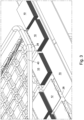
- Figure 7 shows an example of a guide where the orientation of the carrier is not well controlled, but which is simpler to implement.
- Figure 6 shows a guide 40 with two inner grooves 101.
- a guided carrier 102 comprising three wheels with ball bearings and with an outer profile 104 adapted to engage into groove 32.
- the guided carrier 102 When engaged into the groove 101 with its three wheels 106, the guided carrier 102 has a single degree of freedom, resulting in the control of the orientation of the displacement element(s) 34 attached below.
- the guided carrier 102 is connected to and transported by an endless push or pull element 110, e.g. a chain, endless belt or cable, which moves the guided carrier along guide 40.
- the endless push or pull element car be placed in-between the guided carrier 102 and the displacement element(s) 34, as shown in figure 6 , or above the guided carrier 102.
- Figure 7 shows a guide 40 with a groove 112 in which a guided carrier 102 engages.
- the engagement of the guided carrier 102 into the groove 112 fixes the orientation along direction V of the displacement element 34, to ensure a proper alignment of the stacks of sheet elements along stacking direction S.
- the guided carrier 102 is transported by an endless push or pull element 110, e.g. a chain, endless belt or cable, along guide 40.
- Track 32 has a triangular shape with two sides arranged perpendicular to each other. The first side extends parallel to transport direction T and the second side perpendicular thereto. A third side which is termed "guide" 40 extends at an angle across the upper side (see Figure 1 ).
- Guide 40 may extend at an angle ⁇ of 10-80°, more particular 30-70° with respect to the transport direction T, across the upper side of the transport device (see Figure 1 ).
- Guide 40 extends linearly from an rear end 42 at the left hand side longitudinal edge to a front end 44 at the right hand side longitudinal edge.
- carriers 36 are aligned in different angles with respect to the portion of the track 32 at which they are positioned.
- carriers 36 are arranged inclined to longitudinal direction T of guide 40, whereas in the remainder of track 32 carriers 36 are arranged in track direction.
- Deflector elements or drive elements are provided to align carriers 36 correspondingly.
- each column C is preferably associated with at least one displacement element 34 (as described above).
- the displacement elements 34 are travelling along the endless loop track 32 and numerous displacement elements 34 can be distributed along the endless loop track 32.
- the displacement elements 34 are preferably evenly distributed at a constant distance from each other along the endless loop track 32. This ensures that there is a constant supply of displacement elements 34 in order to continuously engage with the sheet sections 50 in the columns C. Hence, this allows some displacement elements 34 to be in operation (i.e. moving in the columns), while others are positioned on a return path of the endless loop track 32.
- PCT/EP2020/085546 A device and method for creating such partial decks is described in the application PCT/EP2020/085546 .
- the device in PCT/EP2020/085546 is an upstream-located stacking device which is designed to gradually overlap, in the transport direction T, individual sheet elements 12 in several transportation paths (i.e. rows R) on top of each other in order to form partial decks.
- the stacking device of the present disclosure can be used further downstream of the device in PCT/EP2020/085546 to superpose the partial decks from each column C, in a direction perpendicular to the transport direction T, such that a complete deck is created.
- the sheet elements 12 of a column C are displaced beginning from the sheet element 12 on the upstream side, i.e. from the longitudinal edge at the left hand side in the figures, continuously towards the opposite longitudinal edge on the downstream side, i.e. a longitudinal edge on the right hand side in the figures.
- Displacement of sheet elements 12 from upstream to downstream is achieved by displacement elements 34 engaging the upstream edge of the upstream side of sheet element 12 as can be seen in Figure 4 .
- Each pair of displacement elements 34 is associated to the column C at which it starts to contact a sheet element 12.
- Figure 1 shows that carriers 36 move together with their columns C of sheet elements 12 in transport direction.
- Carriers 36 are both moving in transport direction T and transversely thereto in stacking direction.
- the velocity of their movement in transport direction T corresponds to the velocity of the transport device.
- sheet elements 12 of one column C are shifted to edge 28 when being moved in transport direction T by corresponding displacement elements 34.
- Partial decks formed on one of the sheet sections 50 are shifted onto the sheet element adjacent thereto so that the height of the deck is permanently increasing until all sheet elements 12 of one column C are stacked together.
- the displacement elements 34 shift the decks 10 onto a dispatching device 70 in the form of an endless belt.
- the upper side of the dispatching device 70 is arranged slightly underneath the lowermost sheet section 50 which defines edge 28.
- each transport block 20 has at least one associated stop protrusion 48 at its front end.
- Figure 2 shows that the stop protrusions 48 are protruding over the upper side of the transport device and that the stop protrusions 48 of one column C are arranged in a linear line.
- Transport blocks 20 are, for example, molded plastic parts.
- Stop protrusions 48 can be integrally formed to transport blocks 20 or be defined by a separate plate-like part attached to the front side of transport block 20 (see Figure 4 ).
- each sheet section 50 is arranged with a height offset ⁇ h in relation to an adjacent sheet section 50 in the stacking direction S.
- every sheet section 50 exhibits a height offset ⁇ h with its adjacent sheet section 50.
- This height offset must be at least as large, but preferably larger than the sheet element thickness, in order to ensure a proper stacking of the sheet elements.
- the sheet section which is the most upstream is also referred to as the "highest” sheet section, or the sheet section at the "upper side", the one which is the most downstream is referred to as the "lowermost” sheet section, even if their respective height compared to the horizontal might be the same.
- This height offset ⁇ h allows the sheet elements are shifted onto each other (as can be seen in Figure 2 ).
- the sheet sections 50 of one column C have a first longitudinal edge 50A and a second longitudinal edge 50B.
- the second longitudinal edge 50B is located further downstream in the stacking direction S than the first longitudinal edge 50A.
- the second longitudinal edge 50B of the first sheet section 50 is located at a higher vertical position than the first longitudinal edge 50A of an adjacent second sheet section 50, arranged further downstream in the stacking direction S. This provides a height offset ⁇ h in the stacking direction S between the adjacent sheet sections 50.
- the first longitudinal edge 50A and the second longitudinal edge 50B can be aligned with the respective edges of the sheet elements 12.
- displacement elements 34 extend into an associated lateral groove 52 in its transport block 20.
- Lateral grooves 52 extend along the full width of its transport block 20 so that displacement elements 34 can enter the lateral grooves at edge 26 and exit therefrom at edge 28.
- Longitudinal grooves 54 in the transport block 20 allow plate-like guides to extend in-between the rows R of sheet elements 12 in order to ensure that the sheet elements 12 are positioned correctly on the sheet sections 50.
Landscapes
- Engineering & Computer Science (AREA)
- Mechanical Engineering (AREA)
- Pile Receivers (AREA)
- Discharge By Other Means (AREA)
Claims (14)
- Stapelvorrichtung zum Erzeugen von Etagen (10) von Blattelementen (12), wobei die Stapelvorrichtung umfasst:eine Transportvorrichtung (14) mit einer Oberseite zum Transportieren der Blattelemente (12), wobei die Oberseite eine Vielzahl von Blattabschnitten (50) aufweist, die dazu konfiguriert sind, darauf Blattelemente (12), die darauf eingerichtet werden sollen, aufzunehmen, wobei die Vielzahl von Blattabschnitten (50) in Reihen (R) und Spalten (C) eingerichtet ist,wobei Reihen (R) in einer Transportrichtung (T) der Stapelvorrichtung und Spalten (C) senkrecht dazu in einer Stapelrichtung (S) ausgerichtet sind,und wobei die Vielzahl von Blattabschnitten (50) einer Spalte (C) mindestens einen ersten Blattabschnitt (50) und mindestens einen angrenzenden, in Stapelrichtung (S) weiter stromabwärts eingerichteten zweiten Blattabschnitt (50) umfasst, und wobei in der Stapelrichtung (S) zwischen dem ersten Blattabschnitt (50) und dem zweiten Blattabschnitt (50) ein Höhenversatz (Δh) bereitgestellt ist, wobei es der Höhenversatz (Δh) erlaubt, mindestens einem Blattelement (12) auf dem ersten Blattabschnitt über ein angrenzendes Blattelement auf dem zweiten Blattabschnitt (50) bewegt und darauf positioniert zu werden,mindestens ein Verschiebeelement (34), das angetrieben wird, um quer zu der Transportrichtung (T) entlang der Blattabschnitte (50) einer Spalte (C) bewegt zu werden,wobei das Verschiebeelement (34) an den Blattabschnitten (50) einer Spalte (C) eingreift, um das mindestens eine Blattelement (12) eines ersten Blattabschnitts (50) auf das Blattelement (12) des angrenzenden zweiten Blattabschnitts (50) zu verschieben, und wobei oberhalb der Blattabschnitte (50) eine Führung (40) für das mindestens eine Verschiebeelement (34) eingerichtet ist, dadurch gekennzeichnet, dass sich die Führung (40) in der Transportrichtung (T) schräg über die Oberseite der Transportvorrichtung (14) derart erstreckt, dass sich in einer Draufsicht auf die Stapelvorrichtung gesehen die Führung (40) schräg zu der Transportrichtung (T) erstreckt.
- Stapelvorrichtung nach Anspruch 1, wobei Anschlagvorsprünge (48) bereitgestellt sind, die die vorderen Enden der Blattabschnitte (50) definieren, wobei bevorzugter die Anschlagvorsprünge (48) einer Spalte (C) in einer linearen Anordnung bereitgestellt sind.
- Stapelvorrichtung nach einem der Ansprüche 1 oder 2, wobei die Blattabschnitte (50) in Stapelrichtung (S) geneigt sind.
- Stapelvorrichtung nach Anspruch 3, wobei die Blattabschnitte (50) in Stapelrichtung (S) nach oben geneigt sind.
- Stapelvorrichtung nach einem der vorstehenden Ansprüche, wobei jeder Spalte (C) mindestens ein Verschiebeelement (34) zugeordnet ist.
- Stapelvorrichtung nach einem der vorstehenden Ansprüche, wobei die Führung (40) Teil einer endlosen Schleifenbahn (32) bildet.
- Stapelvorrichtung nach einem der vorstehenden Ansprüche, wobei sich die Verschiebeelemente (34) bis zu einer Position unterhalb der Blattabschnitte (50) erstrecken.
- Stapelvorrichtung nach Anspruch 7, wobei die Blattabschnitte (50) mindestens eine seitliche Nut (52) umfassen, in die das Verschiebeelement (34) ragt, wobei sich die seitliche Nut (52) insbesondere senkrecht zu der Transportrichtung (T) erstreckt.
- Stapelvorrichtung nach Anspruch 8, wobei für jede Spalte (C) mindestens zwei Verschiebeelemente (34) bereitgestellt sind, wobei den Verschiebeelementen (34) jeweils eine einzige Nut (52) in den Blattabschnitten (50) einer Spalte (C) zugeordnet ist.
- Stapelvorrichtung nach Anspruch 9, wobei die Verschiebeelemente (34) jeder Spalte (C) an einem gemeinsamen, durch die Führung (40) geführten Träger (36) befestigt sind.
- Stapelvorrichtung nach einem der vorstehenden Ansprüche, wobei die Transportgeschwindigkeit des Blattabschnitts (50) in Transportrichtung (T) der Geschwindigkeit des Verschiebeelements (34) in Transportrichtung (T) entspricht.
- Stapelvorrichtung nach einem der vorstehenden Ansprüche, wobei die Transportvorrichtung (14) als eine Endlosbahn gebildet ist, wobei die Endlosbahn insbesondere ein Endlosband umfasst, und/oder wobei Profiltransportblöcke (20), die die Oberseite der Transportvorrichtung (14) definieren, aneinander angebracht sind, insbesondere durch ein endloses Zug- oder Schubelement, oder aneinander angebracht sind, um eine endlose Kette zu bilden.
- Transportblock für die Stapelvorrichtung nach Anspruch 12, wobei der Transportblock (20) eine Profiloberseite und eine entgegengesetzte Unterseite aufweist, wobei die Profiloberseite eine Vielzahl von Blattabschnitten (50) aufweist, die zum Aufnehmen von Blattelementen (12) konfiguriert sind, die darauf eingerichtet werden sollen, und wobei der Höhenversatz (Δh) in der Stapelrichtung (S) zwischen angrenzenden Blattabschnitten (50) bereitgestellt ist.
- Transportblock nach Anspruch 13, wobei der Transportblock (20) ein vorderes und hinteres Ende (22, 24) aufweist, das vordere Ende (22) einen Anschlagvorsprung (48) umfasst, der über die Blattabschnitte (50) hinausragt, und/oder wobei der Transportblock (20) an seiner Oberseite mindestens eine Nut (52) aufweist, die sich parallel zu dem vorderen Ende (22) erstreckt.
Applications Claiming Priority (2)
| Application Number | Priority Date | Filing Date | Title |
|---|---|---|---|
| EP19020685 | 2019-12-10 | ||
| PCT/EP2020/085605 WO2021116325A1 (en) | 2019-12-10 | 2020-12-10 | Stacking device and transport block for a stacking device |
Publications (3)
| Publication Number | Publication Date |
|---|---|
| EP4072985A1 EP4072985A1 (de) | 2022-10-19 |
| EP4072985C0 EP4072985C0 (de) | 2025-04-09 |
| EP4072985B1 true EP4072985B1 (de) | 2025-04-09 |
Family
ID=68847921
Family Applications (1)
| Application Number | Title | Priority Date | Filing Date |
|---|---|---|---|
| EP20820442.0A Active EP4072985B1 (de) | 2019-12-10 | 2020-12-10 | Stapelvorrichtung und transportblock für die stapelvorrichtung |
Country Status (6)
| Country | Link |
|---|---|
| US (1) | US12208983B2 (de) |
| EP (1) | EP4072985B1 (de) |
| JP (1) | JP7304491B2 (de) |
| KR (1) | KR102686538B1 (de) |
| CN (1) | CN114787058B (de) |
| WO (1) | WO2021116325A1 (de) |
Family Cites Families (15)
| Publication number | Priority date | Publication date | Assignee | Title |
|---|---|---|---|---|
| JPS5214912B2 (de) * | 1973-07-27 | 1977-04-25 | ||
| US4280690A (en) * | 1978-07-21 | 1981-07-28 | James Hill | Collator |
| AU530927B2 (en) * | 1978-11-03 | 1983-08-04 | Carta Mundi | Collator |
| DE3217627C2 (de) | 1982-05-11 | 1986-11-27 | Ziegler & Herzinger Maschinenbau GmbH, 8901 Steppach | Vorrichtung zum Zusammenstellen von Zuschnitten zu Stößen |
| JP5321394B2 (ja) | 2009-09-30 | 2013-10-23 | ブラザー工業株式会社 | シート搬送装置及び画像記録装置 |
| CN103402899B (zh) | 2010-12-21 | 2016-11-09 | 西门子公司 | 堆叠设备和堆叠方法 |
| CN102582131A (zh) | 2012-02-08 | 2012-07-18 | 宁波三A集团有限公司 | 扑克牌印后生产工艺及设备 |
| JP5372190B2 (ja) | 2012-03-01 | 2013-12-18 | 京セラドキュメントソリューションズ株式会社 | シート分離搬送機構及びそれを備えたシート搬送装置並びに画像形成装置 |
| RS58560B1 (sr) | 2012-03-23 | 2019-05-31 | C G Bretting Manufacturing Company Inc | Pakerica velike brzine za mala pakovanja |
| JP5949505B2 (ja) | 2012-11-30 | 2016-07-06 | ブラザー工業株式会社 | シート搬送装置 |
| JP6347181B2 (ja) | 2014-08-29 | 2018-06-27 | ブラザー工業株式会社 | シート載置装置および画像形成装置 |
| JP6264619B2 (ja) | 2015-02-09 | 2018-01-24 | 三菱重工機械システム株式会社 | フロントストップ装置,シート積重装置,カウンタエゼクタ及び製函機 |
| US9791814B2 (en) | 2015-04-09 | 2017-10-17 | Canon Kabushiki Kaisha | Image forming apparatus |
| DK201670379A1 (en) | 2016-05-30 | 2017-12-11 | Schur Packaging Systems Ab | Pile Sheet Remover |
| EP4072984B1 (de) | 2019-12-10 | 2025-03-12 | Bobst Mex Sa | Verfahren und stapelvorrichtung zur erzeugung von blattelementesätzen |
-
2020
- 2020-12-10 EP EP20820442.0A patent/EP4072985B1/de active Active
- 2020-12-10 WO PCT/EP2020/085605 patent/WO2021116325A1/en not_active Ceased
- 2020-12-10 JP JP2022533620A patent/JP7304491B2/ja active Active
- 2020-12-10 KR KR1020227022655A patent/KR102686538B1/ko active Active
- 2020-12-10 CN CN202080086059.0A patent/CN114787058B/zh active Active
- 2020-12-10 US US17/756,998 patent/US12208983B2/en active Active
Also Published As
| Publication number | Publication date |
|---|---|
| KR102686538B1 (ko) | 2024-07-22 |
| WO2021116325A1 (en) | 2021-06-17 |
| EP4072985C0 (de) | 2025-04-09 |
| KR20220105672A (ko) | 2022-07-27 |
| JP7304491B2 (ja) | 2023-07-06 |
| US12208983B2 (en) | 2025-01-28 |
| US20230009808A1 (en) | 2023-01-12 |
| CN114787058A (zh) | 2022-07-22 |
| JP2023504847A (ja) | 2023-02-07 |
| CN114787058B (zh) | 2024-06-21 |
| EP4072985A1 (de) | 2022-10-19 |
Similar Documents
| Publication | Publication Date | Title |
|---|---|---|
| US4280690A (en) | Collator | |
| CN102224093B (zh) | 封套输送装置和相关方法 | |
| JPH08324867A (ja) | 高速印刷紙のスタッキング及び位置合わせ装置 | |
| EP0767126B1 (de) | Umlenkvorrichtung zum Transport von Produkten, insbesondere von graphischen Produkten oder Verlagsprodukten | |
| US6837360B2 (en) | Retractable transfer device metering and product arranging apparatus and methods | |
| US5342040A (en) | Turning device for sheets of paper in a feed web | |
| EP4072985B1 (de) | Stapelvorrichtung und transportblock für die stapelvorrichtung | |
| US4331327A (en) | Apparatus for destacking at least two stacks of flexible flat structures, especially sheets or printed products | |
| US20070138728A1 (en) | Sheet post-processing apparatus | |
| AU2004203812B2 (en) | Method and device for the conversion of a conveyed stream of flat articles | |
| EP4072984B1 (de) | Verfahren und stapelvorrichtung zur erzeugung von blattelementesätzen | |
| US6786328B2 (en) | Method and device for transforming a supply stream of flat stream elements, in particular a supply stream in which the elements are conveyed overlapping one another | |
| JP2020050502A (ja) | 媒体搬送装置、媒体処理装置、及び記録システム | |
| US20070138731A1 (en) | Sheet post-processing apparatus | |
| US6695302B1 (en) | Method and apparatus for separating a stream of spaced documents into discrete groups | |
| JP3583139B2 (ja) | 平らな発送物の搬送装置 | |
| US5364090A (en) | Sequence stacker | |
| JPH08169593A (ja) | シート照合装置及びシートの配列の整理方法 | |
| US7744079B2 (en) | Multi-station system and method for processing paper postal items | |
| GB1601166A (en) | Apparatus for conveying stacks of articles | |
| GB1589595A (en) | Sheet distributor | |
| JPH01133866A (ja) | シ−ト受取り装置 | |
| FI85826C (fi) | Anlaeggning foer att valbart leda arkformiga foeremaol till tvao skilda loepbanor. | |
| SE449342B (sv) | Bandtransportor med band bildat av sida vid sida placerade remmar | |
| GB2447341A (en) | Sheet collating conveyor apparatus |
Legal Events
| Date | Code | Title | Description |
|---|---|---|---|
| STAA | Information on the status of an ep patent application or granted ep patent |
Free format text: STATUS: UNKNOWN |
|
| STAA | Information on the status of an ep patent application or granted ep patent |
Free format text: STATUS: THE INTERNATIONAL PUBLICATION HAS BEEN MADE |
|
| PUAI | Public reference made under article 153(3) epc to a published international application that has entered the european phase |
Free format text: ORIGINAL CODE: 0009012 |
|
| STAA | Information on the status of an ep patent application or granted ep patent |
Free format text: STATUS: REQUEST FOR EXAMINATION WAS MADE |
|
| 17P | Request for examination filed |
Effective date: 20220512 |
|
| AK | Designated contracting states |
Kind code of ref document: A1 Designated state(s): AL AT BE BG CH CY CZ DE DK EE ES FI FR GB GR HR HU IE IS IT LI LT LU LV MC MK MT NL NO PL PT RO RS SE SI SK SM TR |
|
| DAV | Request for validation of the european patent (deleted) | ||
| DAX | Request for extension of the european patent (deleted) | ||
| GRAP | Despatch of communication of intention to grant a patent |
Free format text: ORIGINAL CODE: EPIDOSNIGR1 |
|
| STAA | Information on the status of an ep patent application or granted ep patent |
Free format text: STATUS: GRANT OF PATENT IS INTENDED |
|
| INTG | Intention to grant announced |
Effective date: 20250103 |
|
| GRAS | Grant fee paid |
Free format text: ORIGINAL CODE: EPIDOSNIGR3 |
|
| GRAA | (expected) grant |
Free format text: ORIGINAL CODE: 0009210 |
|
| STAA | Information on the status of an ep patent application or granted ep patent |
Free format text: STATUS: THE PATENT HAS BEEN GRANTED |
|
| AK | Designated contracting states |
Kind code of ref document: B1 Designated state(s): AL AT BE BG CH CY CZ DE DK EE ES FI FR GB GR HR HU IE IS IT LI LT LU LV MC MK MT NL NO PL PT RO RS SE SI SK SM TR |
|
| REG | Reference to a national code |
Ref country code: GB Ref legal event code: FG4D |
|
| REG | Reference to a national code |
Ref country code: CH Ref legal event code: EP |
|
| REG | Reference to a national code |
Ref country code: DE Ref legal event code: R096 Ref document number: 602020049221 Country of ref document: DE |
|
| REG | Reference to a national code |
Ref country code: IE Ref legal event code: FG4D |
|
| U01 | Request for unitary effect filed |
Effective date: 20250429 |
|
| U07 | Unitary effect registered |
Designated state(s): AT BE BG DE DK EE FI FR IT LT LU LV MT NL PT RO SE SI Effective date: 20250507 |
|
| PG25 | Lapsed in a contracting state [announced via postgrant information from national office to epo] |
Ref country code: ES Free format text: LAPSE BECAUSE OF FAILURE TO SUBMIT A TRANSLATION OF THE DESCRIPTION OR TO PAY THE FEE WITHIN THE PRESCRIBED TIME-LIMIT Effective date: 20250409 |
|
| PG25 | Lapsed in a contracting state [announced via postgrant information from national office to epo] |
Ref country code: NO Free format text: LAPSE BECAUSE OF FAILURE TO SUBMIT A TRANSLATION OF THE DESCRIPTION OR TO PAY THE FEE WITHIN THE PRESCRIBED TIME-LIMIT Effective date: 20250709 Ref country code: GR Free format text: LAPSE BECAUSE OF FAILURE TO SUBMIT A TRANSLATION OF THE DESCRIPTION OR TO PAY THE FEE WITHIN THE PRESCRIBED TIME-LIMIT Effective date: 20250710 |
|
| PG25 | Lapsed in a contracting state [announced via postgrant information from national office to epo] |
Ref country code: PL Free format text: LAPSE BECAUSE OF FAILURE TO SUBMIT A TRANSLATION OF THE DESCRIPTION OR TO PAY THE FEE WITHIN THE PRESCRIBED TIME-LIMIT Effective date: 20250409 |
|
| PG25 | Lapsed in a contracting state [announced via postgrant information from national office to epo] |
Ref country code: HR Free format text: LAPSE BECAUSE OF FAILURE TO SUBMIT A TRANSLATION OF THE DESCRIPTION OR TO PAY THE FEE WITHIN THE PRESCRIBED TIME-LIMIT Effective date: 20250409 |
|
| PG25 | Lapsed in a contracting state [announced via postgrant information from national office to epo] |
Ref country code: RS Free format text: LAPSE BECAUSE OF FAILURE TO SUBMIT A TRANSLATION OF THE DESCRIPTION OR TO PAY THE FEE WITHIN THE PRESCRIBED TIME-LIMIT Effective date: 20250709 |
|
| PG25 | Lapsed in a contracting state [announced via postgrant information from national office to epo] |
Ref country code: IS Free format text: LAPSE BECAUSE OF FAILURE TO SUBMIT A TRANSLATION OF THE DESCRIPTION OR TO PAY THE FEE WITHIN THE PRESCRIBED TIME-LIMIT Effective date: 20250809 |
|
| REG | Reference to a national code |
Ref country code: CH Ref legal event code: U11 Free format text: ST27 STATUS EVENT CODE: U-0-0-U10-U11 (AS PROVIDED BY THE NATIONAL OFFICE) Effective date: 20260101 |
|
| PGFP | Annual fee paid to national office [announced via postgrant information from national office to epo] |
Ref country code: GB Payment date: 20251219 Year of fee payment: 6 |
|
| PG25 | Lapsed in a contracting state [announced via postgrant information from national office to epo] |
Ref country code: SM Free format text: LAPSE BECAUSE OF FAILURE TO SUBMIT A TRANSLATION OF THE DESCRIPTION OR TO PAY THE FEE WITHIN THE PRESCRIBED TIME-LIMIT Effective date: 20250409 |
|
| PG25 | Lapsed in a contracting state [announced via postgrant information from national office to epo] |
Ref country code: CZ Free format text: LAPSE BECAUSE OF FAILURE TO SUBMIT A TRANSLATION OF THE DESCRIPTION OR TO PAY THE FEE WITHIN THE PRESCRIBED TIME-LIMIT Effective date: 20250409 |
|
| PG25 | Lapsed in a contracting state [announced via postgrant information from national office to epo] |
Ref country code: SK Free format text: LAPSE BECAUSE OF FAILURE TO SUBMIT A TRANSLATION OF THE DESCRIPTION OR TO PAY THE FEE WITHIN THE PRESCRIBED TIME-LIMIT Effective date: 20250409 |
|
| U20 | Renewal fee for the european patent with unitary effect paid |
Year of fee payment: 6 Effective date: 20251230 |
|
| PLBE | No opposition filed within time limit |
Free format text: ORIGINAL CODE: 0009261 |
|
| STAA | Information on the status of an ep patent application or granted ep patent |
Free format text: STATUS: NO OPPOSITION FILED WITHIN TIME LIMIT |