EP4072840B1 - Verfahren zum zuordnen einer identifikationsinformation mit einem reifen während dessen fertigung, und vorrichtung zu diesem verfahren - Google Patents
Verfahren zum zuordnen einer identifikationsinformation mit einem reifen während dessen fertigung, und vorrichtung zu diesem verfahren Download PDFInfo
- Publication number
- EP4072840B1 EP4072840B1 EP20842025.7A EP20842025A EP4072840B1 EP 4072840 B1 EP4072840 B1 EP 4072840B1 EP 20842025 A EP20842025 A EP 20842025A EP 4072840 B1 EP4072840 B1 EP 4072840B1
- Authority
- EP
- European Patent Office
- Prior art keywords
- tyre
- identification code
- reading
- rfid tag
- processed
- Prior art date
- Legal status (The legal status is an assumption and is not a legal conclusion. Google has not performed a legal analysis and makes no representation as to the accuracy of the status listed.)
- Active
Links
Images


Classifications
-
- B—PERFORMING OPERATIONS; TRANSPORTING
- B29—WORKING OF PLASTICS; WORKING OF SUBSTANCES IN A PLASTIC STATE IN GENERAL
- B29D—PRODUCING PARTICULAR ARTICLES FROM PLASTICS OR FROM SUBSTANCES IN A PLASTIC STATE
- B29D30/00—Producing pneumatic or solid tyres or parts thereof
- B29D30/0061—Accessories, details or auxiliary operations not otherwise provided for
- B29D2030/0083—Attaching monitoring devices to tyres before or after vulcanization by inserting them inside tyre cavities
-
- B—PERFORMING OPERATIONS; TRANSPORTING
- B29—WORKING OF PLASTICS; WORKING OF SUBSTANCES IN A PLASTIC STATE IN GENERAL
- B29D—PRODUCING PARTICULAR ARTICLES FROM PLASTICS OR FROM SUBSTANCES IN A PLASTIC STATE
- B29D30/00—Producing pneumatic or solid tyres or parts thereof
- B29D30/06—Pneumatic tyres or parts thereof (e.g. produced by casting, moulding, compression moulding, injection moulding, centrifugal casting)
- B29D30/0601—Vulcanising tyres; Vulcanising presses for tyres
- B29D30/0633—After-treatment specially adapted for vulcanising tyres
Definitions
- the present invention relates to a method for associating identification information with a tyre being processed.
- the present invention also relates to an apparatus for associating identification information with a tyre being processed.
- a tyre for vehicle wheels generally comprises a carcass structure including at least one carcass ply having respectively opposite end flaps in engagement with respective annular anchoring structures, generally referred to as "bead wires", integrated into the regions usually identified as “beads”, the inside diameter of which substantially matches a so-called “fitting diameter” of the tyre for fitting it onto a respective rim.
- the tyre also comprises a crown structure including at least one belt band located in a radially external position relative to the carcass ply, and a tread band which is radially external to the belt band.
- a so-called "underlayer” of elastomeric material may be interposed, the properties of which are suitable for providing a stable union between the belt band(s) and the tread band.
- respective sidewalls of elastomeric material are applied to the side surfaces of the carcass structure, each extending from one of the side edges of the tread band up to the respective annular bead anchoring structure.
- the carcass ply is internally coated with a layer of elastomeric material, preferably a butyl-based one, commonly referred to as "liner", which has optimal air tightness properties and extends from one bead to the other.
- elastomeric material refers to a compound comprising at least one elastomeric polymer and at least one reinforcing filler.
- said compound also comprises additives such as, for example, a cross-linking agent and/or a plasticizer. Thanks to the presence of the cross-linking agent, said material can be cross-linked by heating to form the final product.
- a “component” or “structural component” of a tyre is meant to be any portion of the latter which can perform a specific function, or a part thereof.
- Tyre components include, for example: liner, underliner, sidewall inserts, bead wires, filler inserts, anti-abrasive layer, sidewalls, carcass ply(ies), belt layer(s), tread band, tread band underlayer, underbelt inserts, etc., or a part thereof.
- a "tyre being processed” is a tyre that has not yet completed the building process, i.e. in which the structural components have not all been assembled together yet, and/or which has not yet undergone all the checks and/or operations required prior to the moulding and curing processes.
- building refers to all those operations (including manufacturing, checking and verification operations) undergone by the tyre being processed prior to moulding and curing.
- tyre without any further specification, may refer either to a tyre being processed or to a moulded and cured tyre.
- RFID tag refers to an identification device provided with a memory and a transceiver module.
- the memory stores at least one identification code univocally associated with the RFID tag.
- the transceiver module operates in accordance with the RFID (Radio Frequency IDentification) technology.
- a “passive RFID tag” indicates an RFID tag which, when interrogated by an RFID reading system, will respond by communicating data contained in its own memory.
- a passive RFID tag does not have a battery or an autonomous power supply source. It is powered by the radiation emitted by the RFID reading system.
- a “reading system” refers to a device or a set of devices configured for communicating, via RFID technology, with one or more RFID tags.
- each reading device is configured for emitting, with a certain periodicity, a reading signal.
- an RFID tag When an RFID tag receives such reading signal, it will respond by communicating data contained in its own memory.
- Document EP 2 186 658 A1 describes a tyre and electronic device assembly, and a method for incorporating an electronic device into a tyre.
- the assembly comprises an electronic device including an RFID tag, a dipole antenna, and a compound having permittivity and conductivity compatible with the operation of the dipole antenna.
- the RFID tag and at least a portion of the dipole antenna are embedded within the compound.
- the RFID tag is operationally mounted in the tyre between an apex component positioned above one of the two beads of said tyre and a sidewall, or at a predetermined distance above an ending of a ply layer perpendicular to the parallel cords of said ply layer.
- Document EP 2 524 818 A2 describes a tyre and embedded RFID tag assembly, and a method for manufacturing the same.
- the assembly comprises a carcass; the carcass comprises at least one radially inner ply component extending around a bead core to a ply turn-up portion.
- the ply turn-up portion extends radially outwards from the bead core to a ply turn-up end.
- the carcass further comprises a barrier layer positioned axially inward from and adjacent to the ply component.
- the barrier layer does not extend around the bead core.
- the assembly comprises an RFID tag embedded within the carcass between the barrier layer and the ply component in a lower sidewall region between 10% and 40% of the tyre section height.
- the Applicant observes that the presence and the proper operation of tyre-mounted RFID tags are extremely important, especially for tyre identification, traceability and verification purposes.
- the Applicant observes, in particular, that it is not essentially possible to make up a posteriori, i.e. after the tyre building and curing processes, for the absence or malfunctioning of an RFID tag. In the event that an RFID tag is absent or is not operating correctly, the tyre will have to be discarded.
- the Applicant also observes that the contexts in which RFID tags are associated with tyres and undergo reading/writing operations are typically industrial structures, where there is a significant presence of metallic bodies that contribute to creating an environment that promotes reflections of electromagnetic fields. This is an additional risk factor that may lead to errors when reading/writing RFID tags associated, or to be associated, with tyres.
- the verification of the presence of the RFID tag and of the proper operation thereof, as well as the verification of the association with the respective tyre, should be carried out in such a way as to avoid building and/or curing any tyres lacking a functional, specification-compliant RFID tag.
- the Applicant has thus found that, by making a first check either before or during the building of the tyre being processed, and a second check at the end of the building phase and before the curing phase, it is possible to verify in an exact and accurate manner the presence and the correct operation of the RFID tag associated with a corresponding tyre. Furthermore, by verifying that the RFID tag detected during the first check is exactly the one detected during the second check, it is possible to make sure that such RFID tag is actually the one associated with the tyre, and not, for example, another RFID tag that may be present nearby and detected by mistake.
- the invention relates to a method for associating identification information with a tyre being processed as claimed in claim 1.
- the Applicant believes that it is thus possible to detect the absence or improper operation of the RFID tag in a timely manner, as well as to verify the actual association between the RFID tag and the tyre being processed.
- the invention relates to an apparatus for associating identification information with a tyre being processed as claimed in claim 10.
- the present invention may have at least one of the following preferable features.
- said further code is a barcode.
- said identification information of said tyre being processed comprises said further code.
- said first reading operation is executed by means of a first RFID tag reading device.
- said second reading operation is executed by means of a second RFID tag reading device.
- said first reading device is located at a building station which executes at least one operation of building said tyre being processed.
- said second reading device is located downstream of said building station.
- said reading system comprises a first reading device.
- said first reading device is located at a building station.
- said reading system comprises a second reading device.
- said second reading device is positioned downstream of a building station.
- said first reading operation is executed by said first reading device.
- said second reading operation is executed by said second reading device.
- a detection device is employed.
- said detection device is configured for detecting a further code.
- said further code is associated with said tyre being processed.
- said further code is a barcode.
- said processor is configured for activating said detection device.
- said processor is configured for activating said detection device in order to detect said further code.
- said processor is configured for supplying said further code to said RFID tag writing device.
- said processor is configured for supplying said further code to said RFID tag writing device in order to include said further code in said identification information.
- said processor is configured for generating an alarm signal if said first reading operation does not allow obtaining said first identification code.
- said processor is configured for generating an alarm signal if said second reading operation does not allow obtaining said second identification code.
- said processor is configured for generating an alarm signal if said first identification code turns out to not match said second identification code.
- said processor is configured for activating said reading system in order to execute a third reading operation.
- said processor is configured for activating said reading system in order to execute said third reading operation after the curing of said tyre being processed.
- said processor is configured for obtaining stored data by means of said third reading operation.
- said processor is configured for comparing said stored data with said first identification code.
- said processor is configured for comparing said stored data with said second identification code.
- said processor is configured for comparing said stored data with said identification information.
- a third reading device is employed.
- said third reading operation is executed by said third reading device.
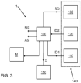
- 1 designates as a whole an apparatus for associating identification information X with a tyre 30 being processed.
- the apparatus 1 ( Fig. 3 ) comprises a reading system 140, configured for reading RFID tags.
- the reading system 140 is associated with a building station 300, which is configured for executing at least one operation of building a tyre 30 being processed. Downstream of the building station 300 there is a curing station 400, prearranged for executing an operation of curing and moulding the tyre 30 being processed.
- the building station 300 is schematized in Figure 1 ; the curing station 400 is schematized in Figure 2 .
- the reading system 140 comprises a first reading device 110.
- the first reading device 110 is located at the building station 300.
- the reading system 140 comprises a second reading device 120.
- the second reading device 120 is positioned downstream of the building station 300, and in particular upstream of the curing station 400.
- the second reading device 120 is preferably interposed between the building station 300 and the curing station 400.
- the apparatus 1 further comprises a processor 100.
- the processor 100 is configured for co-operating with the reading system 140 to read identification codes of RFID tags that are present, for example, at the building station 300.
- an RFID tag 10 is associated with such component 20.
- an RFID tag 10 is directly associated with a tyre 30 being processed when all of its structural components have been assembled or, more generally, at any time during the building thereof.
- the component 20 is a bead wire 20'.
- two bead wires 20', 20" are associated with the tyre 30 being processed, as schematically shown in Figure 1 .
- only one of the two bead wires i.e. the one identified by reference numeral 20'
- the RFID tag 10 is provided with the RFID tag 10. This is necessary for limiting the costs and for ensuring that the tyre 30 being processed and the resulting finished tyre 40 are associated with a single identification code.
- the Applicant observes that it is preferable that only one component per tyre is equipped with a respective RFID tag.
- the RFID tag 10 can be associated with the component 20 by means of a fixing operation, to be executed either manually or in an automated manner.
- the RFID tag 10 is preferably of the passive type.
- the data are preferably structured as shown in the following Table 1: TABLE 1 Binary code MEMORY BANK USE 00 RESERVED
- This memory bank is the password management memory bank, and contains the Access password and the "Kill" password.
- 10 TID TID is a unique part and serial number of the RFID tag, and is permanently locked by the chip manufacturer. This memory bank is not used by tyre manufacturers and is locked by the chip manufacturer.
- 01 UII The unique item identifier is written in this memory bank under the tyre manufacturer's responsibility.
- 11 User Memory The user memory is optional. When available, the parties involved may use it under their own responsibility.
- memory banks There are preferably four memory areas (" memory banks "), respectively marked with the binary address codes "00”, “10”, “01”, "11".
- the first memory area TID is the one that is marked, in the above table, with the binary code "10".
- the datum contained in the first memory area TID is a unique serial number of the RFID tag, and cannot be either modified or overwritten.
- the second memory area UII is the one that is marked, in the above table, with the binary code "01".
- the datum contained in the second memory area UII is written by the tag user - in this case, the tyre manufacturer - and preferably identifies the object whereon the RFID tag is affixed.
- the second memory area UII typically contains a code having no particular meaning, which is set during the production of the RFID tag.
- the datum contained in the first memory area TID ( Tag ID ) is the one which, as will become more apparent below, is preferably read during the checks carried out by means of the present invention.
- the datum contained in the second memory area UII ( Unique Item Identifier ) is preferably the memory area which is written to after said checks. From an operational viewpoint, however, it is envisaged that only the second memory area UII is used, the first memory area TID being read in order to store its content for possible future verifications.
- the processor 100 is configured for activating the reading system 140, and in particular the first reading device 110, in order to execute a first operation of reading the RFID tag 10.
- the first reading operation is executed either before or during the building of the tyre 30 being processed.
- the first reading operation may be executed before the component 20 is associated with the tyre 30 being processed, or it may be executed on the tyre 30 being processed which, at any time during the building process, has been associated with the RFID tag 10, or it may be executed before the RFID tag 10 is associated with the tyre 30 being processed or with a component thereof.
- the first reading operation is executed before the building operations are completed.
- the first reading operation allows obtaining a first identification code ID1 of the RFID tag 10.
- such first identification code ID1 may be the Tag ID contained in the first memory area TID.
- the first identification code ID1 may be the datum contained in the second memory area UII.
- the first identification code ID1 is stored by the processor 100 into a memory M associated therewith.
- the processor 100 is also configured for activating the reading system 140, and in particular the second reading device 120, in order to execute a second reading operation.
- the second reading operation is executed at the end of the building and before the curing of the tyre 30 being processed.
- the second reading operation returns a second identification code ID2.
- the processor 100 then makes a comparison between the first identification code ID1 and the second identification code ID2.
- the processor 100 activates an RFID tag writing device 200.
- a writing operation is thus carried out, and identification information X of the tyre 30 being processed is written to the RFID tag 10.
- the comparison between the first identification code ID1 and the second identification code ID2 makes it possible to verify if the tyre 30 being processed, which comprises or is associated with the component 20 equipped with the RFID tag 10, is really the one from which the tyre 30 exiting the building station 300 has been obtained. More in general, the comparison between the first identification code ID1 and the second identification code ID2 makes it possible to verify if the tyre 30 being processed has that very RFID tag 10 which was read during said first reading operation (and therefore assigned to that specific tyre 30 being processed). In the affirmative case, the process is being carried out correctly, and the identification information X can be written to the RFID tag 10. Otherwise, a problem has occurred and, as will be further explained below, an alarm will be generated.
- the RFID tag writing device 200 is positioned in the vicinity of the second reading device 120.
- the RFID tag writing device 200 may be associated with or integrated into the second reading device 120, forming therewith a single RFID reading/writing apparatus.
- the identification information X preferably comprises data representative of the manufacturer of the tyre 30 being processed and of the finished tyre 40 that will derive therefrom, of the production plant, of the tyre type, and of a progressive number, which allows distinguishing all tyres of the same type being manufactured by the same manufacturer in the same plant.
- the identification information X is written to the second memory area UII of the RFID tag 10.
- the identification information X is structured in accordance with the SGTIN-96 standard, as shown in the following Table 2: TABLE 2 UII EPC GS1 SGTIN-96 Header Filter Value Partition Company Prefix Item Reference Serial Number Length (bits) 8 3 3 da 20 a 40 da 24 a 4 38 Example Value (binary) 00110000 000 010 (for a 34-bit GS1 Company Prefix and a 10-bit Item Reference) 010...01 (34 bits) 010...01 (10 bits) 010...01 (38 bits)
- the identification information X is written on the RFID tag 10 in accordance with the ISO DIS20909, ISO DIS 20910, ISO DIS 20911 and ISO DIS 20912 standards.
- the identification information X is generated by the processor 100 - or by another apparatus associated therewith and belonging, together with the processor 100, to the plant management system.
- the identification information X can be detected directly from the tyre 30 being processed.
- a further code FC e.g. a barcode
- a suitable detection device 150 e.g. a barcode reader
- the processor 100 can read said further code FC and enter the data thereof into the identification information X, so that such data will be written to the RFID tag 10.
- the content of the first memory area TID will also be read and stored - even though it will not be used for the comparison with the second identification code ID2. Reading and storing the content of the first memory area TID may turn out to be useful, for example, for future verifications in order to identify any imitation tyres.
- the processor 100 is configured for acting, by default, upon the second memory area UII - using the content thereof to obtain the first identification code ID1 and the second identification code ID2 and to make the necessary comparisons, while still reading and storing also the content of the first memory area TID.
- the processor 100 is configured for verifying that, among the various distinct RFID tags being read, there are not two of them with a matching, i.e. identical, content of the second memory area UII. If correspondence/identicalness is detected, then the datum cannot be used for discerning one tyre from another, and in such a case the processor 100 is configured for using, for the above-described comparisons, the content of the first memory area TID.
- the processor 100 can generate an alarm signal AS in at least one of the following cases:
- the first case may occur, for example, when the RFID tag 10 has not been associated with the component 20 (e.g. because of an error of the device or of the entrusted operator), or when the RFID tag 10 is faulty/defective and does not work - and hence cannot provide the first identification code ID1.
- the first case may also occur when the reading system 140, and in particular the first reading device 110, receives two distinct identification codes, e.g. because, due to an error, both bead wires to be used in the building process have been provided with an RFID tag.
- the processor 100 will not therefore be able to obtain a single identification code - i.e. the first identification code ID1, and will generate an alarm as a result.
- the second case may occur, for example, when the RFID tag 10 fails during the building process, or when - due to an error in the process management - a tyre has been built which has no RFID tag.
- the third case may occur, for example, when the green tyres downstream of the building station 300 and upstream of the curing station 400 have not been not arranged/handled correctly, and thus the apparatus 1 does not find, downstream of the building station 300, that very same tyre 30 which was previously being built.
- the alarm signal AS may be, for example, an audible and/or visual alarm, so as to draw the attention of an operator, who will then be able to take action.
- the reading system 140 comprises a third reading device 130, located downstream of the curing station 400.
- the processor 100 is configured for activating the reading system 140, and in particular the third reading device 130, in order to execute a third reading operation.
- the third reading operation allows obtaining stored data SD.
- the stored data SD comprise a first portion, consisting of the identification code of the RFID tag on the finished tyre 40, and a second portion consisting of the data written in the memory of the same RFID tag.
- the processor 100 makes a comparison between such stored data SD and at least one of the first identification code ID1, the second identification code ID2 and the identification information X.
- the first portion of the stored data SD is compared with at least one of the first identification code ID1 and the second identification code ID2.
- a comparison is preferably made with either the first identification code ID1 or the second identification code ID2: at this point of the process, it has already been verified that the first identification code ID1 is equal to the second identification code ID2, and a comparison with both of them might prove redundant.
- the second portion of the stored data SD is compared with the identification information X, i.e. the information previously written to the memory of the RFID tag 10.
- the processor 100 will generate an alarm signal AS to report the trouble and preferably call the attention of an operator.
- the processor 100 may generate a simple notification signal representative of the fact that the check has been successful.
- a comparison is only made between the data taken from the re-writable memory of the RFID tag mounted on the finished tyre 40 and the identification information X.
- the processor 100 is configured for generating an alarm in the event that, within a given time of reading the second identification code ID2 or writing the identification information X, the same datum is not read downstream of the curing station 400. In other words, if the readings taken by the third reading device 130 do not provide, within a predefined time, any data corresponding to the second identification code ID2 or to the identification information X, the processor 100 will signal a faulty condition. This is, in fact, a circumstance in which a tyre 30 being processed, after having been built, has not been brought to the curing station 400 and subjected, as expected, to the curing and moulding operations.
- each one of such two or more RFID tags contains, in its second memory area UII, the same identification data of said tyre being processed.
- the checks performed may consider as acceptable the presence of two or more RFID tags on the same tyre being processed, provided that such two or more RFID tags contain the same identification data of the tyre being processed.
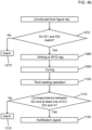
- Figures 4a-4b show a flow chart that illustrates the operations that can be carried out in an embodiment of the method according to the present invention.
- the RFID tag 10 is fixed onto the component 20.
- the component 20 is prepared for the building process, in particular for being associated with the tyre 30 being processed.
- the first reading operation is executed, preferably by means of the first reading device 110.
- the block 1020 indicating the first reading operation, is shown to be separate from and to precede the building operation (block 1040).
- the first reading operation may be executed during the building operation.
- the second reading operation is executed, preferably by means of the second detection device 120, in order to obtain the second identification code ID2.
- a first check is made to see that the second code ID2 is detected. If it is not detected, an alarm signal AS is generated (block 1060'). Otherwise, i.e. if the second identification code ID2 is detected correctly, the procedure can continue with the next block.
- the second identification code ID2 is compared with the first identification code ID1.
- an alarm signal AS is generated (block 1070').
- the RFID tag 10 is written to.
- the identification information X is written, by means of the RFID tag writing device 200, into the memory of the RFID tag 10.
- the third reading operation is executed, preferably by means of the third reading device 130.
- the stored data SD obtained by means of the third reading operation are compared with at least one of the first identification code ID1, the second identification code ID2 and the identification information X.
- the processor 100 may generate a simple notification signal NS to confirm that the process has been carried out correctly (block 1120).
- the blocks 1000 and 1010 may be omitted.
- the first reading operation is executed on an RFID tag 10 that has not yet been affixed to any component 20 prior to the latter being assembled to the tyre 30 being processed.
- processor 100 may be implemented as one or more storage devices, appropriately associated with the processor(s) in use.
Landscapes
- Engineering & Computer Science (AREA)
- Mechanical Engineering (AREA)
- Tires In General (AREA)
- Moulds For Moulding Plastics Or The Like (AREA)
- Heating, Cooling, Or Curing Plastics Or The Like In General (AREA)
- Arrangements For Transmission Of Measured Signals (AREA)
Claims (15)
- Verfahren zum Zuordnen von Identifikationsinformationen zu einem zu bearbeitenden Reifen (30), das Folgendes umfasst:Zuordnen eines RFID-Etiketts (10) zu dem zu bearbeitenden Reifen (30);Ausführen, entweder vor oder während des Aufbaus des zu bearbeitenden Reifens (30), eines ersten Lesevorgangs des RFID-Etiketts (10), um einen ersten Identifikationscode (ID1) von dem RFID-Etikett (10) zu erhalten;am Ende des Aufbaus und vor dem Aushärten des zu bearbeitenden Reifens (30), Ausführen eines zweiten Lesevorgangs, um einen zweiten Identifikationscode (ID2) zu erhalten;ferner gekennzeichnet durch:Aktivieren eines Prozessors (100), um einen Vergleich zwischen dem ersten Identifikationscode (ID1) und dem zweiten Identifikationscode (ID2) durchzuführen;wenn der erste Identifikationscode (ID1) mit dem zweiten Identifikationscode (ID2) übereinstimmt, Aktivieren einer RFID-Etikett-Schreibvorrichtung (200) zum Ausführen eines Schreibvorgangs, um Identifikationsinformationen (X) des Reifens (30), der verarbeitet wird, auf das RFID-Etikett (10) zu schreiben.
- Verfahren nach Anspruch 1, das umfasst:Zuordnen eines weiteren Codes (FC) zu dem zu bearbeitenden Reifen (30);Lesen des weiteren Codes (FC);wobei die Identifikationsinformationen (X) des zu bearbeitenden Reifens (30) den weiteren Code (FC) umfassen.
- Verfahren nach einem der vorhergehenden Ansprüche, das das Erzeugen eines Alarmsignals (AS) in mindestens einem der folgenden Fälle umfasst:der erste Lesevorgang erlaubt es nicht, den ersten Identifikationscode (ID1) zu erhalten;der zweite Lesevorgang erlaubt es nicht, den zweiten Identifikationscode (ID2) zu erhalten;der erste Identifikationscode (ID1) stimmt nicht mit dem zweiten Identifikationscode (ID2) überein.
- Verfahren nach einem der vorhergehenden Ansprüche, wobei der erste Lesevorgang mittels einer ersten RFID-Etikett-Lesevorrichtung (110) und der zweite Lesevorgang mittels einer zweiten RFID-Etikett-Lesevorrichtung (120) ausgeführt wird.
- Verfahren nach einem der vorhergehenden Ansprüche, wobei das RFID-Etikett (10) einer Komponente (20) eines Reifens zugeordnet wird, bevor die Komponente (20) einem Reifen (30) zugeordnet wird, der verarbeitet wird.
- Verfahren nach Anspruch 5, wobei sich die erste Lesevorrichtung (110) an einer Aufbaustation (300) befindet, die mindestens einen Vorgang zum Aufbau des zu bearbeitenden Reifens (30) ausführt.
- Verfahren nach einem der Ansprüche 1 bis 4, wobei das RFID-Etikett (10) dem zu bearbeitenden Reifen (30) zugeordnet ist.
- Verfahren nach einem der Ansprüche 4 bis 7, wobei die zweite Lesevorrichtung (120) stromabwärts der Aufbaustation (300) angeordnet ist.
- Verfahren nach einem der vorhergehenden Ansprüche, das umfasst:Ausführen, nach dem Aushärten des zu bearbeitenden Reifens (30), eines dritten Lesevorgangs, um gespeicherte Daten (SD) zu erhalten;Aktivieren des Prozessors (100), um die gespeicherten Daten (SD) mit mindestens einem des ersten Identifikationscodes (ID1), des zweiten Identifikationscodes (ID2) und der Identifikationsinformationen (X) zu vergleichen;wenn die gespeicherten Daten (SD) mit mindestens einem des ersten Identifikationscodes (ID1), des zweiten Identifikationscodes (ID2) und der Identifikationsinformationen (X) nicht übereinstimmen, Erzeugen eines Alarmsignals (NS).
- Vorrichtung zum Zuordnen von Identifikationsinformationen zu einem zu bearbeitenden Reifen (30), die Folgendes umfasst:ein Lesesystem (140), das zum Lesen von RFID-Etiketts konfiguriert ist;einen Prozessor (100), der für Folgendes konfiguriert ist:- Aktivieren des Lesesystems (140) zum Ausführen, entweder vor oder während des Aufbaus eines zu bearbeitenden Reifens (30), eines ersten Lesevorgangs eines RFID-Etiketts (10), um einen ersten Identifikationscode (ID1) von dem RFID-Etikett (10) zu erhalten;dadurch gekennzeichnet, dass der Prozessor (100) ferner für Folgendes konfiguriert ist:- Aktivieren des Lesesystems (140) zum Ausführen, am Ende des Aufbaus und vor dem Aushärten des zu bearbeitenden Reifens (30), eines zweiten Lesevorgangs, um einen zweiten Identifikationscode (ID2) zu erhalten;- Durchführen eines Vergleichs zwischen dem ersten Identifikationscode (ID1) und dem zweiten Identifikationscode (ID2);- wenn der erste Identifikationscode (ID1) mit dem zweiten Identifikationscode (ID2) übereinstimmt, Aktivieren einer RFID-Etikett-Schreibvorrichtung (200) zum Ausführen eines Schreibvorgangs, um Identifikationsinformationen (X) des Reifens (30), der verarbeitet wird, auf das RFID-Etikett (10) zu schreiben.
- Vorrichtung nach Anspruch 10, wobei das Lesesystem (140) eine erste Lesevorrichtung (110) und eine zweite Lesevorrichtung (120) umfasst;wobei der erste Lesevorgang durch die erste Lesevorrichtung (110) und der zweite Lesevorgang durch die zweite Lesevorrichtung (120) ausgeführt wird;wobei sich die erste Lesevorrichtung (110) an einer Gebäudestation (300) befindet;wobei die zweite Lesevorrichtung (120) stromabwärts von der Gebäudestation (300) angeordnet ist.
- Vorrichtung nach Anspruch 10 oder 11, die eine Erfassungsvorrichtung (150) umfasst, die zum Erfassen eines weiteren Codes (FC) konfiguriert ist, der dem zu bearbeitenden Reifen (30) zugeordnet ist;
wobei der Prozessor (100) für Folgendes konfiguriert ist:- Aktivieren der Erfassungsvorrichtung (150), um den weiteren Code (FC) zu erfassen;- Zuführen des weiteren Codes (FC) zu der RFID-Etikett-Schreibvorrichtung (200), um den weiteren Code (FC) in den Identifikationsinformationen (X) zu enthalten. - Vorrichtung nach Anspruch 10 oder 11, wobei der Prozessor (100) dafür konfiguriert ist, in mindestens einem der folgenden Fälle ein Alarmsignal (AS) zu erzeugen:der erste Lesevorgang erlaubt es nicht, den ersten Identifikationscode (ID1) zu erhalten;der zweite Lesevorgang erlaubt es nicht, den zweiten Identifikationscode (ID2) zu erhalten;der erste Identifikationscode (ID1) stimmt nicht mit dem zweiten Identifikationscode (ID2) überein.
- Vorrichtung nach einem der Ansprüche 10 bis 13, wobei der Prozessor (100) für Folgendes konfiguriert ist:Aktivieren des Lesesystems (140) zum Ausführen, nach dem Aushärten des zu bearbeitenden Reifens (30), eines dritten Lesevorgangs, um gespeicherte Daten (SD) zu erhalten;Vergleichen der gespeicherten Daten (SD) mit mindestens einem des ersten Identifikationscodes (ID1), des zweiten Identifikationscodes (ID2) und der Identifikationsinformationen (X);Erzeugen eines Alarmsignals (AS), wenn die gespeicherten Daten (SD) mit mindestens einem des ersten Identifikationscodes (ID1), des zweiten Identifikationscodes (ID2) und der Identifikationsinformationen (X) nicht übereinstimmen.
- Vorrichtung nach Anspruch 14, wobei das Lesesystem (140) eine dritte Lesevorrichtung (130) umfasst, wobei der dritte Lesevorgang von der dritten Lesevorrichtung (130) ausgeführt wird.
Applications Claiming Priority (2)
| Application Number | Priority Date | Filing Date | Title |
|---|---|---|---|
| IT201900023346 | 2019-12-09 | ||
| PCT/IB2020/061077 WO2021116807A1 (en) | 2019-12-09 | 2020-11-24 | Method for associating identification information with a tyre being processed, and apparatus operating according to said method |
Publications (3)
| Publication Number | Publication Date |
|---|---|
| EP4072840A1 EP4072840A1 (de) | 2022-10-19 |
| EP4072840C0 EP4072840C0 (de) | 2024-03-20 |
| EP4072840B1 true EP4072840B1 (de) | 2024-03-20 |
Family
ID=70154945
Family Applications (1)
| Application Number | Title | Priority Date | Filing Date |
|---|---|---|---|
| EP20842025.7A Active EP4072840B1 (de) | 2019-12-09 | 2020-11-24 | Verfahren zum zuordnen einer identifikationsinformation mit einem reifen während dessen fertigung, und vorrichtung zu diesem verfahren |
Country Status (4)
| Country | Link |
|---|---|
| EP (1) | EP4072840B1 (de) |
| CN (1) | CN114746259B (de) |
| BR (1) | BR112022008272A2 (de) |
| WO (1) | WO2021116807A1 (de) |
Family Cites Families (5)
| Publication number | Priority date | Publication date | Assignee | Title |
|---|---|---|---|---|
| US7467034B2 (en) * | 2002-11-04 | 2008-12-16 | Automotive Technologies International, Inc. | Tire monitoring techniques |
| KR101545385B1 (ko) * | 2013-05-15 | 2015-08-18 | 아시아나아이디티 주식회사 | 알에프아이디 태그를 이용한 타이어 생산 관리 시스템 |
| CN106156964A (zh) * | 2015-04-03 | 2016-11-23 | 软控股份有限公司 | 轮胎的监测方法和装置 |
| US10105997B2 (en) * | 2015-12-21 | 2018-10-23 | The Goodyear Tire & Rubber Company | Integrated TPMS module and RFID tag data sharing system in a tire |
| JP6863002B2 (ja) * | 2017-03-30 | 2021-04-21 | 株式会社デンソーウェーブ | 管理システム |
-
2020
- 2020-11-24 WO PCT/IB2020/061077 patent/WO2021116807A1/en not_active Ceased
- 2020-11-24 CN CN202080081862.5A patent/CN114746259B/zh active Active
- 2020-11-24 BR BR112022008272A patent/BR112022008272A2/pt active Search and Examination
- 2020-11-24 EP EP20842025.7A patent/EP4072840B1/de active Active
Also Published As
| Publication number | Publication date |
|---|---|
| CN114746259B (zh) | 2025-10-28 |
| EP4072840C0 (de) | 2024-03-20 |
| BR112022008272A2 (pt) | 2022-07-26 |
| WO2021116807A1 (en) | 2021-06-17 |
| EP4072840A1 (de) | 2022-10-19 |
| CN114746259A (zh) | 2022-07-12 |
Similar Documents
| Publication | Publication Date | Title |
|---|---|---|
| EP2524818A2 (de) | Eingebettete Transponder und Reifenbaugruppe, und Verfahren zur Konstruktion davon | |
| KR101545385B1 (ko) | 알에프아이디 태그를 이용한 타이어 생산 관리 시스템 | |
| US6192951B1 (en) | Heavy-duty pneumatic radial tire with transponder buried in bead filler | |
| US9002534B2 (en) | System for identifying the components of a vehicle | |
| CN201718165U (zh) | 一种smt信息快速核对系统 | |
| US20240181818A1 (en) | Pneumatic tire equipped with a transponder | |
| US20260109181A1 (en) | Pneumatic tire equipped with a transponder | |
| US11541703B2 (en) | Pneumatic tire equipped with a transponder | |
| EP3653406B1 (de) | Reifen | |
| CN110826670A (zh) | 一种应用于多轮商用车的胎压系统测试方法 | |
| EP4072840B1 (de) | Verfahren zum zuordnen einer identifikationsinformation mit einem reifen während dessen fertigung, und vorrichtung zu diesem verfahren | |
| WO2014061455A1 (ja) | 自動車生産ライン管理システムおよび管理方法 | |
| EP4422854B1 (de) | Verfahren zur herstellung eines reifens mit einer elektronischen vorrichtung | |
| IT201900001575A1 (it) | Pneumatico provvisto di un transponder | |
| JP5311992B2 (ja) | タイヤ生産管理システム | |
| JP5032279B2 (ja) | 更生タイヤの製造方法及び更生タイヤの製造管理システム | |
| CN103592860B (zh) | 一种滤棒输送系统及其方法 | |
| US11458780B2 (en) | Tire component for a green tire | |
| JP2009126111A5 (de) | ||
| KR102945346B1 (ko) | 타이어의 관리를 위한 데이터 구조를 갖는 전자장치를 포함한 타이어 | |
| US20250353266A1 (en) | Tyre provided with a temporary identification label | |
| KR20180068688A (ko) | 알에프아이디 태그 자동부착 장치 및 그 동작 방법 | |
| JP2004167824A (ja) | タイヤへの製造・検査情報の付加方法及び電子チップ組込タイヤ | |
| KR20240139665A (ko) | Rfid가 설치된 차량용 타이어의 제조방법 및 이에 의한 rfid가 설치된 차량용 타이어 | |
| KR20230044700A (ko) | 타이어 |
Legal Events
| Date | Code | Title | Description |
|---|---|---|---|
| STAA | Information on the status of an ep patent application or granted ep patent |
Free format text: STATUS: UNKNOWN |
|
| STAA | Information on the status of an ep patent application or granted ep patent |
Free format text: STATUS: THE INTERNATIONAL PUBLICATION HAS BEEN MADE |
|
| PUAI | Public reference made under article 153(3) epc to a published international application that has entered the european phase |
Free format text: ORIGINAL CODE: 0009012 |
|
| STAA | Information on the status of an ep patent application or granted ep patent |
Free format text: STATUS: REQUEST FOR EXAMINATION WAS MADE |
|
| 17P | Request for examination filed |
Effective date: 20220525 |
|
| AK | Designated contracting states |
Kind code of ref document: A1 Designated state(s): AL AT BE BG CH CY CZ DE DK EE ES FI FR GB GR HR HU IE IS IT LI LT LU LV MC MK MT NL NO PL PT RO RS SE SI SK SM TR |
|
| DAV | Request for validation of the european patent (deleted) | ||
| DAX | Request for extension of the european patent (deleted) | ||
| GRAP | Despatch of communication of intention to grant a patent |
Free format text: ORIGINAL CODE: EPIDOSNIGR1 |
|
| STAA | Information on the status of an ep patent application or granted ep patent |
Free format text: STATUS: GRANT OF PATENT IS INTENDED |
|
| INTG | Intention to grant announced |
Effective date: 20231026 |
|
| GRAS | Grant fee paid |
Free format text: ORIGINAL CODE: EPIDOSNIGR3 |
|
| GRAA | (expected) grant |
Free format text: ORIGINAL CODE: 0009210 |
|
| STAA | Information on the status of an ep patent application or granted ep patent |
Free format text: STATUS: THE PATENT HAS BEEN GRANTED |
|
| AK | Designated contracting states |
Kind code of ref document: B1 Designated state(s): AL AT BE BG CH CY CZ DE DK EE ES FI FR GB GR HR HU IE IS IT LI LT LU LV MC MK MT NL NO PL PT RO RS SE SI SK SM TR |
|
| REG | Reference to a national code |
Ref country code: GB Ref legal event code: FG4D |
|
| REG | Reference to a national code |
Ref country code: CH Ref legal event code: EP |
|
| REG | Reference to a national code |
Ref country code: IE Ref legal event code: FG4D |
|
| REG | Reference to a national code |
Ref country code: DE Ref legal event code: R096 Ref document number: 602020027665 Country of ref document: DE |
|
| U01 | Request for unitary effect filed |
Effective date: 20240404 |
|
| U07 | Unitary effect registered |
Designated state(s): AT BE BG DE DK EE FI FR IT LT LU LV MT NL PT SE SI Effective date: 20240412 |
|
| PG25 | Lapsed in a contracting state [announced via postgrant information from national office to epo] |
Ref country code: GR Free format text: LAPSE BECAUSE OF FAILURE TO SUBMIT A TRANSLATION OF THE DESCRIPTION OR TO PAY THE FEE WITHIN THE PRESCRIBED TIME-LIMIT Effective date: 20240621 |
|
| PG25 | Lapsed in a contracting state [announced via postgrant information from national office to epo] |
Ref country code: RS Free format text: LAPSE BECAUSE OF FAILURE TO SUBMIT A TRANSLATION OF THE DESCRIPTION OR TO PAY THE FEE WITHIN THE PRESCRIBED TIME-LIMIT Effective date: 20240620 Ref country code: HR Free format text: LAPSE BECAUSE OF FAILURE TO SUBMIT A TRANSLATION OF THE DESCRIPTION OR TO PAY THE FEE WITHIN THE PRESCRIBED TIME-LIMIT Effective date: 20240320 |
|
| PG25 | Lapsed in a contracting state [announced via postgrant information from national office to epo] |
Ref country code: RS Free format text: LAPSE BECAUSE OF FAILURE TO SUBMIT A TRANSLATION OF THE DESCRIPTION OR TO PAY THE FEE WITHIN THE PRESCRIBED TIME-LIMIT Effective date: 20240620 Ref country code: NO Free format text: LAPSE BECAUSE OF FAILURE TO SUBMIT A TRANSLATION OF THE DESCRIPTION OR TO PAY THE FEE WITHIN THE PRESCRIBED TIME-LIMIT Effective date: 20240620 Ref country code: HR Free format text: LAPSE BECAUSE OF FAILURE TO SUBMIT A TRANSLATION OF THE DESCRIPTION OR TO PAY THE FEE WITHIN THE PRESCRIBED TIME-LIMIT Effective date: 20240320 Ref country code: GR Free format text: LAPSE BECAUSE OF FAILURE TO SUBMIT A TRANSLATION OF THE DESCRIPTION OR TO PAY THE FEE WITHIN THE PRESCRIBED TIME-LIMIT Effective date: 20240621 |
|
| PG25 | Lapsed in a contracting state [announced via postgrant information from national office to epo] |
Ref country code: IS Free format text: LAPSE BECAUSE OF FAILURE TO SUBMIT A TRANSLATION OF THE DESCRIPTION OR TO PAY THE FEE WITHIN THE PRESCRIBED TIME-LIMIT Effective date: 20240720 |
|
| PG25 | Lapsed in a contracting state [announced via postgrant information from national office to epo] |
Ref country code: SM Free format text: LAPSE BECAUSE OF FAILURE TO SUBMIT A TRANSLATION OF THE DESCRIPTION OR TO PAY THE FEE WITHIN THE PRESCRIBED TIME-LIMIT Effective date: 20240320 |
|
| PG25 | Lapsed in a contracting state [announced via postgrant information from national office to epo] |
Ref country code: ES Free format text: LAPSE BECAUSE OF FAILURE TO SUBMIT A TRANSLATION OF THE DESCRIPTION OR TO PAY THE FEE WITHIN THE PRESCRIBED TIME-LIMIT Effective date: 20240320 |
|
| PG25 | Lapsed in a contracting state [announced via postgrant information from national office to epo] |
Ref country code: CZ Free format text: LAPSE BECAUSE OF FAILURE TO SUBMIT A TRANSLATION OF THE DESCRIPTION OR TO PAY THE FEE WITHIN THE PRESCRIBED TIME-LIMIT Effective date: 20240320 |
|
| PG25 | Lapsed in a contracting state [announced via postgrant information from national office to epo] |
Ref country code: PL Free format text: LAPSE BECAUSE OF FAILURE TO SUBMIT A TRANSLATION OF THE DESCRIPTION OR TO PAY THE FEE WITHIN THE PRESCRIBED TIME-LIMIT Effective date: 20240320 |
|
| PG25 | Lapsed in a contracting state [announced via postgrant information from national office to epo] |
Ref country code: SK Free format text: LAPSE BECAUSE OF FAILURE TO SUBMIT A TRANSLATION OF THE DESCRIPTION OR TO PAY THE FEE WITHIN THE PRESCRIBED TIME-LIMIT Effective date: 20240320 |
|
| PG25 | Lapsed in a contracting state [announced via postgrant information from national office to epo] |
Ref country code: SM Free format text: LAPSE BECAUSE OF FAILURE TO SUBMIT A TRANSLATION OF THE DESCRIPTION OR TO PAY THE FEE WITHIN THE PRESCRIBED TIME-LIMIT Effective date: 20240320 Ref country code: SK Free format text: LAPSE BECAUSE OF FAILURE TO SUBMIT A TRANSLATION OF THE DESCRIPTION OR TO PAY THE FEE WITHIN THE PRESCRIBED TIME-LIMIT Effective date: 20240320 Ref country code: PL Free format text: LAPSE BECAUSE OF FAILURE TO SUBMIT A TRANSLATION OF THE DESCRIPTION OR TO PAY THE FEE WITHIN THE PRESCRIBED TIME-LIMIT Effective date: 20240320 Ref country code: IS Free format text: LAPSE BECAUSE OF FAILURE TO SUBMIT A TRANSLATION OF THE DESCRIPTION OR TO PAY THE FEE WITHIN THE PRESCRIBED TIME-LIMIT Effective date: 20240720 Ref country code: ES Free format text: LAPSE BECAUSE OF FAILURE TO SUBMIT A TRANSLATION OF THE DESCRIPTION OR TO PAY THE FEE WITHIN THE PRESCRIBED TIME-LIMIT Effective date: 20240320 Ref country code: CZ Free format text: LAPSE BECAUSE OF FAILURE TO SUBMIT A TRANSLATION OF THE DESCRIPTION OR TO PAY THE FEE WITHIN THE PRESCRIBED TIME-LIMIT Effective date: 20240320 |
|
| REG | Reference to a national code |
Ref country code: DE Ref legal event code: R097 Ref document number: 602020027665 Country of ref document: DE |
|
| U20 | Renewal fee for the european patent with unitary effect paid |
Year of fee payment: 5 Effective date: 20241127 |
|
| PLBE | No opposition filed within time limit |
Free format text: ORIGINAL CODE: 0009261 |
|
| STAA | Information on the status of an ep patent application or granted ep patent |
Free format text: STATUS: NO OPPOSITION FILED WITHIN TIME LIMIT |
|
| 26N | No opposition filed |
Effective date: 20241223 |
|
| REG | Reference to a national code |
Ref country code: CH Ref legal event code: PL |
|
| PG25 | Lapsed in a contracting state [announced via postgrant information from national office to epo] |
Ref country code: MC Free format text: LAPSE BECAUSE OF FAILURE TO SUBMIT A TRANSLATION OF THE DESCRIPTION OR TO PAY THE FEE WITHIN THE PRESCRIBED TIME-LIMIT Effective date: 20240320 |
|
| REG | Reference to a national code |
Ref country code: CH Ref legal event code: PL |
|
| PG25 | Lapsed in a contracting state [announced via postgrant information from national office to epo] |
Ref country code: CH Free format text: LAPSE BECAUSE OF NON-PAYMENT OF DUE FEES Effective date: 20241130 |
|
| PG25 | Lapsed in a contracting state [announced via postgrant information from national office to epo] |
Ref country code: IE Free format text: LAPSE BECAUSE OF NON-PAYMENT OF DUE FEES Effective date: 20241124 |
|
| U20 | Renewal fee for the european patent with unitary effect paid |
Year of fee payment: 6 Effective date: 20251126 |
|
| PGFP | Annual fee paid to national office [announced via postgrant information from national office to epo] |
Ref country code: GB Payment date: 20251127 Year of fee payment: 6 |
|
| PGFP | Annual fee paid to national office [announced via postgrant information from national office to epo] |
Ref country code: RO Payment date: 20251110 Year of fee payment: 6 |
|
| PG25 | Lapsed in a contracting state [announced via postgrant information from national office to epo] |
Ref country code: HU Free format text: LAPSE BECAUSE OF FAILURE TO SUBMIT A TRANSLATION OF THE DESCRIPTION OR TO PAY THE FEE WITHIN THE PRESCRIBED TIME-LIMIT; INVALID AB INITIO Effective date: 20201124 |
|
| PG25 | Lapsed in a contracting state [announced via postgrant information from national office to epo] |
Ref country code: CY Free format text: LAPSE BECAUSE OF FAILURE TO SUBMIT A TRANSLATION OF THE DESCRIPTION OR TO PAY THE FEE WITHIN THE PRESCRIBED TIME-LIMIT; INVALID AB INITIO Effective date: 20201124 |