EP4071529A1 - Multiports and other devices having connection ports with securing features and methods of making the same - Google Patents
Multiports and other devices having connection ports with securing features and methods of making the same Download PDFInfo
- Publication number
- EP4071529A1 EP4071529A1 EP22169688.3A EP22169688A EP4071529A1 EP 4071529 A1 EP4071529 A1 EP 4071529A1 EP 22169688 A EP22169688 A EP 22169688A EP 4071529 A1 EP4071529 A1 EP 4071529A1
- Authority
- EP
- European Patent Office
- Prior art keywords
- multiport
- connection port
- connector
- securing
- securing feature
- Prior art date
- Legal status (The legal status is an assumption and is not a legal conclusion. Google has not performed a legal analysis and makes no representation as to the accuracy of the status listed.)
- Pending
Links
Images


Classifications
-
- G—PHYSICS
- G02—OPTICS
- G02B—OPTICAL ELEMENTS, SYSTEMS OR APPARATUS
- G02B6/00—Light guides; Structural details of arrangements comprising light guides and other optical elements, e.g. couplings
- G02B6/24—Coupling light guides
- G02B6/36—Mechanical coupling means
- G02B6/38—Mechanical coupling means having fibre to fibre mating means
- G02B6/3807—Dismountable connectors, i.e. comprising plugs
- G02B6/3873—Connectors using guide surfaces for aligning ferrule ends, e.g. tubes, sleeves, V-grooves, rods, pins, balls
- G02B6/3874—Connectors using guide surfaces for aligning ferrule ends, e.g. tubes, sleeves, V-grooves, rods, pins, balls using tubes, sleeves to align ferrules
- G02B6/3878—Connectors using guide surfaces for aligning ferrule ends, e.g. tubes, sleeves, V-grooves, rods, pins, balls using tubes, sleeves to align ferrules comprising a plurality of ferrules, branching and break-out means
- G02B6/3879—Linking of individual connector plugs to an overconnector, e.g. using clamps, clips, common housings comprising several individual connector plugs
-
- G—PHYSICS
- G02—OPTICS
- G02B—OPTICAL ELEMENTS, SYSTEMS OR APPARATUS
- G02B6/00—Light guides; Structural details of arrangements comprising light guides and other optical elements, e.g. couplings
- G02B6/24—Coupling light guides
- G02B6/36—Mechanical coupling means
- G02B6/38—Mechanical coupling means having fibre to fibre mating means
- G02B6/3807—Dismountable connectors, i.e. comprising plugs
- G02B6/381—Dismountable connectors, i.e. comprising plugs of the ferrule type, e.g. fibre ends embedded in ferrules, connecting a pair of fibres
- G02B6/3825—Dismountable connectors, i.e. comprising plugs of the ferrule type, e.g. fibre ends embedded in ferrules, connecting a pair of fibres with an intermediate part, e.g. adapter, receptacle, linking two plugs
-
- G—PHYSICS
- G02—OPTICS
- G02B—OPTICAL ELEMENTS, SYSTEMS OR APPARATUS
- G02B6/00—Light guides; Structural details of arrangements comprising light guides and other optical elements, e.g. couplings
- G02B6/24—Coupling light guides
- G02B6/36—Mechanical coupling means
- G02B6/38—Mechanical coupling means having fibre to fibre mating means
- G02B6/3807—Dismountable connectors, i.e. comprising plugs
- G02B6/381—Dismountable connectors, i.e. comprising plugs of the ferrule type, e.g. fibre ends embedded in ferrules, connecting a pair of fibres
- G02B6/3826—Dismountable connectors, i.e. comprising plugs of the ferrule type, e.g. fibre ends embedded in ferrules, connecting a pair of fibres characterised by form or shape
- G02B6/3831—Dismountable connectors, i.e. comprising plugs of the ferrule type, e.g. fibre ends embedded in ferrules, connecting a pair of fibres characterised by form or shape comprising a keying element on the plug or adapter, e.g. to forbid wrong connection
-
- G—PHYSICS
- G02—OPTICS
- G02B—OPTICAL ELEMENTS, SYSTEMS OR APPARATUS
- G02B6/00—Light guides; Structural details of arrangements comprising light guides and other optical elements, e.g. couplings
- G02B6/24—Coupling light guides
- G02B6/36—Mechanical coupling means
- G02B6/38—Mechanical coupling means having fibre to fibre mating means
- G02B6/3807—Dismountable connectors, i.e. comprising plugs
- G02B6/3833—Details of mounting fibres in ferrules; Assembly methods; Manufacture
- G02B6/3834—Means for centering or aligning the light guide within the ferrule
- G02B6/3835—Means for centering or aligning the light guide within the ferrule using discs, bushings or the like
- G02B6/3837—Means for centering or aligning the light guide within the ferrule using discs, bushings or the like forwarding or threading methods of light guides into apertures of ferrule centering means
-
- G—PHYSICS
- G02—OPTICS
- G02B—OPTICAL ELEMENTS, SYSTEMS OR APPARATUS
- G02B6/00—Light guides; Structural details of arrangements comprising light guides and other optical elements, e.g. couplings
- G02B6/24—Coupling light guides
- G02B6/36—Mechanical coupling means
- G02B6/38—Mechanical coupling means having fibre to fibre mating means
- G02B6/3807—Dismountable connectors, i.e. comprising plugs
- G02B6/3833—Details of mounting fibres in ferrules; Assembly methods; Manufacture
- G02B6/3834—Means for centering or aligning the light guide within the ferrule
- G02B6/3841—Means for centering or aligning the light guide within the ferrule using rods, balls for light guides
-
- G—PHYSICS
- G02—OPTICS
- G02B—OPTICAL ELEMENTS, SYSTEMS OR APPARATUS
- G02B6/00—Light guides; Structural details of arrangements comprising light guides and other optical elements, e.g. couplings
- G02B6/24—Coupling light guides
- G02B6/36—Mechanical coupling means
- G02B6/38—Mechanical coupling means having fibre to fibre mating means
- G02B6/3807—Dismountable connectors, i.e. comprising plugs
- G02B6/3833—Details of mounting fibres in ferrules; Assembly methods; Manufacture
- G02B6/3834—Means for centering or aligning the light guide within the ferrule
- G02B6/3843—Means for centering or aligning the light guide within the ferrule with auxiliary facilities for movably aligning or adjusting the fibre within its ferrule, e.g. measuring position or eccentricity
-
- G—PHYSICS
- G02—OPTICS
- G02B—OPTICAL ELEMENTS, SYSTEMS OR APPARATUS
- G02B6/00—Light guides; Structural details of arrangements comprising light guides and other optical elements, e.g. couplings
- G02B6/24—Coupling light guides
- G02B6/36—Mechanical coupling means
- G02B6/38—Mechanical coupling means having fibre to fibre mating means
- G02B6/3807—Dismountable connectors, i.e. comprising plugs
- G02B6/3833—Details of mounting fibres in ferrules; Assembly methods; Manufacture
- G02B6/3851—Ferrules having keying or coding means
-
- G—PHYSICS
- G02—OPTICS
- G02B—OPTICAL ELEMENTS, SYSTEMS OR APPARATUS
- G02B6/00—Light guides; Structural details of arrangements comprising light guides and other optical elements, e.g. couplings
- G02B6/24—Coupling light guides
- G02B6/36—Mechanical coupling means
- G02B6/38—Mechanical coupling means having fibre to fibre mating means
- G02B6/3807—Dismountable connectors, i.e. comprising plugs
- G02B6/3869—Mounting ferrules to connector body, i.e. plugs
- G02B6/387—Connector plugs comprising two complementary members, e.g. shells, caps, covers, locked together
-
- G—PHYSICS
- G02—OPTICS
- G02B—OPTICAL ELEMENTS, SYSTEMS OR APPARATUS
- G02B6/00—Light guides; Structural details of arrangements comprising light guides and other optical elements, e.g. couplings
- G02B6/24—Coupling light guides
- G02B6/36—Mechanical coupling means
- G02B6/38—Mechanical coupling means having fibre to fibre mating means
- G02B6/3807—Dismountable connectors, i.e. comprising plugs
- G02B6/3873—Connectors using guide surfaces for aligning ferrule ends, e.g. tubes, sleeves, V-grooves, rods, pins, balls
- G02B6/3885—Multicore or multichannel optical connectors, i.e. one single ferrule containing more than one fibre, e.g. ribbon type
-
- G—PHYSICS
- G02—OPTICS
- G02B—OPTICAL ELEMENTS, SYSTEMS OR APPARATUS
- G02B6/00—Light guides; Structural details of arrangements comprising light guides and other optical elements, e.g. couplings
- G02B6/24—Coupling light guides
- G02B6/36—Mechanical coupling means
- G02B6/38—Mechanical coupling means having fibre to fibre mating means
- G02B6/3807—Dismountable connectors, i.e. comprising plugs
- G02B6/389—Dismountable connectors, i.e. comprising plugs characterised by the method of fastening connecting plugs and sockets, e.g. screw- or nut-lock, snap-in, bayonet type
- G02B6/3893—Push-pull type, e.g. snap-in, push-on
-
- G—PHYSICS
- G02—OPTICS
- G02B—OPTICAL ELEMENTS, SYSTEMS OR APPARATUS
- G02B6/00—Light guides; Structural details of arrangements comprising light guides and other optical elements, e.g. couplings
- G02B6/24—Coupling light guides
- G02B6/36—Mechanical coupling means
- G02B6/38—Mechanical coupling means having fibre to fibre mating means
- G02B6/3807—Dismountable connectors, i.e. comprising plugs
- G02B6/3897—Connectors fixed to housings, casing, frames or circuit boards
-
- G—PHYSICS
- G02—OPTICS
- G02B—OPTICAL ELEMENTS, SYSTEMS OR APPARATUS
- G02B6/00—Light guides; Structural details of arrangements comprising light guides and other optical elements, e.g. couplings
- G02B6/24—Coupling light guides
- G02B6/36—Mechanical coupling means
- G02B6/38—Mechanical coupling means having fibre to fibre mating means
- G02B6/3807—Dismountable connectors, i.e. comprising plugs
- G02B6/381—Dismountable connectors, i.e. comprising plugs of the ferrule type, e.g. fibre ends embedded in ferrules, connecting a pair of fibres
- G02B6/3818—Dismountable connectors, i.e. comprising plugs of the ferrule type, e.g. fibre ends embedded in ferrules, connecting a pair of fibres of a low-reflection-loss type
- G02B6/3821—Dismountable connectors, i.e. comprising plugs of the ferrule type, e.g. fibre ends embedded in ferrules, connecting a pair of fibres of a low-reflection-loss type with axial spring biasing or loading means
-
- G—PHYSICS
- G02—OPTICS
- G02B—OPTICAL ELEMENTS, SYSTEMS OR APPARATUS
- G02B6/00—Light guides; Structural details of arrangements comprising light guides and other optical elements, e.g. couplings
- G02B6/24—Coupling light guides
- G02B6/36—Mechanical coupling means
- G02B6/38—Mechanical coupling means having fibre to fibre mating means
- G02B6/3807—Dismountable connectors, i.e. comprising plugs
- G02B6/3833—Details of mounting fibres in ferrules; Assembly methods; Manufacture
- G02B6/3847—Details of mounting fibres in ferrules; Assembly methods; Manufacture with means preventing fibre end damage, e.g. recessed fibre surfaces
- G02B6/3849—Details of mounting fibres in ferrules; Assembly methods; Manufacture with means preventing fibre end damage, e.g. recessed fibre surfaces using mechanical protective elements, e.g. caps, hoods, sealing membranes
-
- G—PHYSICS
- G02—OPTICS
- G02B—OPTICAL ELEMENTS, SYSTEMS OR APPARATUS
- G02B6/00—Light guides; Structural details of arrangements comprising light guides and other optical elements, e.g. couplings
- G02B6/24—Coupling light guides
- G02B6/36—Mechanical coupling means
- G02B6/38—Mechanical coupling means having fibre to fibre mating means
- G02B6/3807—Dismountable connectors, i.e. comprising plugs
- G02B6/3869—Mounting ferrules to connector body, i.e. plugs
- G02B6/3871—Ferrule rotatable with respect to plug body, e.g. for setting rotational position ; Fixation of ferrules after rotation
-
- G—PHYSICS
- G02—OPTICS
- G02B—OPTICAL ELEMENTS, SYSTEMS OR APPARATUS
- G02B6/00—Light guides; Structural details of arrangements comprising light guides and other optical elements, e.g. couplings
- G02B6/24—Coupling light guides
- G02B6/36—Mechanical coupling means
- G02B6/38—Mechanical coupling means having fibre to fibre mating means
- G02B6/3807—Dismountable connectors, i.e. comprising plugs
- G02B6/3887—Anchoring optical cables to connector housings, e.g. strain relief features
- G02B6/3889—Anchoring optical cables to connector housings, e.g. strain relief features using encapsulation for protection, e.g. adhesive, molding or casting resin
-
- G—PHYSICS
- G02—OPTICS
- G02B—OPTICAL ELEMENTS, SYSTEMS OR APPARATUS
- G02B6/00—Light guides; Structural details of arrangements comprising light guides and other optical elements, e.g. couplings
- G02B6/24—Coupling light guides
- G02B6/36—Mechanical coupling means
- G02B6/38—Mechanical coupling means having fibre to fibre mating means
- G02B6/3807—Dismountable connectors, i.e. comprising plugs
- G02B6/389—Dismountable connectors, i.e. comprising plugs characterised by the method of fastening connecting plugs and sockets, e.g. screw- or nut-lock, snap-in, bayonet type
-
- G—PHYSICS
- G02—OPTICS
- G02B—OPTICAL ELEMENTS, SYSTEMS OR APPARATUS
- G02B6/00—Light guides; Structural details of arrangements comprising light guides and other optical elements, e.g. couplings
- G02B6/24—Coupling light guides
- G02B6/36—Mechanical coupling means
- G02B6/38—Mechanical coupling means having fibre to fibre mating means
- G02B6/3807—Dismountable connectors, i.e. comprising plugs
- G02B6/3895—Dismountable connectors, i.e. comprising plugs identification of connection, e.g. right plug to the right socket or full engagement of the mating parts
-
- G—PHYSICS
- G02—OPTICS
- G02B—OPTICAL ELEMENTS, SYSTEMS OR APPARATUS
- G02B6/00—Light guides; Structural details of arrangements comprising light guides and other optical elements, e.g. couplings
- G02B6/24—Coupling light guides
- G02B6/42—Coupling light guides with opto-electronic elements
- G02B6/4201—Packages, e.g. shape, construction, internal or external details
- G02B6/4256—Details of housings
- G02B6/4262—Details of housings characterised by the shape of the housing
-
- G—PHYSICS
- G02—OPTICS
- G02B—OPTICAL ELEMENTS, SYSTEMS OR APPARATUS
- G02B6/00—Light guides; Structural details of arrangements comprising light guides and other optical elements, e.g. couplings
- G02B6/44—Mechanical structures for providing tensile strength and external protection for fibres, e.g. optical transmission cables
- G02B6/4401—Optical cables
-
- G—PHYSICS
- G02—OPTICS
- G02B—OPTICAL ELEMENTS, SYSTEMS OR APPARATUS
- G02B6/00—Light guides; Structural details of arrangements comprising light guides and other optical elements, e.g. couplings
- G02B6/44—Mechanical structures for providing tensile strength and external protection for fibres, e.g. optical transmission cables
- G02B6/4439—Auxiliary devices
- G02B6/444—Systems or boxes with surplus lengths
- G02B6/4441—Boxes
- G02B6/4446—Cable boxes, e.g. splicing boxes with two or more multi fibre cables
-
- G—PHYSICS
- G02—OPTICS
- G02B—OPTICAL ELEMENTS, SYSTEMS OR APPARATUS
- G02B6/00—Light guides; Structural details of arrangements comprising light guides and other optical elements, e.g. couplings
- G02B6/44—Mechanical structures for providing tensile strength and external protection for fibres, e.g. optical transmission cables
- G02B6/4439—Auxiliary devices
- G02B6/4471—Terminating devices ; Cable clamps
- G02B6/4472—Manifolds
-
- G—PHYSICS
- G02—OPTICS
- G02B—OPTICAL ELEMENTS, SYSTEMS OR APPARATUS
- G02B6/00—Light guides; Structural details of arrangements comprising light guides and other optical elements, e.g. couplings
- G02B6/44—Mechanical structures for providing tensile strength and external protection for fibres, e.g. optical transmission cables
- G02B6/4439—Auxiliary devices
- G02B6/4471—Terminating devices ; Cable clamps
- G02B6/4477—Terminating devices ; Cable clamps with means for strain-relieving to interior strengths element
-
- G—PHYSICS
- G02—OPTICS
- G02B—OPTICAL ELEMENTS, SYSTEMS OR APPARATUS
- G02B6/00—Light guides; Structural details of arrangements comprising light guides and other optical elements, e.g. couplings
- G02B6/44—Mechanical structures for providing tensile strength and external protection for fibres, e.g. optical transmission cables
- G02B6/4479—Manufacturing methods of optical cables
Definitions
- the disclosure is directed to devices providing at least one optical connection port along with methods for making the same. More specifically, the disclosure is directed to devices such as multiports comprising a keyed-connection port and a securing feature associated with the connection port for securing an optical connector along with methods of making the same.
- Optical fiber is increasingly being used for a variety of applications, including but not limited to broadband voice, video, and data transmission.
- bandwidth demands increase optical fiber is migrating deeper into communication networks such as in fiber to the premises applications such as FTTx, 5G and the like.
- As optical fiber extended deeper into communication networks the need for making robust optical connections in outdoor applications in a quick and easy manner was apparent.
- hardened fiber optic connectors such as the OptiTap ® plug connector were developed.
- Multiports were also developed for making an optical connection with hardened connectors such as the OptiTap.
- Prior art multiports have a plurality of receptacles mounted through a wall of the housing for protecting an indoor connector inside the housing that makes an optical connection to the external hardened connector of the branch or drop cable.
- FIG. 1 shows a conventional fiber optic multiport 1 having an input fiber optic cable 4 carrying one or more optical fibers to indoor-type connectors inside a housing 3.
- the multiport 1 receives the optical fibers into housing 3 and distributes the optical fibers to receptacles 7 for connection with a hardened connector.
- the receptacles 7 are separate assemblies attached through a wall of housing 3 of the multiport 1.
- the receptacles 7 allow mating with hardened connectors attached to drop or branching cables (not shown) such as drop cables for "fiber-to-the-home” applications.
- optical signals pass through the branch cables, to and from the fiber optic cable 4 by way of the optical connections at the receptacles 7 of multiport 1.
- Fiber optic cable 4 may also be terminated with a fiber optic connector 5.
- Multiports 1 allowed quick and easy deployment for optical networks.
- the housing 3 of the prior art multiport 1 is rugged and weatherable for outdoor deployments, the housings 3 of multiport 1 are relatively bulky for mounting multiple receptacles 7 for the hardened connector on the housing 3.
- Receptacles 7 allow an optical connection between the hardened connector such as the OptiTap male plug connector on the branch cable with a non-hardened connector such as the SC connector disposed within the housing 3, which provides a suitable transition from an outdoor space to an protected space inside the housing 3.
- Receptacle 7 for the OptiTap connector is described in further detail in US Pat. No. 6,579,014 .
- the receptacle includes a receptacle housing and an adapter sleeve disposed therein.
- the receptacles for the hardened connector are large and bulky and require a great deal of surface array when arranged in an array on the housing 3 such as shown with multiport 1.
- conventional hardened connectors use a separate threaded or bayonet coupling that requires rotation about the longitudinal axis of the connector and room for grabbing and rotating the coupling by hand when mounted in an array on the housing 3.
- the housing 3 of the multiport 1 is excessively bulky.
- the multiport 1 may be too boxy and inflexible to effectively operate in smaller storage spaces, such as the underground pits or vaults that may already be crowded.
- having all of the receptacles 7 on the housing 3, as shown in FIG. 1 requires sufficient room for the drop or branch cables attached to the hardened connectors attached to the multiport 1. While pits can be widened and larger storage containers can be used, such solutions tend to be costly and time-consuming.
- Network operators may desire other deployment applications for multiports 1 such as aerial, in a pedestal or mounted on a façade of a building that are not ideal for the prior art multiports 1 for numerous reasons such as congested poles or spaces or for aesthetic concerns.
- FIG. 1 Other multiports designs have been commercialized to address the drawbacks of the prior art multiports depicted in FIG. 1 .
- US 2015/0268434 discloses multiports 1' having one or more connection ports 9 positioned on the end of extensions 8 that project from the housing of the multiport 1' such as depicted in FIG. 2 .
- Connection ports 9 of multiport 1' are configured for mating directly with a hardened connector (not shown) such as an OptiTap without the need to protect the receptacle 7 within a housing like the prior art multiport 1 of FIG. 1 .
- the conventional hardened connectors used with multiport 1' also use a separate threaded or bayonet coupling that requires rotation about the longitudinal axis of the connector along with sufficient space for grabbing and rotating the coupling means by hand. Further, there are aesthetic concerns with the prior art multiports 1' as well.
- the disclosure is directed to devices comprising at least one connection port and a securing feature associated with the connection port.
- Devices that may use the concepts disclosed herein include multiports, closures or wireless devices. Methods of making the devices are also disclosed.
- the devices can have any suitable construction such as disclosed herein such a connection port that is keyed for inhibiting a non-compliant connector from being inserted and potentially causing damage to the device.
- One aspect of the disclosure is directed to devices or multiports comprising a shell, at least one connection port, at least one securing feature passageway, and at least one securing feature.
- the at least one connection port is disposed on the multiport with the at least one connection port comprising an optical connector opening extending from an outer surface of the multiport to a cavity of the multiport and defining a connection port passageway.
- the at least one securing feature is associated with the connection port passageway, where the at least one securing feature is disposed within a portion of the at least one securing feature passageway.
- Another aspect of the disclosure is directed to devices or multiports comprising a shell, at least one connection port, at least one securing feature passageway, at least one securing feature, and at least one securing feature resilient member for biasing a portion of the at least one securing feature.
- the at least one connection port is disposed on the multiport with the at least one connection port comprising an optical connector opening extending from an outer surface of the multiport to a cavity of the multiport and defining a connection port passageway.
- the at least one securing feature is associated with the connection port passageway, where the at least one securing feature is disposed within a portion of the at least one securing feature passageway.
- Still another aspect of the disclosure is directed to devices or multiports comprising a shell, at least one connection port, at least one securing feature passageway, at least one securing feature.
- the at least one connection port is disposed on the multiport with the at least one connection port comprising an optical connector opening extending from an outer surface of the multiport to a cavity of the multiport and defining a connection port passageway.
- the at least one securing feature is associated with the connection port passageway, where the at least one securing feature is disposed within a portion of the at least one securing feature passageway, and the at least one securing feature is capable of translating within a portion of the at least one securing feature passageway.
- Yet another aspect of the disclosure is directed to devices or multiports comprising a shell, at least one connection port, at least one securing feature passageway, at least one securing feature.
- the at least one connection port is disposed on the multiport with the at least one connection port comprising an optical connector opening extending from an outer surface of the multiport to a cavity of the multiport and defining a connection port passageway.
- the at least one securing feature is associated with the connection port passageway, and the at least one securing feature comprises a bore, where the at least one securing feature is disposed within a portion of the at least one securing feature passageway, and the at least one securing feature is capable of translating within a portion of the at least one securing feature passageway.
- a further aspect of the disclosure is directed to devices or multiports comprising a shell, at least one connection port, at least one securing feature passageway, at least one securing feature.
- the at least one connection port is disposed on the multiport with the at least one connection port comprising an optical connector opening extending from an outer surface of the multiport to a cavity of the multiport and defining a connection port passageway.
- the at least one securing feature is associated with the connection port passageway, and the at least one securing feature comprises a bore, where the at least one securing feature is disposed within a portion of the at least one securing feature passageway, and the at least one securing feature is capable of translating within a portion of the at least one securing feature passageway wherein the at least one securing feature translates from a retain position to an open position as a suitable fiber optic connector is inserted into the at least one connection port.
- Still another aspect of the disclosure is directed to devices or multiports comprising a shell, at least one connection port, at least one securing feature passageway, at least one securing feature.
- the at least one connection port is disposed on the multiport with the at least one connection port comprising an optical connector opening extending from an outer surface of the multiport to a cavity of the multiport and defining a connection port passageway.
- the at least one securing feature is associated with the connection port passageway, and the at least one securing feature comprises a bore and a locking feature, where the at least one securing feature is disposed within a portion of the at least one securing feature passageway, and the at least one securing feature is capable of translating within a portion of the at least one securing feature passageway wherein the at least one securing feature translates from a retain position to an open position as a suitable fiber optic connector is inserted into the at least one connection port.
- connection port comprising a shell, at least one connection port, at least one securing feature passageway, at least one securing feature.
- the at least one connection port is disposed on the multiport with the at least one connection port comprising an optical connector opening extending from an outer surface of the multiport to a cavity of the multiport and defining a connection port passageway.
- the at least one securing feature is associated with the connection port passageway, and the at least one securing feature comprises a locking member and an actuator, where the at least one securing feature is disposed within a portion of the at least one securing feature passageway, and the at least one securing feature translates from a retain position to an open position as a suitable fiber optic connector is inserted into the at least one connection port.
- a still further aspect of the disclosure is directed to a wireless device comprising a shell, at least one connection port, at least one securing feature passageway, at least one securing feature.
- the at least one connection port is disposed on the wireless device, the at least one connection port comprising an optical connector opening extending from an outer surface of the wireless device into a cavity of the wireless device and defining a connection port passageway.
- the at least one securing feature is associated with the connection port passageway, and the at least one securing feature comprises a locking member and an actuator, where the at least one securing feature is disposed within a portion of the at least one securing feature passageway.
- the connection port of the wireless device may also comprise other features, structures or components as disclosed herein.
- the concepts for the devices disclosed herein are suitable for providing at least one optical connection to a device for indoor, outdoor or other environments as desired.
- the devices disclosed and explained in the exemplary embodiments are multiports, but the concepts disclosed may be used with any suitable device as appropriate.
- the term "multiport" means any device comprising at least one connection port for making an optical connection and a securing feature associated with the at least one connection port.
- the multiport may be any suitable device having at least one optical connection such as a passive device like an optical closure (hereinafter "closure") or an active device such as a wireless device having electronics for transmitting or receiving a signal.
- the concepts disclosed advantageously allow compact form-factors for devices such as multiports comprising at least one connection port and the securing feature associated with the connection port.
- the concepts are scalable to many connection ports on a device in a variety of arrangements or constructions.
- the securing features disclosed herein for devices engage directly with a portion of connector without conventional structures like prior art devices that require the turning of a coupling nut, bayonet or the like.
- "securing feature” excludes threads and features that cooperate with bayonets on a connector.
- the devices disclosed may allow connection port to be closely spaced and may result in small devices since the room need for turning a threaded coupling nut or bayonet is not necessary.
- the compact form-factors may allow the placement of the devices in tight spaces in indoor, outdoor, buried, aerial, industrial or other applications while providing at least one connection port that is advantageous for a robust and reliable optical connection in a removable and replaceable manner.
- the disclosed devices may also be aesthetically pleasing and provide organization for the optical connections in manner that the prior art multiports cannot provide.
- the devices disclosed are simple and elegant in their designs.
- the devices disclosed comprise at least one connection port and a securing feature associated with the connection port that is suitable for retaining an external fiber optic connector received by the connection port.
- the concepts disclosed advantageously allow the quick and easy connection and retention by inserting the fiber optic connectors directly into the connection port of the device without the need or space considerations for turning a threaded coupling nut or bayonet for retaining the external fiber optic connector.
- the securing features disclosed for use with devices herein may comprise one or more components with at least one component translating for releasing or securing the external fiber optic connector to the device.
- the term "securing feature" excludes threaded portions or features for securing a bayonet disposed on a connector.
- the fiber optic connectors used with the devices disclosed herein may be significantly smaller than conventional connectors used with prior art multiports.
- the present concepts for connection ports on devices allows an increased density of connection ports per volume of the shell since there is no need for accessing and turning the coupling nut or bayonets by hand for securing a fiber optic connector like the prior art multiports.
- the devices disclosed comprise a securing feature for directly engaging with a suitable portion of a connector housing of the external fiber optic connector or the like for securing an optical connection with the device.
- the structure for securing the fiber optic connectors in the devices disclosed allows much smaller footprints for both the devices and the fiber optic connectors along with a quick-connect feature.
- Devices may also have a dense spacing of connection ports if desired.
- the devices disclosed advantageously allow a relatively dense and organized array of connection ports in a relatively small form-factor while still being rugged for demanding environments. As optical networks increase densifications and space is at a premium, the robust and small-form factors for devices such as multiports, closures and wireless devices disclosed herein becomes increasingly desirable for network operators.
- connection port may have a keying portion for inhibiting the insertion of non-compliant connectors that may damage the device.
- FIGS. 3A and 3B respectively depict top and bottom perspective view of explanatory multiports 200 comprising at least one connection port 236 disposed on a connection port insert 230 for making optical connections.
- FIGS. 4A and 4B respectively depict top and bottom perspective views of other explanatory multiports 200 comprising at least one connection port 236 being a portion of a shell of the device.
- at least one connection ports 236 is molded as a portion of shell 210.
- devices such as multiport 200 comprise a shell 210 comprising a body 232 and one or more connection ports 236 disposed on a first end or portion 212 of multiport 200.
- the connection ports 236 are configured for receiving and retaining external fiber optic connectors 10 such as shown in FIG. 3A for making optical connections with the multiport 200.
- Connection ports 236 each comprises a respective optical connector opening 238 extending from an outer surface 234 of the multiport 200 into a cavity 216 of the multiport 200 and defining a connection port passageway 233.
- At least one securing feature 310 is associated with the connection port passageway 233 for cooperating with the external fiber optic connector 10. The securing feature may translate for releasing or securing the external fiber optic connector 10.
- One or more respective securing feature passageways 245 such as shown in FIG. 3C , FIG. 7 or FIG. 32 extend from the outer surface 234 of multiport 200 to a portion of the respective connection port passageways 233 of the multiport 200.
- Respective securing features 310 are associated with the connection port passageways 233 and may be disposed within a portion of the securing feature passageway 245 of the multiport 200.
- connection port passageway 233 is configured for receiving a suitable external fiber optic connector 10 (hereinafter connector) of a fiber optic cable assembly 100 (hereinafter cable assembly).
- connection port passageway 233 is associated with a securing feature 310 for retaining (e.g., securing) connector 10 in the multiport 200.
- the securing feature 310 advantageously allows the user to make a quick and easy optical connection at the connection port 236 of multiport 200.
- the securing feature 310 may operate for providing a connector release feature when actuated.
- the connector 10 may be retained within the respective connection port 236 of the device by pushing and fully-seating the connector 10 within the connection port 236.
- the securing feature 310 is actuated releasing the securing feature from the connector housing and allow the connector to be removed from the connection port 236.
- the at least one securing feature 310 is capable of releasing the connector 10 when translating within a portion of a securing feature passageway 245.
- the full insertion and automatic retention of the connector 10 may advantageously allow one-handed installation of the connector 10 by merely pushing the connector into the connection port 236.
- the devices disclosed accomplish this connector retention feature upon full-insertion by biasing the securing feature to a retain position.
- the securing feature 310 may be designed to require actuation for inserting the connector 10; however, this may require a two-handed operation.
- Securing feature 310 may be designed for holding a minimum pull-out force for connector 10.
- the pull-out force may be selected to release the connector 10 before damage is done to the device or the connector 10.
- the securing feature 310 associated with the connection port 236 may require a pull-out force of about 50 pounds (about 220N) before the connector 10 would release.
- the securing feature 310 may provide a side pull-out force for connector 10 for inhibiting damage as well.
- the securing feature 310 associated with the connection port 236 may provide a side pull-out force of about 25 pounds (about 110N) before the connector 10 would release.
- other pull-out forces such as 75 pounds (about 330N) or 100 (about 440N) pounds are possible along with other side pull-out forces.
- the securing features 310 disclosed herein may take many different constructions or configurations.
- securing features 310 may be formed from a single component as shown in FIG. 3C or a plurality of components as shown in FIG. 30 .
- the securing features 310 or portions of securing features 310 may be constructed as sub-assemblies such as shown in FIG. 50 for easy assembly of multiple securing features 310 or other design considerations.
- Devices such as multiports 200, wireless devices 500 ( FIG. 102 ), or closures 700 ( FIG. 103 ) can have different constructions for securing features, shells, rear connectors, input ports, splitters, keying portions for connection ports, tethers, electronics or components according to the concepts disclosed herein.
- the devices comprise at least one connection port 236 defined by an optical connector opening 238 extending into a cavity of the device 200, 500, 700 along with a securing feature 310 associated with the connection port 236.
- FIGS. 3A and 3B depict a device where the one or more connection ports 236 and the one or more securing feature passageways 245 are a portion of a connector port insert 230.
- Connector port insert 230 is at least partially inserted into shell 210 as represented by the dashed line.
- the dashed line represents a parting line PL between the connector port insert 230 and the shell 210.
- Shell 210 may take many different forms as disclosed herein as well.
- Other devices may have the one or more connection ports 236 and the one or more securing feature passageways 245 formed as a portion of the shell 210, instead of being at least partially inserted into shell as an assembly.
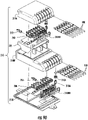
- FIG. 3C is a partially exploded view of another device 200 similar to the multiport 200 of FIGS. 3A and 3B .
- FIG. 3C depicts the multiport 200 comprising at least one connection port 236 disposed on the multiport 200 with the connection port 236 defined by an optical connector opening 238 extending from an outer surface 234 of the multiport 200 into a cavity 216 of the multiport 200 and defining a connection port passageway 233.
- Multiport 200 also comprises at least one securing feature 310 associated with the connection port passageway 233.
- Connection port insert 230 also comprises at least one securing feature passageway 245 for receiving the securing feature 310. As depicted in FIG.
- the securing feature passageways 245 extend from the outer surface 234 of multiport 200 to the respective connection port passageways 233 of the multiport 200.
- Multiport 200 of FIG. 3C comprises a shell 210 with a portion of the connection port insert 230 sized for fitting into a first opening of the shell 210 that leads to a cavity 216.
- Multiport 200 of FIG. 3C also comprises a plurality of adapters 230A for receiving respective rear connectors 252 in alignment with the respective connection port 236.
- a plurality of securing feature locking members 310LM are used retaining the securing features 310 in the securing feature passageway 245 as best shown in FIG. 3F .
- the multiport 200 may also comprise a fiber tray (not numbered) for routing and organizing the optical fibers.
- the fiber tray inhibits damage to optical fibers and also provides a location for the mounting of other components such as splitters, electronics or the like.
- the fiber tray shown in FIG. 3C attaches to one or more slots formed in a retainer 240, which is used for securing adapters to the connection port insert 230.
- FIG. 3D shows an assembly comprising the connection port insert 230 with securing features 310 installed and the rear connectors 252 attached and FIG. 3E shows a cross-section through the connection port passageway 233.
- the optical fibers 250 have been removed from rear connectors 252 of FIGS. 3C and 3D for clarity.
- the assembly has the securing features 310 associated with each connection port passageway 233 disposed within a portion of the securing feature passageway 245.
- the securing feature 310 is a push-button actuator formed as a single component.
- securing feature 310 is biased to a retain position. Specifically, the securing feature 310 is biased in an upward direction using a securing feature resilient member 310R, which is disposed within the connection port insert 230 below the securing feature 310. Consequently, securing feature 310 is capable of translating within a portion of the securing feature passageway 245. As depicted, a sealing feature 310S is disposed on the securing feature 310. Sealing feature 310S provides a seal between the securing feature 310 and the securing feature passageway 245 to inhibit dirt, dust and debris from entering the device.
- Multiport 200 of FIG. 3C also comprises at least one adapter 230A aligned with the respective connection port 236.
- Adapter 230A is suitable for securing a rear connector 252 thereto for aligning the rear connector 252 with the connection port 236.
- One or more optical fibers 252 may be routed from the connection port 236 toward an input connection port 260 of the multiport 200.
- the rear connector 252 may terminate the optical fiber 250 for optical connection at connection port 236 and route the optical fiber 250 to the input connection port 260.
- adapters 230A are secured to connection port insert 230 using retainer 240.
- Adapters 230A may be biased using a resilient member 230RM as shown.
- Rear connectors 252 may take any suitable form and be aligned and secured with the connection ports 236 in any suitable manner.
- input connection port is the location where external optical fibers are received or enter the device, and the input connection port does not require the ability to make an optical connection.
- the securing feature 310 comprises a bore 310B that is aligned with the least one connection port passageway 233 when assembled as shown in FIG. 3E .
- Bore 310B is sized for receiving a suitable connector 10 therethrough for securing the same for optical connectivity.
- Bores or openings through the securing feature 310 may have any suitable shape or geometry for cooperating with its respective connector.
- the bore may have any suitable shape desired including features on the surface of the bore for engaging with a connector.
- the securing feature 310 is capable of moving to an open position when inserting a suitable connector 10 into the connection port passageway 233.
- the securing feature 310 is capable of moving to the retain position automatically. Consequently, the connector 10 is secured within the connection port 236 by securing feature 310 without turning a coupling nut or a bayonet like the prior art multiports. Stated another way, the securing feature 310 translates from the retain position to an open position as a suitable connector 10 is inserted into the connection port 236.
- the securing feature passageway 245 is arranged transversely to a longitudinal axis LA of the multiport 200, but other arrangements are possible. Other securing features may operate in a similar manner, but use an opening instead of a bore that receives the connector therethrough.
- securing feature 310 comprises a locking feature 310L.
- Locking feature 310L cooperates with a portion of the connector 10 when it is fully-inserted into the connection port 236 for securing the same.
- the connector housing 20 of connector 10 may have a cooperating geometry that engages the locking feature 310L of securing feature 310.
- locking feature 310L comprises a ramp (not numbered). The ramp is integrally formed at a portion of the bore 310B with the ramp angling up when looking into the connection port 236. The ramp allows the connector 10 to push and translate the securing feature 310 downward against the securing feature resilient member 310R as the connector 10 is inserted in the connection port 236 as shown.
- Ramp may have any suitable geometry. Once the locking feature 310L of the securing feature 310 is aligned with the cooperating geometry of the locking feature 20L of connector 10, then the securing feature 310 translates so that the locking feature 310L engages the locking feature 20L of connector 10.
- Locking feature 310L comprises a retention surface 310RS.
- the back-side of the ramp of locking feature 310L forms a ledge that cooperates with complimentary geometry on the connector housing 20 of connector 10.
- retention surface 310RS may have different surfaces or edges that cooperate for securing connector 10 for creating the desired mechanical retention.
- the retention surface 310RS may be canted or have a vertical wall for tailoring the pull-out force for the connection port 236.
- the connection port 236 has a sealing location at a connection port passageway sealing surface 233SS with the connector 10 that is located closer to the optical connector opening 238 at the outer surface 234 than the securing feature 310 or locking feature 310L.
- connection port 236 has connection port passageway sealing surface 233CS for the connector 10 disposed at a distance D3 from the optical connector opening 238 and the locking feature 310L and securing feature 310 are disposed at a distance further into the connection port passageway 233 than distance D3.
- securing members 310 may operate in a similar manner for securing connector 10, but comprise more than one component such as an actuator 310A that cooperates with a securing member 310M such as disclosed herein. Additionally, the use of more than one component allows other arrangements for the securing feature passageway 245 relative to a longitudinal axis LA of the device.
- connection port insert 230 comprises a body having a front face FF and a plurality of connection ports 236.
- Each connection port 236 has an optical connector opening 238 extending from the front face FF into the connection port insert 230 with a connection port passageway 233 extending through part of the connection port insert 230 to a rear face RF (not visible) of the connection port insert 230.
- Connection port insert 230 is sized so that at least a portion of the connection port insert 230 fits into a first opening of the shell 210 such as as shown in FIG. 28E .
- the sealing location of the connector port insert 230 with the shell (210) comprises a sealing surface (233SS) disposed a first distance (D1) inward from the outer surface (234) of the device and disposed on a portion of connection port passageway 233.
- the adapters 230A align the rear connectors 252 at a connector mating position MP disposed inward from the outer surface (234) of the multiport at a distance D2, where the second distance (D2) is greater that the first distance (D1).
- the connection port insert 230 may comprise one or more components or include a feature for sealing with the shell 210 for making the multiport weatherproof.
- the devices could be made to be re-enterable if desired.
- connection port inserts 230 may also comprise a sealing location 230SL for providing a surface and location for making a weatherproof attachment to shell 210.
- Sealing location may be disposed at a first distance D1 from the front face 234 of the connector port insert 230. Sealing location is a disposed at a suitable distance D1 for providing a suitable seal with the shell 210.
- Connection port inserts 230 also have a connector mating plane 230MP disposed at a second distance D2 from the front face 234. The connector mating plane 230MP is disposed within the cavity of the shell 210 of the multiport for protecting the connector mating interface.
- the connector port insert 230 comprises a sealing location 230SL disposed at a first distance D1 from the front face 234 and the connector mating position 230MP is disposed at the second distance D2 from the front face 234 with the second distance D2 being greater than the first distance D1.
- the sealing location 230SL may comprise a sealing element 290 disposed between the connection port insert 230 and the shell 210.
- the sealing locations 230SL may comprise respective grooves in the connector port insert 230 or end cap 280 if used. Grooves may extend about the perimeter of the connection port insert 230 and are located at respective distances D1 from the front face 234 of the connection port insert 230 and end cap 280. Grooves may receive one or more appropriately sized O-rings or gaskets 290A for weatherproofing multiport 200.
- the O-rings are suitably sized for creating a seal between the connector port insert 230 and the shell 210.
- suitable O-rings may be a compression O-ring for maintaining a weatherproof seal.
- Other embodiments may use an adhesive or suitable welding of the materials for sealing the device.
- the multiports depicted in FIGS. 3A-3C can have other features or constructions using a second insert 230' that is similar to the connection port insert 230.
- the second insert 230' comprises a body 232 having a front face 234 comprising a plurality of connection ports 236 having an optical connector port opening 238 like the connection port insert 230.
- Second inserts 230' can have other configurations as well for use with the multiports disclosed herein.
- FIGS. 4A and 4B depict multiport 200 comprising a shell 210 comprising a body 232 with one or more connection ports 236 disposed on a first end or portion 212 with each connection port 236 comprising a respective optical connector opening 238.
- the optical connector openings extend from an outer surface 234 of shell 210 of the multiport 200 into a cavity 216 and define a connection port passageway 233.
- One or more respective securing feature passsageways 245 extend from the outer surface 234 of the shell 210 to a portion of the respective connection port passageways 233.
- a plurality of security features 310 are associated with the respective plurality of connection port passageways 233 and at least a portion of the securing features are disposed within a portion of respective securing feature passageways 245.
- the multiports 200 disclosed may have any suitable number of connection ports 236, input connection ports 260 or the like using the concepts disclosed.
- FIGS. 4A and 4B For the sake of brevity, the concepts will be illustrated and described in more detail with respect to the embodiment of FIGS. 4A and 4B , but it is understood that the structure or features disposed in the shell 210 may also be disposed in the connection port insert 230 depicted in FIGS. 3A and 3B as appropriate. Further, multiports according the concepts disclosed may have any suitable number of ports as desired along with suitable optical fiber distribution, pass-throughs, or like.
- FIGS. 5-7 depict various views of multiport 200 of FIGS. 4A and 4B for explaining the concepts and the features may be used with other multiport designs as appropriate or modified with other concepts as appropriate or discussed herein.
- FIGS. 8 and 9 are longitudinal cross-sectional views respectively depicting the optical connection port 236 of the multiport 200 of FIGS. 4A and 4B with and without a connector 10 retained therein.
- FIGS. 10 and 11 are transverse cross-sectional views of the multiport 200 of FIGS. 4A and 4B taken through the securing features 310.
- FIG. 5 depicts a bottom perspective view of a representative multiport 200 of FIGS. 4A and 4B .
- shell 210 is formed by a first portion 210A and a second portion 210B.
- FIG. 5 shows the second portion 210B of shell 210 removed from the first portion 210A for showing the internal construction of multiport 200.
- Multiport 200 is depicted with only one rear (internal) connector 252 shown and the optical fibers 250 removed for clarity purposes in FIG. 5 .
- Optical fibers 250 are routed from one or more of the plurality of connection ports 236 toward an input connection port 260 for optical communication within the multiport 200. Consequently, the input connection port 260 receives one or more optical fibers and then routes the optical signals as desired such as passing the signal through 1:1 distribution, routing through an optical splitter or passing optical fibers through the multiport.
- Optical splitters 275 (hereinafter “splitter(s)") such as shown in FIG. 6 allow a single optical signal to be split into multiple signals such as 1 ⁇ N split, but other splitter arrangements are possible such as a 2xN split.
- a single optical fiber may feed input connection port 260 and use a 1x8 splitter within the multiport 200 to allow eight connector ports 236 for outputs on the multiport 200.
- the input connection port 260 may be configured in an suitable manner with any of the multiports 200 disclosed herein as appropriate such as a single-fiber or multi-fiber port.
- the connection ports 236 may be configured as a single-fiber port or multi-fiber port.
- all of the optical fiber pathways may not be illustrated or portions of the optical fiber pathways may be removed in places so that other details of the design are visible.
- FIG. 6 shows multiport 200 of FIG. 5 with the rear connectors 252 and optical fibers 250 routing through splitter 275 and FIG. 7 is a partially exploded view of FIG. 5 .
- Multiport 200 has one or more optical fibers 250 routed from the one or more connection ports 236 toward an input connection port 260 in a suitable fashion inside cavity 216.
- one or more optical fibers 250 are aligned with the respective connection ports 236 for making an optical connection with connector 10.
- connector 10 comprises a connector housing 20 that has an O-ring 65 that cooperates with sealing location of the connector port 236 at a distance D3, which is located closer to the optical connector opening 238 than securing feature 310.
- FIG. 5 Although only one rear connector 252 is shown in FIG. 5 , a plurality of rear connectors 252 (see FIG. 6 ) are aligned with the respective connector port passageways 233 from the rear portion 237 of connection port passageway 233 within the cavity 216 of the multiport 200.
- the rear connectors 252 are associated with one or more of the plurality of optical fibers 250.
- Each of the respective rear connectors 252 aligns and attaches to a structure such as the adapter 230A or other structure at the rear portion 237 of the connection port passageway 233 in a suitable matter.
- the plurality of rear connectors 252 may comprise a suitable rear connector ferrule 252F as desired and rear connectors 252 may take any suitable form from a simple ferrule that attaches to a standard connector type inserted into an adapter.
- rear connectors 252 may comprise a resilient member for biasing the rear connector ferrule 252F or not. Additionally, rear connectors 252 may further comprise a keying feature.
- a single input optical fiber of the input connection port 260 is routed to a 1:4 splitter 275 and then each one of the individual optical fibers 250 from the splitter is routed to each of the respective four connection ports 236 for optical connection and communication within the multiport.
- Input connection port 260 may be configured in any suitable configuration for the multiports disclosed as desired for the given application. Examples of input connection ports 260 include being configured as a single-fiber input connection, a multi-fiber input connector, a tether input that may be a stubbed cable or terminated with a connector or even one of the connection ports 236 may function as an pass-through connection port as desired.
- two or more optical fibers 250 may be routed from one or more of the plurality of connection ports 236 of the multiport 200 of FIG. 5 .
- two optical fibers may be routed from each of the four connection ports 236 of multiport 200 toward the input connection port 260 with or without a splitter such as single-fiber input connection port 260 using a 1:8 splitter or by using an eight-fiber connection at the input connection port 260 for a 1:1 fiber distribution.
- a marking indicia may be used such as text or color-coding of multiport or marking the input tether (e.g. an orange or green polymer) or the like.
- multiports 200 may be configured for receiving an input tether 270 attached to the multiport such as represented in FIG. 7 .
- FIG. 7A depicts an example of input tether 270 removed from a device.
- Input tether 270 has optical fibers 250 that enter the multiport 200 and are terminated with to rear connectors 252 for making an optical connection at the connection port 236.
- FIG. 7B is a perspective view of a representative multiport 200 having the input tether 270 secured at the input connection port 260.
- other embodiments may retain the securing feature and secure the input tether 270 from inside the device.
- input tether 270 may terminate the other end with a fiber optic connector 278 as depicted or be a stubbed cable as desired.
- connector 278 may be an OptiTip ® connector for optical connection to previously installed distribution cables; however, other suitable single-fiber or multi-fiber connectors may be used for terminating the input tether 270 as desired.
- Input tether 270 may be secured to the multiport 200 in any suitable manner such as adhesive, a collar or crimp, heat shrink or combinations of the same.
- the input tether 270 may also have stubbed optical fibers for splicing in the field if desired, instead of the connector 278.
- the input tether 270 may further comprise a furcation body that has a portion that fits into the multiport 200 at the input port of the shell 210 or the connection port insert 230 such as into the optical connector opening 238 or bore 260B of the input connection port 260, but the furcation body may be disposed within the shell 210 if desired.
- the furcation body is a portion of the input tether that transitions the optical fibers 250 to individual fibers for routing within the cavity 216 of the shell 210 to the respective connector ports.
- a ribbon may be used for insertion into the back end of the ferrule of fiber optic connector 278 and then be routed through the input tether 270 to the furcation body where the optical fibers are then separated out into individual optical fibers 250. From the furcation body the optical fibers 250 may be protected with a buffer layer or not inside the cavity 216 of the multiport 200 and then terminated on rear connector 252 as desired.
- the input tether 270 may be assembled with the rear connectors 252 and/or fiber optic connector 278 in a separate operation from the assembly of multiport 200 if the rear connectors 252 fit through the input port. Thereafter, the rear connectors 252 may be individually threaded through a bore 260B of the input connection port 260 of the multiport or connection port insert 230 with the appropriate routing of the optical fiber slack and then have the rear connectors 252 attached to the appropriate structure for optical communication with the connection port passageways 233 of the multiport 200.
- the furcation body may also be secured to the connection port insert in the manner desired.
- the input tether may be secured to shell 210 or connection port insert 230 using a collar that fits into a cradle. This attachment of the input tether using collar and cradle provides improved pull-out strength and aids in manufacturing; however, other constructions are possible for securing the input tether.
- connection port passageways 233 may be configured for the specific connector 10 intended to be received in the connection port 236. Moreover, the connection port passageways 233 may be configured to provide a weatherproof seal with connector 10 or dust cap 295 for inhibiting dust, dirt, debris or moisture from entering the multiport 200 at a connection port passageway sealing surface 233SS (see FIG. 9 ). Likewise, the connection port passageways 233 should be configured for receiving the specific rear connector 252 from the rear portion 237 for mating and making an optical connection with the connector 10.
- the shell 210 or connection port insert 230 may be configured as a monolithic (e.g., integral) component for making the optical connection between the rear connectors 252 and the external connectors 10 of cable assembly 100; however, other embodiments are possible according to the concepts disclosed that use multiple components.
- the multiports 200 may comprise a plurality of adapters 230A that are integrally-formed with the shell 210 or connection port insert 230.
- the shell 210 or connection port insert 230 may be configured to secure one or more adapters 230A thereto as separate components or assemblies.
- the adapters 230A are aligned with the plurality of connection ports 236. Consequently, optical fibers of the connectors 10 are suitably aligned with the optical fibers 250 disposed within the multiport for optical communication therebetween.
- the adapters 230A may "float" relative to the shell 210 or connection port insert 230. "Float” means that the adapter 230A can have slight movement in the X-Y plane for alignment, and may be inhibited from over-traveling in the Z-direction along the axis of connector insertion so that suitable alignment may be made between mating connectors, which may include a biasing spring for allowing some displacement of the adapter 230A with a suitable restoring force provided by the spring.
- multiports 200 that mate a rear connector 252 such as a SC with connector 10 that has a SC ferrule that is biased forward should have a spring force in connector 10 that mitigates concerns when mated within a ferrule sleeve or use a connector that has a fixed ferrule for mitigating concerns.
- the spring force for connector 10 should be selected to be in a range to overcome sleeve friction and the spring force of the rear connector 10.
- the ferrule 252F of the rear connector 252 contacts the ferrule sleeve 230FS and may displace the ferrule sleeve 230FS to extreme position on the right before the ferrule sleeve 230FS hits a physical stop in the adapter and the ferrule 252F is inserted into the ferrule sleeve 230FS.
- the connector 10 is later inserted into the connector port 236 of the multiport it would be helpful for the ferrule to push the ferrule sleeve 230FS from an extreme position in the adapter if it was displaced.
- the spring selected for biasing the ferrule of connector 10 may be selected to overcome the sum of initial friction along with the insertion friction to move the ferrule sleeve 230FS, thereby inhibiting the ferrule sleeve 230FS from being displaced to a maximum position due to the rear connector 252 being inserted first.
- FIG. 8 depicts a longitudinal sectional view show securing feature 310 disposed within a portion of securing feature passageway 245 along with the rear connector 252 attached at the rear portion 237 of the connection port 236 of multiport 200 and
- FIG. 9 depicts connector 10 of cable assembly 100 inserted into connection port 236 and retained by securing feature 310.
- the rear connector 252 shown in FIGS. 8 and 9 has a SC footprint, but other connectors are possible. If SC connectors are used as the rear connector 252 they have a keying feature 252K that cooperates with the keying feature of adapter 230A.
- adapters 230A comprise a retention feature (not numbered) for seating the adapters 230A in the device adjacent to the connection port passageway 233. In this embodiment, the retention feature is configured to cooperate with a plurality of saddles 210D for receiving and seating adapters 230A.
- Adapters 230A may be secured to the shell 210A or connection port insert 230 using an adapter retainer 240.
- Adapters 230A may comprise latch arms for securing respective rear connectors therein. In other embodiments, adapters 230A may be ganged together or formed from several components, but some adapters or portions thereof could be integrally formed with the multiport as well.
- connector mating plane 230MP between the ferrule of the rear connector 252 and ferrule of connector 10 is disposed within the cavity 216 multiport 200 for protecting the connector mating interface.
- Connector 10 comprises at least one O-ring 65 for sealing with the connector port passageway 233 at a sealing surface 233SS when the connector 10 is fully inserted into the connection port 236.
- connector 10 includes a locking feature 20L on the housing 20 for cooperating with a securing feature 310 of multiport 200.
- Multiports 200 may also comprise a keying feature 236K that is disposed rearward of the securing feature 310 (i.e., deeper into the connection port passageway 233) for aligning and mating connector 10, for instance, connection port 236 or input connector port 260 may include a keyway or key such as shown in FIGS. 10 and 11 .
- Keying feature 236K is disposed on the connector mating plane 230MP side of the securing feature 310.
- Multiport may also have a keying portion 233KP disposed on the optical connector opening 238 side of the securing feature 310.
- Keying portion 233KP inhibits the insertion of a non-compliant connector into connection port 236, thereby inhibiting damage that may be caused to the device.
- Keying portion 233KP may be a protrusion or additive feature disposed within the connection port passageway 233 on the optical connector opening 238 side of the securing feature 310 and may take several different configuration if used.
- keying portion 233KP may be a simple protrusion or may take the shape of a D-shaped opening to allow only a suitable connector 10 having a complimentary feature to be inserted into the connection port 236.
- the keying portion 233KP may also aid with blind mating a connector 10 into the connection port 236 since it only allows further insertion into the connection port 236 when the connector is in the proper rotational orientation.
- multiport 200 of FIG. 5 comprises at least one securing feature resilient member 310R for biasing the at least one securing feature 310.
- FIGS. 12-14 show various perspective detailed views of securing feature 310.
- securing features 310 may translate in a vertical direction as represented by the arrow in FIG. 8 for retaining and releasing connector 10 and acts as an actuator.
- the resilient member 310R is disposed below the securing feature 310 in the securing feature passageway 245 for biasing the securing feature 310 upwards to a normally retained position (RP).
- Securing feature 310 further includes a locking feature 310L. Locking feature 310L is configured for engaging with a suitable locking portion 20L on the housing 20 of connector 10.
- securing feature 310 comprise a bore 310B that is respectively aligned with the respective connector port passageway 233 as shown in FIG. 8 when assembled.
- the bore 310B is sized for receiving a portion of connector 10 therethrough as shown in FIG. 9 .
- locking feature 310L is disposed within bore 310B.
- locking feature 310L is configured as ramp 310RP that runs to a short flat portion, then to a ledge that reverts to a round cross-section for creating the retention surface 310RS for engaging and retaining the connector 10 once it is fully-inserted into the connector port passageway 233 of the connection port 236. Consequently, the securing feature 310 is capable of moving to an open position (OP) when inserting a suitable connector 10 into the connector port passageway 233 since the connector housing 20 engages the ramp 310RP pushing the securing feature downward during insertion.
- OP open position
- the securing feature 310 translates from a retain position (RP) to an open position (OP) as a suitable connector 10 is inserted into the connection port 236. Once connector 10 is fully inserted into connector passageway 233, then the securing feature 310 automatically moves to the retain position (RP) since it is biased upwards to the retain position.
- RP retain position
- Securing feature 310 may also comprise other features as best depicted in FIGS. 12-14 .
- securing feature 310 may include a sealing member 310S disposed above the connector port passageway 233 for keeping dirt, debris and the like out of portions of the multiport 200. Sealing member 310S is sized for the retention groove 310RG in the securing feature 310 and the securing feature passageway 245 for sealing.
- Sealing member 310 may also comprises one or more guides 310G that cooperate with the shell 210 or connection port insert 230 for keeping the bore 310B in the proper rotational orientation within the respective securing feature passageway 245 during translation.
- two guides 310G are arranged about 180 degrees apart and guide the translation of the securing feature 310.
- Securing feature 310 may also comprise one or more keys 310K that cooperate with the shell 210 or connection port insert 230 for only allowing one assembly orientation into the shell 210 or connection port insert 230, thereby keeping the locking feature 310L in the proper position within the respective securing feature passageway 245 with respect to the connector insertion direction.
- Securing feature 310 may also comprise a stop surface 310SS for inhibiting overtravel or the securing feature 310 from being removed from the multiport 200 when assembled.
- the stop surface 310SS is disposed as the top surface of guides 310G.
- Securing feature 310 may also include a dimple 310G or other feature for inhibiting inadvertent activation/translation of the securing feature 310 or allowing a tactical feel for the user.
- Securing features 310 may also be a different color or have a marking indicia for identifying the port type. For instance, the securing features 310 may be colored red for connection ports 236 and the securing feature 310 for the input connection port 260 may be colored black. Other color or marking indicia schemes may be used for pass-through ports, multi-fiber ports or ports for split signals.
- the rear connector 252 shown in FIGS. 8 and 9 has a SC footprint.
- the SC connectors used as the rear connector 252 has a keying feature 252K that cooperates with the keying feature of adapter 230A.
- adapters 230A comprise a retention feature 233A disposed in the connection port passageway 233 and are configured as latch arms for securing a SC connector at the rear portion 237 of connection port insert 230.
- Multiports may also have one or more dust caps ( FIG. 7 ) for protecting the connection port 236 or input connection ports 260 from dust, dirt or debris entering the multiport or interfering with the optical performance.
- Dust caps 295 may use similar release and retain features as the connectors 10.
- securing feature 310 is pushed inward or down, the dust cap 295 is released and may be removed. Dust caps 295 may be attached to a rail 295R by a tether 295T or singulated as desired.
- the rail 295R is configured to engage a groove 230DR formed in shell 210 or the connection port insert 230. Consequently, the dust caps 295 of the multiport 200 are tethered to the multiport 200 so the dust caps 295 will not be lost as easily.
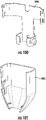
- FIG. 15 depicts shell 210 of multiport 200 of FIG. 5 and FIGS. 16 -18 depict various views of the first portion 210A of shell 210 of FIG. 5 .
- Shells 210 may have any suitable shape, design or configuration as desired.
- the shell 210 of multiport 200 shown in FIG. 15 may include a second end 213 comprising one or more connection ports, pass-through ports, or the like as desired.
- shells 210 may comprise more than two portions if desired.
- multiple portions of the shell 210 may comprise connection ports 236.
- any of the multiports 200 disclosed herein may optionally be weatherproof by appropriately sealing seams of the shell 210 or the connection port insert(s) 230 with the shell 210 using any suitable means such as gaskets, O-rings, adhesive, sealant, welding, overmolding or the like.
- the interface between the connection ports 236 and the dust cap or connector 10 may be sealed using appropriate geometry and/or a sealing element such as an O-ring or gasket.
- the input connection port may be weatherproofed in a suitable manner depending on the configuration such as a gasket, or O-ring with an optical connection or a heat shrink, adhesive or the like when using a input tether. If the multiport 200 is intended for indoor applications, then the weatherproofing may not be required.
- Multiport 200 may comprise integrated mounting features.
- shell 210 depicts mounting features 210MF disposed near first and second ends 212,214 of shell 210.
- Mounting feature 210MF adjacent the first end 212 is a mounting tab and the mounting feature 210MF adjacent the second end 214 is a through hole.
- mounting features 210MF may be disposed at any suitable location on the shell 210 or connection port insert 230.
- multiport 200 also depicts a plurality of mounting features 210MF configured as passageways disposed on the lateral sides.
- the user may simply use a fastener such as a zip-tie threaded thru these lateral passageways for mounting the multiport 200 to a wall or pole as desired.
- Multiport 200 may have the input connection port 260 disposed in any suitable location.
- multiport 200 may have the input connection port 260 disposed in an outboard position of the connection port insert 230.
- the input connection port 260 may be disposed in a medial portion of the multiport if desired.
- shells 210 may comprise at least one support 210S or fiber guide 210G disposed within cavity 216, thereby providing crush support for the multiport and resulting in a robust structure.
- one or more of securing feature passageways 245 are arranged transversely to a longitudinal axis LA of the multiport 200 or shell 210.
- Multiport may include a fiber tray or fiber guide/supports that is a discrete component that may attach to the shell 210 or connector port insert 230; however, fiber guides may be integrated with the shell if desires.
- FIG. 17 shows shell 210 comprising fiber guides 210G for organizing and routing optical fibers 250. Fiber guides 210G may also act as support 210S for providing crush strength to the shell 210 if they have a suitable length.
- FIGS. 19-26 depict the assembly of multiport 200 of FIG. 5 .
- FIGS. 19-26 depict the assembly of the multiport 200 of FIG. 5 .
- FIG. 19 depicts the securing feature 310 being aligned for installation into the securing feature passageway 245 of the first portion 210A of shell 210.
- keying features 310K of securing feature 310 are aligned with the features of the securing feature passageway 245, which only allow assembly in one orientation for the correct orientation of the locking feature 310L.
- FIG. 20 shows adapter 230A being aligned for installed into the saddle 210D of first portion 210A of shell 210.
- the resilient member 230RM of adapter 230A is abutted against the rear ledge 210RL of saddle 210D, thereby compressing the resilient member 230RM and providing a suitable forward-biasing force to the adapter 230A as shown in FIG. 21 .
- retainer 240 may be secured to first portion 210A for securing the adapters 230A in place as depicted in FIG. 22 .
- Retainer 240 may include securing features 240A for a robust assembly, but fasteners or other suitable structure may be used to attach the retainer 240
- FIG. 23 depicts rear connector 252 comprising a ferrule 252F for securing and mating one or more to optical fibers 250 aligned with adapter 230A along with other components before being assembled.
- Rear connector 252 is a SC connector as known in the art, but any suitable device having a ferrule or other structure for receiving and aligning one or more optical fibers 250 from inside the multiport is possible.
- FIG. 23A is an assembled sectional view showing the rear connector 252 attached to the adapter 230A with the ferrule sleeve retainer 230R and the ferrule sleeve 230FS installed for aligning mating ferrules.
- Resilient member 230RM is disposed over a barrel of adapter 230A and seated on the flange of adapter 230A as depicted. Then, ferrule sleeve retainer 230R and ferrule sleeve 230FS are aligned and disposed between connector 252 the adapter 230A for assembly as shown in FIG. 23 .
- adapter 230A comprises a plurality of resilient arms 230RA comprising securing features 230SF. Securing features 230SF cooperate with protrusions on the housing of rear connector 252 for retaining the rear connector 252 to the adapter 230A with the ferrule sleeve retainer 230R and ferrule sleeve 230FS therebetween.
- FIG. 23A is a sectional view showing the attachment of the rear connector 252 with the adapter 230A with ferrule sleeve retainer 230R and the ferrule sleeve 230FS therebetween.
- Ferrule sleeves 230FS are used for precision alignment of mating ferrules between rear connectors 252 and connector 10.
- FIG. 24 is a perspective view of the rear connector 252 with the ferrule sleeve retainer 230R and ferrule sleeve 230FS fitted over ferrule 252F before being attached to adapter 230A.
- FIGS. 24A-24I depict alternative rear connectors that may be used with devices disclosed herein.
- FIGS. 24A-24D depict various views of a simplified construction for the rear connector 252 for use with adapter 230A.
- FIGS. 24A-24D show a simple ferrule 252F comprising protrusions 252P that cooperate with securing features 230SF disposed on the resilient arms 230RA of adapter 230A for securing the same.
- the ferrule sleeve 230FS is disposed between ferrule 252F and the adapter 230A as shown.
- 24E and 24F show rear connector 252 having a ferrule 252F such as an SC connector that cooperates directly with a portion of the multiport such as a shell for securing the same.
- the rear connector 252 is inserted into a portion of the multiport and the ferrule for alignment without a separate adapter.
- the ferrule sleeve 230FS is disposed between rear connector 252 and the multiport structure as shown.
- a portion of the rear connector 252 is secured in a multiport saddle 210D and secured between the first portion 210A and the second portion 210B of shell 210 in this embodiment.
- FIGS. 24G-24I depict rear connector 252 having a ferrule 252F and a ferrule socket 252FS that holds and aligns the ferrule 252F.
- This rear connector cooperates directly with a portion of the multiport such as a shell for securing the same.
- the ferrule socket 252FS has one or more tabs (not numbered) that fit into a portion of the multiport such as a first portion 210A of shell 210.
- the ferrule socket 252FS is secured in a multiport saddle 210D. As best shown in FIG. 24I , the ferrule socket 252FS is secured between the first portion 210A and the second portion 210B of shell 210.
- FIG. 25 is a longitudinal cross-sectional view of a rear portion of the connection port 236 of the multiport 200 of FIG. 5 with the rear connector 252 of FIG. 24 attached to the adapter 230A.
- FIG. 26 is a partial assembled view of multiport 200 of FIG. 25 showing the respective securing feature resilient members 310R placed on a bottom portion of securing feature 310 within the first portion 210A of the shell 210 before the second portion 210B of shell 210 is attached to trap the securing feature resilient members 310R in place.
- Securing feature 310 may have a bottom recess 310BR for seating the securing feature resilient members 310R and centering the restoring force on the securing feature 310 as best shown in FIG. 14 .
- the second portion 210B of shell 210 may be attached to the first portion 210A is a suitable fashion using a sealing element 290 or not.
- Multiports 200 disclosed with shells 210 and/or connector port inserts 230 allow relatively small multiports 200 having a relatively high-density of connections along with an organized arrangement for connectors 10 attached to the multiports 200.
- Shells have a given height H, width W and length L that define a volume for the multiport as depicted in FIG. 3A and 4A .
- shells 210 of multiport 200 may define a volume of 800 cubic centimeters or less, other embodiments of shells 210 may define the volume of 400 cubic centimeters or less, other embodiments of shells 210 may define the volume of 100 cubic centimeters or less as desired.
- multiports 200 comprise a connection port insert 230 having a port width density of at least one connection port 236 per 20 millimeters of width W of the multiport 200. Other port width densities are possible such as 15 millimeters of width W of the multiport. Likewise, embodiments of multiports 200 may comprise a given density per volume of the shell 210 as desired.
- Table 1 compares representative dimensions, volumes, and normalized volume ratios with respect to the prior art of the shells (i.e., the housings) for multiports having 4, 8 and 12 ports as examples of how compact the multiports of the present application are with respect to convention prior art multiports.
- Table 1 compares examples of the conventional prior art multiports such as depicted in FIG. 1 with multiports having a linear array of ports.
- the respective volumes of the conventional prior art multiports of FIG. 1 with the same port count are on the order of ten times larger than multiports with the same port count as disclosed herein.
- the multiport may define a volume of 400 cubic centimeters or less for 12-ports, or even if double the size could define a volume of 800 cubic centimeters or less for 12-ports.
- Multiports with smaller port counts such as 4-ports could be even smaller such as the shell or multiport defining a volume of 200 cubic centimeters or less for 4-ports, or even if double the size could define a volume of 100 cubic centimeters or less for 4-ports.
- Devices with sizes that are different will have different volumes from the explanatory examples in Table 1 and these other variations are within the scope of the disclosure.
- the size (e.g., volume) of multiports of the present application are much smaller than the conventional prior art multiports of FIG. 1 .
- the multiports of the present application do not have the issues of the conventional prior art multiports depicted in FIG. 2 .
- the examples of Table 1 are for comparison purposes and other sizes and variations of multiports may use the concepts disclosed herein as desired.
- the connectors 10 that cooperate with the multiports have locking features 20L that are integrated into the housing 20 of the connectors.
- the locking features for securing connector 10 are integrally formed in the housing 20 of the connector, instead of being a distinct and separate component like a coupling nut of a conventional hardened connector used with conventional multiports.
- Conventional connectors for multiports have threaded connections that require finger access for connection and disconnecting. By eliminating the threaded coupling nut (which is a separate component that must rotate about the connector) the spacing between conventional connectors may be reduced.
- Table 1 Comparison of Conventional Multiport of FIG. 1 with Multiports of Present Application Multiport Type Port Count Dimension LxWxH (mm) Volume (cm 3 ) Normalized Volume Ratio Prior Art 4 274 ⁇ 66 ⁇ 73 1320 1.0
- FIG. 1 8 312 ⁇ 76 ⁇ 86 2039 1.0 12 381 ⁇ 101 ⁇ 147 5657 1.0
- FIGS. 27 and 28 depict perspective views of another explanatory device 200 configured as a multiport that comprises at least one connection port 236 along with a securing feature 310 comprising more than one component.
- Multiports 200 with securing features having more than one component such as shown in FIGS. 27 and 28 may have a construction similar to that shown in FIGS. 3A and 3B with the connection ports 236 being a portion of the connection port insert 230 or a construction similar to that shown in FIGS. 4A and 4B with the connection ports 236 as a portion of shell 210 as desired.
- FIGS. 28A-28E depict a device such as multiport 200 that comprises connection port insert 230 having at least one connection port 236 and FIGS. 29-56 depict device such as multiport 200 comprising a connection port 236 as a portion of the shell 210 with securing features 310 comprising more than one component.
- the description of these devices with the securing feature 310 comprising more than one component will describe differences in the designs for the sake of brevity.
- Multiports 200 of FIGS. 27 and 28 comprise one or more optical connection ports 236 defined by one or more optical connector openings 238 disposed in a shell 210 of the multiport 200 for receiving one or more connectors 10 according to the concepts disclosed.
- FIG. 27 depicts a connector 10 aligned for insertion into one of the connection ports 236 and
- FIG. 28 depicts a plurality of connectors 10 retained within respective connection ports 236.
- Multiport 200 using securing features 310 comprising multiple components may also comprise an input port 260, splitter, tether, or other suitable components or features as desired.
- Multiport 200 of FIGS. 27 and 28 is similar to multiport 200 of FIGS. 4A and 4B , except it uses a securing feature 310 comprising more than one component as shown in FIG. 36 .
- the multiport 200 of FIGS. 28A-28E is similar to multiport 200 of FIGS. 3A and 4B , except it uses a securing feature 310 comprising more than one component as best shown in FIG. 28D .
- the securing feature 310 comprises an actuator 310A and a securing feature member 310M.
- securing feature member 310M comprises an opening may be elastically deformed by actuator 310A (or other structure) when pushed (or upon insertion of a suitable connector 10 into connection port 236) and the securing feature member 310M springs back to engage a suitable portion of connector 10 such as locking feature 20L of connector housing 20 when the actuator 310A is released or when connector 10 is fully-seated within the connection port 236 as will discussed in more detail.
- the securing member 310M comprises a locking feature 310L formed by one or more arms 310AM
- securing feature member 310M of securing feature 310 is suitable for retaining connector 10 in connection port 236 as discussed herein.
- securing features 310 comprising more than one component for the devices disclosed.
- Multiport 200 of FIGS. 27 and 28 comprise one or more connection ports 236 and the one or more securing feature passageways 245 as a portion of the shell 210.
- multiports 200 of FIGS. 28A-28E comprises the one or more connection ports 236 and the one or more securing feature passageways 245 as a portion of the connection port insert 230 as discussed hererin.
- FIGS. 27 and 28 depict multiport 200 comprising a shell 210 comprising a body 232 with one or more connection ports 236 disposed on a first end or portion 212 with each connection port 236 comprising a respective optical connector opening 238.
- the optical connector openings 238 extend from an outer surface 234 of shell 210 into a cavity 216 and define a connection port passageway 233.
- One or more respective securing feature passsageways 245 extend from the outer surface 234 of the shell 210 to the respective connection port passageways 233.
- a plurality of security features 310 are associated with the respective plurality of connection port passageways 233 and the plurality of securing features 310 are disposed within portions of respective securing feature passageways 245.
- FIGS. 28A-28E are views another multiport 200 comprising connection port insert 230 that receives an actuator 310A and a securing feature member 310M of the securing feature 310 similar to multiport 200 of FIGS. 27 and 28 .
- this embodiment is different in the manner which the securing feature 310M is assembled to the connection port insert 230 from a rear side and secured with a securing feature locking member 310LM at the bottom of the securing feature member 310M.
- the securing feature members 310M are individually placed into the connection port insert 230 from the rear and engage a portion of the actuator 310A for keeping the actuators 310A within the respective securing feature passageways 245.
- the securing feature 310 of this embodiment further includes a securing feature resilient member 310R for biasing the actuator 310A.
- the fiber tray 285 may be used as a retainer for securing the adapters 230A as well.
- FIG. 29 depicts a bottom perspective view of multiport 200 of FIGS. 27 and 28 .
- shell 210 is formed by a first portion 210A and a second portion 210B.
- FIG. 29 shows the second portion 210B of shell 210 removed from the first portion 210A for showing the internal construction of multiport 200.
- Multiport 200 is depicted with the rear connectors 252 and the optical fibers 250 removed for clarity purposes in FIG. 29 .
- FIG. 30 is a partially exploded view of the multiport of FIGS. 27 and 28 showing a single rear connector 252 and having the optical fibers 250 removed for clarity.
- Rear connectors 252 are aligned and sized for fitting into one or more of the respective connector port passageways 233 from the rear portion 237 of passageway 233 within the cavity 216 of shell 210, and the plurality of rear connectors 252 are associated with one or more of the plurality of optical fibers 250.
- each of the respective rear connector 252 aligns and attaches to the shell 210 from the rear portion 237 in a suitable matter.
- rear connectors 252 may take any suitable form from a simple ferrule that attaches to standard connector type inserted into an adapter.
- FIGS. 31 and 32 are partial longitudinal cross-sectional views respectively depicting the optical connection port 236 of the multiport 200 of FIGS. 27 and 28 without connector 10 retained therein for showing details of securing feature 310.
- FIG. 33 is a longitudinal cross-sectional views of the multiport 200 of FIGS. 27 and 28 with connector 10 disposed and retained within connection port 236 by securing feature 310.
- FIG. 34 is a transverse cross-sectional view of a portion of the multiport 200 of FIGS. 27 and 28 taken through the securing features 310 showing details of the construction and operation for securing features 310 comprising more than one component.
- FIGS. 35 is a detailed longitudinal horizontal cross-sectional view of the securing feature 310 receiving and retaining connector 10 within the connection port 236. Specifically, the arms of the securing member 310M engage a locking feature 20L (e.g., a groove) that is integrally-formed on the housing 20 of the connector 10.
- FIG. 36 is a detailed perspective view of the securing features of the multiport of FIGS. 27 and 28 removed from the shell with connector 10 being retained by one of the securing features 310.
- Securing feature 310 comprises actuator 310A and securing member 310M.
- Securing member 310M comprises an opening between its arms 310AM that may be elastically deformed by actuator 310A when translated (i.e., pushed) or upon insertion of a suitable connector 10 into connection port 236 by spreading (i.e., translating) the arms of the securing member 310M outward.
- the arms 310AM of the securing member 310M springs back to engage a suitable portion of connector 10 such as locking feature 20L of connector housing 20 or move the actuator 310A to a normal position.
- the arms 310AM have an edge portion that act as a locking feature 310L for the suitable connector 10.
- the edge portions of arms 310AM engage the locking feature 20L of the connector housing 20 for securing the connector 20.
- the arms 310AM and locking features 310L on the arms 310AM are translated outward.
- actuator 310A comprises a wedge 310W that pushes into a head end 310H of securing member 310M, thereby elastically deflecting the arms 310AM of securing member 310M outward for releasing connector 10.
- the securing member 310M or actuators 310A of securing feature 310 may comprise a variety of different constructions.
- the securing features 310 comprising more than one component may be biased by a securing feature resilient member 310RM if desired.
- securing feature resilient member 310RM may bias the actuator 310A toward a secure position.
- the securing feature resilient member may bias the securing member 310M.
- FIGS. 37-39 are various perspective views of the actuator 310A of the securing feature 310 of the multiport 200 shown in FIGS. 27 and 28 .
- Actuator 310A may include a sealing member 310S disposed above the connector port passageway 233 for keeping dirt, debris and the like out of portions of the multiport 200. Sealing member 310S is sized for the retention groove 310RG in the actuator 310A and the securing feature passageway 245 for sealing.
- Actuator 310A may also be shaped to have one or more guides 310G that cooperate with the shell 210 or connection port insert 230 for keeping proper rotational orientation of the wedge 310W within the respective securing feature passageway 245 during translation.
- Actuator 310A may also comprise a stop surface 310SS for inhibiting overtravel or the actuator 310A from being removed from the multiport 200 when assembled.
- Actuator 310A may also be a different color or have a marking indicia for identifying the port type. For instance, the actuator 310A may be colored red for connection ports 236 and the actuator 310A for the input connection port 260 may be colored black. Other color or marking indicia schemes may be used for pass-through ports, multi-fiber ports or ports for split signals.
- FIGS. 40-43 are various views of securing member 310M for explaining details of the design.
- FIG. 40 is a perspective view of the securing member blank for forming the securing feature 310M depicted in FIGS. 41-43 .
- Securing member 310M may be formed from any suitable material such as a spring steel and have a suitable geometry for retaining a connector 10.
- FIGS. 41-43 are various perspective views showing the structure of securing member 310M.
- securing member 310M comprises arms 310AM that define an opening (not numbered) therebetween along with a head end 310H formed at the ends of the arms 310AM The opening (not numbered) between the arms 310AM is sized for cooperating with a suitable connector 10.
- Arms 310AM may comprise tabs 310T that are curved for aiding the engagement of the connector 10 with the securing member 310M upon insertion and allowing a smoother pushing and translation of the arms 310AM outward as connector 10 is inserted into connection port 236.
- the head end 310H may also be formed with a suitable shape that cooperates with the actuator 310A.
- the securing feature 310 may comprises more than one component for translating from a retain position (RP) to an open position (OP) as a suitable connector 10 is inserted into the connection port 236.
- the securing feature 310 automatically moves to the retain position (RP) since the arms 310AM are biased to the retain position.
- RP retain position
- FIGS. 44 and 45 are bottom and top perspective views showing the optical fiber tray or guide 285 that is placed into shell 210A of multiport 200.
- FIG. 46 is a bottom perspective view of a first portion of the shell of the multiport 200 and
- FIG. 47 is a perspective view of the second portion of the shell of the multiport of 200 for showing details.
- FIGS. 48 and 49 respectively are partially exploded and assembled views of a securing feature sub-assembly 310SA for a portion of the securing feature 310.
- the securing members 310M may be placed into a housing formed by one or more housing portions 310HH for maintaining the proper orientation of the securing features.
- the securing feature sub-assembly 310SA also allows for easier assembly of multiple securing members 310M into the devices.
- the housing portions 310HH may have suitable geometry for keeping the securing members in the desired orientation.
- FIG. 49 depicts the securing feature sub-assembly 310SA ready for placing into the device.
- securing feature 310 depicts the components of securing feature 310 being installed into the first portion of the shell of FIG. 46 .
- the actuators 310A of the securing features are installed into the respective securing feature passageways of the shell 210A with the wedge 310W facing up.
- the securing feature sub-assembly 310SA may be placed into a cavity 210C of the securing feature passageway formed within shell 210A. Consequently, the actuators 310A are aligned and positioned with respective securing members 310M of the securing features.
- FIGS. 51-52 show the optical fiber tray or guide 285 being installed into the first portion of the shell of the multiport 200.
- the devices may also comprises a fiber guide or tray (not numbered) integrated with the body 232.
- Fiber tray 285 may include one or more protrusions 285P that aid alignment and may also provide strength for the device to withstand any crushing forces.
- Including supports for multiports 200 greatly improves the strength between the opposing walls, and the supports may be included on other components such as the shell 210 such as 210P or the integrated in a separate fiber tray such as depicted.
- Supports or protrusions may also act as fiber routing guides to inhibit tight bending or tangling of the optical fibers and aid with slack storage of optical fibers 250.
- Other embodiments may also comprises one or more fiber routing guides 230G or supports 230S.
- FIG. 53 is a perspective view of the adapters 230A and retainer 240 being aligned for installation into the first portion 210A of the shell 210 and
- FIG. 54 is a perspective view of the plurality of adapters and an adapter retainer assembled into the first portion 210A of the shell 210.
- FIG. 55 shows the second portion 210B of the shell 210 being aligned with the first portion 210A of the shell 210 with the rear connectors 252 and optical fibers 250 removed for clarity.
- FIG. 56 is a detailed sectional view showing details of the interlocking features between the first portion 210A and the second portion 210B of the shell 210.
- portions of the multiport may have a tongue 210T and groove 210G construction for alignment or sealing of the device.
- FIGS. 57-59 depict perspective views of another securing feature 310 comprising securing member 310M for use with an actuator 310A.
- FIG. 60 depicts a suitable connector housing 20 for the securing member 310M of FIGS. 57-59 . As shown, the connector housing 20 has the locking feature 20L disposed forward of the O-ring 65.
- FIG. 57 is a perspective view of the securing member blank for forming the securing member 310M depicted in FIGS. 58 and 59 .
- FIGS. 61 and 62 are perspective views of the securing feature 310 cooperating with the connector housing 20 of FIG. 60 .
- the securing member 310M may be secured in the device using locking member 310LM.
- FIGS. 63-65 depict perspective views of yet another securing member 310M for securing features 310 comprising more than one component along with a suitable connector housing 20 for cooperating with the securing feature 310.
- FIG. 63 shows securing member 310M formed from a wire.
- this securing member 310M comprises arms 310AM that define an opening (not numbered) therebetween along with a head end 310H formed at the ends of the arms 310AM The opening (not numbered) between the arms 310AM is sized for cooperating with a suitable connector 10.
- the head end 310H of the arms 310AM are received in a portion of actuator 310A as shown in FIG. 65 .
- This securing feature 310 may also be biased by a resilient member 310R.
- FIGS. 66-68 depict perspective views of yet another securing feature comprising more than one component.
- the securing member 310M is inverted so that the head end 310H cooperates with a portion of the multiport for translating the arms 310AM compared with other embodiments.
- a portion of the multiport such as connector port insert of shell comprises a wedge 210W as shown in FIG. 69 .
- FIG. 66 depicts the actuator 310A attached to a base 310B of the securing member 310M and the head end 310H disposed on the opposite end and
- FIG. 67 shows that the base 310B may have aperture for securing the actuator 310A to the securing member 310M.
- FIG. 68 shows connector housing 20 cooperating with the arms 310AM for securing the connector 10.
- This securing feature 310 may also be biased by a resilient member 310R as shown.
- FIG. 69 shows how the head end 310H of securing member 310M cooperates with wedge 210W of the multiport for translating the arms 310AM outward when the acutator 310A translates downward.
- FIGS. 70-72 depict views of yet another securing feature comprising more than one component.
- FIG. 70 is a sectional view of another securing feature 310 comprising securing member 310M for use with an actuator 310A that provides a reduced height compared with other embodiments.
- This securing member 310M comprises arms 310AM that define an opening (not numbered) therebetween along with a head end 310H formed at the ends of the arms 310AM. Head end 310H of this securing member 310M has the ends curled in and downward and the actuator 310A positions the wedge 310W further upward into the acutator 310A footprint as shown in FIG. 70 resulting in a construction that has a reduced height and allowing the device to reduce its height as well.
- FIG. 70 is a sectional view of another securing feature 310 comprising securing member 310M for use with an actuator 310A that provides a reduced height compared with other embodiments.
- This securing member 310M comprises arms
- FIG. 71 depicts a suitable connector housing 20 for the securing member 310M with the actuator 310A translated to an open position for releasing the connector.
- the connector housing 20 has the locking feature 20L disposed forward of the groove for the O-ring 65.
- FIG. 72 shows the notch 310N that allows the wedge 310W to be incorporated further into the body of the actuator 310A.
- FIG. 73 is a sectional view of a further securing feature 310 arranged at an angle relative to the longitudinal axis LA of the connection port 236.
- This securing feature 310 comprises securing member 310M and actuator 310A disposed in a securing feature passageway 245 that is angled with respect to the longitudinal axis LA of the connection port 236.
- connector 10 has a connector housing 20 with the locking feature 20L that is angled with respect to the longitudinal axis of the connector. Similar concepts may be used with as a portion of the shell or the connection port insert as well as a monolithic securing feature 310.
- FIG. 74 depicts a device 200 comprising the actuator 310A of the securing feature 310 disposed in a horizontal direction with respect to the longitudinal axis LA of the connection port 236.
- FIG. 74A is a perspective views showing a securing feature construction without the multiport and securing connector 10.
- This securing feature 310 comprises actuator 310A and securing member 310M.
- This securing member 310 comprises bore 310B for receiving the connector 10 therethrough. Bore 310B may have any suitable locking feature 310L (not visible) for cooperating with connector 10.
- Securing member 310M comprises a securing member push 310P.
- Securing member push 310P is configured as a ramp for translating the securing member 310M as the actuator 310A is translated toward the securing member 310M.
- Actuator 310A comprises a complimentary surface that cooperates with securing member push 310P.
- Securing feature resilient member 310RM may bias the actuator. Consequently, the securing member 310M may translate from a secure position to an open position.
- This securing feature 310 may have other features as disclosed herein as well.
- FIG. 74B depicts the securing feature 310 of FIG. 74A being placed into the device.
- FIGS. 75-82 depict another device such as a multiport 200 similar to FIG. 74 the actuator 310A of the securing feature 310 arranged in a direction that is generally aligned and offset from the longitudinal axis of the connector port 236.
- This multiport 200 of FIGS. 75-82 is also similar to the embodiment of FIGS. 27 and 28 and shown in cross-section of the connection port 236 at FIG. 33 since the securing members 310M are disposed in a sub-assembly 310SA. Since the actuator 310A is generally positioned horizontal with the connection port 236 the securing member 310M is modified for cooperating with the different translation direction of the actuator 310A.
- FIGS. 75 and 77 the wedge 310W of actuator 310A moves in a horizontal direction as depicted in FIGS. 75 and 77 and the head end 310H moves to the optical connector opening 238 side of the securing member 310M.
- This embodiment shows the securing members 310M disposed in a securing feature sub-assembly 310SA that is positioned in a cavity 210C of the securing feature passageway 245 formed within shell 210A as shown in FIG. 76 .
- FIG. 78 depicts first portion 210A of shell 210 from the inside without components installed and
- FIG. 79 depicts actuators 310A placed into a portion of the securing feature passageway 245 of first portion 210A of shell 210.
- Actuators 310A may have features as disclosed herein.
- FIGS. 80 and 81 depict that this embodiment has the securing member housing 310HH is formed as a single component but may the securing member housing 310HH may be formed from multiple components if desired.
- FIG. 82 depicts a perspective view of the securing member 310M for this embodiment.
- Arms 310AM may comprise tabs 310T that are curved for aiding the engagement of the connector 10 with the securing member 310M upon insertion and allowing a smoother pushing and translation of the arms 310AM outward as connector 10 is inserted into connection port 236.
- the head end 310H may also be formed with a suitable shape that cooperates with the actuator 310A during translation.
- FIG. 83 is a top view of another multiport 200 having connection ports 236 (or connection port passageways 238) associated with securing features that are disposed on both a first (or portion) end and a second (or portion) end of the device.
- This concept may be used with devices that use a connection port insert 230 or connection ports that are formed as a portion of the shell.
- FIGS. 84-88 are various views of another multiport 200 having connection ports 236 disposed in more than one row according to the concepts disclosed.
- This multiport 200 comprises twelve connection ports 236 and one input connection port 260 in a relatively dense arrangement and is advantageous for use where space is at a premium such as in a pedestal.
- This multiport 200 comprises shell 210 comprising two portions 210A,210A' with portion 210A comprising an input connection port 260. Both portions of shell 210 comprise connection ports 236 and features for securing features 310 as disclosed herein.
- the portions 210A,210A' of shell 210 comprise a construction similar to the construction of the multiport 200 of FIGS.
- the portions 210A, 210A' of shell 210 are configured to be secured back-to-back so the open portions of the portions align, thereby forming a common cavity 216 between the portions 210A,210A' of shell 210.
- FIGS. 89-91 are various views of multiport 200 comprising connection ports 236 disposed in stacked rows and laterally offset in a stair-step fashion.
- This multiport 200 also comprises twelve connection ports 236 and one input connection port 260 in a relatively dense arrangement.
- This multiport 200 has shell 210 comprising first portion 210A, second portion 210B', and third portion 210B.
- the first portion 210A of shell comprises the input connection port 260, other portions could comprise an input connection port as well.
- Both portions 210A, 210B'of shell 210 comprise a connection ports 236 and features for securing features 310 as disclosed herein.
- First portion 210A and third portion 210B sandwich second portion 210B' of shell 210 therebetween.
- the portion 210B' of shell 210 has a cavity that is open to both first shell 210A and third shell 210B.
- Fiber tray 285 may be used to arrange optical fibers 250 on both sides for aiding assembly and simplicity.
- the portions 210A,210B' of shell 210 comprise a construction similar to the construction of the multiport 200 of FIGS. 27 and 28 for the securing features 310 and connection ports 236 so details of the construction will not be repeated again for the sake of brevity.
- FIGS. 92-96 are various views of still another device having connection ports 236 disposed in stacked rows that are offset and arranged on an angled surface in a stair-step fashion similar to the device of FIGS. 89-91 .
- This multiport 200 also comprises twelve connection ports 236 and one input connection port 260 in a relatively dense arrangement.
- This multiport 200 has shell 210 comprising first portion 210A, second portion 210B', and third portion 210B similar to the shell of FIGS. 89-91 .
- first portion 210A and second portion 210B' arrange the connection ports 236 on an angled surface.
- First portion 210A and third portion 210B sandwich second portion 210B' of shell 210 therebetween.
- the portion 210B' of shell 210 has a cavity that is open to both first shell 210A and third shell 210B as shown in FIG. 93 .
- FIGS. 94-96 depict perspective views of the first portion 210A and the second portion 210B' of shell 210.
- the portions 210A,210B' of shell 210 comprise a construction similar to the construction of the multiport 200 of FIGS. 27 and 28 for the securing features 310 and connection ports 236 so details of the construction will not be repeated again for the sake of brevity.
- FIGS. 97 and 98 are perspective views of a first cover 200C that may be used with multiports 200. This cover 200C cooperates with mounting features 210MF formed on multiport 200. Specifically, arms (not numbered) of cover 200C engage the respective mounting features 210MF disposed on the multiport as shown in FIG. 97 .
- FIG. 98 shows that cover 200C essentially hides the securing features 310 when installed. Cover 200C may be secured in any suitable fashion.
- FIGS. 99-101 are perspective views of a second cover 200C that cooperates with a bracket 200B that may be used multiports 200. This cover 200C cooperates with bracket 200B as shown in FIG. 99 .
- FIG. 98 shows bracket 200B and when cover 200C is attached to bracket 200B its essentially hides the securing features 310.
- FIG. 101 shows the features on the inside portion of cover 200C that cooperate with the bracket 200B for securing the same.
- FIG. 102 is a perspective view of a wireless device 500 having a similar construction to the concepts disclosed herein and comprising at least one connector port 236 associated with securing member 310.
- Wireless device 500 may comprise one or more connection ports 236 disposed on connection port insert as represented by parting line PL1 or one or more connection ports 236 disposed on the portion of shell 210 as represented by parting line 2.
- Wireless device 500 may have an input port that includes power and may have electronics 500E (not visible) disposed with in the cavity (not visible) of the device.
- FIG. 103 is a perspective view of a closure 700 comprising at least one connector port 236 and associated securing member 310.
- closure 700 may comprise one or more connection ports 236 disposed on connection port insert as represented by parting line PL1 or one or more connection ports 236 disposed on the portion of shell 210 as represented by parting line 2.
- Closure 700 may have one or more input ports or include other components disposed with in the cavity (not visible) of the device.
- connection port insert 230 comprises inserting a connection port insert 230 into an opening 214 disposed in a first end 212 of an shell 210 so that at least a portion of the connection port insert 230 fits into the opening 212 and is disposed within a cavity 216 of the shell 210; and wherein the connection port insert 230 comprises a body 232 having a front face 234 and at least one connection ports 236 with the connection port 236 having an optical connector opening 238 extending from the front face 234 into the connection port insert 230 with a connection port passageway 233 extending through part of the connection port insert to a rear portion 237.
- One method comprises routing a plurality of optical fibers 250 from one or more rear portions 237 of a plurality of connection ports 236 of a connection port insert 230 so that the plurality of optical fibers 250 are available for optical communication at an input connection port 260 of the connection port insert 230.
- connection port insert 230 into an opening 214 disposed in a first end 212 of a shell 210 so that at least a portion of the connection port insert 230 fits into the opening 212 and is disposed within a cavity 216 of the shell 210; and wherein the connection port insert 230 comprises a body 232 having a front face 234 and a plurality of connection ports 236 with each connector port 236 having an optical connector opening 238 extending from the front face 234 into the connection port insert 230 with a connection port passageway 233 extending through part of the connection port insert to the rear portion 237.
- the methods disclosed may further include installing at least one securing feature 310 into a multiport 200 so that the at least one securing feature 310 is associated with connection port 236.
- the securing feature 310 may translate between an open position OP and a closed position CP.
- the method may include translating the securing feature 310 for moving the securing feature 310 to the open position OP and the securing feature 310 is biased to closed position CP.
- the disclosure covers at least the following aspects:
- connection port insert may be configured as individual sleeves that are inserted into a passageway of a device, thereby allowing the selection of different configurations of connector ports for a device to tailor the device to the desired external connector. All such equivalent embodiments and examples are within the spirit and scope of the disclosure and are intended to be covered by the appended claims. It will also be apparent to those skilled in the art that various modifications and variations can be made to the concepts disclosed without departing from the spirit and scope of the same. Thus, it is intended that the present application cover the modifications and variations provided they come within the scope of the appended claims and their equivalents.
Abstract
Description
- This application claims the benefit of
U.S. Application No. 62/451,221, filed on January 27, 2017 U.S. Application No. 62/428,212, filed on November 30, 2016 U.S. Application No. 62/428,219, filed on November 30, 2016 U.S. Application No. 62/428,224, filed on November 30, 2016 U.S. Application No. 62/428,230, filed on November 30, 2016 U.S. Application No. 62/451,234, filed on January 27, 2017 U.S. Application No. 62/526,011, filed on June 28, 2017 U.S. Application No. 62/526,018, filed on June 28, 2017 U.S. Application No. 62/428,234, filed on November 30, 2016 U.S. Application No. 62/428,244, filed on November 30, 2016 U.S. Application No. 62/428,252, filed on November 30, 2016 U.S. Application No. 62/526,195, filed on June 28, 2017 - The disclosure is directed to devices providing at least one optical connection port along with methods for making the same. More specifically, the disclosure is directed to devices such as multiports comprising a keyed-connection port and a securing feature associated with the connection port for securing an optical connector along with methods of making the same.
- Optical fiber is increasingly being used for a variety of applications, including but not limited to broadband voice, video, and data transmission. As bandwidth demands increase optical fiber is migrating deeper into communication networks such as in fiber to the premises applications such as FTTx, 5G and the like. As optical fiber extended deeper into communication networks the need for making robust optical connections in outdoor applications in a quick and easy manner was apparent. To address this need for making quick, reliable, and robust optical connections in communication networks hardened fiber optic connectors such as the OptiTap® plug connector were developed.
- Multiports were also developed for making an optical connection with hardened connectors such as the OptiTap. Prior art multiports have a plurality of receptacles mounted through a wall of the housing for protecting an indoor connector inside the housing that makes an optical connection to the external hardened connector of the branch or drop cable.
- Illustratively,
FIG. 1 shows a conventional fiberoptic multiport 1 having an input fiber optic cable 4 carrying one or more optical fibers to indoor-type connectors inside ahousing 3. Themultiport 1 receives the optical fibers intohousing 3 and distributes the optical fibers to receptacles 7 for connection with a hardened connector. Thereceptacles 7 are separate assemblies attached through a wall ofhousing 3 of themultiport 1. Thereceptacles 7 allow mating with hardened connectors attached to drop or branching cables (not shown) such as drop cables for "fiber-to-the-home" applications. During use, optical signals pass through the branch cables, to and from the fiber optic cable 4 by way of the optical connections at thereceptacles 7 ofmultiport 1. Fiber optic cable 4 may also be terminated with a fiberoptic connector 5. Multiports 1 allowed quick and easy deployment for optical networks. - Although, the
housing 3 of theprior art multiport 1 is rugged and weatherable for outdoor deployments, thehousings 3 ofmultiport 1 are relatively bulky for mountingmultiple receptacles 7 for the hardened connector on thehousing 3.Receptacles 7 allow an optical connection between the hardened connector such as the OptiTap male plug connector on the branch cable with a non-hardened connector such as the SC connector disposed within thehousing 3, which provides a suitable transition from an outdoor space to an protected space inside thehousing 3. -
Receptacle 7 for the OptiTap connector is described in further detail inUS Pat. No. 6,579,014 . As depicted inUS 6,579,014 , the receptacle includes a receptacle housing and an adapter sleeve disposed therein. Thus, the receptacles for the hardened connector are large and bulky and require a great deal of surface array when arranged in an array on thehousing 3 such as shown withmultiport 1. Further, conventional hardened connectors use a separate threaded or bayonet coupling that requires rotation about the longitudinal axis of the connector and room for grabbing and rotating the coupling by hand when mounted in an array on thehousing 3. - Consequently, the
housing 3 of themultiport 1 is excessively bulky. For example, themultiport 1 may be too boxy and inflexible to effectively operate in smaller storage spaces, such as the underground pits or vaults that may already be crowded. Furthermore, having all of thereceptacles 7 on thehousing 3, as shown inFIG. 1 , requires sufficient room for the drop or branch cables attached to the hardened connectors attached to themultiport 1. While pits can be widened and larger storage containers can be used, such solutions tend to be costly and time-consuming. Network operators may desire other deployment applications formultiports 1 such as aerial, in a pedestal or mounted on a façade of a building that are not ideal for theprior art multiports 1 for numerous reasons such as congested poles or spaces or for aesthetic concerns. - Other multiports designs have been commercialized to address the drawbacks of the prior art multiports depicted in
FIG. 1 . By way of explanation,US 2015/0268434 discloses multiports 1' having one ormore connection ports 9 positioned on the end ofextensions 8 that project from the housing of the multiport 1' such as depicted inFIG. 2 .Connection ports 9 of multiport 1' are configured for mating directly with a hardened connector (not shown) such as an OptiTap without the need to protect thereceptacle 7 within a housing like theprior art multiport 1 ofFIG. 1 . - Although, these types of multiport designs such as shown in
FIG. 2 and disclosed inUS 2015/0268434 allow the device to have smaller footprints for the housing 3', these designs still have concerns such as the space consumed by the relativelylarge ports 9 and associated space requirements of optical connections between the ports and hardened connector of the drop cables along with organizational challenges. Simply stated, theports 9 on theextensions 8 of the multiport 1' and the optical connections betweenports 9 and hardened connector occupy significant space at a location a short distance away from the multiport housing 3' such as within a buried vault or disposed on a pole. In other words, a cluster ofoptical ports 9 of multiport 1' are bulky or occupy limited space. The conventional hardened connectors used with multiport 1' also use a separate threaded or bayonet coupling that requires rotation about the longitudinal axis of the connector along with sufficient space for grabbing and rotating the coupling means by hand. Further, there are aesthetic concerns with the prior art multiports 1' as well. - Consequently, there exists an unresolved need for multiports that allow flexibility for the network operators to quickly and easily make optical connections in their optical network while also addressing concerns related to limited space, organization, or aesthetics.
- The disclosure is directed to devices comprising at least one connection port and a securing feature associated with the connection port. Devices that may use the concepts disclosed herein include multiports, closures or wireless devices. Methods of making the devices are also disclosed. The devices can have any suitable construction such as disclosed herein such a connection port that is keyed for inhibiting a non-compliant connector from being inserted and potentially causing damage to the device.
- One aspect of the disclosure is directed to devices or multiports comprising a shell, at least one connection port, at least one securing feature passageway, and at least one securing feature. The at least one connection port is disposed on the multiport with the at least one connection port comprising an optical connector opening extending from an outer surface of the multiport to a cavity of the multiport and defining a connection port passageway. The at least one securing feature is associated with the connection port passageway, where the at least one securing feature is disposed within a portion of the at least one securing feature passageway.
- Another aspect of the disclosure is directed to devices or multiports comprising a shell, at least one connection port, at least one securing feature passageway, at least one securing feature, and at least one securing feature resilient member for biasing a portion of the at least one securing feature. The at least one connection port is disposed on the multiport with the at least one connection port comprising an optical connector opening extending from an outer surface of the multiport to a cavity of the multiport and defining a connection port passageway. The at least one securing feature is associated with the connection port passageway, where the at least one securing feature is disposed within a portion of the at least one securing feature passageway.
- Still another aspect of the disclosure is directed to devices or multiports comprising a shell, at least one connection port, at least one securing feature passageway, at least one securing feature. The at least one connection port is disposed on the multiport with the at least one connection port comprising an optical connector opening extending from an outer surface of the multiport to a cavity of the multiport and defining a connection port passageway. The at least one securing feature is associated with the connection port passageway, where the at least one securing feature is disposed within a portion of the at least one securing feature passageway, and the at least one securing feature is capable of translating within a portion of the at least one securing feature passageway.
- Yet another aspect of the disclosure is directed to devices or multiports comprising a shell, at least one connection port, at least one securing feature passageway, at least one securing feature. The at least one connection port is disposed on the multiport with the at least one connection port comprising an optical connector opening extending from an outer surface of the multiport to a cavity of the multiport and defining a connection port passageway. The at least one securing feature is associated with the connection port passageway, and the at least one securing feature comprises a bore, where the at least one securing feature is disposed within a portion of the at least one securing feature passageway, and the at least one securing feature is capable of translating within a portion of the at least one securing feature passageway.
- A further aspect of the disclosure is directed to devices or multiports comprising a shell, at least one connection port, at least one securing feature passageway, at least one securing feature. The at least one connection port is disposed on the multiport with the at least one connection port comprising an optical connector opening extending from an outer surface of the multiport to a cavity of the multiport and defining a connection port passageway. The at least one securing feature is associated with the connection port passageway, and the at least one securing feature comprises a bore, where the at least one securing feature is disposed within a portion of the at least one securing feature passageway, and the at least one securing feature is capable of translating within a portion of the at least one securing feature passageway wherein the at least one securing feature translates from a retain position to an open position as a suitable fiber optic connector is inserted into the at least one connection port.
- Still another aspect of the disclosure is directed to devices or multiports comprising a shell, at least one connection port, at least one securing feature passageway, at least one securing feature. The at least one connection port is disposed on the multiport with the at least one connection port comprising an optical connector opening extending from an outer surface of the multiport to a cavity of the multiport and defining a connection port passageway. The at least one securing feature is associated with the connection port passageway, and the at least one securing feature comprises a bore and a locking feature, where the at least one securing feature is disposed within a portion of the at least one securing feature passageway, and the at least one securing feature is capable of translating within a portion of the at least one securing feature passageway wherein the at least one securing feature translates from a retain position to an open position as a suitable fiber optic connector is inserted into the at least one connection port.
- Other aspects of the disclosure are directed to devices or multiports comprising a shell, at least one connection port, at least one securing feature passageway, at least one securing feature. The at least one connection port is disposed on the multiport with the at least one connection port comprising an optical connector opening extending from an outer surface of the multiport to a cavity of the multiport and defining a connection port passageway. The at least one securing feature is associated with the connection port passageway, and the at least one securing feature comprises a locking member and an actuator, where the at least one securing feature is disposed within a portion of the at least one securing feature passageway, and the at least one securing feature translates from a retain position to an open position as a suitable fiber optic connector is inserted into the at least one connection port.
- A still further aspect of the disclosure is directed to a wireless device comprising a shell, at least one connection port, at least one securing feature passageway, at least one securing feature. The at least one connection port is disposed on the wireless device, the at least one connection port comprising an optical connector opening extending from an outer surface of the wireless device into a cavity of the wireless device and defining a connection port passageway. The at least one securing feature is associated with the connection port passageway, and the at least one securing feature comprises a locking member and an actuator, where the at least one securing feature is disposed within a portion of the at least one securing feature passageway. The connection port of the wireless device may also comprise other features, structures or components as disclosed herein.
- Additional features and advantages will be set forth in the detailed description which follows, and in part will be readily apparent to those skilled in the art from that description or recognized by practicing the same as described herein, including the detailed description that follows, the claims, as well as the appended drawings.
- It is to be understood that both the foregoing general description and the following detailed description present embodiments that are intended to provide an overview or framework for understanding the nature and character of the claims. The accompanying drawings are included to provide a further understanding of the disclosure, and are incorporated into and constitute a part of this specification. The drawings illustrate various embodiments and together with the description serve to explain the principles and operation.
-
-
FIGS. 1 and2 are prior art multiports; -
FIGS. 3A and3B respectively depict top and bottom perspective views of an assembled device such as a multiport comprising at least one connection port defined by a respective optical connector opening disposed in a connection port insert of the multiport along with a securing feature associated with the connection port passageway; -
FIG. 3C depicts a partially exploded view of another device such as a multiport comprising at least one connection port defined by an optical connector opening disposed in a connection port insert of the multiport along with a securing feature associated with the connection port passageway; -
FIGS. 3D-3F depict various assembly views showing the connection port insert of the multiport ofFIG. 3C ; -
FIGS. 4A and4B respectively depict top and bottom perspective views of an assembled device such as a multiport comprising at least one connection port defined by a respective optical connector opening disposed in a shell of the multiport along with a securing feature associated with the connection port passageway; -
FIG. 5 depicts a bottom perspective view of the representative multiport ofFIGS. 4A and4B with a portion of the shell opened for showing the internal construction of the multiport with one rear (internal) connector shown and the optical fibers removed for clarity; -
FIG. 6 is a bottom perspective view of the multiport ofFIG. 5 with a portion of the shell removed and a plurality of rear connectors and the optical fibers shown; -
FIG. 7 is a partially exploded view of the multiport ofFIG. 5 showing one of the rear connectors removed from the adapter and having the optical fibers removed for clarity; -
FIG. 7A is a perspective view of a input tether that may be secured at an input connection port of devices; -
FIG. 7B is a perspective view of a device comprising the input tether secured at the input connection port; -
FIG. 8 is a longitudinal cross-sectional view of a portion of the multiport ofFIG. 5 depicting the connection port with an associated securing feature; -
FIG. 9 is a longitudinal cross-sectional view of a portion of the multiport ofFIG. 5 depicting an optical connector disposed in the connection port and retained by the securing feature; -
FIG. 10 is a transverse cross-sectional view of the multiport ofFIG. 5 taken through the securing features with a rear optical connector disposed in one of the optical connection ports; -
FIG. 11 is a detailed transverse cross-sectional view of the multiport ofFIG. 5 showing a securing feature passageway with a securing feature disposed therein and an adjacent securing feature passageway without a securing feature disposed therein; -
FIGS. 12-14 are various perspective views of the securing features of the multiport ofFIG. 5 ; -
FIG. 15 is a bottom perspective view of the shell of the multiport ofFIG. 5 comprising a first portion and a second portion; -
FIGS. 16-18 are various views of a first portion of the shell ofFIG. 12 ; -
FIG. 19 is a perspective view of the securing feature being installed into the securing feature passageway of the shell of the multiport ofFIG. 5 ; -
FIG. 20 is a perspective view of an adapter being installed into the shell of the multiport ofFIG. 5 ; -
FIG. 21 is a longitudinal cross-sectional view of a portion of the optical connection port ofFIG. 16 shown upside down with the rear connector removed from the adapter; -
FIGS. 22 depicts the adapters disposed within a portion of the shell of the multiport ofFIG. 5 and being secured in place by an adapter retainer; -
FIG. 23 is a partially exploded view showing one type of rear connector removed from the adapter along with the alignment sleeve retainer and the ferrule sleeve; -
FIG. 23A is an assembled sectional view showing the rear connector ofFIG. 23 attached to the adapter along with the ferrule sleeve retainer and the ferrule sleeve installed for aligning mating ferrules; -
FIG. 24 is a perspective view of the rear connector ofFIG. 23 with the ferrule sleeve retainer and ferrule sleeve aligned on the rear connector; -
FIGS. 24A-24D depict various views of another construction for the rear connector that is received in the adapter and may be used with the concepts disclosed; -
FIGS. 24E and24F depict various views of yet another arrangement for the rear connector that is received directly into a portion of the shell that may be used with the concepts disclosed; - FIGS. 24G-24I depict various views of still another construction for the rear connector that is received directly into a portion of the shell that may be used with the concepts disclosed;
-
FIG. 25 is a longitudinal cross-sectional view of a portion of the optical connection port ofFIG. 16 with the rear connector attached to the adapter; -
FIG. 26 is a partial assembled view of components within the first portion of the shell ofFIG. 16 with the rear connector attached and a plurality of securing feature resilient members positioned on respective securing features; -
FIGS. 27 and 28 depict perspective views of another explanatory device such as a multiport comprising at least one connection port defined by an optical connector opening disposed in a shell of the multiport for receiving one or more fiber optic connectors according to the concepts disclosed; -
FIGS. 28A-28E are respective assembled and partially exploded perspective views of a device similar to the device ofFIGS. 27 and 28 , and comprising a connection port insert having at least one connection port defined by an optical connector opening and a securing feature associated with the connection port according to concepts disclosed; -
FIG. 29 depicts a bottom perspective view of the multiport ofFIGS. 27 and 28 with an open shell for showing the internal construction of the multiport with the rear (internal) connector and the optical fibers removed for clarity; -
FIG. 30 is a partially exploded view of the multiport ofFIGS. 27 and 28 showing one of the rear connectors removed from the adapter and having the optical fibers removed for clarity; -
FIGS. 31 and 32 are longitudinal cross-sectional views of the multiport ofFIGS. 27 and 28 take along the connection port in the vertical direction for showing assembly details of the securing feature respectively in an inverted position and an upright position with a portion of the shell removed; -
FIG. 33 is a longitudinal vertical cross-sectional view of the multiport ofFIGS. 27 and 28 with an optical connector disposed and retained within the connection port by the securing feature; -
FIG. 34 is a detailed transverse cross-sectional view of the multiport ofFIGS. 27 and 28 taken through the securing features for showing details of the construction; -
FIGS. 35 is a detailed horizontal longitudinal cross-sectional view of the securing feature of the multiport ofFIGS. 27 and 28 retaining a fiber optic connector within the connection port passageway; -
FIG. 36 is a detailed perspective view of the securing features of the multiport ofFIGS. 27 and 28 removed from the shell with a fiber optic connector being retained by one of the securing features cooperating with the locking feature of the connector; -
FIGS. 37-39 are various perspective views of the actuator of the securing feature assembly of the multiport ofFIGS. 27 and 28 ; -
FIG. 40 is a perspective view of the securing member blank for forming the securing member of the securing feature ofFIGS. 41-43 ; -
FIGS. 41-43 are various perspective views showing an explanatory securing member for the securing feature assembly ofFIGS. 27 and 28 showing details of the same; -
FIGS. 44 and 45 are bottom and top perspective views showing the optical fiber guide configured as a tray ofFIGS. 27 and 28 ; -
FIG. 46 is a bottom perspective view of a first portion of the shell of the multiport ofFIGS. 27 and 28 ; -
FIG. 47 is a perspective view of the second portion of the shell of the multiport ofFIGS. 27 and 28 ; -
FIGS. 48 and 49 respectively are partially exploded and assembled views of an explanatory securing feature sub-assembly for the securing members; -
FIG. 50 depicts the components of securing features being installed into the first portion of the shell ofFIG. 46 ; -
FIGS. 51 and 52 respectively are perspective view and a sectional view showing an optical fiber guide being installed into the first portion of the shell of the multiport ofFIGS. 27 and 28 ; -
FIG. 53 is a perspective view of a plurality of adapters and an adapter retainer being aligned for installation into the first portion of the shell of the multiport ofFIGS. 27 and 28 ; -
FIG. 54 is a perspective view of the plurality of adapters and an adapter retainer assembled into the first portion of the shell of the multiport ofFIGS. 27 and 28 ; -
FIG. 55 is a perspective view of the second portion of the shell being aligned with the first portion of the shell of the multiport ofFIGS. 27 and 28 with the rear connectors and optical fibers removed for clarity; -
FIG. 56 is a detailed perspective view showing details of the interlocking features between the first portion and the second portion of the shell of the multiport ofFIGS. 27 and 28 ; -
FIGS. 57-60 depict perspective views for another securing feature comprising more than one component for devices according to the concepts disclosed along with a suitable housing for a fiber optic connector having an integral locking feature that cooperates with the securing feature; -
FIGS. 61 and 62 are perspective views of the securing feature and connector housing for the fiber optic connector ofFIGS. 57-60 as disposed in a device; -
FIGS. 63-65 depict perspective views for yet another securing feature comprising more than one component for devices according to the concepts disclosed along with a suitable connector housing for a fiber optic connector having an integral locking feature that cooperates with the securing feature; -
FIGS. 66-68 depict perspective views of yet another securing feature comprising more than one component for devices according to the concepts disclosed along with a suitable connector housing for a fiber optic connector having an integral locking feature that cooperates with the securing member; -
FIG. 69 is a sectional view showing the securing feature and connector housing of the fiber optic connector ofFIG. 68 disposed in a device; -
FIGS. 70-72 depict perspective views of yet another securing feature comprising more than one component for devices according to the concepts disclosed; -
FIG. 73 is a sectional view of a further securing feature showing that the securing feature may be arranged at any suitable angle relative to a longitudinal axis of the connector port; -
FIGS. 74 depicts a device with the actuator of the securing feature disposed in a horizontal direction that is generally aligned with the longitudinal axis of the connection port; -
FIG. 74A is a perspective view of another securing feature construction without the multiport removed and securing the connector for showing the actuator of the securing feature of a device arranged in a direction that is generally aligned with the longitudinal axis of the connection port; -
FIG. 74B are perspective views of the securing feature ofFIG. 74A being placed into a device; -
FIGS. 75-82 are various views depicting the device ofFIG. 74 with the actuator of the securing feature arranged in a direction that is generally aligned with the longitudinal axis of the connector port; -
FIG. 83 is a top view of another device such as a multiport having connection ports disposed on both a first end and a second end of the device; -
FIGS. 84-88 are various views of another device having connection ports disposed in stacked rows according to the concepts disclosed; -
FIGS. 89-91 are various views of still another device having connection ports disposed in stacked rows that are offset according to the concepts disclosed; -
FIGS. 92-96 are various views of still another device having connection ports disposed in stacked rows that are offset and arranged on an angled surface according to the concepts disclosed; -
FIGS. 97 and 98 are perspective views of a first cover that may be used with the devices disclosed herein; -
FIGS. 99-101 are perspective views of a second cover that cooperates with a bracket that may be used with the devices disclosed herein; -
FIG. 102 is a perspective view of a wireless device comprising at least one connector port and a securing member according to the concepts disclosed herein; and -
FIG. 103 is a perspective view of a closure comprising at least one connector port and a securing member according to the concepts disclosed herein.. - Reference will now be made in detail to the embodiments of the disclosure, examples of which are illustrated in the accompanying drawings. Whenever possible, like reference numbers will be used to refer to like components or parts.
- The concepts for the devices disclosed herein are suitable for providing at least one optical connection to a device for indoor, outdoor or other environments as desired. Generally speaking, the devices disclosed and explained in the exemplary embodiments are multiports, but the concepts disclosed may be used with any suitable device as appropriate. As used herein, the term "multiport" means any device comprising at least one connection port for making an optical connection and a securing feature associated with the at least one connection port. By way of example, the multiport may be any suitable device having at least one optical connection such as a passive device like an optical closure (hereinafter "closure") or an active device such as a wireless device having electronics for transmitting or receiving a signal.
- The concepts disclosed advantageously allow compact form-factors for devices such as multiports comprising at least one connection port and the securing feature associated with the connection port. The concepts are scalable to many connection ports on a device in a variety of arrangements or constructions. The securing features disclosed herein for devices engage directly with a portion of connector without conventional structures like prior art devices that require the turning of a coupling nut, bayonet or the like.. As used herein, "securing feature" excludes threads and features that cooperate with bayonets on a connector. Thus, the devices disclosed may allow connection port to be closely spaced and may result in small devices since the room need for turning a threaded coupling nut or bayonet is not necessary. The compact form-factors may allow the placement of the devices in tight spaces in indoor, outdoor, buried, aerial, industrial or other applications while providing at least one connection port that is advantageous for a robust and reliable optical connection in a removable and replaceable manner. The disclosed devices may also be aesthetically pleasing and provide organization for the optical connections in manner that the prior art multiports cannot provide.
- The devices disclosed are simple and elegant in their designs. The devices disclosed comprise at least one connection port and a securing feature associated with the connection port that is suitable for retaining an external fiber optic connector received by the connection port. Unlike prior art multiports, the concepts disclosed advantageously allow the quick and easy connection and retention by inserting the fiber optic connectors directly into the connection port of the device without the need or space considerations for turning a threaded coupling nut or bayonet for retaining the external fiber optic connector. Generally speaking, the securing features disclosed for use with devices herein may comprise one or more components with at least one component translating for releasing or securing the external fiber optic connector to the device. As used herein, the term "securing feature" excludes threaded portions or features for securing a bayonet disposed on a connector.
- Since the connector footprint used with the devices disclosed does not require the bulkiness of a coupling nut or bayonet, the fiber optic connectors used with the devices disclosed herein may be significantly smaller than conventional connectors used with prior art multiports. Moreover, the present concepts for connection ports on devices allows an increased density of connection ports per volume of the shell since there is no need for accessing and turning the coupling nut or bayonets by hand for securing a fiber optic connector like the prior art multiports.
- The devices disclosed comprise a securing feature for directly engaging with a suitable portion of a connector housing of the external fiber optic connector or the like for securing an optical connection with the device. Different variations of the concepts are discussed in further detail below. The structure for securing the fiber optic connectors in the devices disclosed allows much smaller footprints for both the devices and the fiber optic connectors along with a quick-connect feature. Devices may also have a dense spacing of connection ports if desired. The devices disclosed advantageously allow a relatively dense and organized array of connection ports in a relatively small form-factor while still being rugged for demanding environments. As optical networks increase densifications and space is at a premium, the robust and small-form factors for devices such as multiports, closures and wireless devices disclosed herein becomes increasingly desirable for network operators.
- The concepts disclosed herein are suitable for optical distribution networks such as for Fiber-to-the-Home applications, but are equally applicable to other optical applications as well including indoor, automotive, industrial, wireless, or other suitable applications. Additionally, the concepts disclosed may be used with any suitable fiber optic connector footprint that cooperates with the securing feature of the device. Various designs, constructions, or features for devices are disclosed in more detail as discussed herein and may be modified or varied as desired. In one variation, the connection port may have a keying portion for inhibiting the insertion of non-compliant connectors that may damage the device.
- The devices disclosed may locate the at least one
connection port 236 in different portions or components of the device as desired.FIGS. 3A and3B respectively depict top and bottom perspective view ofexplanatory multiports 200 comprising at least oneconnection port 236 disposed on aconnection port insert 230 for making optical connections. Generally speaking, when assembled a portion of theconnection port insert 230 is disposed within ashell 210.FIGS. 4A and4B respectively depict top and bottom perspective views of otherexplanatory multiports 200 comprising at least oneconnection port 236 being a portion of a shell of the device. By way of explanation, at least oneconnection ports 236 is molded as a portion ofshell 210. Although, these concepts are described with respect to multiports the concepts may be used with any other suitable devices such as wireless devices (FIG. 102 ), closures (FIG. 103 ) or other suitable devices. - Generally speaking, devices such as
multiport 200 comprise ashell 210 comprising abody 232 and one ormore connection ports 236 disposed on a first end orportion 212 ofmultiport 200. Theconnection ports 236 are configured for receiving and retaining externalfiber optic connectors 10 such as shown inFIG. 3A for making optical connections with themultiport 200.Connection ports 236 each comprises a respectiveoptical connector opening 238 extending from anouter surface 234 of the multiport 200 into acavity 216 of the multiport 200 and defining aconnection port passageway 233. At least one securingfeature 310 is associated with theconnection port passageway 233 for cooperating with the externalfiber optic connector 10. The securing feature may translate for releasing or securing the externalfiber optic connector 10. One or more respectivesecuring feature passageways 245 such as shown inFIG. 3C ,FIG. 7 orFIG. 32 extend from theouter surface 234 ofmultiport 200 to a portion of the respectiveconnection port passageways 233 of themultiport 200. Respective securing features 310 are associated with theconnection port passageways 233 and may be disposed within a portion of the securingfeature passageway 245 of themultiport 200. - Optical connections to the devices are made by inserting one or more suitable external
fiber optic connectors 10 into respectiveconnection port passageways 233 as desired. Specifically, theconnection port passageway 233 is configured for receiving a suitable external fiber optic connector 10 (hereinafter connector) of a fiber optic cable assembly 100 (hereinafter cable assembly).Connection port passageway 233 is associated with a securingfeature 310 for retaining (e.g., securing)connector 10 in themultiport 200. The securingfeature 310 advantageously allows the user to make a quick and easy optical connection at theconnection port 236 ofmultiport 200. The securingfeature 310 may operate for providing a connector release feature when actuated. - Specifically, the
connector 10 may be retained within therespective connection port 236 of the device by pushing and fully-seating theconnector 10 within theconnection port 236. To release theconnector 10 from therespective connection port 236, the securingfeature 310 is actuated releasing the securing feature from the connector housing and allow the connector to be removed from theconnection port 236. Stated another way, the at least one securingfeature 310 is capable of releasing theconnector 10 when translating within a portion of a securingfeature passageway 245. The full insertion and automatic retention of theconnector 10 may advantageously allow one-handed installation of theconnector 10 by merely pushing the connector into theconnection port 236. The devices disclosed accomplish this connector retention feature upon full-insertion by biasing the securing feature to a retain position. However, other modes of operation for retaining and releasing theconnector 10 are possible according to the concepts disclosed. For instance, the securingfeature 310 may be designed to require actuation for inserting theconnector 10; however, this may require a two-handed operation. - Securing
feature 310 may be designed for holding a minimum pull-out force forconnector 10. In some embodiments, the pull-out force may be selected to release theconnector 10 before damage is done to the device or theconnector 10. By way of example, the securingfeature 310 associated with theconnection port 236 may require a pull-out force of about 50 pounds (about 220N) before theconnector 10 would release. Likewise, the securingfeature 310 may provide a side pull-out force forconnector 10 for inhibiting damage as well. By way of example, the securingfeature 310 associated with theconnection port 236 may provide a side pull-out force of about 25 pounds (about 110N) before theconnector 10 would release. Of course, other pull-out forces such as 75 pounds (about 330N) or 100 (about 440N) pounds are possible along with other side pull-out forces. - The securing features 310 disclosed herein may take many different constructions or configurations. By way of explanation, securing
features 310 may be formed from a single component as shown inFIG. 3C or a plurality of components as shown inFIG. 30 . Furthermore, the securing features 310 or portions of securingfeatures 310 may be constructed as sub-assemblies such as shown inFIG. 50 for easy assembly of multiple securing features 310 or other design considerations. - Devices such as
multiports 200, wireless devices 500 (FIG. 102 ), or closures 700 (FIG. 103 ) can have different constructions for securing features, shells, rear connectors, input ports, splitters, keying portions for connection ports, tethers, electronics or components according to the concepts disclosed herein. Generally speaking, the devices comprise at least oneconnection port 236 defined by anoptical connector opening 238 extending into a cavity of thedevice feature 310 associated with theconnection port 236. -
FIGS. 3A and3B depict a device where the one ormore connection ports 236 and the one or moresecuring feature passageways 245 are a portion of aconnector port insert 230.Connector port insert 230 is at least partially inserted intoshell 210 as represented by the dashed line. Specifically, the dashed line represents a parting line PL between theconnector port insert 230 and theshell 210.Shell 210 may take many different forms as disclosed herein as well. Other devices may have the one ormore connection ports 236 and the one or moresecuring feature passageways 245 formed as a portion of theshell 210, instead of being at least partially inserted into shell as an assembly. -
FIG. 3C is a partially exploded view of anotherdevice 200 similar to themultiport 200 ofFIGS. 3A and3B .FIG. 3C depicts the multiport 200 comprising at least oneconnection port 236 disposed on the multiport 200 with theconnection port 236 defined by anoptical connector opening 238 extending from anouter surface 234 of the multiport 200 into acavity 216 of the multiport 200 and defining aconnection port passageway 233.Multiport 200 also comprises at least one securingfeature 310 associated with theconnection port passageway 233.Connection port insert 230 also comprises at least one securingfeature passageway 245 for receiving the securingfeature 310. As depicted inFIG. 3F , the securingfeature passageways 245 extend from theouter surface 234 ofmultiport 200 to the respectiveconnection port passageways 233 of themultiport 200.Multiport 200 ofFIG. 3C comprises ashell 210 with a portion of theconnection port insert 230 sized for fitting into a first opening of theshell 210 that leads to acavity 216.Multiport 200 ofFIG. 3C also comprises a plurality ofadapters 230A for receiving respectiverear connectors 252 in alignment with therespective connection port 236. In this embodiment, a plurality of securing feature locking members 310LM are used retaining the securing features 310 in the securingfeature passageway 245 as best shown inFIG. 3F . The multiport 200 may also comprise a fiber tray (not numbered) for routing and organizing the optical fibers. The fiber tray inhibits damage to optical fibers and also provides a location for the mounting of other components such as splitters, electronics or the like. The fiber tray shown inFIG. 3C attaches to one or more slots formed in aretainer 240, which is used for securing adapters to theconnection port insert 230. -
FIG. 3D shows an assembly comprising theconnection port insert 230 with securingfeatures 310 installed and therear connectors 252 attached andFIG. 3E shows a cross-section through theconnection port passageway 233. Theoptical fibers 250 have been removed fromrear connectors 252 ofFIGS. 3C and3D for clarity. As depicted, the assembly has the securing features 310 associated with eachconnection port passageway 233 disposed within a portion of the securingfeature passageway 245. In this embodiment, the securingfeature 310 is a push-button actuator formed as a single component. - As shown in
FIG. 3E , securingfeature 310 is biased to a retain position. Specifically, the securingfeature 310 is biased in an upward direction using a securing featureresilient member 310R, which is disposed within theconnection port insert 230 below the securingfeature 310. Consequently, securingfeature 310 is capable of translating within a portion of the securingfeature passageway 245. As depicted, asealing feature 310S is disposed on the securingfeature 310.Sealing feature 310S provides a seal between the securingfeature 310 and the securingfeature passageway 245 to inhibit dirt, dust and debris from entering the device. -
Multiport 200 ofFIG. 3C also comprises at least oneadapter 230A aligned with therespective connection port 236.Adapter 230A is suitable for securing arear connector 252 thereto for aligning therear connector 252 with theconnection port 236. One or more optical fibers 252 (not shown) may be routed from theconnection port 236 toward aninput connection port 260 of themultiport 200. For instance, therear connector 252 may terminate theoptical fiber 250 for optical connection atconnection port 236 and route theoptical fiber 250 to theinput connection port 260. In this embodiment,adapters 230A are secured toconnection port insert 230 usingretainer 240.Adapters 230A may be biased using a resilient member 230RM as shown.Rear connectors 252 may take any suitable form and be aligned and secured with theconnection ports 236 in any suitable manner. As used herein, "input connection port" is the location where external optical fibers are received or enter the device, and the input connection port does not require the ability to make an optical connection. - In this embodiment, the securing
feature 310 comprises abore 310B that is aligned with the least oneconnection port passageway 233 when assembled as shown inFIG. 3E .Bore 310B is sized for receiving asuitable connector 10 therethrough for securing the same for optical connectivity. Bores or openings through the securingfeature 310 may have any suitable shape or geometry for cooperating with its respective connector. As used herein, the bore may have any suitable shape desired including features on the surface of the bore for engaging with a connector. - In some embodiments, the securing
feature 310 is capable of moving to an open position when inserting asuitable connector 10 into theconnection port passageway 233. When theconnector 10 is fully-inserted into theconnector port passageway 233, the securingfeature 310 is capable of moving to the retain position automatically. Consequently, theconnector 10 is secured within theconnection port 236 by securingfeature 310 without turning a coupling nut or a bayonet like the prior art multiports. Stated another way, the securingfeature 310 translates from the retain position to an open position as asuitable connector 10 is inserted into theconnection port 236. The securingfeature passageway 245 is arranged transversely to a longitudinal axis LA of the multiport 200, but other arrangements are possible. Other securing features may operate in a similar manner, but use an opening instead of a bore that receives the connector therethrough. - As shown in
FIG. 3E , securingfeature 310 comprises alocking feature 310L. Lockingfeature 310L cooperates with a portion of theconnector 10 when it is fully-inserted into theconnection port 236 for securing the same. Specifically, theconnector housing 20 ofconnector 10 may have a cooperating geometry that engages thelocking feature 310L of securingfeature 310. In this embodiment, lockingfeature 310L comprises a ramp (not numbered). The ramp is integrally formed at a portion of thebore 310B with the ramp angling up when looking into theconnection port 236. The ramp allows theconnector 10 to push and translate the securingfeature 310 downward against the securing featureresilient member 310R as theconnector 10 is inserted in theconnection port 236 as shown. Ramp may have any suitable geometry. Once thelocking feature 310L of the securingfeature 310 is aligned with the cooperating geometry of thelocking feature 20L ofconnector 10, then the securingfeature 310 translates so that thelocking feature 310L engages thelocking feature 20L ofconnector 10.FIGS. 8 and 9 depict asimilar securing feature 310 illustrating the concepts with and without aconnector 20. - Locking
feature 310L comprises a retention surface 310RS. In this embodiment, the back-side of the ramp of lockingfeature 310L forms a ledge that cooperates with complimentary geometry on theconnector housing 20 ofconnector 10. However, retention surface 310RS may have different surfaces or edges that cooperate for securingconnector 10 for creating the desired mechanical retention. For instance, the retention surface 310RS may be canted or have a vertical wall for tailoring the pull-out force for theconnection port 236. However, other geometries are possible for the retention surface 310RS. Additionally, theconnection port 236 has a sealing location at a connection port passageway sealing surface 233SS with theconnector 10 that is located closer to theoptical connector opening 238 at theouter surface 234 than the securingfeature 310 or lockingfeature 310L. Illustratively,connection port 236 has connection port passageway sealing surface 233CS for theconnector 10 disposed at a distance D3 from theoptical connector opening 238 and thelocking feature 310L and securingfeature 310 are disposed at a distance further into theconnection port passageway 233 than distance D3. - Other types of securing
members 310 disclosed herein may operate in a similar manner for securingconnector 10, but comprise more than one component such as anactuator 310A that cooperates with a securingmember 310M such as disclosed herein. Additionally, the use of more than one component allows other arrangements for the securingfeature passageway 245 relative to a longitudinal axis LA of the device. - The
connection port insert 230 comprises a body having a front face FF and a plurality ofconnection ports 236. Eachconnection port 236 has anoptical connector opening 238 extending from the front face FF into theconnection port insert 230 with aconnection port passageway 233 extending through part of theconnection port insert 230 to a rear face RF (not visible) of theconnection port insert 230.Connection port insert 230 is sized so that at least a portion of theconnection port insert 230 fits into a first opening of theshell 210 such as as shown inFIG. 28E . The sealing location of theconnector port insert 230 with the shell (210) comprises a sealing surface (233SS) disposed a first distance (D1) inward from the outer surface (234) of the device and disposed on a portion ofconnection port passageway 233. Theadapters 230A align therear connectors 252 at a connector mating position MP disposed inward from the outer surface (234) of the multiport at a distance D2, where the second distance (D2) is greater that the first distance (D1). Additionally, theconnection port insert 230 may comprise one or more components or include a feature for sealing with theshell 210 for making the multiport weatherproof. However, the devices could be made to be re-enterable if desired. - In more detail, connection port inserts 230 may also comprise a sealing location 230SL for providing a surface and location for making a weatherproof attachment to shell 210. Sealing location may be disposed at a first distance D1 from the
front face 234 of theconnector port insert 230. Sealing location is a disposed at a suitable distance D1 for providing a suitable seal with theshell 210. Connection port inserts 230 also have a connector mating plane 230MP disposed at a second distance D2 from thefront face 234. The connector mating plane 230MP is disposed within the cavity of theshell 210 of the multiport for protecting the connector mating interface. In some particular embodiments, theconnector port insert 230 comprises a sealing location 230SL disposed at a first distance D1 from thefront face 234 and the connector mating position 230MP is disposed at the second distance D2 from thefront face 234 with the second distance D2 being greater than the first distance D1. - The sealing location 230SL may comprise a
sealing element 290 disposed between theconnection port insert 230 and theshell 210. The sealing locations 230SL may comprise respective grooves in theconnector port insert 230 or end cap 280 if used. Grooves may extend about the perimeter of theconnection port insert 230 and are located at respective distances D1 from thefront face 234 of theconnection port insert 230 and end cap 280. Grooves may receive one or more appropriately sized O-rings or gaskets 290A for weatherproofingmultiport 200. The O-rings are suitably sized for creating a seal between theconnector port insert 230 and theshell 210. By way of example, suitable O-rings may be a compression O-ring for maintaining a weatherproof seal. Other embodiments may use an adhesive or suitable welding of the materials for sealing the device. - Variations of
multiports 200 depicted inFIGS. 3A-3C are possible as well. For instance, the multiports depicted inFIGS. 3A-3C can have other features or constructions using a second insert 230' that is similar to theconnection port insert 230. For instance, the second insert 230' comprises abody 232 having afront face 234 comprising a plurality ofconnection ports 236 having an opticalconnector port opening 238 like theconnection port insert 230. Second inserts 230' can have other configurations as well for use with the multiports disclosed herein. - Other embodiments are possible that do not use a connection port insert as described. By way of explanation, the one or
more connector ports 230 and the one or moresecuring feature passageways 245 are a portion of theshell 210. Illustratively,FIGS. 4A and4B depict multiport 200 comprising ashell 210 comprising abody 232 with one ormore connection ports 236 disposed on a first end orportion 212 with eachconnection port 236 comprising a respectiveoptical connector opening 238. The optical connector openings extend from anouter surface 234 ofshell 210 of the multiport 200 into acavity 216 and define aconnection port passageway 233. One or more respectivesecuring feature passsageways 245 extend from theouter surface 234 of theshell 210 to a portion of the respectiveconnection port passageways 233. A plurality of security features 310 are associated with the respective plurality ofconnection port passageways 233 and at least a portion of the securing features are disposed within a portion of respectivesecuring feature passageways 245. Moreover, themultiports 200 disclosed may have any suitable number ofconnection ports 236,input connection ports 260 or the like using the concepts disclosed. - For the sake of brevity, the concepts will be illustrated and described in more detail with respect to the embodiment of
FIGS. 4A and4B , but it is understood that the structure or features disposed in theshell 210 may also be disposed in theconnection port insert 230 depicted inFIGS. 3A and3B as appropriate. Further, multiports according the concepts disclosed may have any suitable number of ports as desired along with suitable optical fiber distribution, pass-throughs, or like. -
FIGS. 5-7 depict various views ofmultiport 200 ofFIGS. 4A and4B for explaining the concepts and the features may be used with other multiport designs as appropriate or modified with other concepts as appropriate or discussed herein.FIGS. 8 and 9 are longitudinal cross-sectional views respectively depicting theoptical connection port 236 of themultiport 200 ofFIGS. 4A and4B with and without aconnector 10 retained therein.FIGS. 10 and 11 are transverse cross-sectional views of themultiport 200 ofFIGS. 4A and4B taken through the securing features 310. -
FIG. 5 depicts a bottom perspective view of arepresentative multiport 200 ofFIGS. 4A and4B . As depicted in this embodiment,shell 210 is formed by afirst portion 210A and asecond portion 210B.FIG. 5 shows thesecond portion 210B ofshell 210 removed from thefirst portion 210A for showing the internal construction ofmultiport 200.Multiport 200 is depicted with only one rear (internal)connector 252 shown and theoptical fibers 250 removed for clarity purposes inFIG. 5 . -
Optical fibers 250 are routed from one or more of the plurality ofconnection ports 236 toward aninput connection port 260 for optical communication within themultiport 200. Consequently, theinput connection port 260 receives one or more optical fibers and then routes the optical signals as desired such as passing the signal through 1:1 distribution, routing through an optical splitter or passing optical fibers through the multiport. Optical splitters 275 (hereinafter "splitter(s)") such as shown inFIG. 6 allow a single optical signal to be split into multiple signals such as 1×N split, but other splitter arrangements are possible such as a 2xN split. For instance, a single optical fiber may feedinput connection port 260 and use a 1x8 splitter within the multiport 200 to allow eightconnector ports 236 for outputs on themultiport 200. Theinput connection port 260 may be configured in an suitable manner with any of themultiports 200 disclosed herein as appropriate such as a single-fiber or multi-fiber port. Likewise, theconnection ports 236 may be configured as a single-fiber port or multi-fiber port. For the sake of simplicity and clarity in the drawings, all of the optical fiber pathways may not be illustrated or portions of the optical fiber pathways may be removed in places so that other details of the design are visible. -
FIG. 6 shows multiport 200 ofFIG. 5 with therear connectors 252 andoptical fibers 250 routing throughsplitter 275 andFIG. 7 is a partially exploded view ofFIG. 5 .Multiport 200 has one or moreoptical fibers 250 routed from the one ormore connection ports 236 toward aninput connection port 260 in a suitable fashion insidecavity 216. As best shown inFIG. 9 , inside thecavity 216 ofmultiport 200 one or moreoptical fibers 250 are aligned with therespective connection ports 236 for making an optical connection withconnector 10. As shown,connector 10 comprises aconnector housing 20 that has an O-ring 65 that cooperates with sealing location of theconnector port 236 at a distance D3, which is located closer to theoptical connector opening 238 than securingfeature 310. - Although only one
rear connector 252 is shown inFIG. 5 , a plurality of rear connectors 252 (seeFIG. 6 ) are aligned with the respectiveconnector port passageways 233 from the rear portion 237 ofconnection port passageway 233 within thecavity 216 of themultiport 200. Therear connectors 252 are associated with one or more of the plurality ofoptical fibers 250. Each of the respectiverear connectors 252 aligns and attaches to a structure such as theadapter 230A or other structure at the rear portion 237 of theconnection port passageway 233 in a suitable matter. The plurality ofrear connectors 252 may comprise a suitablerear connector ferrule 252F as desired andrear connectors 252 may take any suitable form from a simple ferrule that attaches to a standard connector type inserted into an adapter. By way of example,rear connectors 252 may comprise a resilient member for biasing therear connector ferrule 252F or not. Additionally,rear connectors 252 may further comprise a keying feature. - In
multiport 200 ofFIG. 6 , a single input optical fiber of theinput connection port 260 is routed to a 1:4splitter 275 and then each one of the individualoptical fibers 250 from the splitter is routed to each of the respective fourconnection ports 236 for optical connection and communication within the multiport.Input connection port 260 may be configured in any suitable configuration for the multiports disclosed as desired for the given application. Examples ofinput connection ports 260 include being configured as a single-fiber input connection, a multi-fiber input connector, a tether input that may be a stubbed cable or terminated with a connector or even one of theconnection ports 236 may function as an pass-through connection port as desired. - By way of explanation for multi-fiber ports, two or more
optical fibers 250 may be routed from one or more of the plurality ofconnection ports 236 of themultiport 200 ofFIG. 5 . For instance, two optical fibers may be routed from each of the fourconnection ports 236 ofmultiport 200 toward theinput connection port 260 with or without a splitter such as single-fiberinput connection port 260 using a 1:8 splitter or by using an eight-fiber connection at theinput connection port 260 for a 1:1 fiber distribution. To make identification of the connection ports or input connection port(s) easier for the user, a marking indicia may be used such as text or color-coding of multiport or marking the input tether (e.g. an orange or green polymer) or the like. - Other configurations are possible besides an
input connection port 260 that receives aconnector 10 such as a tether cable that extends from the input port. Instead of using a input connection port that receives aconnector 10,multiports 200 may be configured for receiving aninput tether 270 attached to the multiport such as represented inFIG. 7 . -
FIG. 7A depicts an example ofinput tether 270 removed from a device.Input tether 270 hasoptical fibers 250 that enter the multiport 200 and are terminated with torear connectors 252 for making an optical connection at theconnection port 236.FIG. 7B is a perspective view of arepresentative multiport 200 having theinput tether 270 secured at theinput connection port 260. In this embodiment, there is no securing feature for theinput connection port 260. However, other embodiments may retain the securing feature and secure theinput tether 270 from inside the device. - If used,
input tether 270 may terminate the other end with afiber optic connector 278 as depicted or be a stubbed cable as desired. For instance,connector 278 may be an OptiTip® connector for optical connection to previously installed distribution cables; however, other suitable single-fiber or multi-fiber connectors may be used for terminating theinput tether 270 as desired.Input tether 270 may be secured to the multiport 200 in any suitable manner such as adhesive, a collar or crimp, heat shrink or combinations of the same. Theinput tether 270 may also have stubbed optical fibers for splicing in the field if desired, instead of theconnector 278. - Furthermore, the
input tether 270 may further comprise a furcation body that has a portion that fits into the multiport 200 at the input port of theshell 210 or theconnection port insert 230 such as into theoptical connector opening 238 or bore 260B of theinput connection port 260, but the furcation body may be disposed within theshell 210 if desired. The furcation body is a portion of the input tether that transitions theoptical fibers 250 to individual fibers for routing within thecavity 216 of theshell 210 to the respective connector ports. As an example, a ribbon may be used for insertion into the back end of the ferrule offiber optic connector 278 and then be routed through theinput tether 270 to the furcation body where the optical fibers are then separated out into individualoptical fibers 250. From the furcation body theoptical fibers 250 may be protected with a buffer layer or not inside thecavity 216 of the multiport 200 and then terminated onrear connector 252 as desired. - The
input tether 270 may be assembled with therear connectors 252 and/orfiber optic connector 278 in a separate operation from the assembly ofmultiport 200 if therear connectors 252 fit through the input port. Thereafter, therear connectors 252 may be individually threaded through a bore 260B of theinput connection port 260 of the multiport orconnection port insert 230 with the appropriate routing of the optical fiber slack and then have therear connectors 252 attached to the appropriate structure for optical communication with theconnection port passageways 233 of themultiport 200. The furcation body may also be secured to the connection port insert in the manner desired. By way of explanation, the input tether may be secured to shell 210 orconnection port insert 230 using a collar that fits into a cradle. This attachment of the input tether using collar and cradle provides improved pull-out strength and aids in manufacturing; however, other constructions are possible for securing the input tether. - Generally speaking, the
connection port passageways 233 may be configured for thespecific connector 10 intended to be received in theconnection port 236. Moreover, theconnection port passageways 233 may be configured to provide a weatherproof seal withconnector 10 ordust cap 295 for inhibiting dust, dirt, debris or moisture from entering the multiport 200 at a connection port passageway sealing surface 233SS (seeFIG. 9 ). Likewise, theconnection port passageways 233 should be configured for receiving the specificrear connector 252 from the rear portion 237 for mating and making an optical connection with theconnector 10. - Regarding the different embodiments, the
shell 210 orconnection port insert 230 may be configured as a monolithic (e.g., integral) component for making the optical connection between therear connectors 252 and theexternal connectors 10 ofcable assembly 100; however, other embodiments are possible according to the concepts disclosed that use multiple components. In one variation, themultiports 200 may comprise a plurality ofadapters 230A that are integrally-formed with theshell 210 orconnection port insert 230. In other variations, theshell 210 orconnection port insert 230 may be configured to secure one ormore adapters 230A thereto as separate components or assemblies. In either variation, theadapters 230A are aligned with the plurality ofconnection ports 236. Consequently, optical fibers of theconnectors 10 are suitably aligned with theoptical fibers 250 disposed within the multiport for optical communication therebetween. - Moreover, the
adapters 230A may "float" relative to theshell 210 orconnection port insert 230. "Float" means that theadapter 230A can have slight movement in the X-Y plane for alignment, and may be inhibited from over-traveling in the Z-direction along the axis of connector insertion so that suitable alignment may be made between mating connectors, which may include a biasing spring for allowing some displacement of theadapter 230A with a suitable restoring force provided by the spring. - Simply stated, the forces should be balanced between the both sides of these types of mated optical connections otherwise there may be concerns with one side of the mated connection over-traveling beyond its desired location, which may lead to optical performance issues especially if the connection experiences several matings and uses a floating ferrule sleeve for alignment. This over-travel condition typically is not of concern for mated connections where only side of the connection may be displaced and the other side is fixed. An example of both sides of the mated optical connection being able to be displaced occurs when both connectors have ferrules that are biased and mated within a ferrule sleeve such as when a SC connector is mated with a
connector 10 as depicted inFIG. 9 . Other embodiments could have an adapter sleeve that is biased instead of the rear connector ferrule being biased, which would result in a similar concern regarding forces that may result in over-travel conditions that could impact optical performance. - By way of explanation,
multiports 200 that mate arear connector 252 such as a SC withconnector 10 that has a SC ferrule that is biased forward should have a spring force inconnector 10 that mitigates concerns when mated within a ferrule sleeve or use a connector that has a fixed ferrule for mitigating concerns. The spring force forconnector 10 should be selected to be in a range to overcome sleeve friction and the spring force of therear connector 10. By way of explanation, when therear connector 252 is first inserted into theadapter 230A ofconnection port insert 230, theferrule 252F of therear connector 252 contacts the ferrule sleeve 230FS and may displace the ferrule sleeve 230FS to extreme position on the right before the ferrule sleeve 230FS hits a physical stop in the adapter and theferrule 252F is inserted into the ferrule sleeve 230FS. Thus, when theconnector 10 is later inserted into theconnector port 236 of the multiport it would be helpful for the ferrule to push the ferrule sleeve 230FS from an extreme position in the adapter if it was displaced. Consequently, the spring selected for biasing the ferrule ofconnector 10 may be selected to overcome the sum of initial friction along with the insertion friction to move the ferrule sleeve 230FS, thereby inhibiting the ferrule sleeve 230FS from being displaced to a maximum position due to therear connector 252 being inserted first. - The construction of
multiport 200 ofFIG. 5 having securing feature 310 is discussed in more detail with respect toFIGS. 8-11 , and similar details are applicable to multiports 200 using aconnection insert 230 such as depicted inFIGS. 4A and4B .FIG. 8 depicts a longitudinal sectional viewshow securing feature 310 disposed within a portion of securingfeature passageway 245 along with therear connector 252 attached at the rear portion 237 of theconnection port 236 ofmultiport 200 andFIG. 9 depictsconnector 10 ofcable assembly 100 inserted intoconnection port 236 and retained by securingfeature 310. - The
rear connector 252 shown inFIGS. 8 and 9 has a SC footprint, but other connectors are possible. If SC connectors are used as therear connector 252 they have akeying feature 252K that cooperates with the keying feature ofadapter 230A. Additionally,adapters 230A comprise a retention feature (not numbered) for seating theadapters 230A in the device adjacent to theconnection port passageway 233. In this embodiment, the retention feature is configured to cooperate with a plurality ofsaddles 210D for receiving andseating adapters 230A.Adapters 230A may be secured to theshell 210A orconnection port insert 230 using anadapter retainer 240.Adapters 230A may comprise latch arms for securing respective rear connectors therein. In other embodiments,adapters 230A may be ganged together or formed from several components, but some adapters or portions thereof could be integrally formed with the multiport as well. - As shown in
FIG. 9 , the connector mating plane 230MP between the ferrule of therear connector 252 and ferrule ofconnector 10 is disposed within thecavity 216multiport 200 for protecting the connector mating interface.Connector 10 comprises at least one O-ring 65 for sealing with theconnector port passageway 233 at a sealing surface 233SS when theconnector 10 is fully inserted into theconnection port 236. Moreover,connector 10 includes alocking feature 20L on thehousing 20 for cooperating with a securingfeature 310 ofmultiport 200. -
Multiports 200 may also comprise akeying feature 236K that is disposed rearward of the securing feature 310 (i.e., deeper into the connection port passageway 233) for aligning andmating connector 10, for instance,connection port 236 orinput connector port 260 may include a keyway or key such as shown inFIGS. 10 and 11 . Keyingfeature 236K is disposed on the connector mating plane 230MP side of the securingfeature 310. - Multiport may also have a keying portion 233KP disposed on the
optical connector opening 238 side of the securingfeature 310. Keying portion 233KP inhibits the insertion of a non-compliant connector intoconnection port 236, thereby inhibiting damage that may be caused to the device. Keying portion 233KP may be a protrusion or additive feature disposed within theconnection port passageway 233 on theoptical connector opening 238 side of the securingfeature 310 and may take several different configuration if used. For instance, keying portion 233KP may be a simple protrusion or may take the shape of a D-shaped opening to allow only asuitable connector 10 having a complimentary feature to be inserted into theconnection port 236. The keying portion 233KP may also aid with blind mating aconnector 10 into theconnection port 236 since it only allows further insertion into theconnection port 236 when the connector is in the proper rotational orientation. - As best shown in
FIGS. 8 and 9 ,multiport 200 ofFIG. 5 comprises at least one securing featureresilient member 310R for biasing the at least one securingfeature 310.FIGS. 12-14 show various perspective detailed views of securingfeature 310. In this embodiment, securingfeatures 310 may translate in a vertical direction as represented by the arrow inFIG. 8 for retaining and releasingconnector 10 and acts as an actuator. As depicted, theresilient member 310R is disposed below the securingfeature 310 in the securingfeature passageway 245 for biasing the securingfeature 310 upwards to a normally retained position (RP). Securingfeature 310 further includes alocking feature 310L. Lockingfeature 310L is configured for engaging with asuitable locking portion 20L on thehousing 20 ofconnector 10. - In this embodiment, securing
feature 310 comprise abore 310B that is respectively aligned with the respectiveconnector port passageway 233 as shown inFIG. 8 when assembled. Thebore 310B is sized for receiving a portion ofconnector 10 therethrough as shown inFIG. 9 . As depicted in this embodiment, lockingfeature 310L is disposed withinbore 310B. As best shown inFIGS. 12 and 13 , lockingfeature 310L is configured as ramp 310RP that runs to a short flat portion, then to a ledge that reverts to a round cross-section for creating the retention surface 310RS for engaging and retaining theconnector 10 once it is fully-inserted into theconnector port passageway 233 of theconnection port 236. Consequently, the securingfeature 310 is capable of moving to an open position (OP) when inserting asuitable connector 10 into theconnector port passageway 233 since theconnector housing 20 engages the ramp 310RP pushing the securing feature downward during insertion. - The securing
feature 310 translates from a retain position (RP) to an open position (OP) as asuitable connector 10 is inserted into theconnection port 236. Onceconnector 10 is fully inserted intoconnector passageway 233, then the securingfeature 310 automatically moves to the retain position (RP) since it is biased upwards to the retain position. This advantageously allows a plug and play connectivity of theconnectors 10 withmultiport 200 without having to turn a coupling nut or a bayonet like conventional multiports. Thus, connections to the multiport may be made faster and in positions that may be awkward with relative ease. - Securing
feature 310 may also comprise other features as best depicted inFIGS. 12-14 . For instance, securingfeature 310 may include a sealingmember 310S disposed above theconnector port passageway 233 for keeping dirt, debris and the like out of portions of themultiport 200.Sealing member 310S is sized for the retention groove 310RG in the securingfeature 310 and the securingfeature passageway 245 for sealing. - Sealing
member 310 may also comprises one ormore guides 310G that cooperate with theshell 210 orconnection port insert 230 for keeping thebore 310B in the proper rotational orientation within the respectivesecuring feature passageway 245 during translation. In this embodiment, twoguides 310G are arranged about 180 degrees apart and guide the translation of the securingfeature 310. Securingfeature 310 may also comprise one ormore keys 310K that cooperate with theshell 210 orconnection port insert 230 for only allowing one assembly orientation into theshell 210 orconnection port insert 230, thereby keeping thelocking feature 310L in the proper position within the respectivesecuring feature passageway 245 with respect to the connector insertion direction. - Securing
feature 310 may also comprise a stop surface 310SS for inhibiting overtravel or the securingfeature 310 from being removed from the multiport 200 when assembled. In this embodiment, the stop surface 310SS is disposed as the top surface ofguides 310G. Securingfeature 310 may also include adimple 310G or other feature for inhibiting inadvertent activation/translation of the securingfeature 310 or allowing a tactical feel for the user. Securing features 310 may also be a different color or have a marking indicia for identifying the port type. For instance, the securing features 310 may be colored red forconnection ports 236 and the securingfeature 310 for theinput connection port 260 may be colored black. Other color or marking indicia schemes may be used for pass-through ports, multi-fiber ports or ports for split signals. - The
rear connector 252 shown inFIGS. 8 and 9 has a SC footprint. The SC connectors used as therear connector 252 has akeying feature 252K that cooperates with the keying feature ofadapter 230A. Additionally,adapters 230A comprise a retention feature 233A disposed in theconnection port passageway 233 and are configured as latch arms for securing a SC connector at the rear portion 237 ofconnection port insert 230. - Multiports may also have one or more dust caps (
FIG. 7 ) for protecting theconnection port 236 orinput connection ports 260 from dust, dirt or debris entering the multiport or interfering with the optical performance. Thus, when the user wishes to make an optical connection to the multiport, the appropriate dust cap is removed and thenconnector 10 ofcable assembly 100 may be inserted into therespective connection port 236 for making an optical connection to themultiport 200. Dust caps 295 may use similar release and retain features as theconnectors 10. By way of explanation, when securingfeature 310 is pushed inward or down, thedust cap 295 is released and may be removed. Dust caps 295 may be attached to arail 295R by atether 295T or singulated as desired. Therail 295R is configured to engage a groove 230DR formed inshell 210 or theconnection port insert 230. Consequently, the dust caps 295 of the multiport 200 are tethered to the multiport 200 so the dust caps 295 will not be lost as easily. -
FIG. 15 depictsshell 210 ofmultiport 200 ofFIG. 5 andFIGS. 16 -18 depict various views of thefirst portion 210A ofshell 210 ofFIG. 5 .Shells 210 may have any suitable shape, design or configuration as desired. For instance, theshell 210 ofmultiport 200 shown inFIG. 15 , may include a second end 213 comprising one or more connection ports, pass-through ports, or the like as desired. Further,shells 210 may comprise more than two portions if desired. Likewise, multiple portions of theshell 210 may compriseconnection ports 236. - Any of the
multiports 200 disclosed herein may optionally be weatherproof by appropriately sealing seams of theshell 210 or the connection port insert(s) 230 with theshell 210 using any suitable means such as gaskets, O-rings, adhesive, sealant, welding, overmolding or the like. Moreover, the interface between theconnection ports 236 and the dust cap orconnector 10 may be sealed using appropriate geometry and/or a sealing element such as an O-ring or gasket. Likewise, the input connection port may be weatherproofed in a suitable manner depending on the configuration such as a gasket, or O-ring with an optical connection or a heat shrink, adhesive or the like when using a input tether. If the multiport 200 is intended for indoor applications, then the weatherproofing may not be required. -
Multiport 200 may comprise integrated mounting features. By way of example,shell 210 depicts mounting features 210MF disposed near first and second ends 212,214 ofshell 210. Mounting feature 210MF adjacent thefirst end 212 is a mounting tab and the mounting feature 210MF adjacent thesecond end 214 is a through hole. However, mounting features 210MF may be disposed at any suitable location on theshell 210 orconnection port insert 230. For instance,multiport 200 also depicts a plurality of mounting features 210MF configured as passageways disposed on the lateral sides. Thus, the user may simply use a fastener such as a zip-tie threaded thru these lateral passageways for mounting the multiport 200 to a wall or pole as desired. -
Multiport 200 may have theinput connection port 260 disposed in any suitable location. By way of explanation,multiport 200 may have theinput connection port 260 disposed in an outboard position of theconnection port insert 230. However, theinput connection port 260 may be disposed in a medial portion of the multiport if desired. - Additionally,
shells 210 may comprise at least onesupport 210S orfiber guide 210G disposed withincavity 216, thereby providing crush support for the multiport and resulting in a robust structure. As best depicted inFIG. 17 , one or more of securingfeature passageways 245 are arranged transversely to a longitudinal axis LA of the multiport 200 orshell 210. Multiport may include a fiber tray or fiber guide/supports that is a discrete component that may attach to theshell 210 orconnector port insert 230; however, fiber guides may be integrated with the shell if desires.FIG. 17 shows shell 210 comprising fiber guides 210G for organizing and routingoptical fibers 250. Fiber guides 210G may also act assupport 210S for providing crush strength to theshell 210 if they have a suitable length. -
FIGS. 19-26 depict the assembly ofmultiport 200 ofFIG. 5 .FIGS. 19-26 depict the assembly of themultiport 200 ofFIG. 5 .FIG. 19 depicts the securingfeature 310 being aligned for installation into the securingfeature passageway 245 of thefirst portion 210A ofshell 210. As depicted, keying features 310K of securingfeature 310 are aligned with the features of the securingfeature passageway 245, which only allow assembly in one orientation for the correct orientation of thelocking feature 310L.FIG. 20 shows adapter 230A being aligned for installed into thesaddle 210D offirst portion 210A ofshell 210. Once seated, the resilient member 230RM ofadapter 230A is abutted against the rear ledge 210RL ofsaddle 210D, thereby compressing the resilient member 230RM and providing a suitable forward-biasing force to theadapter 230A as shown inFIG. 21 . Once all of theadapters 230A are installed intofirst portion 210A,retainer 240 may be secured tofirst portion 210A for securing theadapters 230A in place as depicted inFIG. 22 .Retainer 240 may include securing features 240A for a robust assembly, but fasteners or other suitable structure may be used to attach theretainer 240 - The devices disclose may use any suitable
rear connector 252 for making an optical connection at theconnection port 236. Illustratively,FIG. 23 depictsrear connector 252 comprising aferrule 252F for securing and mating one or more tooptical fibers 250 aligned withadapter 230A along with other components before being assembled.Rear connector 252 is a SC connector as known in the art, but any suitable device having a ferrule or other structure for receiving and aligning one or moreoptical fibers 250 from inside the multiport is possible.FIG. 23A is an assembled sectional view showing therear connector 252 attached to theadapter 230A with theferrule sleeve retainer 230R and the ferrule sleeve 230FS installed for aligning mating ferrules. - Resilient member 230RM is disposed over a barrel of
adapter 230A and seated on the flange ofadapter 230A as depicted. Then,ferrule sleeve retainer 230R and ferrule sleeve 230FS are aligned and disposed betweenconnector 252 theadapter 230A for assembly as shown inFIG. 23 . In this embodiment,adapter 230A comprises a plurality of resilient arms 230RA comprising securing features 230SF. Securing features 230SF cooperate with protrusions on the housing ofrear connector 252 for retaining therear connector 252 to theadapter 230A with theferrule sleeve retainer 230R and ferrule sleeve 230FS therebetween.FIG. 23A is a sectional view showing the attachment of therear connector 252 with theadapter 230A withferrule sleeve retainer 230R and the ferrule sleeve 230FS therebetween. Ferrule sleeves 230FS are used for precision alignment of mating ferrules betweenrear connectors 252 andconnector 10.FIG. 24 is a perspective view of therear connector 252 with theferrule sleeve retainer 230R and ferrule sleeve 230FS fitted overferrule 252F before being attached toadapter 230A. -
FIGS. 24A-24I depict alternative rear connectors that may be used with devices disclosed herein.FIGS. 24A-24D depict various views of a simplified construction for therear connector 252 for use withadapter 230A.FIGS. 24A-24D show asimple ferrule 252F comprising protrusions 252P that cooperate with securing features 230SF disposed on the resilient arms 230RA ofadapter 230A for securing the same. The ferrule sleeve 230FS is disposed betweenferrule 252F and theadapter 230A as shown.FIGS. 24E and24F showrear connector 252 having aferrule 252F such as an SC connector that cooperates directly with a portion of the multiport such as a shell for securing the same. In this embodiment, therear connector 252 is inserted into a portion of the multiport and the ferrule for alignment without a separate adapter. The ferrule sleeve 230FS is disposed betweenrear connector 252 and the multiport structure as shown. As best shown in FIG. 241, a portion of therear connector 252 is secured in amultiport saddle 210D and secured between thefirst portion 210A and thesecond portion 210B ofshell 210 in this embodiment. -
FIGS. 24G-24I depictrear connector 252 having aferrule 252F and a ferrule socket 252FS that holds and aligns theferrule 252F. This rear connector cooperates directly with a portion of the multiport such as a shell for securing the same. In this case, the ferrule socket 252FS has one or more tabs (not numbered) that fit into a portion of the multiport such as afirst portion 210A ofshell 210. The ferrule socket 252FS is secured in amultiport saddle 210D. As best shown inFIG. 24I , the ferrule socket 252FS is secured between thefirst portion 210A and thesecond portion 210B ofshell 210. -
FIG. 25 is a longitudinal cross-sectional view of a rear portion of theconnection port 236 of themultiport 200 ofFIG. 5 with therear connector 252 ofFIG. 24 attached to theadapter 230A.FIG. 26 is a partial assembled view ofmultiport 200 ofFIG. 25 showing the respective securing featureresilient members 310R placed on a bottom portion of securingfeature 310 within thefirst portion 210A of theshell 210 before thesecond portion 210B ofshell 210 is attached to trap the securing featureresilient members 310R in place. Securingfeature 310 may have a bottom recess 310BR for seating the securing featureresilient members 310R and centering the restoring force on the securingfeature 310 as best shown inFIG. 14 . Thereafter, thesecond portion 210B ofshell 210 may be attached to thefirst portion 210A is a suitable fashion using asealing element 290 or not. -
Multiports 200 disclosed withshells 210 and/or connector port inserts 230 allow relativelysmall multiports 200 having a relatively high-density of connections along with an organized arrangement forconnectors 10 attached to themultiports 200. Shells have a given height H, width W and length L that define a volume for the multiport as depicted inFIG. 3A and4A . By way of example,shells 210 ofmultiport 200 may define a volume of 800 cubic centimeters or less, other embodiments ofshells 210 may define the volume of 400 cubic centimeters or less, other embodiments ofshells 210 may define the volume of 100 cubic centimeters or less as desired. Some embodiments ofmultiports 200 comprise aconnection port insert 230 having a port width density of at least oneconnection port 236 per 20 millimeters of width W of themultiport 200. Other port width densities are possible such as 15 millimeters of width W of the multiport. Likewise, embodiments ofmultiports 200 may comprise a given density per volume of theshell 210 as desired. - The concepts disclosed allow relatively small form-factors for multiports as shown in Table 1. Table 1 below compares representative dimensions, volumes, and normalized volume ratios with respect to the prior art of the shells (i.e., the housings) for multiports having 4, 8 and 12 ports as examples of how compact the multiports of the present application are with respect to convention prior art multiports. Specifically, Table 1 compares examples of the conventional prior art multiports such as depicted in
FIG. 1 with multiports having a linear array of ports. As depicted, the respective volumes of the conventional prior art multiports ofFIG. 1 with the same port count are on the order of ten times larger than multiports with the same port count as disclosed herein. By way of example and not limitation, the multiport may define a volume of 400 cubic centimeters or less for 12-ports, or even if double the size could define a volume of 800 cubic centimeters or less for 12-ports. Multiports with smaller port counts such as 4-ports could be even smaller such as the shell or multiport defining a volume of 200 cubic centimeters or less for 4-ports, or even if double the size could define a volume of 100 cubic centimeters or less for 4-ports. Devices with sizes that are different will have different volumes from the explanatory examples in Table 1 and these other variations are within the scope of the disclosure. Consequently, it is apparent the size (e.g., volume) of multiports of the present application are much smaller than the conventional prior art multiports ofFIG. 1 . In addition to being significantly smaller, the multiports of the present application do not have the issues of the conventional prior art multiports depicted inFIG. 2 . Of course, the examples of Table 1 are for comparison purposes and other sizes and variations of multiports may use the concepts disclosed herein as desired. - One of the reasons that the size of the multiports may be reduced in size with the concepts disclosed herein is that the
connectors 10 that cooperate with the multiports have lockingfeatures 20L that are integrated into thehousing 20 of the connectors. In other words, the locking features for securingconnector 10 are integrally formed in thehousing 20 of the connector, instead of being a distinct and separate component like a coupling nut of a conventional hardened connector used with conventional multiports. Conventional connectors for multiports have threaded connections that require finger access for connection and disconnecting. By eliminating the threaded coupling nut (which is a separate component that must rotate about the connector) the spacing between conventional connectors may be reduced. Also eliminating the dedicated coupling nut from the conventional connectors also allows the footprint of the connectors to be smaller, which also aids in reducing the size of the multiports disclosed herein.Table 1: Comparison of Conventional Multiport of FIG. 1 with Multiports of Present Application Multiport Type Port Count Dimension LxWxH (mm) Volume (cm3) Normalized Volume Ratio Prior Art 4 274 × 66 ×73 1320 1.0 FIG. 1 8 312 × 76 × 86 2039 1.0 12 381 × 101 × 147 5657 1.0 Linear 4 76 × 59 × 30 134 0.10 8 123 × 109 × 30 402 0.20 12 159 × 159 × 30 758 0.14 - Devices may have other constructions for the securing features 310 that use more than one component.
FIGS. 27 and 28 depict perspective views of anotherexplanatory device 200 configured as a multiport that comprises at least oneconnection port 236 along with a securingfeature 310 comprising more than one component.Multiports 200 with securing features having more than one component such as shown inFIGS. 27 and 28 may have a construction similar to that shown inFIGS. 3A and3B with theconnection ports 236 being a portion of theconnection port insert 230 or a construction similar to that shown inFIGS. 4A and4B with theconnection ports 236 as a portion ofshell 210 as desired. - Illustratively,
FIGS. 28A-28E depict a device such asmultiport 200 that comprisesconnection port insert 230 having at least oneconnection port 236 andFIGS. 29-56 depict device such asmultiport 200 comprising aconnection port 236 as a portion of theshell 210 with securingfeatures 310 comprising more than one component. The description of these devices with the securingfeature 310 comprising more than one component will describe differences in the designs for the sake of brevity. -
Multiports 200 ofFIGS. 27 and 28 comprise one or moreoptical connection ports 236 defined by one or moreoptical connector openings 238 disposed in ashell 210 of the multiport 200 for receiving one ormore connectors 10 according to the concepts disclosed.FIG. 27 depicts aconnector 10 aligned for insertion into one of theconnection ports 236 andFIG. 28 depicts a plurality ofconnectors 10 retained withinrespective connection ports 236.Multiport 200 using securing features 310 comprising multiple components may also comprise aninput port 260, splitter, tether, or other suitable components or features as desired. -
Multiport 200 ofFIGS. 27 and 28 is similar tomultiport 200 ofFIGS. 4A and4B , except it uses asecuring feature 310 comprising more than one component as shown inFIG. 36 . Likewise, themultiport 200 ofFIGS. 28A-28E is similar tomultiport 200 ofFIGS. 3A and4B , except it uses asecuring feature 310 comprising more than one component as best shown inFIG. 28D . In these embodiments, the securingfeature 310 comprises anactuator 310A and a securingfeature member 310M. Specifically, securingfeature member 310M comprises an opening may be elastically deformed byactuator 310A (or other structure) when pushed (or upon insertion of asuitable connector 10 into connection port 236) and the securingfeature member 310M springs back to engage a suitable portion ofconnector 10 such as lockingfeature 20L ofconnector housing 20 when theactuator 310A is released or whenconnector 10 is fully-seated within theconnection port 236 as will discussed in more detail. The securingmember 310M comprises alocking feature 310L formed by one or more arms 310AM - Thus, the securing
feature member 310M of securingfeature 310 is suitable for retainingconnector 10 inconnection port 236 as discussed herein. Various different embodiments are possible for securingfeatures 310 comprising more than one component for the devices disclosed. -
Multiport 200 ofFIGS. 27 and 28 comprise one ormore connection ports 236 and the one or moresecuring feature passageways 245 as a portion of theshell 210. Likewise,multiports 200 ofFIGS. 28A-28E comprises the one ormore connection ports 236 and the one or moresecuring feature passageways 245 as a portion of theconnection port insert 230 as discussed hererin. - Illustratively,
FIGS. 27 and 28 depictmultiport 200 comprising ashell 210 comprising abody 232 with one ormore connection ports 236 disposed on a first end orportion 212 with eachconnection port 236 comprising a respectiveoptical connector opening 238. Theoptical connector openings 238 extend from anouter surface 234 ofshell 210 into acavity 216 and define aconnection port passageway 233. One or more respectivesecuring feature passsageways 245 extend from theouter surface 234 of theshell 210 to the respectiveconnection port passageways 233. A plurality of security features 310 are associated with the respective plurality ofconnection port passageways 233 and the plurality of securingfeatures 310 are disposed within portions of respectivesecuring feature passageways 245. -
FIGS. 28A-28E are views another multiport 200 comprisingconnection port insert 230 that receives anactuator 310A and a securingfeature member 310M of the securingfeature 310 similar tomultiport 200 ofFIGS. 27 and 28 . As best shown inFIGS. 28D and28E , this embodiment is different in the manner which the securingfeature 310M is assembled to theconnection port insert 230 from a rear side and secured with a securing feature locking member 310LM at the bottom of the securingfeature member 310M. In this embodiment, the securingfeature members 310M are individually placed into theconnection port insert 230 from the rear and engage a portion of theactuator 310A for keeping theactuators 310A within the respectivesecuring feature passageways 245. The securingfeature 310 of this embodiment further includes a securing featureresilient member 310R for biasing theactuator 310A. In this embodiment, thefiber tray 285 may be used as a retainer for securing theadapters 230A as well. -
FIG. 29 depicts a bottom perspective view ofmultiport 200 ofFIGS. 27 and 28 . As depicted,shell 210 is formed by afirst portion 210A and asecond portion 210B.FIG. 29 shows thesecond portion 210B ofshell 210 removed from thefirst portion 210A for showing the internal construction ofmultiport 200.Multiport 200 is depicted with therear connectors 252 and theoptical fibers 250 removed for clarity purposes inFIG. 29 . -
FIG. 30 is a partially exploded view of the multiport ofFIGS. 27 and 28 showing a singlerear connector 252 and having theoptical fibers 250 removed for clarity.Rear connectors 252 are aligned and sized for fitting into one or more of the respectiveconnector port passageways 233 from the rear portion 237 ofpassageway 233 within thecavity 216 ofshell 210, and the plurality ofrear connectors 252 are associated with one or more of the plurality ofoptical fibers 250. As discussed, each of the respectiverear connector 252 aligns and attaches to theshell 210 from the rear portion 237 in a suitable matter. However,rear connectors 252 may take any suitable form from a simple ferrule that attaches to standard connector type inserted into an adapter. -
FIGS. 31 and 32 are partial longitudinal cross-sectional views respectively depicting theoptical connection port 236 of themultiport 200 ofFIGS. 27 and 28 withoutconnector 10 retained therein for showing details of securingfeature 310.FIG. 33 is a longitudinal cross-sectional views of themultiport 200 ofFIGS. 27 and 28 withconnector 10 disposed and retained withinconnection port 236 by securingfeature 310. -
FIG. 34 is a transverse cross-sectional view of a portion of themultiport 200 ofFIGS. 27 and 28 taken through the securing features 310 showing details of the construction and operation for securingfeatures 310 comprising more than one component.FIGS. 35 is a detailed longitudinal horizontal cross-sectional view of the securingfeature 310 receiving and retainingconnector 10 within theconnection port 236. Specifically, the arms of the securingmember 310M engage alocking feature 20L (e.g., a groove) that is integrally-formed on thehousing 20 of theconnector 10.FIG. 36 is a detailed perspective view of the securing features of the multiport ofFIGS. 27 and 28 removed from the shell withconnector 10 being retained by one of the securing features 310. - Securing
feature 310 comprisesactuator 310A and securingmember 310M. Securingmember 310M comprises an opening between its arms 310AM that may be elastically deformed byactuator 310A when translated (i.e., pushed) or upon insertion of asuitable connector 10 intoconnection port 236 by spreading (i.e., translating) the arms of the securingmember 310M outward. When theactuator 310A is released or the connector is fully-seated within theconnection port 236 orinput port 260, the arms 310AM of the securingmember 310M springs back to engage a suitable portion ofconnector 10 such as lockingfeature 20L ofconnector housing 20 or move theactuator 310A to a normal position. The arms 310AM have an edge portion that act as alocking feature 310L for thesuitable connector 10. By way of explanation, the edge portions of arms 310AM engage thelocking feature 20L of theconnector housing 20 for securing theconnector 20. In order to release theconnector 10 from theconnection port 236, the arms 310AM and locking features 310L on the arms 310AM are translated outward. - As best shown in
FIG. 34 ,actuator 310A comprises awedge 310W that pushes into ahead end 310H of securingmember 310M, thereby elastically deflecting the arms 310AM of securingmember 310M outward for releasingconnector 10. The securingmember 310M oractuators 310A of securingfeature 310 may comprise a variety of different constructions. Likewise, the securing features 310 comprising more than one component may be biased by a securing feature resilient member 310RM if desired. For instance, securing feature resilient member 310RM may bias theactuator 310A toward a secure position. In other embodiments, the securing feature resilient member may bias the securingmember 310M. -
FIGS. 37-39 are various perspective views of theactuator 310A of the securingfeature 310 of the multiport 200 shown inFIGS. 27 and 28 .Actuator 310A may include a sealingmember 310S disposed above theconnector port passageway 233 for keeping dirt, debris and the like out of portions of themultiport 200.Sealing member 310S is sized for the retention groove 310RG in theactuator 310A and the securingfeature passageway 245 for sealing.Actuator 310A may also be shaped to have one ormore guides 310G that cooperate with theshell 210 orconnection port insert 230 for keeping proper rotational orientation of thewedge 310W within the respectivesecuring feature passageway 245 during translation. In this embodiment, the shape of the flange aids in the rotational orientation.Actuator 310A may also comprise a stop surface 310SS for inhibiting overtravel or theactuator 310A from being removed from the multiport 200 when assembled.Actuator 310A may also be a different color or have a marking indicia for identifying the port type. For instance, theactuator 310A may be colored red forconnection ports 236 and theactuator 310A for theinput connection port 260 may be colored black. Other color or marking indicia schemes may be used for pass-through ports, multi-fiber ports or ports for split signals. -
FIGS. 40-43 are various views of securingmember 310M for explaining details of the design.FIG. 40 is a perspective view of the securing member blank for forming the securingfeature 310M depicted inFIGS. 41-43 . Securingmember 310M may be formed from any suitable material such as a spring steel and have a suitable geometry for retaining aconnector 10.FIGS. 41-43 are various perspective views showing the structure of securingmember 310M. As depicted, securingmember 310M comprises arms 310AM that define an opening (not numbered) therebetween along with ahead end 310H formed at the ends of the arms 310AM The opening (not numbered) between the arms 310AM is sized for cooperating with asuitable connector 10. Arms 310AM may comprisetabs 310T that are curved for aiding the engagement of theconnector 10 with the securingmember 310M upon insertion and allowing a smoother pushing and translation of the arms 310AM outward asconnector 10 is inserted intoconnection port 236. Likewise, thehead end 310H may also be formed with a suitable shape that cooperates with theactuator 310A.
Like the other securing features 310, the securingfeature 310 may comprises more than one component for translating from a retain position (RP) to an open position (OP) as asuitable connector 10 is inserted into theconnection port 236. Onceconnector 10 is fully-inserted intoconnector passageway 233, then the securingfeature 310 automatically moves to the retain position (RP) since the arms 310AM are biased to the retain position. This advantageously allows a push and play connectivity of theconnectors 10 withmultiport 200 without having to turn a coupling nut or a bayonet like conventional multiports. Thus, connections to the multiport may be made faster and in positions that may be awkward with relative ease. - The other components of the
multiport 200 ofFIGS. 27 and 28 are shown and discussed as assembled inFIGS. 44-56 .FIGS. 44 and 45 are bottom and top perspective views showing the optical fiber tray or guide 285 that is placed intoshell 210A ofmultiport 200.FIG. 46 is a bottom perspective view of a first portion of the shell of the multiport 200 andFIG. 47 is a perspective view of the second portion of the shell of the multiport of 200 for showing details. -
FIGS. 48 and 49 respectively are partially exploded and assembled views of a securing feature sub-assembly 310SA for a portion of the securingfeature 310. As depicted, the securingmembers 310M may be placed into a housing formed by one or more housing portions 310HH for maintaining the proper orientation of the securing features. The securing feature sub-assembly 310SA also allows for easier assembly of multiple securingmembers 310M into the devices. Further, the housing portions 310HH may have suitable geometry for keeping the securing members in the desired orientation.FIG. 49 depicts the securing feature sub-assembly 310SA ready for placing into the device.FIG. 50 depicts the components of securingfeature 310 being installed into the first portion of the shell ofFIG. 46 . As depicted, theactuators 310A of the securing features are installed into the respective securing feature passageways of theshell 210A with thewedge 310W facing up. Thereafter, the securing feature sub-assembly 310SA may be placed into acavity 210C of the securing feature passageway formed withinshell 210A. Consequently, theactuators 310A are aligned and positioned with respective securingmembers 310M of the securing features. -
FIGS. 51-52 show the optical fiber tray or guide 285 being installed into the first portion of the shell of themultiport 200. The devices may also comprises a fiber guide or tray (not numbered) integrated with thebody 232.Fiber tray 285 may include one ormore protrusions 285P that aid alignment and may also provide strength for the device to withstand any crushing forces. Including supports formultiports 200 greatly improves the strength between the opposing walls, and the supports may be included on other components such as theshell 210 such as 210P or the integrated in a separate fiber tray such as depicted. Supports or protrusions may also act as fiber routing guides to inhibit tight bending or tangling of the optical fibers and aid with slack storage ofoptical fibers 250. Other embodiments may also comprises one or more fiber routing guides 230G or supports 230S. -
FIG. 53 is a perspective view of theadapters 230A andretainer 240 being aligned for installation into thefirst portion 210A of theshell 210 andFIG. 54 is a perspective view of the plurality of adapters and an adapter retainer assembled into thefirst portion 210A of theshell 210.FIG. 55 shows thesecond portion 210B of theshell 210 being aligned with thefirst portion 210A of theshell 210 with therear connectors 252 andoptical fibers 250 removed for clarity.FIG. 56 is a detailed sectional view showing details of the interlocking features between thefirst portion 210A and thesecond portion 210B of theshell 210. Specifically, portions of the multiport may have atongue 210T and groove 210G construction for alignment or sealing of the device. - Securing features 310 comprising more than one component may have various configurations for use with devices disclosed herein.
FIGS. 57-59 depict perspective views of another securingfeature 310 comprising securingmember 310M for use with anactuator 310A.FIG. 60 depicts asuitable connector housing 20 for the securingmember 310M ofFIGS. 57-59 . As shown, theconnector housing 20 has thelocking feature 20L disposed forward of the O-ring 65.FIG. 57 is a perspective view of the securing member blank for forming the securingmember 310M depicted inFIGS. 58 and59 .FIG. 58 depicts securingmember 310M comprising arms 310AM that define an opening (not numbered) therebetween along with ahead end 310H formed at the ends of the arms 310AM. The opening (not numbered) between the arms 310AM is sized for cooperating with asuitable connector 10. Thehead end 310H of the arms 310AM have a tapered shape for cooperating with theactuator 310A to translate the arms 310AM outward when theacutator 310A translates downward as best shown inFIG. 59 .FIGS. 61 and 62 are perspective views of the securingfeature 310 cooperating with theconnector housing 20 ofFIG. 60 . As discussed and depicted, the securingmember 310M may be secured in the device using locking member 310LM. -
FIGS. 63-65 depict perspective views of yet another securingmember 310M for securingfeatures 310 comprising more than one component along with asuitable connector housing 20 for cooperating with the securingfeature 310. By way of example,FIG. 63 shows securing member 310M formed from a wire. Like the other securingmembers 310M, this securingmember 310M comprises arms 310AM that define an opening (not numbered) therebetween along with ahead end 310H formed at the ends of the arms 310AM The opening (not numbered) between the arms 310AM is sized for cooperating with asuitable connector 10. When assembled, thehead end 310H of the arms 310AM are received in a portion ofactuator 310A as shown inFIG. 65 . This securingfeature 310 may also be biased by aresilient member 310R. -
FIGS. 66-68 depict perspective views of yet another securing feature comprising more than one component. In this embodiment, the securingmember 310M is inverted so that thehead end 310H cooperates with a portion of the multiport for translating the arms 310AM compared with other embodiments. More specifically, a portion of the multiport such as connector port insert of shell comprises awedge 210W as shown inFIG. 69 .FIG. 66 depicts theactuator 310A attached to a base 310B of the securingmember 310M and thehead end 310H disposed on the opposite end andFIG. 67 shows that thebase 310B may have aperture for securing theactuator 310A to the securingmember 310M.FIG. 68 showsconnector housing 20 cooperating with the arms 310AM for securing theconnector 10. This securingfeature 310 may also be biased by aresilient member 310R as shown.FIG. 69 shows how thehead end 310H of securingmember 310M cooperates withwedge 210W of the multiport for translating the arms 310AM outward when theacutator 310A translates downward. -
FIGS. 70-72 depict views of yet another securing feature comprising more than one component.FIG. 70 is a sectional view of another securingfeature 310 comprising securingmember 310M for use with anactuator 310A that provides a reduced height compared with other embodiments. This securingmember 310M comprises arms 310AM that define an opening (not numbered) therebetween along with ahead end 310H formed at the ends of the arms 310AM.Head end 310H of this securingmember 310M has the ends curled in and downward and theactuator 310A positions thewedge 310W further upward into theacutator 310A footprint as shown inFIG. 70 resulting in a construction that has a reduced height and allowing the device to reduce its height as well.FIG. 71 depicts asuitable connector housing 20 for the securingmember 310M with theactuator 310A translated to an open position for releasing the connector. Again, theconnector housing 20 has thelocking feature 20L disposed forward of the groove for the O-ring 65.FIG. 72 shows thenotch 310N that allows thewedge 310W to be incorporated further into the body of theactuator 310A. - Securing features 310 may have any suitable orientation or construction for engaging
connectors 10.FIG. 73 is a sectional view of afurther securing feature 310 arranged at an angle relative to the longitudinal axis LA of theconnection port 236. As shown, This securingfeature 310 comprises securingmember 310M andactuator 310A disposed in a securingfeature passageway 245 that is angled with respect to the longitudinal axis LA of theconnection port 236. Likewise,connector 10 has aconnector housing 20 with thelocking feature 20L that is angled with respect to the longitudinal axis of the connector. Similar concepts may be used with as a portion of the shell or the connection port insert as well as amonolithic securing feature 310. - Other variations are also possible for securing features.
FIG. 74 depicts adevice 200 comprising theactuator 310A of the securingfeature 310 disposed in a horizontal direction with respect to the longitudinal axis LA of theconnection port 236.FIG. 74A is a perspective views showing a securing feature construction without the multiport and securingconnector 10. This securingfeature 310 comprisesactuator 310A and securingmember 310M. This securingmember 310 comprises bore 310B for receiving theconnector 10 therethrough.Bore 310B may have anysuitable locking feature 310L (not visible) for cooperating withconnector 10. Securingmember 310M comprises a securingmember push 310P. Securingmember push 310P is configured as a ramp for translating the securingmember 310M as theactuator 310A is translated toward the securingmember 310M.Actuator 310A comprises a complimentary surface that cooperates with securingmember push 310P. Securing feature resilient member 310RM may bias the actuator. Consequently, the securingmember 310M may translate from a secure position to an open position. This securingfeature 310 may have other features as disclosed herein as well.FIG. 74B depicts the securingfeature 310 ofFIG. 74A being placed into the device. -
FIGS. 75-82 depict another device such as a multiport 200 similar toFIG. 74 theactuator 310A of the securingfeature 310 arranged in a direction that is generally aligned and offset from the longitudinal axis of theconnector port 236. Thismultiport 200 ofFIGS. 75-82 is also similar to the embodiment ofFIGS. 27 and 28 and shown in cross-section of theconnection port 236 atFIG. 33 since the securingmembers 310M are disposed in a sub-assembly 310SA. Since theactuator 310A is generally positioned horizontal with theconnection port 236 the securingmember 310M is modified for cooperating with the different translation direction of theactuator 310A. - Specifically, the
wedge 310W ofactuator 310A moves in a horizontal direction as depicted inFIGS. 75 and77 and thehead end 310H moves to theoptical connector opening 238 side of the securingmember 310M. This embodiment shows the securingmembers 310M disposed in a securing feature sub-assembly 310SA that is positioned in acavity 210C of the securingfeature passageway 245 formed withinshell 210A as shown inFIG. 76 .FIG. 78 depictsfirst portion 210A ofshell 210 from the inside without components installed andFIG. 79 depictsactuators 310A placed into a portion of the securingfeature passageway 245 offirst portion 210A ofshell 210.Actuators 310A may have features as disclosed herein.FIGS. 80 and 81 depict that this embodiment has the securing member housing 310HH is formed as a single component but may the securing member housing 310HH may be formed from multiple components if desired.FIG. 82 depicts a perspective view of the securingmember 310M for this embodiment. Arms 310AM may comprisetabs 310T that are curved for aiding the engagement of theconnector 10 with the securingmember 310M upon insertion and allowing a smoother pushing and translation of the arms 310AM outward asconnector 10 is inserted intoconnection port 236. Likewise, thehead end 310H may also be formed with a suitable shape that cooperates with theactuator 310A during translation. - Still other variations of the concepts disclosed are possible to increase the connector port density or count on devices.
FIG. 83 is a top view of another multiport 200 having connection ports 236 (or connection port passageways 238) associated with securing features that are disposed on both a first (or portion) end and a second (or portion) end of the device. This concept may be used with devices that use aconnection port insert 230 or connection ports that are formed as a portion of the shell. - Other embodiments with multiple components comprising
connection ports 236 and associated securing features 310 are also possible according to the concepts disclosed.FIGS. 84-88 are various views of another multiport 200 havingconnection ports 236 disposed in more than one row according to the concepts disclosed. This multiport 200 comprises twelveconnection ports 236 and oneinput connection port 260 in a relatively dense arrangement and is advantageous for use where space is at a premium such as in a pedestal. This multiport 200 comprisesshell 210 comprising twoportions portion 210A comprising aninput connection port 260. Both portions ofshell 210 compriseconnection ports 236 and features for securingfeatures 310 as disclosed herein. Theportions shell 210 comprise a construction similar to the construction of themultiport 200 ofFIGS. 27 and 28 , and which is shown partially exploded inFIG. 30 so details of the construction will not be repeated for brevity. Theportions shell 210 are configured to be secured back-to-back so the open portions of the portions align, thereby forming acommon cavity 216 between theportions shell 210. - Still other devices and embodiments having multiple components comprising
connection ports 236 and associated securing features 310 are also possible according to the concepts disclosed. Illustratively,FIGS. 89-91 are various views ofmultiport 200 comprisingconnection ports 236 disposed in stacked rows and laterally offset in a stair-step fashion. This multiport 200 also comprises twelveconnection ports 236 and oneinput connection port 260 in a relatively dense arrangement. This multiport 200 hasshell 210 comprisingfirst portion 210A,second portion 210B', andthird portion 210B. Although, thefirst portion 210A of shell comprises theinput connection port 260, other portions could comprise an input connection port as well. Bothportions 210A,210B'of shell 210 comprise aconnection ports 236 and features for securingfeatures 310 as disclosed herein.First portion 210A andthird portion 210B sandwichsecond portion 210B' ofshell 210 therebetween. Theportion 210B' ofshell 210 has a cavity that is open to bothfirst shell 210A andthird shell 210B.Fiber tray 285 may be used to arrangeoptical fibers 250 on both sides for aiding assembly and simplicity. Theportions shell 210 comprise a construction similar to the construction of themultiport 200 ofFIGS. 27 and 28 for the securing features 310 andconnection ports 236 so details of the construction will not be repeated again for the sake of brevity. -
FIGS. 92-96 are various views of still another device havingconnection ports 236 disposed in stacked rows that are offset and arranged on an angled surface in a stair-step fashion similar to the device ofFIGS. 89-91 . This multiport 200 also comprises twelveconnection ports 236 and oneinput connection port 260 in a relatively dense arrangement. This multiport 200 hasshell 210 comprisingfirst portion 210A,second portion 210B', andthird portion 210B similar to the shell ofFIGS. 89-91 . In this embodiment,first portion 210A andsecond portion 210B' arrange theconnection ports 236 on an angled surface.First portion 210A andthird portion 210B sandwichsecond portion 210B' ofshell 210 therebetween. Theportion 210B' ofshell 210 has a cavity that is open to bothfirst shell 210A andthird shell 210B as shown inFIG. 93 .FIGS. 94-96 depict perspective views of thefirst portion 210A and thesecond portion 210B' ofshell 210. Theportions shell 210 comprise a construction similar to the construction of themultiport 200 ofFIGS. 27 and 28 for the securing features 310 andconnection ports 236 so details of the construction will not be repeated again for the sake of brevity. - Devices may include other components such as protectors or covers 200C for security purposes or keeping dirt, debris and other contaminants away from securing
features 310. For instance, the service provider may desire a security cover for deterring tampering with themultiport 200. Covers may use security fasteners, a locking device that requires a security key, or other means for securing the cover.FIGS. 97 and 98 are perspective views of a first cover 200C that may be used withmultiports 200. This cover 200C cooperates with mounting features 210MF formed onmultiport 200. Specifically, arms (not numbered) of cover 200C engage the respective mounting features 210MF disposed on the multiport as shown inFIG. 97. FIG. 98 shows that cover 200C essentially hides the securing features 310 when installed. Cover 200C may be secured in any suitable fashion. - Other cover variations are also possible for
multiports 200.FIGS. 99-101 are perspective views of a second cover 200C that cooperates with abracket 200B that may be usedmultiports 200. This cover 200C cooperates withbracket 200B as shown inFIG. 99 .FIG. 98 showsbracket 200B and when cover 200C is attached tobracket 200B its essentially hides the securing features 310.FIG. 101 shows the features on the inside portion of cover 200C that cooperate with thebracket 200B for securing the same. -
FIG. 102 is a perspective view of awireless device 500 having a similar construction to the concepts disclosed herein and comprising at least oneconnector port 236 associated with securingmember 310.Wireless device 500 may comprise one ormore connection ports 236 disposed on connection port insert as represented by parting line PL1 or one ormore connection ports 236 disposed on the portion ofshell 210 as represented by partingline 2.Wireless device 500 may have an input port that includes power and may haveelectronics 500E (not visible) disposed with in the cavity (not visible) of the device. - Still other devices are possible according to the concepts disclosed.
FIG. 103 is a perspective view of aclosure 700 comprising at least oneconnector port 236 and associated securingmember 310. Likewireless device 500,closure 700 may comprise one ormore connection ports 236 disposed on connection port insert as represented by parting line PL1 or one ormore connection ports 236 disposed on the portion ofshell 210 as represented by partingline 2.Closure 700 may have one or more input ports or include other components disposed with in the cavity (not visible) of the device. - The present application also discloses methods for making a device. One method comprises inserting a
connection port insert 230 into anopening 214 disposed in afirst end 212 of anshell 210 so that at least a portion of theconnection port insert 230 fits into theopening 212 and is disposed within acavity 216 of theshell 210; and wherein theconnection port insert 230 comprises abody 232 having afront face 234 and at least oneconnection ports 236 with theconnection port 236 having anoptical connector opening 238 extending from thefront face 234 into theconnection port insert 230 with aconnection port passageway 233 extending through part of the connection port insert to a rear portion 237. - Other methods for making devices such as
multiports 200 as disclosed herein are also contemplated. One method comprises routing a plurality ofoptical fibers 250 from one or more rear portions 237 of a plurality ofconnection ports 236 of aconnection port insert 230 so that the plurality ofoptical fibers 250 are available for optical communication at aninput connection port 260 of theconnection port insert 230. Then inserting theconnection port insert 230 into anopening 214 disposed in afirst end 212 of ashell 210 so that at least a portion of theconnection port insert 230 fits into theopening 212 and is disposed within acavity 216 of theshell 210; and wherein theconnection port insert 230 comprises abody 232 having afront face 234 and a plurality ofconnection ports 236 with eachconnector port 236 having anoptical connector opening 238 extending from thefront face 234 into theconnection port insert 230 with aconnection port passageway 233 extending through part of the connection port insert to the rear portion 237. - The methods disclosed may further include installing at least one securing
feature 310 into a multiport 200 so that the at least one securingfeature 310 is associated withconnection port 236. The securingfeature 310 may translate between an open position OP and a closed position CP. The method may include translating the securingfeature 310 for moving the securingfeature 310 to the open position OP and the securingfeature 310 is biased to closed position CP. - The disclosure covers at least the following aspects:
- Aspect 1: A multiport (200) for making an optical connection, comprising: a shell (210); at least one connection port (236) disposed on the multiport (200) with the at least one connection port (236) comprising an optical connector opening (238) extending from an outer surface (234) of the multiport (200) into a cavity (216) of the multiport (200) and defining a connection port passageway (233); at least one securing feature passageway (245); and at least one securing feature (310) associated with the connection port passageway (233), wherein the at least one securing feature is disposed within a portion of the at least one securing feature passageway (245).
-
Aspect 2 according toaspects 1, the multiport further comprising at least one securing feature resilient member (310RM) for biasing a portion of the at least one securing feature (310). - Aspect 3: A multiport (200) for making an optical connection, comprising: a shell (210); at least one connection port (236) disposed on the multiport (200) with the at least one connection port (236) comprising an optical connector opening (238) extending from an outer surface (234) of the multiport (200) into a cavity (216) of the multiport
- (200) and defining a connection port passageway (233); at least one securing feature passageway (245); at least one securing feature (310) associated with the connection port passageway (233), wherein the at least one securing feature is disposed within a portion of the at least one securing feature passageway (245); and at least one securing feature resilient member (310R) for biasing a portion of the at least one securing feature (310).
- Aspect 4 according to one of aspects 1-3, wherein the at least one securing feature is capable of translating within a portion of the at least one securing feature passageway (245).
-
Aspect 5 according toaspects 3 or 4, wherein of the at least one securing feature (310) is biased to a retain position (RP). - Aspect 6: A multiport (200) for making optical connections, comprising: a shell (210); at least one connection port (236) comprising an optical connector opening (238) extending from an outer surface (234) of the multiport (200) into a cavity (216) and defining a connection port passageway (233); at least one securing feature passageway (245); at least one securing feature (310) associated with the at least one connection port passageway (233), wherein the at least one securing feature is disposed within a portion of the securing feature passageway (245), and the at least one securing feature (310) is capable of translating within a portion of the at least one securing feature passageway (245).
-
Aspect 7 according to one of aspects 1-6, wherein the at least one securing feature (310) comprises abore 310B that is aligned with the at least one connection port passageway (233). - Aspect 8: A multiport (200) for making optical connections, comprising: a shell (210); at least one connection port (236) comprising an optical connector opening (238) extending from an outer surface (234) of the multiport (200) into a cavity (216) and defining a connection port passageway (233), the connection port passageway (233) comprising a keying portion (233KP); at least one securing feature passageway (245); at least one securing feature (310) associated with the at least one connection port passageway (233), and the at least one securing feature (310) comprises a bore (310B), wherein the at least one securing feature is disposed within a portion of the securing feature passageway (245), and the at least one securing feature (310) is capable of translating within a portion of the at least one securing feature passageway (245).
-
Aspect 9 according to one of aspects 1-8, wherein the at least one securing feature (310) translates from a retain position (RP) to an open position (OP) as a suitable fiber optic connector (10) is inserted into the at least one connection port (236). -
Aspect 10 according to one of aspects 1-9, wherein the at least one securing feature (310) is capable of releasing a fiber optic connector when translating within a portion of the at least one securing feature passageway (245). - Aspect 11 according to one of aspects 1-10, wherein the at least one securing feature (310) is capable of moving to a retain position (RP) automatically when a suitable fiber optic connector is fully-inserted into the at least one connector port passageway (233).
- Aspect 12 according to one of aspects 1-11, wherein the at least one securing feature (310) comprise a locking feature (310L).
- Aspect 13 according to one of aspects 1-11, wherein the securing feature (310) comprise a locking member (310M) and an actuator (310A).
- Aspect 14: A multiport (200) for making optical connections, comprising: a shell (210); at least one connection port (236) comprising an optical connector opening (238) extending from an outer surface (234) of the multiport (200) into a cavity (216) and defining a connection port passageway (233); a securing feature passageway (245); at least one securing feature (310) associated with the at least one connection port passageway (233), and the at least one securing feature (310) comprises a bore (310B), wherein the at least one securing feature is disposed within a portion of the securing feature passageway (245), and the at least one securing feature (310) is capable of translating within a portion of the at least one securing feature passageway (245) wherein the at least one securing feature (310) translates from a retain position (RP) to an open position (OP) as a suitable fiber optic connector (10) is inserted into the at least one connection port (236).
- Aspect 15 according to aspect 14, wherein the bore (310B) is sized for receiving a suitable fiber optic connector therethrough.
- Aspect 16 according to aspect 14 or 15, wherein the bore (310B) comprises a locking feature (310L).
- Aspect 17 according to one of aspects 5-16, further comprising at least one securing feature resilient member (310R) for biasing a portion of the at least one securing feature (310).
- Aspect 18: A multiport (200) for making optical connections, comprising: a shell (210); at least one connection port (236) comprising an optical connector opening (238) extending from an outer surface (234) of the multiport (200) into a cavity (216) and defining a connection port passageway (233); a securing feature passageway (245); at least one securing feature (310) associated with the at least one connection port passageway (233), and the at least one securing feature (310) comprises a bore (310B) and a locking feature (310L), wherein the at least one securing feature is disposed within a portion of the securing feature passageway (245), and the at least one securing feature (310) is capable of translating within a portion of the at least one securing feature passageway (245) wherein the at least one securing feature (310) translates from a retain position (RP) to an open position (OP) as a suitable fiber optic connector (10) is inserted into the at least one connection port (236).
- Aspect 19 according to aspect 18, wherein the locking feature (310L) comprises a ramp with a ledge.
-
Aspect 20 according to aspect 19, wherein the locking feature (310L) comprises a retention surface (310RS). - Aspect 21: A multiport (200) for making optical connections, comprising: a shell (210); at least one connection port (236) comprising an optical connector opening (238) extending from an outer surface (234) of the multiport (200) into a cavity (216) and defining a connection port passageway (233); a securing feature passageway (245); at least one securing feature (310) associated with the at least one connection port passageway (233), and the at least one securing feature (310) comprises a locking member (310M) and an actuator (310A), wherein the at least one securing feature is disposed within a portion of the securing feature passageway (245), and the at least one securing feature (310) is capable of translating within a portion of the at least one securing feature passageway (245) wherein the at least one securing feature (310) translates from a retain position (RP) to an open position (OP) as a suitable fiber optic connector (10) is inserted into the at least one connection port (236).
- Aspect 22 according to aspect 21, wherein the locking member (310M) is a portion of a securing feature sub-assembly (310SA).
- Aspect 23 according to one of aspects 1-22, wherein the at least one connection port (236) and the at least one securing feature passageway (245) are a portion of the shell (210).
-
Aspect 24 according to aspect 23, wherein the shell (210) comprises at least a first portion (212) and a second portion (214). -
Aspect 25 according to aspect 23, wherein the shell (210) is formed from a plurality of components. -
Aspect 26 according to one of aspects 1-22, wherein the at least one connection port (236) and the at least one securing feature passageway (245) are a portion of a connection port insert (230), the connection port insert (230) being sized so that a portion of the connection port insert (230) fits into a first opening of the shell (210). - Aspect 27 according to one of aspects 1-26, at least one optical fiber (250) routed from the at least one connection port (236) toward an input connection port (260) of the multiport (200).
- Aspect 28 according to one of aspects 1-27, further comprising at least one adapter (230A) aligned with the at least one connection port (236).
- Aspect 29 according to one of aspects 1-28, wherein the at least one securing feature (310) translates from a retain position (RP) to an open position (OP) as a suitable fiber optic connector (10) is inserted into the at least one connection port (236).
- Aspect 30 according to one of aspects 1-29, wherein the keying portion (233KP) comprises a male key.
- Aspect 31 according to one of aspects 1-30, further comprising a
sealing feature 310S disposed on the at least one securing feature (310). - Aspect 32 according to one of aspects 1-31, wherein at least a portion of the one securing feature passageway (245) is arranged transversely to a longitudinal axis (LA) of the connector port passageway (233).
- Aspect 33 according to one of aspects 1-31, wherein at least a portion of the one securing feature passageway (245) is arranged in the same direction as a longitudinal axis (LA) of the connector port passageway (233).
- Aspect 34 according to one of aspects 1-33, further comprising at least one adapter (230A) aligned with the at least one connector port passageway (233).
- Aspect 35 according to one of aspects 1-33, further comprising at least one adapter (230A) is capable of floating relative to the at least one connection ports passageway (233).
- Aspect 36 according to one of aspects 1-33, further comprising at least one adapter (230A) biased by a resilient member (230RM).
- Aspect 37 according to aspect 35 or 36, further comprising a retainer (240) for securing the at least one adapter (230A) to the shell (210).
- Aspect 38 according to one of aspects 1-37, further comprising at least one rear connector (252) comprising a rear connector ferrule.
- Aspect 39 according to aspects 38, the at least one rear connector (252) further comprising a resilient member for biasing the rear connector ferrule.
- Aspect 40 according to one of aspects 1-37, further comprising at least one rear connector (252) further comprising a keying feature.
- Aspect 41 according to one of aspects 1-37, further comprising at least one rear connector (252) having a SC footprint.
- Aspect 42 according to one of aspects 1-41, wherein the multiport (200) is weatherproof.
- Aspect 43 according to one of aspects 1-42, comprising an optical splitter (275) disposed within the cavity (216).
- Aspect 44 according to one of aspects 1-43, further comprising at least one mounting feature (210MF) for the multiport (200).
- Aspect 45 according to one of aspects 1-44, the multiport comprising at least one pass-through port.
- Aspect 46 according to one of aspects 1-45, further comprising an input connection port (260) configured as a single-fiber input connection or a multi-fiber input connection.
- Aspect 47 according to one of aspects 1-45, further comprising an input connection port (260) configured as an input tether (270).
- Aspect 48 according to aspect 47, wherein the input tether (270) further comprises a furcation body (270F).
- Aspect 49 according to aspect 47 or 48, wherein the input tether (270) is terminated with a fiber optic connector (278).
- Aspect 50 according to one of aspects 1-49, further comprising at least one fiber routing guide (230G) or support (230S).
- Aspect 51 according to one of aspects 1-50, wherein the shell (210) defines a volume of 800 cubic centimeters or less.
- Aspect 52 according to one of aspects 1-50, wherein the shell (210) defines a volume of 400 cubic centimeters or less.
- Aspect 53 according to one of aspects 1-50, wherein the shell (210) defines a volume of 200 cubic centimeters or less.
- Aspect 54 according to one of aspects 1-53, wherein the multiport has a port width density of at least one connection port (236) per 20 millimeters of width (W).
- Aspect 55 according to one of aspects 1-54, further comprising a sealing element (290).
- Aspect 56 according to one of aspects 1-55, further comprising a dust cap (295) sized for cooperating with the at least one optical connector opening (238).
- Aspect 57 according to one of aspects 1-56, wherein the multiport comprises a marking indicia for the at least one connection port passageway (233).
- Aspect 58 according to one of aspects 1-57, wherein at least one connection port (236) is suitable for retaining a suitable fiber optic connector (10) when the fiber optic connector (10) is fully-seated within the at least one connection port (236).
- Aspect 59 according to one of aspects 1-58, further comprising a cover.
- Aspect 60 according to aspect 59, further comprising a bracket for the cover.
- Aspect 61: A wireless device (500), comprising: a shell (210); at least one connection port (236) on the wireless device (500), the at least one connection port (236) comprising an optical connector opening (238) extending from an outer surface (234) of the wireless device (500) into a cavity (216) of the wireless device (500) and defining a connection port passageway (233), the connection port passageway (233) comprising a keying portion (233KP); at least one securing feature passageway (245); and at least one securing feature (310) associated with the connection port passageway (233), wherein the at least one securing feature (310) is disposed within a portion of the at least one securing feature passageway (245).
- Although the disclosure has been illustrated and described herein with reference to explanatory embodiments and specific examples thereof, it will be readily apparent to those of ordinary skill in the art that other embodiments and examples can perform similar functions and/or achieve like results. For instance, the connection port insert may be configured as individual sleeves that are inserted into a passageway of a device, thereby allowing the selection of different configurations of connector ports for a device to tailor the device to the desired external connector. All such equivalent embodiments and examples are within the spirit and scope of the disclosure and are intended to be covered by the appended claims. It will also be apparent to those skilled in the art that various modifications and variations can be made to the concepts disclosed without departing from the spirit and scope of the same. Thus, it is intended that the present application cover the modifications and variations provided they come within the scope of the appended claims and their equivalents.
Claims (15)
- A multiport (200) for making optical connections, comprising:a shell (210);a plurality of connection ports (236) comprising an optical connector opening (238) extending from an outer surface (234) of the multiport (200) into a cavity (216) and defining a connection port passageway (233);a plurality of securing feature passageways (245);a plurality of securing features (310), each securing feature being associated with a respective connection port passageway (233), and each securing feature (310) comprises a bore (310B) and a locking feature (310L), wherein the securing feature is disposed within a portion of the respective securing feature passageway (245), and the securing feature (310) is capable of translating within a portion of the securing feature passageway (245) wherein each securing feature (310) translates from a retain position (RP) to an open position (OP) as a suitable fiber optic connector (10) is inserted into the respective connection port (236).
- The multiport of claim 1, wherein the locking feature (310L) comprises a ramp with a ledge.
- The multiport of claims 1 or 2, wherein the locking feature (310L) comprises a retention surface (310RS).
- The multiport of any of claims 1-3, wherein the plurality of connection ports (236) and the plurality of securing feature passageways (245) are a portion of the shell (210).
- The multiport of claim 4, wherein the shell (210) is formed from a plurality of components.
- The multiport of any one of claims 1-5, at least one optical fiber (250) routed from the at least one connection port (236) toward an input connection port (260) of the multiport (200).
- The multiport of any one of claims 1-6, further comprising a plurality of adapters (230A) aligned with the respective connection ports (236).
- The multiport of any one of claims 1-7, wherein the connection port passageways (233) include a keying portion (233KP) comprising a male key.
- The multiport of any one of claims 1-8, further comprising a sealing feature 310S disposed on each securing feature (310).
- The multiport of any one of claims 1-9, further comprising at least one rear connector (252) comprising a rear connector ferrule.
- The multiport of any one of claims 1-10, further comprising an optical splitter (275) disposed within the cavity (216).
- The multiport of any of claims 1-11, further comprising at least one mounting feature (210MF) for the multiport (200).
- The multiport of any one of claims 1-12, wherein the shell (210) defines a volume of 800 cubic centimeters or less.
- The multiport of any one of claims 1-13, wherein the multiport has a port width density of at least one connection port (236) per each 20 millimeters of width (W).
- The multiport of any one of claims 1-14, further comprising a sealing element (290).
Applications Claiming Priority (5)
| Application Number | Priority Date | Filing Date | Title |
|---|---|---|---|
| US201762526011P | 2017-06-28 | 2017-06-28 | |
| US201762526018P | 2017-06-28 | 2017-06-28 | |
| US201762526195P | 2017-06-28 | 2017-06-28 | |
| EP17817986.7A EP3646094B1 (en) | 2017-06-28 | 2017-11-30 | Multiports having connection ports with securing features |
| PCT/US2017/064092 WO2019005201A1 (en) | 2017-06-28 | 2017-11-30 | Multiports and other devices having connection ports with securing features |
Related Parent Applications (2)
| Application Number | Title | Priority Date | Filing Date |
|---|---|---|---|
| EP17817986.7A Division-Into EP3646094B1 (en) | 2017-06-28 | 2017-11-30 | Multiports having connection ports with securing features |
| EP17817986.7A Division EP3646094B1 (en) | 2017-06-28 | 2017-11-30 | Multiports having connection ports with securing features |
Publications (1)
| Publication Number | Publication Date |
|---|---|
| EP4071529A1 true EP4071529A1 (en) | 2022-10-12 |
Family
ID=62948390
Family Applications (31)
| Application Number | Title | Priority Date | Filing Date |
|---|---|---|---|
| EP17817583.2A Active EP3646074B1 (en) | 2017-06-28 | 2017-11-30 | Fiber optic connectors having a keying structure |
| EP17818378.6A Active EP3646079B1 (en) | 2017-06-28 | 2017-11-30 | Compact fiber optic connectors having multiple connector footprints, along with cable assemblies and methods of making the same |
| EP22202692.4A Pending EP4160286A1 (en) | 2017-06-28 | 2017-11-30 | Compact fiber optic connectors having multiple connector footprints, along with cable assemblies and methods of making the same |
| EP17817572.5A Active EP3646073B1 (en) | 2017-06-28 | 2017-11-30 | Compact fiber optic connectors, cable assemblies and methods of making the same |
| EP17817567.5A Pending EP3646072A1 (en) | 2017-06-28 | 2017-11-30 | Compact fiber optic connectors having multiple connector footprints, along with cable assemblies and methods of making the same |
| EP22169690.9A Pending EP4071530A1 (en) | 2017-06-28 | 2017-11-30 | Multiports and other devices having keyed connection ports and securing features and methods of making the same |
| EP17817565.9A Active EP3646071B1 (en) | 2017-06-28 | 2017-11-30 | Compact fiber optic connectors having multiple connector footprints, along with cable assemblies |
| EP23186921.5A Pending EP4249977A3 (en) | 2017-06-28 | 2017-11-30 | Compact fiber optic connectors |
| EP17817988.3A Active EP3646095B1 (en) | 2017-06-28 | 2017-11-30 | Multiports having keyed connection ports and securing features |
| EP17817987.5A Active EP3646077B1 (en) | 2017-06-28 | 2017-11-30 | Multiports having connection ports formed in the shell and associated securing features |
| EP22202699.9A Pending EP4160287A1 (en) | 2017-06-28 | 2017-11-30 | Compact fiber optic connectors having multiple connector footprints, along with cable assemblies and methods of making the same |
| EP22202754.2A Pending EP4160288A1 (en) | 2017-06-28 | 2017-11-30 | Compact fiber optic connectors, cable assemblies and methods of making the same |
| EP17817578.2A Active EP3646092B1 (en) | 2017-06-28 | 2017-11-30 | Compact fiber optic connectors |
| EP17817989.1A Pending EP3646078A1 (en) | 2017-06-28 | 2017-11-30 | Multiports and devices having a connector port with a rotating securing feature |
| EP17817986.7A Active EP3646094B1 (en) | 2017-06-28 | 2017-11-30 | Multiports having connection ports with securing features |
| EP17868515.2A Pending EP3646081A2 (en) | 2017-06-28 | 2017-11-30 | Compact fiber optic connectors, cable assemblies and methods of making the same |
| EP17817582.4A Active EP3646093B1 (en) | 2017-06-28 | 2017-11-30 | Multifiber fiber optic connectors, cable assemblies and methods of making the same |
| EP22169688.3A Pending EP4071529A1 (en) | 2017-06-28 | 2017-11-30 | Multiports and other devices having connection ports with securing features and methods of making the same |
| EP17822513.2A Pending EP3646080A1 (en) | 2017-06-28 | 2017-11-30 | Multiports having connection ports with associated securing features and methods of making the same |
| EP21202469.9A Active EP3968069B1 (en) | 2017-06-28 | 2017-11-30 | Compact fiber optic connectors |
| EP21169195.1A Pending EP3879321A1 (en) | 2017-06-28 | 2017-11-30 | Fiber optic connectors having a keying structure |
| EP17817985.9A Pending EP3646076A1 (en) | 2017-06-28 | 2017-11-30 | Multiports having a connection port insert and methods of making the same |
| EP22205484.3A Pending EP4170400A1 (en) | 2017-06-28 | 2017-11-30 | Multiports having connection ports formed in the shell and associated securing features |
| EP21205801.0A Pending EP3971625A1 (en) | 2017-06-28 | 2017-11-30 | Multifiber fiber optic connectors |
| EP17817984.2A Pending EP3646075A1 (en) | 2017-06-28 | 2017-11-30 | Multiports having connection ports with securing features that actuate flexures and methods of making the same |
| EP18743643.1A Pending EP3646089A1 (en) | 2017-06-28 | 2018-06-26 | Optical connectors with locking and keying features for interfacing with multiport, optitap, and sc hardware |
| EP18737793.2A Active EP3646082B1 (en) | 2017-06-28 | 2018-06-26 | Multiports and optical connectors with rotationally discrete locking and keying features |
| EP21168026.9A Active EP3876013B1 (en) | 2017-06-28 | 2018-06-26 | Multiports with rotationally discrete locking features |
| EP18742683.8A Pending EP3646087A1 (en) | 2017-06-28 | 2018-06-26 | Fiber optic connectors and multiport assemblies including retention features |
| EP21215643.4A Pending EP3995873A1 (en) | 2017-06-28 | 2018-06-26 | Multiport assemblies including retention features |
| EP18743172.1A Active EP3646088B1 (en) | 2017-06-28 | 2018-06-26 | Multiport assemblies including retention features |
Family Applications Before (17)
| Application Number | Title | Priority Date | Filing Date |
|---|---|---|---|
| EP17817583.2A Active EP3646074B1 (en) | 2017-06-28 | 2017-11-30 | Fiber optic connectors having a keying structure |
| EP17818378.6A Active EP3646079B1 (en) | 2017-06-28 | 2017-11-30 | Compact fiber optic connectors having multiple connector footprints, along with cable assemblies and methods of making the same |
| EP22202692.4A Pending EP4160286A1 (en) | 2017-06-28 | 2017-11-30 | Compact fiber optic connectors having multiple connector footprints, along with cable assemblies and methods of making the same |
| EP17817572.5A Active EP3646073B1 (en) | 2017-06-28 | 2017-11-30 | Compact fiber optic connectors, cable assemblies and methods of making the same |
| EP17817567.5A Pending EP3646072A1 (en) | 2017-06-28 | 2017-11-30 | Compact fiber optic connectors having multiple connector footprints, along with cable assemblies and methods of making the same |
| EP22169690.9A Pending EP4071530A1 (en) | 2017-06-28 | 2017-11-30 | Multiports and other devices having keyed connection ports and securing features and methods of making the same |
| EP17817565.9A Active EP3646071B1 (en) | 2017-06-28 | 2017-11-30 | Compact fiber optic connectors having multiple connector footprints, along with cable assemblies |
| EP23186921.5A Pending EP4249977A3 (en) | 2017-06-28 | 2017-11-30 | Compact fiber optic connectors |
| EP17817988.3A Active EP3646095B1 (en) | 2017-06-28 | 2017-11-30 | Multiports having keyed connection ports and securing features |
| EP17817987.5A Active EP3646077B1 (en) | 2017-06-28 | 2017-11-30 | Multiports having connection ports formed in the shell and associated securing features |
| EP22202699.9A Pending EP4160287A1 (en) | 2017-06-28 | 2017-11-30 | Compact fiber optic connectors having multiple connector footprints, along with cable assemblies and methods of making the same |
| EP22202754.2A Pending EP4160288A1 (en) | 2017-06-28 | 2017-11-30 | Compact fiber optic connectors, cable assemblies and methods of making the same |
| EP17817578.2A Active EP3646092B1 (en) | 2017-06-28 | 2017-11-30 | Compact fiber optic connectors |
| EP17817989.1A Pending EP3646078A1 (en) | 2017-06-28 | 2017-11-30 | Multiports and devices having a connector port with a rotating securing feature |
| EP17817986.7A Active EP3646094B1 (en) | 2017-06-28 | 2017-11-30 | Multiports having connection ports with securing features |
| EP17868515.2A Pending EP3646081A2 (en) | 2017-06-28 | 2017-11-30 | Compact fiber optic connectors, cable assemblies and methods of making the same |
| EP17817582.4A Active EP3646093B1 (en) | 2017-06-28 | 2017-11-30 | Multifiber fiber optic connectors, cable assemblies and methods of making the same |
Family Applications After (13)
| Application Number | Title | Priority Date | Filing Date |
|---|---|---|---|
| EP17822513.2A Pending EP3646080A1 (en) | 2017-06-28 | 2017-11-30 | Multiports having connection ports with associated securing features and methods of making the same |
| EP21202469.9A Active EP3968069B1 (en) | 2017-06-28 | 2017-11-30 | Compact fiber optic connectors |
| EP21169195.1A Pending EP3879321A1 (en) | 2017-06-28 | 2017-11-30 | Fiber optic connectors having a keying structure |
| EP17817985.9A Pending EP3646076A1 (en) | 2017-06-28 | 2017-11-30 | Multiports having a connection port insert and methods of making the same |
| EP22205484.3A Pending EP4170400A1 (en) | 2017-06-28 | 2017-11-30 | Multiports having connection ports formed in the shell and associated securing features |
| EP21205801.0A Pending EP3971625A1 (en) | 2017-06-28 | 2017-11-30 | Multifiber fiber optic connectors |
| EP17817984.2A Pending EP3646075A1 (en) | 2017-06-28 | 2017-11-30 | Multiports having connection ports with securing features that actuate flexures and methods of making the same |
| EP18743643.1A Pending EP3646089A1 (en) | 2017-06-28 | 2018-06-26 | Optical connectors with locking and keying features for interfacing with multiport, optitap, and sc hardware |
| EP18737793.2A Active EP3646082B1 (en) | 2017-06-28 | 2018-06-26 | Multiports and optical connectors with rotationally discrete locking and keying features |
| EP21168026.9A Active EP3876013B1 (en) | 2017-06-28 | 2018-06-26 | Multiports with rotationally discrete locking features |
| EP18742683.8A Pending EP3646087A1 (en) | 2017-06-28 | 2018-06-26 | Fiber optic connectors and multiport assemblies including retention features |
| EP21215643.4A Pending EP3995873A1 (en) | 2017-06-28 | 2018-06-26 | Multiport assemblies including retention features |
| EP18743172.1A Active EP3646088B1 (en) | 2017-06-28 | 2018-06-26 | Multiport assemblies including retention features |
Country Status (16)
| Country | Link |
|---|---|
| US (45) | US10429593B2 (en) |
| EP (31) | EP3646074B1 (en) |
| CN (18) | CN111279239B (en) |
| AU (14) | AU2017421286A1 (en) |
| BR (13) | BR112019028248A2 (en) |
| CA (18) | CA3067994A1 (en) |
| CL (6) | CL2019003884A1 (en) |
| CO (3) | CO2020000942A2 (en) |
| ES (12) | ES2947683T3 (en) |
| HR (12) | HRP20220022T1 (en) |
| HU (8) | HUE055294T2 (en) |
| MX (13) | MX2020000096A (en) |
| PL (13) | PL3646079T3 (en) |
| PT (2) | PT3646074T (en) |
| SA (3) | SA519410899B1 (en) |
| WO (19) | WO2019005204A1 (en) |
Families Citing this family (72)
| Publication number | Priority date | Publication date | Assignee | Title |
|---|---|---|---|---|
| TWI700283B (en) | 2014-08-04 | 2020-08-01 | 德商拜耳製藥公司 | 2-(morpholin-4-yl)-1,7-naphthyridines |
| US11555969B2 (en) | 2016-03-10 | 2023-01-17 | Corning Optical Communications LLC | Ferrule-based fiber optic connectors with ferrule retraction balancing |
| US10859781B2 (en) | 2016-09-20 | 2020-12-08 | Clearfield, Inc. | Optical fiber distribution systems and components |
| EP3615970A1 (en) * | 2017-04-25 | 2020-03-04 | CommScope Connectivity Belgium BVBA | Connection module for cable seal gel block |
| US11668890B2 (en) | 2017-06-28 | 2023-06-06 | Corning Research & Development Corporation | Multiports and other devices having optical connection ports with securing features and methods of making the same |
| US11300746B2 (en) | 2017-06-28 | 2022-04-12 | Corning Research & Development Corporation | Fiber optic port module inserts, assemblies and methods of making the same |
| EP3646074B1 (en) * | 2017-06-28 | 2021-06-02 | Corning Research & Development Corporation | Fiber optic connectors having a keying structure |
| US10359577B2 (en) | 2017-06-28 | 2019-07-23 | Corning Research & Development Corporation | Multiports and optical connectors with rotationally discrete locking and keying features |
| US11187859B2 (en) | 2017-06-28 | 2021-11-30 | Corning Research & Development Corporation | Fiber optic connectors and methods of making the same |
| US11480751B2 (en) * | 2017-07-31 | 2022-10-25 | Commscope Technologies Llc | Optical fiber cable fanout arrangements, components, and methods |
| USD941295S1 (en) | 2017-10-03 | 2022-01-18 | Corning Research & Development Corporation | Multiport for making optical connections |
| USD878371S1 (en) | 2017-10-03 | 2020-03-17 | Corning Research & Development Corporation | Multiports for making optical connections |
| USD941821S1 (en) | 2017-10-03 | 2022-01-25 | Corning Research & Development Corporation | Multiport for making optical connections |
| USD878370S1 (en) | 2017-10-03 | 2020-03-17 | Corning Research & Development Corporation | Multiports for making optical connections |
| USD941296S1 (en) | 2017-10-03 | 2022-01-18 | Corning Research & Development Corporation | Multiport for making optical connections |
| USD881132S1 (en) * | 2017-11-30 | 2020-04-14 | Corning Research & Development Corporation | Multiport for making optical connections |
| USD878372S1 (en) | 2017-10-03 | 2020-03-17 | Corning Research & Development Corporation | Multiports for making optical connections |
| USD868694S1 (en) * | 2017-11-30 | 2019-12-03 | Corning Research & Development Corporation | Connector for making optical connections |
| USD1002540S1 (en) | 2017-11-30 | 2023-10-24 | Corning Research & Development Corporation | Connector for making optical connections |
| WO2019152623A1 (en) * | 2018-01-31 | 2019-08-08 | Commscope Technologies Llc | Tunable fiber optic connectors |
| USD951954S1 (en) | 2018-03-29 | 2022-05-17 | Corning Research & Development Corporation | Double stack multiport for making optical connections |
| USD935417S1 (en) | 2018-03-29 | 2021-11-09 | Corning Research & Development Corporation | Multiport for making optical connections |
| US11237342B2 (en) * | 2018-06-28 | 2022-02-01 | Senko Advanced Components, Inc. | Adjustable polarity fiber optic connector assembly with shortened rotatable boot assembly |
| US10641967B1 (en) | 2018-11-16 | 2020-05-05 | Corning Research & Development Corporation | Multiport assemblies including a modular adapter support array |
| US10768382B2 (en) | 2018-11-29 | 2020-09-08 | Corning Research & Development Corporation | Multiport assemblies including access apertures and a release tool |
| USD888060S1 (en) | 2018-12-28 | 2020-06-23 | Corning Research & Development Corporation | Multiport terminal for making optical connections |
| USD913246S1 (en) | 2019-06-21 | 2021-03-16 | Corning Research & Development Corporation | Multiport terminal for making optical connections |
| US11435534B2 (en) * | 2019-06-11 | 2022-09-06 | Clearfield, Inc. | Flexible optical fiber connectors and assemblies |
| MX2021015341A (en) * | 2019-06-12 | 2022-04-06 | Ppc Broadband Fiber Ltd | Optical fiber connector. |
| CN112099153A (en) * | 2019-06-17 | 2020-12-18 | 泰科电子(上海)有限公司 | Connector module |
| JP6792673B1 (en) * | 2019-06-25 | 2020-11-25 | 日本航空電子工業株式会社 | Plug connector |
| US11294133B2 (en) | 2019-07-31 | 2022-04-05 | Corning Research & Development Corporation | Fiber optic networks using multiports and cable assemblies with cable-to-connector orientation |
| US10845542B1 (en) | 2019-08-19 | 2020-11-24 | Afl Telecommunications Llc | Cable node transition assemblies |
| EP4025946A4 (en) * | 2019-09-06 | 2023-10-11 | Opterna AM, Inc. | Modules for fiber optic cable distribution systems |
| US11487073B2 (en) | 2019-09-30 | 2022-11-01 | Corning Research & Development Corporation | Cable input devices having an integrated locking feature and assemblies using the cable input devices |
| EP3805827A1 (en) | 2019-10-07 | 2021-04-14 | Corning Research & Development Corporation | Fiber optic terminals and fiber optic networks having variable ratio couplers |
| CA3154375A1 (en) * | 2019-10-18 | 2021-04-22 | Matthew CALVIN | Terminals having optical connection ports with securing features providing stable retention forces and methods of making the same |
| US11650388B2 (en) | 2019-11-14 | 2023-05-16 | Corning Research & Development Corporation | Fiber optic networks having a self-supporting optical terminal and methods of installing the optical terminal |
| USD940662S1 (en) | 2019-11-22 | 2022-01-11 | Corning Research & Development Corporation | Double stack multiport for making optical connections |
| CN112904504B (en) * | 2019-12-04 | 2022-09-30 | 烽火通信科技股份有限公司 | Preformed end type extension splicing box |
| US11327231B2 (en) * | 2019-12-05 | 2022-05-10 | Commscope Technologies Llc | Flexible splice protector assembly and method for preparing same |
| USD949107S1 (en) | 2019-12-20 | 2022-04-19 | Corning Research & Development Corporation | Dustplug for a multiport optical connection device |
| US11536921B2 (en) | 2020-02-11 | 2022-12-27 | Corning Research & Development Corporation | Fiber optic terminals having one or more loopback assemblies |
| US11796742B1 (en) * | 2020-04-24 | 2023-10-24 | Carlisle Interconnect Technologies, Inc. | Protective seal assembly for connector mating interface |
| WO2021236478A1 (en) * | 2020-05-20 | 2021-11-25 | Commscope Technologies Llc | Active optical cable assemblies |
| US20210382248A1 (en) | 2020-06-09 | 2021-12-09 | Senko Advanced Components, Inc. | Multiport assembly and associated compone |
| US11303074B2 (en) | 2020-06-22 | 2022-04-12 | Google Llc | Enclosures to constrain the location of connectors in automation applications |
| US11767948B2 (en) | 2020-07-09 | 2023-09-26 | Corning Research & Development Corporation | Wall mount bracket for multiports |
| CN112068257A (en) * | 2020-08-27 | 2020-12-11 | 华为技术有限公司 | Optical fiber connector plug, optical fiber adapter, connector assembly and communication equipment |
| US11287580B1 (en) * | 2020-09-16 | 2022-03-29 | Berk-Tek Llc | Armored cable and connection for the same |
| US11604320B2 (en) | 2020-09-30 | 2023-03-14 | Corning Research & Development Corporation | Connector assemblies for telecommunication enclosures |
| US11808993B2 (en) * | 2020-11-19 | 2023-11-07 | Corning Research & Development Corporation | Molded ferrule holder with coupling features for optical fiber connectors |
| US20220163731A1 (en) * | 2020-11-24 | 2022-05-26 | Corning Research & Development Corporation | Multiports and other devices having connection port inserts and methods of making the same |
| CA3200120A1 (en) * | 2020-11-25 | 2022-06-02 | Thierry Luc Alain Dannoux | Multiports and other devices having optical connection ports with rotating actuators pivotly mounted and methods of making the same |
| US11880076B2 (en) | 2020-11-30 | 2024-01-23 | Corning Research & Development Corporation | Fiber optic adapter assemblies including a conversion housing and a release housing |
| US11686913B2 (en) | 2020-11-30 | 2023-06-27 | Corning Research & Development Corporation | Fiber optic cable assemblies and connector assemblies having a crimp ring and crimp body and methods of fabricating the same |
| US11927810B2 (en) | 2020-11-30 | 2024-03-12 | Corning Research & Development Corporation | Fiber optic adapter assemblies including a conversion housing and a release member |
| US20220283383A1 (en) * | 2021-03-05 | 2022-09-08 | Commscope Technologies Llc | Pull proof fiber optic connector system |
| DE102021111848A1 (en) * | 2021-05-06 | 2022-11-10 | Odu Gmbh & Co. Kg | Plug device, connector and connecting cable |
| CN113009643B (en) * | 2021-05-26 | 2021-08-20 | 中天宽带技术有限公司 | Prefabricated connector, coupler and prefabricated connector assembly |
| US11947167B2 (en) | 2021-05-26 | 2024-04-02 | Corning Research & Development Corporation | Fiber optic terminals and tools and methods for adjusting a split ratio of a fiber optic terminal |
| US20240027693A1 (en) * | 2021-09-01 | 2024-01-25 | Furukawa Electric Latam S.A. | Reinforced optical cable connector |
| CN114114566B (en) * | 2021-10-09 | 2023-01-06 | 华为技术有限公司 | Connection box |
| EP4174545A1 (en) | 2021-11-02 | 2023-05-03 | Corning Research & Development Corporation | Attachment bodies and optical cable assemblies for mating with compact multiports |
| KR102597485B1 (en) * | 2021-12-03 | 2023-11-03 | 유씨엘트레이딩 주식회사 | Waterproof push-pull closure with easy function of optical fiber connector locking and unlocking. |
| KR102597484B1 (en) * | 2021-12-03 | 2023-11-02 | 유씨엘트레이딩 주식회사 | Waterproof Fiber optic connector for outdoor use |
| WO2023150582A1 (en) * | 2022-02-02 | 2023-08-10 | Commscope Technologies Llc | Telecommunication enclosure with dense connector port configuration |
| WO2023192073A1 (en) | 2022-03-28 | 2023-10-05 | Corning Research & Development Corporation | Optical distribution system and related methods |
| CN115016070B (en) * | 2022-06-22 | 2023-08-08 | 南京华脉科技股份有限公司 | Optical fiber connector and adapter for realizing fast assembly |
| US20230417999A1 (en) * | 2022-06-24 | 2023-12-28 | Acon Optics Communications Inc. | Optical-fiber connector with a protective cap and standard connector |
| US20240019654A1 (en) * | 2022-07-12 | 2024-01-18 | Steven E. Kaplan | Molded bulkhead fitting in cover of fiber optic cable closure/housing |
| CN115390196B (en) * | 2022-09-30 | 2023-08-11 | 烽火通信科技股份有限公司 | Optical fiber connector |
Citations (6)
| Publication number | Priority date | Publication date | Assignee | Title |
|---|---|---|---|---|
| US6579014B2 (en) | 2001-09-28 | 2003-06-17 | Corning Cable Systems Llc | Fiber optic receptacle |
| US20130109213A1 (en) * | 2011-09-30 | 2013-05-02 | Chi-Tsai Chang | Safety socket |
| US20140016902A1 (en) * | 2012-07-11 | 2014-01-16 | Adc Telecommunications, Inc. | Connectors and adapters with auto-latching features |
| US20150268434A1 (en) | 2013-02-06 | 2015-09-24 | Corning Optical Communications LLC | Fiber optic multiport |
| WO2015144883A1 (en) * | 2014-03-28 | 2015-10-01 | Tyco Electronics Raychem Bvba | Fiber optic connection system |
| WO2016156610A1 (en) * | 2015-04-03 | 2016-10-06 | CommScope Connectivity Belgium BVBA | Low cost hardened fiber optic connection system |
Family Cites Families (785)
| Publication number | Priority date | Publication date | Assignee | Title |
|---|---|---|---|---|
| US3074107A (en) | 1958-09-24 | 1963-01-22 | Hitachi Wire And Cable Ltd | Apparatus for manufacturing selfsupporting cables |
| US3532783A (en) | 1968-02-28 | 1970-10-06 | Superior Continental Corp | Method of molding bonded messenger cable |
| US3792284A (en) | 1972-10-13 | 1974-02-12 | Gte Sylvania Inc | Electro-optic transmission link |
| US3912362A (en) | 1973-12-26 | 1975-10-14 | Corning Glass Works | Termination for fiber optic bundle |
| US4003297A (en) | 1975-03-28 | 1977-01-18 | Du-Al Manufacturing Company | Hydraulic cylinder |
| JPS5230447A (en) | 1975-09-03 | 1977-03-08 | Fujikura Ltd | Method of connecting optical fibers |
| JPS5297246A (en) | 1976-02-12 | 1977-08-15 | Mitsubishi Electric Corp | Air conditioner |
| US4077567A (en) | 1976-06-18 | 1978-03-07 | Universal Pneumatic Controls, Inc. | Pneumatic temperature reset differential pressure controller |
| DK139490B (en) | 1976-11-09 | 1979-02-26 | Nordiske Kabel Traad | Light conducting element for use in optical transmission. |
| US4168109A (en) | 1977-05-18 | 1979-09-18 | Kabel-Und Metallwerke Gutehoffnungshuette Ag | Fiber optic connector apparatus with optical fibers having thermally deformable jacket material |
| US4148557A (en) | 1977-07-11 | 1979-04-10 | Hewlett-Packard Company | Adjustable fiber optic connector |
| US4167303A (en) | 1977-07-28 | 1979-09-11 | Amp Incorporated | Light transmitting fiber cable connector |
| CA1093873A (en) | 1978-06-05 | 1981-01-20 | Helmut H. Lukas | Optical fibre connector |
| US4336977A (en) | 1978-09-05 | 1982-06-29 | Bunker Ramo Corporation | Crimped connector assembly for fiber optic cables |
| JPS6055971B2 (en) | 1978-12-08 | 1985-12-07 | 株式会社日立製作所 | Electrical winding |
| US4423922A (en) | 1978-12-18 | 1984-01-03 | The Boeing Company | Directional coupler for optical communications system |
| US4354731A (en) | 1979-10-02 | 1982-10-19 | E. I. Du Pont De Nemours And Company | Self-aligning optical fiber connector |
| FR2485754A1 (en) | 1980-06-30 | 1981-12-31 | Perena | Optical fibre connecting joint - includes locking rings providing limited contact pressure between fibre ends to prevent over-tightening |
| US4373777A (en) | 1980-08-11 | 1983-02-15 | International Telephone And Telegraph Corporation | Connector and cable assembly |
| US4413880A (en) * | 1981-01-02 | 1983-11-08 | Bowmar/Ali, Inc. | Adaptable connector for a fiber optic testing device |
| US4440471A (en) | 1981-11-09 | 1984-04-03 | Litton Systems, Inc. | Fiber optic connectors |
| US4461537A (en) | 1981-12-24 | 1984-07-24 | Molex Incorporated | Fiber optic connector assembly |
| JPS58142308A (en) | 1982-02-18 | 1983-08-24 | Toshiba Corp | Structural body for connecting optical fiber cord and optical connector and its production |
| JPS58152212A (en) | 1982-03-05 | 1983-09-09 | Nec Corp | Optical connector |
| US4560232A (en) | 1982-03-24 | 1985-12-24 | Phillips Petroleum Company | Vessel with high pressure feedthru |
| US4741590A (en) | 1982-09-07 | 1988-05-03 | Amp Incorporated | Fiber optic connector |
| DE3280098D1 (en) | 1982-11-12 | 1990-03-08 | Univ Leland Stanford Junior | FIBER OPTIC SWITCH AND DISCRETE ADJUSTABLE DELAY LINE. |
| US4515434A (en) | 1983-03-09 | 1985-05-07 | Allied Corporation | Fiber optic connector |
| JPS59141308U (en) | 1983-03-10 | 1984-09-21 | 第一電子工業株式会社 | Multi-core optical fiber cable connector |
| DE3313650A1 (en) | 1983-04-15 | 1984-10-18 | Reich Spezialmaschinen GmbH, 7440 Nürtingen | DEVICE FOR PRODUCING A GRINDING BODY |
| EP0130513A3 (en) | 1983-06-26 | 1986-12-30 | Allied Corporation | Fiber optic connector |
| US4547937A (en) | 1983-09-06 | 1985-10-22 | Gerber Legendary Blades | Snap lock connector with push-button release |
| US4783137A (en) | 1983-11-15 | 1988-11-08 | Kosman Karel J | Fiber optic coupling system |
| GB2154333B (en) | 1984-01-25 | 1987-11-25 | Int Standard Electric Corp | Connector coupling for optical waveguides |
| US5076656A (en) | 1984-06-08 | 1991-12-31 | Briggs Robert C | High precision optical fiber connectors |
| US4711752A (en) | 1984-06-22 | 1987-12-08 | Itt Corporation | Method and apparatus for molding fiber optic connector ferrule |
| US4634214A (en) | 1984-06-22 | 1987-01-06 | At&T Bell Laboratories | Optical fiber connector and article comprising same |
| US4715675A (en) | 1984-07-16 | 1987-12-29 | Amp Incorporated | Fiber optic ferrule |
| US4856867A (en) | 1984-09-10 | 1989-08-15 | Gaylin Wayne L | Carrier cable, fiber optic cable, and sheath support assembly |
| US4634858A (en) | 1984-10-17 | 1987-01-06 | Sperry Corporation | Variable coupler fiberoptic sensor |
| JPS61145509A (en) | 1984-12-19 | 1986-07-03 | Fujikura Ltd | Optical coupler |
| GB8432124D0 (en) | 1984-12-19 | 1985-01-30 | Telephone Cables Ltd | Optical cables |
| US4684205A (en) | 1985-07-19 | 1987-08-04 | Allied Corporation | Fiber optic connector with compensating mechanism |
| JPS6254204A (en) | 1985-08-10 | 1987-03-09 | Fujikura Ltd | Branch connecting construction method for optical cable |
| US4690563A (en) | 1985-08-16 | 1987-09-01 | Grumman Aerospace Corporation | Hole centration gage |
| US4688200A (en) | 1985-09-18 | 1987-08-18 | Western Geophysical Company Of America | Optical system for detecting acoustic wave energy in a fluid medium |
| DE3537684A1 (en) | 1985-10-23 | 1987-04-23 | Rheydt Kabelwerk Ag | Optical fibre cable branch and method for producing it |
| US4705352A (en) | 1985-12-30 | 1987-11-10 | Amphenol Corporation | Fiber optic connector |
| US4793683A (en) | 1986-05-08 | 1988-12-27 | American Telephone And Telegraph Company, At&T Bell Laboratories | Optical fiber connector |
| JPH0613127B2 (en) | 1986-07-14 | 1994-02-23 | 石川島播磨重工業株式会社 | Meander controller |
| JPS6320111U (en) | 1986-07-21 | 1988-02-09 | ||
| US4842363A (en) | 1986-08-04 | 1989-06-27 | Amphenol Corporation | Fiber optic connector, tool for assembling fiber optic connector and method of assembling fiber optic connectors |
| JPS6378908A (en) | 1986-09-19 | 1988-04-09 | 三菱重工業株式会社 | Snow removing vehicle of high place |
| JPS6389421A (en) | 1986-09-30 | 1988-04-20 | Nippon Electric Glass Co Ltd | Device for forming sheet glass |
| JPH059696Y2 (en) | 1986-11-10 | 1993-03-10 | ||
| US4854664A (en) | 1986-11-17 | 1989-08-08 | Rockwell International Corporation | Multi-fiber optic cable connector and cable apparatus |
| US4763983A (en) | 1986-12-31 | 1988-08-16 | Sumitomo Electric Research Triangle, Inc. | Optical transmission cable with messenger |
| JPS63282709A (en) | 1987-05-15 | 1988-11-18 | Nec Corp | Plug for optical connector |
| DE3737842C1 (en) | 1987-11-04 | 1988-09-29 | Krone Ag | Optical fibre connector for push-in systems (drawer systems) in telecommunications engineering |
| US4877303A (en) | 1988-09-22 | 1989-10-31 | Northern Telecom Limited | Fiber optic connector element & method for its use |
| US4964688A (en) | 1988-09-22 | 1990-10-23 | Northern Telecom Limited | Fiber optic connector element and method for its use |
| US5028114A (en) | 1988-09-29 | 1991-07-02 | Siemens Aktiengesellschaft | Plug connector for fiber optic cables |
| US4913514A (en) | 1988-11-22 | 1990-04-03 | Advanced Optical Systems | Fiber optic connector |
| JPH0277884U (en) | 1988-12-01 | 1990-06-14 | ||
| JPH04502100A (en) | 1988-12-01 | 1992-04-09 | ブリティシュ・テレコミュニケーションズ・パブリック・リミテッド・カンパニ | hanging wire cable |
| US4902238A (en) | 1989-01-12 | 1990-02-20 | Glenair, Inc. | Electrical connector receptacle cover |
| US4921413A (en) | 1989-02-16 | 1990-05-01 | Siecor Corporation | Apparatus for controlling excess fiber length in a loose tube optical fiber buffer tube |
| US4960318A (en) | 1989-04-25 | 1990-10-02 | Alcatel Na, Inc. | Optical fiber cable |
| US5131735A (en) | 1989-06-15 | 1992-07-21 | Corning Incorporated | Fiber optic coupler |
| GB2233471B (en) | 1989-06-30 | 1993-02-24 | Philips Nv | Optical fibre connectors |
| US5088804A (en) | 1989-07-12 | 1992-02-18 | Optical Fiber Technologies, Inc. | Method and apparatus for terminating a fiber-optic cable without adhesive |
| JPH0827434B2 (en) | 1989-07-31 | 1996-03-21 | タツタ電線株式会社 | Optical variable coupler and optical coupling degree selection method thereof |
| US4979792A (en) | 1989-08-21 | 1990-12-25 | Amp Incorporated | Means for keeping keying elements with a connector assembly |
| US5142602A (en) | 1989-09-05 | 1992-08-25 | Labinal Components & Systems, Inc. | Fiber optic connectors |
| US4944568A (en) | 1989-09-05 | 1990-07-31 | Molex Incorporated | Fiber optic connector assembly |
| US4961623A (en) | 1989-09-05 | 1990-10-09 | Siecor Corporation | Preterminated optical cable |
| US5136683A (en) | 1989-09-14 | 1992-08-04 | Mitsubishi Rayon Company, Ltd. | Flame-retardant cable |
| EP0419690B1 (en) | 1989-09-25 | 1994-07-13 | Siemens Aktiengesellschaft | Method and device for supplying a three-phase network with neutral wires capable of carrying a current |
| US5016968A (en) | 1989-09-27 | 1991-05-21 | At&T Bell Laboratories | Duplex optical fiber connector and cables terminated therewith |
| US5673346A (en) | 1989-11-24 | 1997-09-30 | Nippon Telegraph And Telephone Corporation | Optical jack for plug-jack optical connector |
| US5231685A (en) | 1989-11-28 | 1993-07-27 | Kel Corporation | Multi-way electro-optic connector assemblies and optical fiber ferrule assemblies therefor |
| US5007860A (en) | 1990-01-19 | 1991-04-16 | Leviton Manufacturing Co., Inc. | Modular higher density communications coupling system |
| US4994134A (en) | 1990-02-12 | 1991-02-19 | Siecor Corporation | Method of making a ferrule having enhanced concentricity |
| US5095176A (en) | 1990-06-12 | 1992-03-10 | At&T Bell Laboratories | Aerial metallic shielded cable having waterblocking provisions |
| US5073042A (en) | 1990-06-21 | 1991-12-17 | Amp Incorporated | Coupling bushing for various types of optical fiber connectors |
| DE4019733A1 (en) | 1990-06-21 | 1992-01-02 | Rheydt Kabelwerk Ag | OPTICAL CONNECTION FOR FOCUS |
| EP0468671B1 (en) | 1990-07-27 | 1996-01-03 | The Whitaker Corporation | Fiber optic interconnect for wall outlet |
| DE69104667T2 (en) | 1990-07-30 | 1995-05-11 | Philips Nv | Choke with pearl made of soft magnetic material. |
| US5146519A (en) | 1990-08-28 | 1992-09-08 | Corning Incorporated | Rotary variable optical tap |
| US5085492A (en) | 1990-10-01 | 1992-02-04 | Iris Medical Instruments, Inc. | Optical fiber with electrical encoding |
| US5067783A (en) * | 1990-10-16 | 1991-11-26 | At&T Bell Laboratories | Optical fiber connector buildout system |
| US5155900A (en) | 1990-11-16 | 1992-10-20 | Molex Incorporated | Hand tool for assembling a fiber optic connector |
| US5091990A (en) | 1991-02-15 | 1992-02-25 | Augat Communications Group | Fiber-optic connector |
| US5134677A (en) | 1991-02-15 | 1992-07-28 | Augat Communications Group | Fiber-optic connector and method of assembly |
| FR2673331A1 (en) | 1991-02-22 | 1992-08-28 | Dassault Aviat | DEVICE FOR SEALING A CONTACT CAVITY OF AN ELECTRIC OR OPTICAL CONNECTOR. |
| US5180890A (en) | 1991-03-03 | 1993-01-19 | Independent Cable, Inc. | Communications transmission cable |
| GB9106809D0 (en) | 1991-04-02 | 1991-05-22 | Dow Corning Sa | Silicone foams |
| US5189718A (en) | 1991-04-02 | 1993-02-23 | Siecor Corporation | Composite cable containing light waveguides and electrical conductors |
| US5129023A (en) | 1991-05-14 | 1992-07-07 | At&T Bell Laboratories | Optical fiber connector having enhanced provisions for interconnection and for prevention of optical and mechanical disconnection |
| JP3032628B2 (en) | 1991-11-22 | 2000-04-17 | 日鐵溶接工業株式会社 | Joint structure between optical fiber cable and flexible tube |
| JPH05106765A (en) | 1991-10-18 | 1993-04-27 | Sekisui Chem Co Ltd | Buried piping structure |
| DE4141091A1 (en) | 1991-12-13 | 1993-06-17 | Kabelmetal Electro Gmbh | METHOD FOR PRODUCING AN OPTICAL WAVE CABLE ELEMENT |
| DE69214614T2 (en) | 1991-12-16 | 1997-03-20 | Xerox Corp | Removable holding system for sets of copy sheets |
| US5210810A (en) | 1991-12-19 | 1993-05-11 | At&T Bell Laboratories | Hermaphroditic connector for single fiber optical cable |
| US5214732A (en) | 1992-01-02 | 1993-05-25 | Adc Telecommunications, Inc. | Optical fiber retention mechanism for securing optical fiber cable |
| JP2821301B2 (en) | 1992-01-10 | 1998-11-05 | 日本電気株式会社 | Optical connector terminal structure |
| JPH05297243A (en) | 1992-04-15 | 1993-11-12 | Sumitomo Wiring Syst Ltd | Optical start coupler |
| JPH05297246A (en) | 1992-04-22 | 1993-11-12 | Sumiden High Precision Kk | Optical connector |
| US5224187A (en) | 1992-04-29 | 1993-06-29 | Scientific-Atlanta, Inc. | Fiber optic cable connectors providing strain relief |
| US5212752A (en) | 1992-05-27 | 1993-05-18 | At&T Bell Laboratories | Optical fiber ferrule connector having enhanced provisions for tuning |
| US5263105A (en) | 1992-05-29 | 1993-11-16 | E. I. Du Pont De Nemours And Company | Connector assembly for connecting an optical fiber cable to a socket |
| GB2268813B (en) | 1992-07-13 | 1995-04-19 | Integrated Optical Components | Packaged optical devices |
| US5245683A (en) | 1992-08-21 | 1993-09-14 | Molex Incorporated | Board mounted fiber optic connector |
| US5367594A (en) | 1992-09-01 | 1994-11-22 | The Whitaker Corporation | Fiber optic splicer-connector |
| US5325454A (en) | 1992-11-13 | 1994-06-28 | International Business Machines, Corporation | Fiber optic connector housing |
| US5390269A (en) | 1992-12-23 | 1995-02-14 | Methode Electronics, Inc. | Fiber optic connector with high resolution tunable fiber holder |
| US5436994A (en) | 1993-02-26 | 1995-07-25 | Ott; Conrad L. | Ferrule holder for fiber optic connector |
| US5276750A (en) | 1993-04-02 | 1994-01-04 | The Whitaker Corporation | Connectors having translational and rotational compliance about the leading edge |
| DE9306328U1 (en) | 1993-04-27 | 1993-08-19 | Niebuhr Optoelektronik Gmbh | Fiber holder |
| JP3316032B2 (en) | 1993-05-11 | 2002-08-19 | 日清製粉株式会社 | Sieve frame for granular material sieving machine |
| US5317663A (en) * | 1993-05-20 | 1994-05-31 | Adc Telecommunications, Inc. | One-piece SC adapter |
| US5375183A (en) | 1993-05-25 | 1994-12-20 | The Whitaker Corporation | Overmolded alignment ferrule |
| US5321917A (en) | 1993-07-08 | 1994-06-21 | The Whitaker Corporation | Tool for finishing terminated fiber optic cable |
| US5390272A (en) | 1993-08-31 | 1995-02-14 | Amphenol Corporation | Fiber optic cable connector with strain relief boot |
| US5394494A (en) | 1994-01-27 | 1995-02-28 | General Motors Corporation | Fiber optic inline connector with hermaphroditic alignment and lock means |
| US5425121A (en) | 1994-02-02 | 1995-06-13 | Siecor Corporation | Cable assembly for use with opto-electronic equipment enclosures |
| US5394497A (en) | 1994-02-22 | 1995-02-28 | The Whitaker Corporation | Captivated fiber optic connector |
| US5371823A (en) | 1994-03-04 | 1994-12-06 | Siecor Corporation | Composite cable including a light waveguide cable and a coaxial cable |
| JPH07248434A (en) | 1994-03-08 | 1995-09-26 | Hitachi Cable Ltd | Optical fiber array and adapter for optical fiber array |
| JP3231542B2 (en) | 1994-04-15 | 2001-11-26 | 三和電気工業株式会社 | Plug mistake prevention mechanism |
| JPH07318758A (en) | 1994-05-26 | 1995-12-08 | Nippon Sheet Glass Co Ltd | Optical connector |
| US5408570A (en) | 1994-06-30 | 1995-04-18 | Minnesota Mining And Manufacturing Company | Fiber optic housing with low part count |
| US5416874A (en) | 1994-07-01 | 1995-05-16 | Siecor Corporation | Optical receiver stub fitting |
| JP3466285B2 (en) | 1994-08-09 | 2003-11-10 | 京セラ株式会社 | Optical fiber alignment body |
| JP3089449B2 (en) | 1994-08-10 | 2000-09-18 | 株式会社フジクラ | Single-core optical fiber tape forming method and apparatus |
| US5600747A (en) | 1994-08-12 | 1997-02-04 | The Furukawa Electric Co., Ltd. | Method of collectively connecting multiple optical connectors and aligning and positioning jig for multiple optical connectors used in the method |
| JP3296698B2 (en) | 1994-08-12 | 2002-07-02 | 古河電気工業株式会社 | Jig for aligning and positioning multiple optical connectors |
| JP3398225B2 (en) | 1994-08-23 | 2003-04-21 | 京セラ株式会社 | Optical fiber alignment body |
| US5569050A (en) | 1994-12-02 | 1996-10-29 | W. L. Gore & Associates, Inc. | Low-profile, pierce-through connector backshell |
| NZ303594A (en) | 1995-03-31 | 1999-01-28 | Minnesota Mining & Mfg | Optical fibre splice tray arrangement |
| US5631993A (en) | 1995-04-20 | 1997-05-20 | Preformed Line Products Company | Optical fiber splice case |
| US5557696A (en) | 1995-04-24 | 1996-09-17 | Stein; Harold M. | Adaptors for a device for cleaning and polishing an optical fiber |
| JP2804242B2 (en) | 1995-04-24 | 1998-09-24 | 住友電気工業株式会社 | Optical fiber cable pulling terminal and optical fiber core wire storage method in pulling terminal |
| US5588077A (en) | 1995-05-22 | 1996-12-24 | Focal Technologies, Inc. | In-line, two-pass, fiber optic rotary joint |
| US5682451A (en) | 1995-05-23 | 1997-10-28 | Minnesota Mining And Manufacturing Company | Device with internal features for rotational alignment of non-cylindrically symmetrical optical elements |
| US5818993A (en) | 1995-05-26 | 1998-10-06 | Nuvisions International, Inc. | Method of positioning and releasably locking an optical fiber in a fixed position |
| US5876071A (en) | 1995-07-28 | 1999-03-02 | Aldridge; James H. | Quick connect/disconnect connector and method for use |
| US6415085B1 (en) | 1995-08-01 | 2002-07-02 | At&T Corp. | Sub-miniature optical fiber cables, and apparatuses and methods for making the sub-miniature optical fiber cables |
| EP0758098A1 (en) | 1995-08-09 | 1997-02-12 | Molex Incorporated | Adapter assembly for fiber optic connectors |
| US5608828A (en) | 1995-09-12 | 1997-03-04 | Itt Corporation | Fiber optic connector apparatus |
| US5694507A (en) | 1995-11-01 | 1997-12-02 | Sikorsky Aircraft Corporation | Holder for inserting an optical fiber in a data communication system |
| JP3560090B2 (en) | 1995-11-06 | 2004-09-02 | 株式会社ジャパンリーコム | Closure for cable connection |
| DE69608314T2 (en) | 1995-11-22 | 2001-01-04 | Bowthorpe Plc Crawley | SPLIT ARRANGEMENTS FOR FIBER OPTICAL CABLES |
| US5781681A (en) | 1995-11-22 | 1998-07-14 | The Whitaker Corporation | Bend limiting strain relief boot |
| JPH09159867A (en) | 1995-12-07 | 1997-06-20 | Toray Ind Inc | Optical connector and its manufacture |
| US6045270A (en) | 1995-12-22 | 2000-04-04 | Methode Electronics, Inc. | Massive parallel optical interconnect system |
| US5745627A (en) | 1995-12-28 | 1998-04-28 | Lucent Technologies Inc. | Composite cable for fiber-to-the-curb architecture using centralized power |
| JPH09203831A (en) | 1996-01-25 | 1997-08-05 | Showa Electric Wire & Cable Co Ltd | Production of branching part of coated optical fiber ribbon |
| US5647045A (en) | 1996-02-23 | 1997-07-08 | Leviton Manufacturing Co., Inc. | Multi-media connection housing |
| WO1997032344A1 (en) | 1996-02-28 | 1997-09-04 | The Whitaker Corporation | Packaging for optoelectronic device |
| US5925191A (en) | 1996-05-13 | 1999-07-20 | Stein; Harold M. | Ferrule cleaning rod and method of use |
| JP3325181B2 (en) | 1996-05-23 | 2002-09-17 | 河村電線工業株式会社 | Optical fiber cutting method and cutting device |
| JP3765878B2 (en) | 1996-06-07 | 2006-04-12 | 株式会社フジクラ | Expansion closure, assembly method for expansion closure |
| JP3781825B2 (en) | 1996-06-07 | 2006-05-31 | 株式会社フジクラ | Optical connection storage tray |
| JP3066739B2 (en) | 1996-07-15 | 2000-07-17 | セイコーインスツルメンツ株式会社 | General-purpose optical connector and basic plug |
| JP3002864B2 (en) * | 1996-08-06 | 2000-01-24 | セイコーインスツルメンツ株式会社 | Adhesive injection tube for optical connector assembly |
| JP3515677B2 (en) | 1996-10-09 | 2004-04-05 | 住友電気工業株式会社 | Optical connector and its mounting method |
| JPH10339826A (en) * | 1997-06-09 | 1998-12-22 | Sumitomo Electric Ind Ltd | Optical connector, using method of optical connector and detaching tool of optical connector |
| US5796894A (en) | 1996-11-21 | 1998-08-18 | Lucent Technologies, Inc. | Fiber optic connector with improved return loss performance |
| JP3195551B2 (en) | 1996-12-16 | 2001-08-06 | 東北電力株式会社 | Optical fiber core movement suppressor and optical fiber core movement suppression method |
| JP3515305B2 (en) | 1997-01-16 | 2004-04-05 | 株式会社フジクラ | Optical connector |
| JP3225202B2 (en) | 1997-01-24 | 2001-11-05 | ヒロセ電機株式会社 | Optical connector |
| US6195489B1 (en) | 1997-01-31 | 2001-02-27 | Fujikura Ltd. | Optical fiber cord, ribbon cord using the same and ribbon cord branch line |
| US6229944B1 (en) | 1997-02-04 | 2001-05-08 | Sumitomo Electric Industries, Ltd. | Optical fiber cable |
| US5796895A (en) | 1997-02-12 | 1998-08-18 | General Motors Corporation | Fiber optic lighting-inline connector |
| US5761359A (en) | 1997-02-13 | 1998-06-02 | Nuvisions International, Inc. | Mounting sleeve for optical fiber connectors and method of use |
| US5862289A (en) | 1997-02-18 | 1999-01-19 | Amphenol Corporation | Adhesiveless fiber optic connector, and an apparatus and method for terminating a fiber optic cable to an adhesiveless fiber optic connector |
| JPH10239559A (en) | 1997-02-26 | 1998-09-11 | Sumitomo Wiring Syst Ltd | Light transmission device |
| US5791918A (en) * | 1997-03-25 | 1998-08-11 | Pierce; William E. | Spark plug connector |
| US5923804A (en) | 1997-03-31 | 1999-07-13 | Siecor Corporation | Fiber optic connector and an associated method of fabrication |
| US5867621A (en) | 1997-04-23 | 1999-02-02 | Siecor Corporation | Adapter and guide pin assembly for coupling of fiber optic connectors |
| US5940561A (en) | 1997-04-23 | 1999-08-17 | Siecor Corporation | Adapter assembly for precise alignment of fiber optic connectors |
| US5782892A (en) | 1997-04-25 | 1998-07-21 | Medtronic, Inc. | Medical lead adaptor for external medical device |
| US5862290A (en) | 1997-05-01 | 1999-01-19 | Lucent Technologies Inc. | Optical fiber cable splice closure |
| JP3378469B2 (en) | 1997-05-27 | 2003-02-17 | 株式会社正電社 | Cable fixture |
| US5920669A (en) | 1997-06-06 | 1999-07-06 | Siecor Corporation | Receptacle having a rotatable coupling nut for engaging a fiber optic connector assembly |
| WO2000046624A1 (en) | 1997-08-07 | 2000-08-10 | The Furukawa Electric Co. Ltd. | Structure for collectively joining plurality of optical connectors together, device for arranging optical connectors, and adapter for optical connectors |
| JP3475050B2 (en) | 1997-08-12 | 2003-12-08 | 古河電気工業株式会社 | Optical connector clip |
| JP3370908B2 (en) | 1997-08-18 | 2003-01-27 | 株式会社フジクラ | Optical connector |
| US5961344A (en) | 1997-08-26 | 1999-10-05 | Yazaki Corporation | Cam-actuated terminal connector |
| US5971626A (en) | 1997-08-29 | 1999-10-26 | Siecor Corporation | Fiber optic connector and connector sleeve assembly |
| CN1213783A (en) | 1997-09-30 | 1999-04-14 | 大宇通信株式会社 | Terminal assembly for multiple fiber optic cable |
| JPH11119064A (en) | 1997-10-17 | 1999-04-30 | Fujitsu Ltd | Optical transmission terminal device |
| US6200040B1 (en) | 1997-11-13 | 2001-03-13 | Tyco Electronics | Fiber splaying pin keeper for fiber optic connector |
| US6035084A (en) | 1997-11-13 | 2000-03-07 | Mcdonell Douglas Corporation | Fiber optic connector and associated method for establishing an optical connection with an optical fiber embedded within a composite structure |
| US6108482A (en) | 1998-01-14 | 2000-08-22 | Molex Incorporated | Fiber optic connector receptacle |
| US5926596A (en) | 1998-01-28 | 1999-07-20 | The Whitaker Corporation | Overmolded alignment ferrule |
| JP3098487B2 (en) | 1998-01-29 | 2000-10-16 | 日本電気株式会社 | Optical cable introduction structure and optical cable introduction connection method |
| JP3374068B2 (en) | 1998-03-26 | 2003-02-04 | 古河電気工業株式会社 | Optical fiber core wire movement prevention method for grooved spacer type optical cable |
| US6079881A (en) | 1998-04-08 | 2000-06-27 | Molex Incorporated | Fiber optic connector receptacle assembly |
| US6224268B1 (en) | 1998-04-23 | 2001-05-01 | The Whitaker Corporation | Plug housing with attached cantilevered latch for a fiber optic connector |
| JP3331406B2 (en) | 1998-05-18 | 2002-10-07 | 日本航空電子工業株式会社 | Lock spring attachment / detachment jig |
| JPH11352368A (en) | 1998-06-11 | 1999-12-24 | Furukawa Electric Co Ltd:The | Multicore-single core transformation part of multicore optical fiber ribbon |
| JP3429677B2 (en) | 1998-06-16 | 2003-07-22 | 富士通アクセス株式会社 | Optical cable fixing device |
| US6188822B1 (en) | 1998-06-22 | 2001-02-13 | Siecor Operations, Llc | Self-supporting fiber optic cable and an apparatus and methods for making the same |
| US6173097B1 (en) | 1998-07-01 | 2001-01-09 | Siecor Operations, Llc | Field installable multifiber connector |
| GB9814399D0 (en) | 1998-07-03 | 1998-09-02 | Raychem Sa Nv | A seal |
| FR2782171B1 (en) | 1998-08-04 | 2001-11-30 | Pouyet Sa | FIBER OPTIC CABLES CONNECTION DEVICE |
| FR2782172B1 (en) | 1998-08-04 | 2001-11-30 | Pouyet Sa | OPTICAL FIBER CABLE INPUT DEVICE |
| US6264374B1 (en) | 1998-09-09 | 2001-07-24 | Amphenol Corporation | Arrangement for integrating a rectangular fiber optic connector into a cylindrical connector |
| DE19849026A1 (en) | 1998-10-23 | 2000-04-27 | Bayerische Motoren Werke Ag | Method for fastening an optical fiber end in a plastic contact sleeve and correspondingly produced plastic contact |
| US6206579B1 (en) | 1998-10-29 | 2001-03-27 | Amphenol Corporation | Arrangement for integrating a rectangular fiber optic connector into a cylindrical connector |
| US6149313A (en) | 1998-12-31 | 2000-11-21 | Siecor Operations, Llc | Gender selectable fiber optic connector and associated fabrication method |
| US6305849B1 (en) | 1999-02-09 | 2001-10-23 | Fiber Systems International | Multi-channel fiber optic connector |
| DE19910163C2 (en) | 1999-02-24 | 2002-05-29 | Infineon Technologies Ag | Optical connector and connection |
| US6409391B1 (en) | 1999-03-26 | 2002-06-25 | Cogent Light Technologies, Inc. | Fiber optic illumination adaptor assembly for multiple light guide connectors |
| GB9908184D0 (en) | 1999-04-09 | 1999-06-02 | Itt Mfg Enterprises Inc | Optical fibre connector |
| US6350062B2 (en) | 1999-05-07 | 2002-02-26 | Corning Cable Systems Llc | Multifiber ferrule defining alignment holes having a tapered lead-in portion |
| US6234685B1 (en) | 1999-05-13 | 2001-05-22 | Lucent Technologies Inc. | Quick connect fiber optic connector having a deformable barrel |
| US6748146B2 (en) | 1999-05-28 | 2004-06-08 | Corning Cable Systems Llc | Communication cable having a soft housing |
| US6249628B1 (en) | 1999-06-10 | 2001-06-19 | Siecor Operations, Llc | Fiber optic cable units |
| US6634796B2 (en) | 1999-06-30 | 2003-10-21 | Corning Cable Systems Llc | Polarity reversal for fiber optic connections |
| JP4053202B2 (en) | 1999-08-11 | 2008-02-27 | トヨクニ電線株式会社 | Optical communication trunk cable branch and optical communication trunk cable |
| US6496641B1 (en) | 1999-08-12 | 2002-12-17 | Bellsouth Intellectual Property Corporation | Fiber optic interface device |
| US6427035B1 (en) | 1999-08-12 | 2002-07-30 | Bellsouth Intellectual Property Corporation | Method and apparatus for deploying fiber optic cable to subscriber |
| US6522804B1 (en) | 1999-08-12 | 2003-02-18 | Bellsouth Intellectual Property Corporation | Connectorized outside fiber optic drop |
| US6539147B1 (en) | 1999-08-12 | 2003-03-25 | Bellsouth Intellectual Property Corporation | Connectorized inside fiber optic drop |
| US6340249B1 (en) | 1999-09-13 | 2002-01-22 | Alcoa Fujikura Limited | Connector assembly and method of securing fiber optic cable to connector |
| US6234683B1 (en) | 1999-09-13 | 2001-05-22 | Stratos Lightwave, Inc. | Field repairable hermaphroditic connector |
| US6321013B1 (en) | 1999-09-15 | 2001-11-20 | Lucent Technologies, Inc. | Stacks of optical fiber ribbons closely bound by respective buffer encasements, associated methods, and associated fiber optic cables |
| US6404962B1 (en) | 1999-09-15 | 2002-06-11 | Fitel Usa Corp. | Groups of optical fibers closely bound by easily removable buffer encasements, and associated fiber optic cables |
| WO2001025830A2 (en) | 1999-09-16 | 2001-04-12 | Corning Cable Systems Llc | Flat cable |
| US6304698B1 (en) | 1999-09-22 | 2001-10-16 | Milliken & Company | Conduit insert for optical fiber cable |
| US6261006B1 (en) | 1999-09-24 | 2001-07-17 | Amphenol Corporation | Environmental sealing for fiber optic cable assemblies |
| US6293710B1 (en) | 1999-10-06 | 2001-09-25 | Lucent Technologies Inc. | Optical connector having a one-piece housing |
| US6356690B1 (en) | 1999-10-20 | 2002-03-12 | Corning Cable Systems Llc | Self-supporting fiber optic cable |
| JP2001116966A (en) | 1999-10-21 | 2001-04-27 | Totoku Electric Co Ltd | Indoor optical fiber cable |
| US6256438B1 (en) | 1999-10-29 | 2001-07-03 | Siecor Operations, Llc | Fiber optic drop cable |
| US6789950B1 (en) | 1999-12-01 | 2004-09-14 | 3M Innovative Properties Company | Optical fiber connector system |
| US7422376B2 (en) * | 1999-12-07 | 2008-09-09 | Molex Incorporated | Self-contained fiber optic connector module |
| US6909821B2 (en) | 1999-12-31 | 2005-06-21 | Pirelli Cavi E Sistemi S.P.A. | Network for distributing signals to a plurality of users |
| US6511230B1 (en) | 2000-02-04 | 2003-01-28 | Panduit Corp. | Fiber optic connection system |
| US20030063868A1 (en) * | 2000-02-17 | 2003-04-03 | Vernon Fentress | Fiber optic cable termination devices and methods |
| US6626582B2 (en) | 2000-02-17 | 2003-09-30 | Cogent Light Technologies, Inc. | Snap-on connector system for coupling light from an illuminator to a fiber optic |
| US6422764B1 (en) | 2000-03-01 | 2002-07-23 | Panduit Corp. | Clamping mechanism for an optical fiber |
| US6816661B1 (en) | 2000-03-22 | 2004-11-09 | Corning Cable Systems Llc | Multifiber connector, installation tool and associated methods of validating optical fiber continuity |
| JP3857859B2 (en) | 2000-04-04 | 2006-12-13 | 古河電気工業株式会社 | Adapter for optical connector |
| US6546175B1 (en) | 2000-05-26 | 2003-04-08 | Corning Cable Systems Llc | Self-supporting fiber optic cable |
| US9239441B2 (en) | 2000-05-26 | 2016-01-19 | Corning Cable Systems Llc | Fiber optic drop cables and preconnectorized assemblies having toning portions |
| US7467896B2 (en) * | 2000-05-26 | 2008-12-23 | Corning Cable Systems Llc | Fiber optic drop cables and preconnectorized assemblies |
| US7113679B2 (en) | 2000-05-26 | 2006-09-26 | Corning Cable Systems, Llc | Fiber optic drop cables and preconnectorized assemblies having toning portions |
| US7111990B2 (en) | 2000-05-26 | 2006-09-26 | Corning Cable Systems, Llc | Figure-eight preconnectorized fiber optic drop cables and assemblies |
| US6648520B2 (en) | 2001-09-28 | 2003-11-18 | Corning Cable Systems Llc | Fiber optic plug |
| US7090407B2 (en) | 2000-05-26 | 2006-08-15 | Corning Cable Systems Llc | Preconnectorized fiber optic drop cables and assemblies for efficient deployment |
| US6542674B1 (en) | 2000-08-25 | 2003-04-01 | Corning Cable Systems Llc | Fiber optic cables with strength members |
| US7090406B2 (en) | 2000-05-26 | 2006-08-15 | Corning Cable Systems Llc | Preconnectorized fiber optic drop cables and assemblies |
| IT1320488B1 (en) | 2000-05-31 | 2003-12-10 | Marconi Comm Spa | OPTICAL COMPLEX. |
| WO2001092937A1 (en) | 2000-05-31 | 2001-12-06 | Asahi Glass Company, Limited | Optical connector |
| US6375363B1 (en) * | 2000-06-02 | 2002-04-23 | Cisco Technology, Inc. | Multi-part optical safety clip |
| US6685361B1 (en) | 2000-06-15 | 2004-02-03 | Weatherford/Lamb, Inc. | Fiber optic cable connectors for downhole applications |
| US6356390B1 (en) | 2000-06-22 | 2002-03-12 | Thomson Licensing, S.A. | Light valve light source |
| US6529663B1 (en) | 2000-07-31 | 2003-03-04 | Corning Cable Systems Llc | Self-supporting fiber optic cable having a support section with a non-uniform jacket |
| US6439780B1 (en) | 2000-08-31 | 2002-08-27 | Corning Cable Systems Llc | Field-installable fiber optic ribbon connector and installation tool |
| JP3578076B2 (en) | 2000-10-13 | 2004-10-20 | 住友電気工業株式会社 | Self-supporting cable and method of manufacturing the same |
| US6466725B2 (en) | 2000-11-29 | 2002-10-15 | Corning Cable Systems Llc | Apparatus and method for splitting optical fibers |
| US6540410B2 (en) | 2000-12-18 | 2003-04-01 | Corning Cable Systems Llc | Panel-mounted fiber optic connector |
| US6428215B1 (en) | 2000-12-27 | 2002-08-06 | Adc Telecommunications, Inc. | Tunable fiber optic connector and method for assembling |
| US6619697B2 (en) | 2000-12-27 | 2003-09-16 | Nkf Kabel B.V. | Y-branch splittable connector |
| US6386891B1 (en) | 2000-12-28 | 2002-05-14 | Hubbell Incorporated | Multiport assembly having a floating electrical circuit board within an enclosure assembly |
| USD460043S1 (en) | 2001-02-15 | 2002-07-09 | Tsui-Tuan Fan Wong | Plug for a decorative light string |
| US20020181893A1 (en) | 2001-02-16 | 2002-12-05 | James White | Strain relief boot assembly for optical fibers |
| JP2002250987A (en) | 2001-02-23 | 2002-09-06 | Konica Corp | Heat developable photosensitive material, method for producing the same and image recording method using the same |
| WO2002069012A2 (en) | 2001-02-27 | 2002-09-06 | Codeon Corporation | Hermetically sealed fiber tail assembly |
| JP3513114B2 (en) | 2001-03-02 | 2004-03-31 | ヒロセ電機株式会社 | Ferrule holding structure |
| US6579013B2 (en) | 2001-03-15 | 2003-06-17 | Jds Uniphase Corporation | Optical fiber coupler and an optical fiber coupler incorporated within a transceiver module |
| US7346244B2 (en) | 2001-03-23 | 2008-03-18 | Draka Comteq B.V. | Coated central strength member for fiber optic cables with reduced shrinkage |
| US6738555B1 (en) | 2001-03-28 | 2004-05-18 | Corning Cable Systems Llc | Furcation kit |
| US6554489B2 (en) | 2001-03-28 | 2003-04-29 | Corning Cable Systems Llc | Fiber optic cable guide and method of application |
| US6714708B2 (en) | 2001-03-30 | 2004-03-30 | Corning Cable Systems Llc | Fiber optic with high strength component |
| US6748147B2 (en) | 2001-03-30 | 2004-06-08 | Corning Cable Systems Llc | High strength fiber optic cable |
| US6944387B2 (en) * | 2001-04-30 | 2005-09-13 | Telect, Inc. | Fiber optic connector tray system |
| US20020164130A1 (en) | 2001-05-07 | 2002-11-07 | Elkins Robert B. | Fiber optic module attachment including a fiber locating connector |
| US6621964B2 (en) | 2001-05-21 | 2003-09-16 | Corning Cable Systems Llc | Non-stranded high strength fiber optic cable |
| JP2004528604A (en) | 2001-06-04 | 2004-09-16 | ピレリ・アンド・チ・ソチエタ・ペル・アツィオーニ | Optical cable with mechanically resistant coating |
| JP2003009331A (en) | 2001-06-18 | 2003-01-10 | Occ Corp | End-anchoring device of outer sheath wire for outer sheath cable |
| US20030016440A1 (en) | 2001-07-17 | 2003-01-23 | Terra Worx, Inc. | Optical fiber oven |
| US6536956B2 (en) | 2001-07-26 | 2003-03-25 | Corning Cable Systems Llc | Ferrule boot for optical connectors |
| JP2003070143A (en) | 2001-08-28 | 2003-03-07 | Occ Corp | Device for anchoring terminal part of outer sheath wire of outer sheath cable |
| US6618526B2 (en) | 2001-09-27 | 2003-09-09 | Corning Cable Systems Llc | Fiber optic cables |
| JP2003178553A (en) | 2001-09-29 | 2003-06-27 | Samsung Electronics Co Ltd | Information storage medium for recording user defined unified information file, apparatus and method thereof |
| US6672774B2 (en) | 2001-10-05 | 2004-01-06 | Corning Cable Systems Llc | Post-connectorization boot, connectorized fiber optic cable assembly including same, and related methods |
| JP3907991B2 (en) | 2001-10-09 | 2007-04-18 | 株式会社フジクラ | Optical connector receptacle |
| US6550979B1 (en) | 2001-10-19 | 2003-04-22 | Corning Cable Systems Llc | Floating connector subassembly and connector including same |
| JP3654236B2 (en) | 2001-11-07 | 2005-06-02 | 株式会社日立製作所 | Electrode device manufacturing method |
| DE10154834A1 (en) | 2001-11-08 | 2003-05-22 | Daimler Chrysler Ag | Plug and plug receptacle for an opto-electronic plug system |
| US20030094298A1 (en) | 2001-11-20 | 2003-05-22 | Commscope Properties, Llc | Toneable conduit and method of preparing same |
| US6923579B2 (en) | 2001-11-30 | 2005-08-02 | Corning Cable Systems Llc | Fiber optic component marking with fiber optic indicia |
| JP3816378B2 (en) | 2001-12-07 | 2006-08-30 | 株式会社フジクラ | Optical connector receptacle and optical connection parts |
| US6916120B2 (en) | 2002-01-30 | 2005-07-12 | Adc Telecommunications, Inc. | Fiber optic connector and method |
| US6629782B2 (en) | 2002-02-04 | 2003-10-07 | Adc Telecommunications, Inc. | Tuned fiber optic connector and method |
| EP1335222B1 (en) | 2002-02-08 | 2005-06-29 | Diamond SA | Plug part for an optical connection |
| BR0201189B1 (en) | 2002-03-22 | 2010-06-29 | reciprocating compressor driven by linear motor. | |
| JP2003302561A (en) | 2002-04-10 | 2003-10-24 | Ntt Electornics Corp | Optical fiber component and method for manufacturing the same |
| US6688776B2 (en) | 2002-04-12 | 2004-02-10 | 3M Innovative Properties Company | Interconnect device |
| JP3808795B2 (en) | 2002-04-16 | 2006-08-16 | 株式会社精工技研 | Optical functional parts |
| KR100884992B1 (en) | 2002-04-20 | 2009-02-20 | 엘지디스플레이 주식회사 | Liquid crystal display |
| US6678442B2 (en) | 2002-04-24 | 2004-01-13 | Pangrac And Associates Development, Inc. | Fiber optic connector for a segmented FTTH optical network |
| US6771861B2 (en) | 2002-05-07 | 2004-08-03 | Corning Cable Systems Llc | High performance, flexible optical fiber furcation |
| US6702475B1 (en) | 2002-05-07 | 2004-03-09 | Cisco Technology, Inc. | Release system for optical connectors |
| EP1391762B1 (en) * | 2002-08-16 | 2008-01-30 | Agilent Technologies, Inc. | Optical connecting device for coupling connectors to an apparatus with multiple ports |
| US6877906B2 (en) * | 2002-08-30 | 2005-04-12 | Nippon Telegraph And Telephone | Optical fiber cross-connect with a connection block, an alignment block and a handling device |
| JP4266319B2 (en) | 2002-09-06 | 2009-05-20 | 株式会社精工技研 | Optical connector plug and optical connector |
| US6789954B2 (en) | 2002-09-13 | 2004-09-14 | Fitel Usa Corp. | Robust fiber connector |
| US6848838B2 (en) * | 2002-09-19 | 2005-02-01 | 3M Innovative Properties Company | Optical fiber plug |
| US6644862B1 (en) | 2002-09-25 | 2003-11-11 | Agilent Technolgies, Inc. | Optical mount |
| US6922512B2 (en) | 2002-10-17 | 2005-07-26 | Alcatel | Non-round filler rods and tubes with superabsorbent water swellable material for large cables |
| US6729773B1 (en) | 2002-11-01 | 2004-05-04 | Itt Manufacturing Enterprises, Inc. | Fiber optic flat ribbon cable strain relief |
| US20040120656A1 (en) | 2002-12-18 | 2004-06-24 | Vladimir Banas | Angled spring push for optical ribbon cable |
| US7231119B2 (en) | 2002-12-19 | 2007-06-12 | Corning Cable Systems, Llc. | Dry fiber optic assemblies and cables |
| US6970629B2 (en) | 2002-12-19 | 2005-11-29 | Corning Cable Systems Llc | Optical tube assembly having a dry insert and methods of making the same |
| US7336873B2 (en) | 2002-12-19 | 2008-02-26 | Corning Cable Systems, Llc. | Optical tube assembly having a dry insert and methods of making the same |
| US6764221B1 (en) | 2002-12-30 | 2004-07-20 | Corning Calde Systems Llc | Flexible, multi-fiber fiber optic jumper |
| US6918704B2 (en) | 2003-01-30 | 2005-07-19 | Panduit Corp. | Tunable fiber optic connector |
| CA2454438A1 (en) * | 2003-02-07 | 2004-08-07 | Hypertronics Corporation | Connecting device |
| US6809265B1 (en) | 2003-04-15 | 2004-10-26 | Delphi Technologies, Inc. | Terminal assembly for a coaxial cable |
| FR2853899B1 (en) | 2003-04-18 | 2007-12-28 | Air Liquide | PROCESS FOR TREATING A GAS MIXTURE COMPRISING PROPANE AND PROPYLENE |
| US7001081B2 (en) | 2003-05-22 | 2006-02-21 | 3M Innovative Properties Company | Strain relief boot with flexible extension for guiding fiber optic cable |
| US6913392B2 (en) | 2003-05-27 | 2005-07-05 | Molex Incorporated | Rotationally adjustable fiber optic connector |
| JP2004361521A (en) | 2003-06-02 | 2004-12-24 | Sumitomo Electric Ind Ltd | Tape-like coated optical fiber |
| JP2005024789A (en) | 2003-06-30 | 2005-01-27 | Nec Engineering Ltd | Tension member fixture |
| JP4131687B2 (en) | 2003-07-10 | 2008-08-13 | 日本電信電話株式会社 | Optical connector and optical connector box |
| FI20031104A0 (en) | 2003-07-25 | 2003-07-25 | Nokia Corp | Fiber optic protection in telecommunications networks |
| US7366416B2 (en) | 2003-08-11 | 2008-04-29 | General Instrument Corporation | Hub for a passive optical network hub |
| US7011454B2 (en) | 2003-08-25 | 2006-03-14 | Panduit Corp. | Reversible fiber optic stub fiber connector |
| JP4030940B2 (en) | 2003-08-29 | 2008-01-09 | 日本電信電話株式会社 | Optical connector and optical connector box |
| US6962445B2 (en) | 2003-09-08 | 2005-11-08 | Adc Telecommunications, Inc. | Ruggedized fiber optic connection |
| US6856748B1 (en) | 2003-09-30 | 2005-02-15 | Corning Cable Systems Llc | Interconnection enclosure having a connector port and preterminated optical connector |
| JP2005114860A (en) | 2003-10-03 | 2005-04-28 | Sumitomo Electric Ind Ltd | Ferrule for optical connector and method for assembling optical connector |
| US7216512B2 (en) | 2003-10-31 | 2007-05-15 | Corning Cable Systems, Llc | Method of making an optical fiber by laser cleaving |
| US6983095B2 (en) | 2003-11-17 | 2006-01-03 | Fiber Optic Network Solutions Corporation | Systems and methods for managing optical fibers and components within an enclosure in an optical communications network |
| US7709733B1 (en) | 2003-12-12 | 2010-05-04 | Gary Dean Plankell | Recessed signal-receiver mounting system for a building structure and associated methods |
| US7186038B2 (en) | 2003-12-29 | 2007-03-06 | Adc Telecommunications, Inc. | Telecommunications connector protective device |
| US7120347B2 (en) | 2004-01-27 | 2006-10-10 | Corning Cable Systems Llc | Multi-port optical connection terminal |
| US7013074B2 (en) | 2004-02-06 | 2006-03-14 | Corning Cable Systems Llc | Optical connection closure having at least one connector port |
| ATE448498T1 (en) | 2004-03-08 | 2009-11-15 | Adc Telecommunications Inc | FIBER FIBER CONNECTION |
| US7254303B2 (en) | 2004-03-23 | 2007-08-07 | Corning Cable Systems, Llc. | Optical tube assembly having a dry insert and methods of making the same |
| US7104702B2 (en) | 2004-03-24 | 2006-09-12 | Corning Cable Systems Llc | Field installable optical fiber connector |
| US7204644B2 (en) | 2004-03-24 | 2007-04-17 | Corning Cable Systems Llc | Field installable optical fiber connector |
| US7184634B2 (en) | 2004-03-25 | 2007-02-27 | Corning Cable Systems, Llc. | Fiber optic drop cables suitable for outdoor fiber to the subscriber applications |
| US20050213897A1 (en) | 2004-03-29 | 2005-09-29 | Palmer Jeffrey D | Field-installable fusion spliced fiber optic connector kits and methods therefor |
| US7201518B2 (en) | 2004-04-14 | 2007-04-10 | Adc Telecommunications, Inc. | Fiber optic connector and method |
| JP2005301151A (en) * | 2004-04-15 | 2005-10-27 | Canare Electric Co Ltd | Optical contact unit and optical plug |
| US7085468B2 (en) | 2004-04-22 | 2006-08-01 | Forrester Joseph H | Support fixture and method for supporting subscriber specific fiber optic drop wire |
| JP2005316475A (en) | 2004-04-29 | 2005-11-10 | Sumitomo Electric Ind Ltd | Optical transceiver |
| US7270487B2 (en) | 2004-04-30 | 2007-09-18 | Corning Cable Systems Llc | Field installable optical fiber connector |
| US7130519B2 (en) | 2004-05-11 | 2006-10-31 | Preformed Line Products Company | Convertible fiber closure platform |
| US7146090B2 (en) * | 2004-06-17 | 2006-12-05 | Corning Cable Systems Llc | Fiber optic cable and plug assembly |
| KR100507543B1 (en) | 2004-06-30 | 2005-08-09 | 주식회사 골드텔 | Optical connector |
| JP4108651B2 (en) | 2004-07-07 | 2008-06-25 | 株式会社フジクラ | Optical wiring unit |
| US20060045428A1 (en) | 2004-08-24 | 2006-03-02 | Thomas Theuerkorn | Fiber optic receptacle and plug assemblies |
| CN1922523A (en) * | 2004-09-07 | 2007-02-28 | 康宁光缆系统有限责任公司 | Connector port for network interface device |
| US7213975B2 (en) | 2004-09-10 | 2007-05-08 | Adc Telecommunications, Inc. | Hybrid fiber/copper connector system and method |
| US7165893B2 (en) | 2004-09-10 | 2007-01-23 | Hutchinson Technology Incorporated | Multi-fiber optical connect |
| GB2418717B (en) | 2004-09-29 | 2009-08-12 | Miniflex Ltd | Linear member |
| US7044650B1 (en) * | 2004-10-22 | 2006-05-16 | Corning Cable Systems Llc | One-piece fiber optic receptacle having chamfer and alignment ribs |
| US7266274B2 (en) * | 2004-11-03 | 2007-09-04 | Corning Cable Systems Llc | Pre-connectorized fiber optic distribution cable having overmolded access location |
| US7489849B2 (en) | 2004-11-03 | 2009-02-10 | Adc Telecommunications, Inc. | Fiber drop terminal |
| US7680388B2 (en) | 2004-11-03 | 2010-03-16 | Adc Telecommunications, Inc. | Methods for configuring and testing fiber drop terminals |
| US7346256B2 (en) * | 2004-11-04 | 2008-03-18 | Panduit Corp. | Re-terminable LC connector assembly and cam termination tool |
| JP2006146084A (en) | 2004-11-24 | 2006-06-08 | Sumitomo Electric Ind Ltd | Structure and method to mount ferrule of optical fiber |
| US7033191B1 (en) | 2004-12-02 | 2006-04-25 | Optical Communication Products, Inc. | Pluggable optical transceiver with sliding actuator |
| US7277614B2 (en) | 2004-12-03 | 2007-10-02 | Corning Cable Systems Llc | Tether assembly having individual connector ports |
| US7197215B2 (en) | 2004-12-15 | 2007-03-27 | Corning Cable Systems, Llc. | Fiber optic cables with easy access features |
| EP1839079A2 (en) | 2004-12-20 | 2007-10-03 | Molex Incorporated | Indexed optical fiber connector |
| WO2006069093A1 (en) | 2004-12-20 | 2006-06-29 | Molex Incorporated | Optical fiber connector assembly |
| US7428366B2 (en) | 2004-12-22 | 2008-09-23 | Tyco Electronics Corporation | Optical fiber termination apparatus with connector adaptor and method for using the same |
| US7469091B2 (en) | 2004-12-22 | 2008-12-23 | Tyco Electronics Corporation | Optical fiber termination apparatus and methods for using the same |
| US7079734B2 (en) | 2004-12-22 | 2006-07-18 | Corning Cable Systems Llc | Fiber optic drop cables suitable for fiber to the subscriber applications |
| US7302152B2 (en) * | 2004-12-30 | 2007-11-27 | Corning Cable Systems Llc | Overmolded multi-port optical connection terminal having means for accommodating excess fiber length |
| US7261472B2 (en) | 2005-01-12 | 2007-08-28 | Illum Technologies, Inc. | Ultra-small, form factor single fiber optical interconnect system, with push-push type insertion/withdrawal mechanism and shuttered modular connector and shuttered adapter and method for using same |
| US7264402B2 (en) | 2005-03-10 | 2007-09-04 | Corning Cable Systems Llc | Multi-fiber optic receptacle and plug assembly |
| US7785019B2 (en) * | 2005-03-10 | 2010-08-31 | Corning Cable Systems Llc | Multi-fiber fiber optic receptacle and plug assembly |
| JP2006259631A (en) | 2005-03-18 | 2006-09-28 | Sumitomo Electric Ind Ltd | Optical connector |
| US7394964B2 (en) | 2005-03-28 | 2008-07-01 | Adc Telecommunications, Inc. | Dust plug for hardened fiber optic connector |
| WO2006113810A2 (en) | 2005-04-19 | 2006-10-26 | Adc Telecommunications, Inc. | Fiber breakout with integral connector |
| US7266265B2 (en) | 2005-05-02 | 2007-09-04 | Pangrac & Associates Development, Inc. | Low-loss shared FTTH distribution network |
| CN101176024B (en) | 2005-05-19 | 2010-10-27 | 株式会社藤仓 | Connector holder, photoelectric converter provided with connector holder, optical connector fixing structure and method for assembling connector holder |
| US7260301B2 (en) | 2005-05-25 | 2007-08-21 | Adc Telecommunications, Inc. | Outside plant fiber distribution enclosure with radial arrangement |
| US7150567B1 (en) | 2005-05-27 | 2006-12-19 | Corning Cable Systems Llc | Fiber optic connector having keyed ferrule holder |
| US7444056B2 (en) | 2005-05-31 | 2008-10-28 | Tyco Electronics Corporation | Optical network architecture and terminals for use in such networks |
| JP2006337637A (en) | 2005-06-01 | 2006-12-14 | Furukawa Electric Co Ltd:The | Optical element coupling lock key and optical transmitter-receiver |
| US7492996B2 (en) | 2005-06-21 | 2009-02-17 | Adc Telecommunications, Inc. | Grounding device for armored cable |
| US20060291787A1 (en) | 2005-06-27 | 2006-12-28 | Seddon David A | Fiber optic cable having strength component |
| GB2428217B (en) | 2005-07-13 | 2008-08-27 | Miniflex Ltd | Apparatus and method |
| US20070025665A1 (en) | 2005-07-29 | 2007-02-01 | Dean David L Jr | Multi-fiber fiber optic assembly |
| US20070031100A1 (en) | 2005-08-04 | 2007-02-08 | Garcia Cesar G | Optical fiber distribution cabinet |
| KR100735293B1 (en) | 2005-08-12 | 2007-07-03 | 삼성전자주식회사 | Wavelength-division-multiplexed light source and wavelength-division-multiplexed passive optical network using the same |
| US7330629B2 (en) | 2005-08-31 | 2008-02-12 | Corning Cable Systems Llc | Fiber optic universal bracket apparatus and methods |
| FR2890508A1 (en) | 2005-09-06 | 2007-03-09 | France Telecom | ENERGY CONVERSION DEVICE AND ITS APPLICATION TO REMOTE CONTROL AND / OR REMOTE CONTROL OF ACTIVE OPTICAL COMPONENTS DEPRIVED IN AN OPTICAL TELECOMMUNICATION NETWORK |
| JP4818666B2 (en) | 2005-09-09 | 2011-11-16 | 株式会社フジクラ | Optical connector receptacle, PCB with optical connector receptacle |
| US7802926B2 (en) * | 2005-10-05 | 2010-09-28 | Tyco Electronics Raychem Nv | Optical fibre connection device |
| DE102006000702B4 (en) | 2005-10-10 | 2011-11-10 | Phoenix Contact Gmbh & Co. Kg | connection device |
| JP4205093B2 (en) | 2005-10-31 | 2009-01-07 | 株式会社フジクラ | Optical connector receptacle and optical connector |
| US7454107B2 (en) | 2005-11-01 | 2008-11-18 | Corning Cable Systems Llc | Fiber optic cables suitable for automated preconnectorization |
| EP1949157B1 (en) | 2005-11-14 | 2019-02-27 | Corning Optical Communications LLC | Drop cable with fiber optic connector and methods for fabricating same |
| US7753596B2 (en) | 2005-11-22 | 2010-07-13 | Corning Cable Systems Llc | Fiber optic closure methods and apparatus |
| US7418181B2 (en) * | 2006-02-13 | 2008-08-26 | Adc Telecommunications, Inc. | Fiber optic splitter module |
| US7566175B2 (en) * | 2006-02-14 | 2009-07-28 | Emcore Corporation | Ferrule for optical fiber connector |
| FR2899017A1 (en) | 2006-03-21 | 2007-09-28 | St Microelectronics Sa | METHOD FOR MAKING A CHANNEL TRANSISTOR COMPRISING GERMANIUM |
| US7477824B2 (en) | 2006-04-05 | 2009-01-13 | Adc Telecommunications, Inc. | Universal bracket for mounting a drop terminal |
| US7695197B2 (en) | 2006-04-20 | 2010-04-13 | Tyco Electronics Corporation | Bend limiter |
| US7241056B1 (en) | 2006-06-13 | 2007-07-10 | Panduit Corp. | Reversible fiber optic connector |
| US7228047B1 (en) | 2006-06-16 | 2007-06-05 | Molex Incorporated | Breakout and connector assemblies for use with high count fiber optic cables |
| US7677812B2 (en) | 2006-07-31 | 2010-03-16 | Tyco Electronics Corporation | Strain relief boot for cable connector |
| US7568844B2 (en) | 2006-08-15 | 2009-08-04 | Corning Cable Systems Llc | Ruggedized fiber optic connector assembly |
| US7391952B1 (en) | 2006-08-31 | 2008-06-24 | Corning Cable Systems Llc | Pre-connectorized fiber optic cable network interconnection apparatus |
| BRPI0715660B8 (en) | 2006-09-01 | 2021-05-25 | Zymogenetics Inc | isolated antibody that binds to human IL-31; and, use of a monoclonal antibody |
| EP2074455B1 (en) * | 2006-09-05 | 2012-04-04 | Prysmian Cables & Systems Limited | System for plugging a fibre optic cable into a fibre optic receptacle and cable adaptor therefor |
| CN101195453A (en) | 2006-12-05 | 2008-06-11 | 3M创新有限公司 | Cable slack process equipment |
| JP4262740B2 (en) | 2006-12-12 | 2009-05-13 | 日本航空電子工業株式会社 | Optical connector |
| US8498695B2 (en) | 2006-12-22 | 2013-07-30 | Novadaq Technologies Inc. | Imaging system with a single color image sensor for simultaneous fluorescence and color video endoscopy |
| US20080175548A1 (en) | 2007-01-23 | 2008-07-24 | Dennis Michael Knecht | Preconnectorized fiber optic cable assembly |
| US7614797B2 (en) * | 2007-01-24 | 2009-11-10 | Adc Telecommunications, Inc. | Fiber optic connector mechanical interface converter |
| US7572065B2 (en) * | 2007-01-24 | 2009-08-11 | Adc Telecommunications, Inc. | Hardened fiber optic connector |
| US7591595B2 (en) * | 2007-01-24 | 2009-09-22 | Adc Telelcommunications, Inc. | Hardened fiber optic adapter |
| KR101413275B1 (en) | 2007-01-29 | 2014-06-30 | 삼성디스플레이 주식회사 | Liquid crystal display panel and method of manufacturing the same |
| JP4728976B2 (en) | 2007-02-05 | 2011-07-20 | 山一電機株式会社 | Releasable locking mechanism for optical connectors |
| US7580607B2 (en) | 2007-02-13 | 2009-08-25 | Preformed Line Products Company | Center-lock aerial slack cable storage bracket |
| US7499622B2 (en) | 2007-02-28 | 2009-03-03 | Corning Cable Systems Llc | Fiber optic drop terminals for multiple dwelling units |
| US8254741B2 (en) | 2007-03-12 | 2012-08-28 | Sumitomo Electric Industries, Ltd. | Optical cable connecting closure and optical interconnection system |
| WO2008112986A1 (en) | 2007-03-15 | 2008-09-18 | Senko Advanced Components, Inc. | Single boot for duplex fiber optic connectors |
| US7738759B2 (en) | 2007-03-16 | 2010-06-15 | 3M Innovative Properties Company | Optical fiber cable inlet device |
| US7512304B2 (en) * | 2007-03-23 | 2009-03-31 | Adc Telecommunications, Inc. | Drop terminal with anchor block for retaining a stub cable |
| USD574775S1 (en) | 2007-04-13 | 2008-08-12 | John Mezzalingua Assoc., Inc. | Fiber optic cable connector |
| US7485804B2 (en) | 2007-04-27 | 2009-02-03 | Thomas & Betts International, Inc. | Multi-media recess data low voltage box with slide-away hidden cover |
| US7806599B2 (en) * | 2007-05-04 | 2010-10-05 | Illum Technologies, Inc. | Super miniature, single fiber optical interconnect system with parallel slider push-push type insertion/withdrawal mechanism and method for using same |
| GB2448935B8 (en) * | 2007-05-04 | 2010-08-25 | Miniflex Ltd | Opticle fibre connector |
| US7677814B2 (en) * | 2007-05-06 | 2010-03-16 | Adc Telecommunications, Inc. | Mechanical interface converter for making non-ruggedized fiber optic connectors compatible with a ruggedized fiber optic adapter |
| US7734138B2 (en) | 2007-05-30 | 2010-06-08 | Corning Cable Systems Llc | Fiber optic connector holders |
| US20080298743A1 (en) | 2007-05-31 | 2008-12-04 | Konstantinos Saravanos | Microsplitter module for optical connectivity |
| US7686519B2 (en) | 2007-06-18 | 2010-03-30 | Adc Telecommunications, Inc. | Hardened fiber optic housing and cable assembly |
| US7628545B2 (en) | 2007-06-18 | 2009-12-08 | Corning Cable Systems Llc | Fiber optic plug assembly with boot and crimp band |
| US7869685B2 (en) | 2007-06-22 | 2011-01-11 | Ofs Fitel, Llc | Connector cover for pulling and water resistance |
| US7639915B2 (en) | 2007-06-28 | 2009-12-29 | Draka Comteq B.V. | Optical fiber cable having a deformable coupling element |
| US7724998B2 (en) | 2007-06-28 | 2010-05-25 | Draka Comteq B.V. | Coupling composition for optical fiber cables |
| US8408811B2 (en) | 2007-07-16 | 2013-04-02 | Corning Cable Systems Llc | Fusion-splice fiber optic connectors and related tools |
| US20090041412A1 (en) | 2007-08-07 | 2009-02-12 | Jeffrey Dean Danley | Laser erosion processes for fiber optic ferrules |
| US7740409B2 (en) | 2007-09-19 | 2010-06-22 | Corning Cable Systems Llc | Multi-port optical connection terminal |
| US7785017B2 (en) | 2007-09-27 | 2010-08-31 | Corning Cable Systems Llc | Strain-relief assemblies and methods for a field-installable fiber optic connector |
| US7628548B2 (en) | 2007-10-01 | 2009-12-08 | Corning Cable Systems Llc | Index-matching gel for nanostructure optical fibers and mechanical splice assembly and connector using same |
| US7742670B2 (en) | 2007-10-01 | 2010-06-22 | Corning Cable Systems Llc | Index-matching gel for nanostructure optical fibers and mechanical splice assembly and connector using same |
| WO2009049037A2 (en) | 2007-10-09 | 2009-04-16 | Adc Telecommunications, Inc. | Mini drop terminal |
| US7903923B2 (en) | 2007-10-09 | 2011-03-08 | Adc Telecommunications, Inc. | Drop terminal releasable engagement mechanism |
| US7713679B2 (en) | 2007-10-22 | 2010-05-11 | Tokyo Ohka Kogyo Co., Ltd. | Resist composition, method of forming resist pattern, novel compound, and acid generator |
| US8467650B2 (en) | 2007-11-09 | 2013-06-18 | Draka Comteq, B.V. | High-fiber-density optical-fiber cable |
| US7567741B2 (en) | 2007-11-26 | 2009-07-28 | Corning Cable Systems Llc | Fiber optic cables and assemblies for fiber toward the subscriber applications |
| US7762726B2 (en) * | 2007-12-11 | 2010-07-27 | Adc Telecommunications, Inc. | Hardened fiber optic connection system |
| US7628640B2 (en) * | 2007-12-14 | 2009-12-08 | Actuant Corporation | Electrical connector for connection to multiple conductors |
| US8238709B2 (en) | 2007-12-18 | 2012-08-07 | Adc Telecommunications, Inc. | Multi-configuration mounting system for fiber distribution hub |
| AU2009204170A1 (en) | 2008-01-09 | 2009-07-16 | Adc Telecommunications, Inc. | Wall box adapted to be mounted at a mid-span access location of a telecommunications cable |
| KR101212294B1 (en) | 2008-01-21 | 2012-12-12 | 삼성전자주식회사 | Image forming apparatus |
| KR100850925B1 (en) | 2008-03-14 | 2008-08-07 | 장종호 | Optical adapter with combined optical fiber |
| US7542645B1 (en) | 2008-03-20 | 2009-06-02 | Corning Cable Systems Llc | Airline optical fiber with reduced multipath interference and methods of forming same |
| US7889961B2 (en) | 2008-03-27 | 2011-02-15 | Corning Cable Systems Llc | Compact, high-density adapter module, housing assembly and frame assembly for optical fiber telecommunications |
| WO2009118864A1 (en) | 2008-03-27 | 2009-10-01 | エヌ・ティ・ティ・アドバンステクノロジ株式会社 | Optical connector cleaning tool |
| CN101981760B (en) | 2008-04-09 | 2014-03-26 | 3M创新有限公司 | Telecommunications cable inlet device |
| JP2009265208A (en) | 2008-04-23 | 2009-11-12 | Sanwa Denki Kogyo Co Ltd | Multiple optical adapter |
| FR2930997B1 (en) | 2008-05-06 | 2010-08-13 | Draka Comteq France Sa | OPTICAL FIBER MONOMODE |
| WO2009154990A2 (en) | 2008-05-27 | 2009-12-23 | Adc Telecommunications, Inc. | Foamed fiber optic cable |
| EP2297601B1 (en) | 2008-06-06 | 2016-11-23 | 3M Innovative Properties Company | Field terminable optical fiber connector with splice element |
| US20090317039A1 (en) | 2008-06-19 | 2009-12-24 | Blazer Bradley J | Fiber optic cable having armor with easy access features |
| US7726998B2 (en) * | 2008-07-17 | 2010-06-01 | Thomas & Betts International, Inc. | Locking pin |
| US7708476B2 (en) | 2008-07-18 | 2010-05-04 | Corning Cable Systems Llc | Index-matching gel for nano-engineered optical fibers and mechanical splice assemblies and connectors using same |
| PT2154556E (en) | 2008-08-14 | 2012-02-06 | Ccs Technology Inc | Device for receiving a subassembly assigned to an optical fibre cable and for fastening the same to a mounting |
| US20100054680A1 (en) | 2008-08-27 | 2010-03-04 | Lochkovic Gregory A | Optical fiber assemblies for fiber to the subscriber applications |
| US8301004B2 (en) | 2008-08-29 | 2012-10-30 | Corning Cable Systems Llc | Fiber optic cable assemblies employing a furcation body having anti-rotation feature |
| US7903925B2 (en) | 2008-08-29 | 2011-03-08 | Corning Cable Systems Llc | Fiber optic furcation assembly having feature(s) for cable management |
| US7811006B2 (en) | 2008-09-02 | 2010-10-12 | Belden CD (Canada) Inc. | Field installable fiber optic connector and installation tool |
| CA2737934C (en) | 2008-09-23 | 2017-05-16 | Corning Cable Systems Llc | Fiber optic cables and assemblies for fiber toward the subscriber applications |
| JP2012503785A (en) | 2008-09-23 | 2012-02-09 | スリーエム イノベイティブ プロパティズ カンパニー | Fiber distribution enclosure with extractable organizer |
| US20100080517A1 (en) | 2008-09-29 | 2010-04-01 | Cline Timothy S | Fiber optic connector assembly employing fiber movement support and method of assembly |
| US8272792B2 (en) | 2008-09-30 | 2012-09-25 | Corning Cable Systems Llc | Retention bodies for fiber optic cable assemblies |
| US8573855B2 (en) | 2008-10-06 | 2013-11-05 | Adc Telecommunications, Inc. | Fanout cable assembly and method |
| US9188759B2 (en) | 2008-10-14 | 2015-11-17 | Corning Cable Systems Llc | Optical connection terminal having port mapping scheme |
| JP2010152084A (en) | 2008-12-25 | 2010-07-08 | Sanwa Denki Kogyo Co Ltd | Optical fiber connector |
| EP2380054A1 (en) | 2009-01-15 | 2011-10-26 | ADC Telecommunications, INC. | Fiber optic module, chassis and adapter |
| US9711868B2 (en) | 2009-01-30 | 2017-07-18 | Karl Frederick Scheucher | In-building-communication apparatus and method |
| PL2239609T3 (en) | 2009-02-10 | 2017-05-31 | Tyco Electronics Raychem Bvba | Housing for an optical fiber cable assembly |
| ES2425950T3 (en) | 2009-02-10 | 2013-10-18 | Tyco Electronics Raychem Bvba | Housing for a fiber optic assembly |
| EP2216670B1 (en) | 2009-02-10 | 2016-06-22 | Tyco Electronics Raychem BVBA | Insert for an optical fiber assembly and optical fiber assembly using such an insert |
| US7621675B1 (en) * | 2009-02-13 | 2009-11-24 | Ofs Fitel, Llc | Single-piece cable retention housing for hardened outside plant connector |
| US8152385B2 (en) | 2009-02-27 | 2012-04-10 | Corning Cable Systems Llc | Duplex fiber optic assemblies suitable for polarity reversal and methods therefor |
| CN201404194Y (en) | 2009-03-15 | 2010-02-17 | 杜国军 | Multi-functional photothermal shoe dryer |
| CN201522561U (en) * | 2009-03-31 | 2010-07-07 | 深圳威谊光通技术有限公司 | Direct-plug type optical fiber quick connector |
| EP2237091A1 (en) | 2009-03-31 | 2010-10-06 | Corning Cable Systems LLC | Removably mountable fiber optic terminal |
| RU2402794C1 (en) | 2009-04-14 | 2010-10-27 | Закрытое акционерное общество "Центр волоконно-оптических систем передачи информации" (ЗАО "Центр ВОСПИ") | Optical cable connector |
| US20100266245A1 (en) | 2009-04-16 | 2010-10-21 | Hon Hai Precision Ind. Co., Ltd. | Fiber termination for fiber optic connection system |
| CN101866034A (en) * | 2009-04-17 | 2010-10-20 | 菲特尔美国公司 | Monomer cable retention shell for reinforced external line equipment connector |
| CN201408274Y (en) * | 2009-04-24 | 2010-02-17 | 深圳威谊光通技术有限公司 | Pre-buried optical fiber connector |
| US20100303426A1 (en) | 2009-05-29 | 2010-12-02 | Baker Hughes Incorporated | Downhole optical fiber spice housing |
| US8025445B2 (en) | 2009-05-29 | 2011-09-27 | Baker Hughes Incorporated | Method of deployment for real time casing imaging |
| US8340485B2 (en) | 2009-05-29 | 2012-12-25 | Corning Cable Systems Llc | Laser-shaped optical fibers along with optical assemblies and methods therefor |
| EP3693778A1 (en) | 2009-06-19 | 2020-08-12 | Corning Optical Communications LLC | High density and bandwidth fiber optic apparatuses and related equipment and methods |
| JP5537852B2 (en) | 2009-07-10 | 2014-07-02 | 株式会社フジクラ | Structure of optical connector and connector mating housing |
| JP5410872B2 (en) * | 2009-07-27 | 2014-02-05 | モレックス インコーポレイテド | Hybrid connector |
| JP2011033698A (en) | 2009-07-30 | 2011-02-17 | Sumitomo Electric Ind Ltd | Optical data link |
| WO2011014452A2 (en) | 2009-07-31 | 2011-02-03 | Corning Cable Systems Llc | Optical fiber cables |
| WO2011022728A1 (en) | 2009-08-21 | 2011-02-24 | Molex Incorporated | Optical fiber connector |
| US8931652B2 (en) | 2009-09-03 | 2015-01-13 | Cap N Lock Llc | Lockable cap for a bottle |
| WO2011044090A2 (en) | 2009-10-09 | 2011-04-14 | Corning Incorporated | Integrated silicon photonic active optical cable components, sub-assemblies and assemblies |
| US9158075B2 (en) | 2009-10-15 | 2015-10-13 | Corning Incorporated | Fiber optic connectors and structures for large core optical fibers and methods for making the same |
| CN102576127A (en) | 2009-10-15 | 2012-07-11 | 康宁股份有限公司 | Fiber optic connectors and structures for large core optical fibers and methods for making the same |
| US8934771B2 (en) | 2009-10-16 | 2015-01-13 | Xieon Networks S.A.R.L. | Optical network and method for processing data in an optical network |
| WO2011049697A1 (en) * | 2009-10-21 | 2011-04-28 | Corning Cable Systems Llc | Adapter plate for securing an adapter to a surface |
| US8180191B2 (en) * | 2009-10-23 | 2012-05-15 | Corning Cable Systems Llc | Mounting platforms for integrally supporting an optical splice tray(s) and/or an optical splitter(s) in a multi-port optical connection terminal and related methods |
| US8164050B2 (en) | 2009-11-06 | 2012-04-24 | Precision Energy Services, Inc. | Multi-channel source assembly for downhole spectroscopy |
| US8272790B2 (en) | 2009-11-24 | 2012-09-25 | Amphenol Fiber Optics | Outdoor transceiver connector |
| US20110129186A1 (en) * | 2009-11-30 | 2011-06-02 | Lewallen C Paul | Fiber Optic Module Assembly and Associated Methods |
| EP2333597B1 (en) | 2009-11-30 | 2016-09-21 | Corning Optical Communications LLC | Fiber optic module assembly and associated methods |
| US8224140B2 (en) | 2009-12-11 | 2012-07-17 | Corning Cable Systems Llc | Cables with bend insensitive optical fibers |
| EP2355283A1 (en) | 2010-01-29 | 2011-08-10 | Tyco Electronics Raychem BVBA | Cable sealing device, cable termination and attaching device |
| EP2355286B1 (en) * | 2010-01-29 | 2019-04-03 | CommScope Connectivity Belgium BVBA | Cable sealing and retaining device |
| CN102141655B (en) * | 2010-02-01 | 2013-07-03 | 鸿富锦精密工业(深圳)有限公司 | Optical fiber connector |
| AU2011212790B2 (en) | 2010-02-04 | 2015-08-06 | Commscope Technologies Llc | Ruggedized fiber optic/electrical connection system |
| US7901147B1 (en) | 2010-02-26 | 2011-03-08 | Corning Cable Systems Llc | Splice protector installation tool and method of use |
| US8376632B2 (en) | 2010-03-11 | 2013-02-19 | Corning Cable Systems Llc | Strain-relief member and fiber optic drop cable assembly using same |
| US8801301B2 (en) * | 2010-03-16 | 2014-08-12 | Ofs Fitel, Llc | Simplex connectors for multicore optical fiber cables |
| JP5672574B2 (en) | 2010-03-24 | 2015-02-18 | サンシー テレコミュニケーションズ カンパニー,リミテッド | Optical fiber connector that can be assembled in the field |
| CN201704194U (en) | 2010-04-16 | 2011-01-12 | 信义光伏产业(安徽)控股有限公司 | Glass rolling device |
| US8870469B2 (en) | 2010-05-12 | 2014-10-28 | Adc Telecommunications, Inc. | Fiber optic connector and method of applying same to a fiber optic cable |
| US8301003B2 (en) | 2010-05-14 | 2012-10-30 | Corning Cable Systems Llc | Cable network interconnection system with connector package and cable package |
| US8238706B2 (en) | 2010-05-19 | 2012-08-07 | Adc Telecommunications, Inc. | Flat drop cable with medial bump |
| JP4995305B2 (en) | 2010-06-04 | 2012-08-08 | サンコール株式会社 | 2-core optical connector unit |
| EP2583129B1 (en) | 2010-06-15 | 2016-03-16 | Tyco Electronics Corporation | Cable enclosure systems, plugs and methods for using the same |
| JP2012013913A (en) * | 2010-06-30 | 2012-01-19 | Suncall Corp | Optical connector |
| JP5138005B2 (en) | 2010-08-03 | 2013-02-06 | 株式会社精工技研 | Optical communication adapter |
| US8472773B2 (en) | 2010-08-06 | 2013-06-25 | Corning Cable Systems Llc | Fiber optic connector holder |
| US8267596B2 (en) | 2010-08-23 | 2012-09-18 | Corning Cable Systems Llc | Fiber optic cable assemblies with fiber access apertures and methods of assembly |
| US8221006B2 (en) | 2010-08-23 | 2012-07-17 | Corning Cable Systems Llc | Fiber optic cable assemblies with mechanically interlocking crimp bands and methods of making the assemblies |
| US8998502B2 (en) | 2010-09-03 | 2015-04-07 | Corning Incorporated | Fiber optic connectors and ferrules and methods for using the same |
| JP5000778B2 (en) | 2010-09-06 | 2012-08-15 | 株式会社精工技研 | Optical connector plug |
| US9009414B2 (en) * | 2010-09-21 | 2015-04-14 | Texas Instruments Incorporated | Prefetch address hit prediction to reduce memory access latency |
| WO2012037727A1 (en) | 2010-09-21 | 2012-03-29 | 深圳日海通讯技术股份有限公司 | Optical fiber connector and assembly methods thereof |
| AU2011308870B2 (en) | 2010-10-01 | 2015-09-24 | Corning Cable Systems Llc | Transformable ferrule assemblies and fiber optic connectors |
| CN103154804B (en) * | 2010-10-15 | 2015-12-02 | 日本电气株式会社 | Optical devices, light source and projection display device |
| US9279951B2 (en) | 2010-10-27 | 2016-03-08 | Corning Cable Systems Llc | Fiber optic module for limited space applications having a partially sealed module sub-assembly |
| EP2633354A1 (en) | 2010-10-28 | 2013-09-04 | Corning Cable Systems LLC | Impact resistant fiber optic enclosures and related methods |
| US8662760B2 (en) | 2010-10-29 | 2014-03-04 | Corning Cable Systems Llc | Fiber optic connector employing optical fiber guide member |
| US8929708B2 (en) | 2010-12-01 | 2015-01-06 | 3M Innovative Properties Company | Fiber organizer and distribution box |
| JP5707905B2 (en) | 2010-12-03 | 2015-04-30 | 住友電気工業株式会社 | Optical module and optical system |
| DE102011011523B4 (en) | 2011-02-17 | 2013-05-29 | Tyco Electronics Services Gmbh | Fiber optic connection arrangement and adapter sleeve |
| US8636425B2 (en) | 2011-03-15 | 2014-01-28 | Adc Telecommunications, Inc. | Fiber optic connector |
| US8702323B2 (en) | 2011-03-15 | 2014-04-22 | Adc Telecommunications, Inc. | Strain relief boot for a fiber optic connector |
| US8556522B2 (en) | 2011-05-27 | 2013-10-15 | Corning Cable Systems Llc | Connectors with components having a label and related cable assemblies |
| CA2877896C (en) | 2011-06-24 | 2020-07-21 | Adc Telecommunications, Inc. | Fiber termination enclosure with modular plate assemblies |
| WO2013003195A1 (en) | 2011-06-30 | 2013-01-03 | Corning Cable Systems Llc | Multi-port optical connection terminal assemblies supporting optical signal splitting, and related terminals and methods |
| US9405068B2 (en) | 2011-07-01 | 2016-08-02 | Us Conec, Ltd. | Strain relieved adapter for a jacketed cable and boot |
| US8635733B2 (en) | 2012-06-29 | 2014-01-28 | Wunderbrush, Llc | Golf club head and golf shoe cleaner |
| RU2608084C2 (en) * | 2011-07-11 | 2017-01-13 | Тайко Электроникс Райхем Бвба | Telecommunication box with splice plates unit |
| EP2734880A1 (en) | 2011-07-20 | 2014-05-28 | Panduit Corp. | Fiber optic plug pack assembly |
| US8540435B2 (en) | 2011-07-22 | 2013-09-24 | Corning Cable Systems Llc | Ferrule retainers having access window(s) for accessing and/or referencing a fiber optic ferrule, and related fiber optic connector assemblies, connectors, and referencing methods |
| US8622634B2 (en) | 2011-07-29 | 2014-01-07 | Corning Cable Systems Llc | Optical fiber assemblies and methods of fabricating optical fiber assemblies |
| JP5538328B2 (en) | 2011-08-15 | 2014-07-02 | 株式会社フジクラ | Optical connector protective cap, optical fiber cable with connector cap, cap removal tool |
| CN102955205A (en) | 2011-08-29 | 2013-03-06 | 鸿富锦精密工业(深圳)有限公司 | Optical fiber connector |
| US9417418B2 (en) | 2011-09-12 | 2016-08-16 | Commscope Technologies Llc | Flexible lensed optical interconnect device for signal distribution |
| US8770861B2 (en) | 2011-09-27 | 2014-07-08 | Tyco Electronics Corporation | Outside plant termination enclosure |
| AU2012321127B2 (en) | 2011-10-07 | 2016-02-04 | Commscope Technologies Llc | Fiber optic cassette |
| US8876404B2 (en) | 2011-10-12 | 2014-11-04 | Tyco Electronics Corporation | Receptacle connector having internal latching mechanism |
| US8682124B2 (en) | 2011-10-13 | 2014-03-25 | Corning Cable Systems Llc | Access features of armored flat fiber optic cable |
| US20130108220A1 (en) | 2011-10-31 | 2013-05-02 | Marco Antonio Gonzalez Garcia | Systems and methods for providing a ferrule boot |
| WO2013066675A1 (en) | 2011-10-31 | 2013-05-10 | Corning Cable Systems Llc | Strain relief for pigtail module comprising heat shrink elements |
| US8758046B2 (en) | 2011-11-08 | 2014-06-24 | Ortronics, Inc. | Patch cord assemblies, methods and systems |
| KR101928129B1 (en) | 2011-11-15 | 2018-12-11 | 몰렉스 엘엘씨 | Wide temperature range optical fiber connector with thermal expansion compensation |
| WO2012163052A1 (en) | 2011-11-15 | 2012-12-06 | 华为技术有限公司 | Method and apparatus for equalizing channel of passive optical network |
| WO2013077969A1 (en) | 2011-11-23 | 2013-05-30 | Adc Telecommunications, Inc. | Multi-fiber fiber optic connector |
| US8534928B2 (en) | 2011-11-28 | 2013-09-17 | Corning Cable Systems Llc | Optical fiber assemblies, optical fiber organizers and methods of fabricating optical fiber assemblies |
| US9724961B2 (en) | 2011-12-06 | 2017-08-08 | Mubea Carbo Tech Gmbh | Wheel made out of fiber reinforced material and procedure to make an according wheel |
| US8727638B2 (en) | 2011-12-21 | 2014-05-20 | Alliance Fiber Optic Products Co., Ltd. | Fiber channel-inter changeable fiber optic connector |
| KR101980128B1 (en) | 2011-12-30 | 2019-05-21 | 한국전자통신연구원 | Hybrid passive optical network |
| KR101317149B1 (en) | 2012-01-06 | 2013-10-10 | 주식회사 에이제이월드 | A fiber optic cable connecting terminal box |
| WO2013106183A1 (en) | 2012-01-13 | 2013-07-18 | 3M Innovative Properties Company | Connector for telecommunication enclosures |
| JP5798935B2 (en) * | 2012-01-17 | 2015-10-21 | 矢崎総業株式会社 | Electrical connector |
| US8678668B2 (en) | 2012-01-30 | 2014-03-25 | Corning Cable Systems Llc | Overmolded ferrule boot and methods for making the same |
| JP5827577B2 (en) | 2012-01-31 | 2015-12-02 | タイコエレクトロニクスジャパン合同会社 | Fiber optic connector |
| EP2812741A2 (en) | 2012-02-07 | 2014-12-17 | Tyco Electronics Raychem BVBA | Cable termination assembly and method for connectors |
| CA2864413A1 (en) | 2012-02-13 | 2013-08-22 | Corning Optical Communications LLC | Fiber optic cable sub-assemblies and methods of making said sub-assemblies |
| RU2014138122A (en) | 2012-02-20 | 2016-04-10 | Адс Телекоммьюникейшнз, Инк. | FIBER OPTICAL CONNECTOR, FIBER OPTICAL CONNECTOR AND CABLE ASSEMBLY AND METHODS FOR THEIR MANUFACTURE |
| KR20140124821A (en) | 2012-02-21 | 2014-10-27 | 코닝 옵티컬 커뮤니케이션스 엘엘씨 | Structures and Method For Thermal Management In Active Optical Cable (AOC) Assemblies |
| US8814442B2 (en) | 2012-03-07 | 2014-08-26 | Verizon Patent And Licensing Inc. | Hardened multiport optical connector assembly |
| US10379308B2 (en) | 2012-03-19 | 2019-08-13 | Brian D. Coate | Apparatus and method for splicing all-dielectric self-supporting fiber optic cable |
| EP2828696B1 (en) | 2012-03-20 | 2019-05-15 | Corning Optical Communications LLC | Simplified fiber optic connectors having lenses and method for making the same |
| CN104508525B (en) | 2012-05-21 | 2017-03-08 | 先进纤维产品有限责任公司 | The safe SC joints of optical fibre and removing tool |
| CN104380163B (en) | 2012-05-22 | 2016-09-14 | Adc电信公司 | The joints of optical fibre being reinforced |
| EP2674797B1 (en) | 2012-06-13 | 2017-08-23 | TE Connectivity Nederland B.V. | Cable fixture assembly for fastening at least one cable at a cable carrier as well as a splitter comprising such cable fixture assembly |
| US9618718B2 (en) * | 2012-06-15 | 2017-04-11 | Commscope Technologies Llc | Universal remote radio unit bird armored fiber optic cable assembly |
| US9435969B2 (en) | 2012-07-11 | 2016-09-06 | Commscope Connectivity Uk Limited | Indicating communications components via illumination |
| JP5890273B2 (en) | 2012-07-27 | 2016-03-22 | 日本航空電子工業株式会社 | Plug and optical connector connector |
| JP6122291B2 (en) | 2012-08-10 | 2017-04-26 | 矢崎総業株式会社 | Optical connector and optical connector assembling method |
| US8974124B2 (en) | 2012-08-16 | 2015-03-10 | Senko Advanced Components, Inc. | Fiber optic connector |
| US9696500B2 (en) | 2012-08-31 | 2017-07-04 | Corning Optical Communications LLC | Female hardened optical connectors for use with hybrid receptacle |
| US9158074B2 (en) | 2012-08-31 | 2015-10-13 | Adc Telecommunications, Inc. | Pivoting fiber optic cable connection device |
| US9081154B2 (en) | 2012-09-12 | 2015-07-14 | Tyco Electronics Raychem Bvba | Method of tuning a fiber optic connector |
| US8998506B2 (en) | 2012-09-14 | 2015-04-07 | 3M Innovative Properties Company | Field terminable ST format optical fiber connector |
| CN106066514A (en) * | 2012-09-28 | 2016-11-02 | 泰科电子(上海)有限公司 | Fiber optic connector assembly |
| WO2014052441A1 (en) | 2012-09-28 | 2014-04-03 | Tyco Electronic Uk Ltd. | Fiber optic cassette |
| EP2717081B1 (en) * | 2012-10-02 | 2020-11-18 | Corning Research & Development Corporation | Optical fibre distribution enclosure |
| JP2014085474A (en) | 2012-10-23 | 2014-05-12 | Hitachi Metals Ltd | Optical communication device and optical connector |
| WO2014066735A1 (en) | 2012-10-25 | 2014-05-01 | Adc Telecommunications, Inc. | Fiber optic connectors |
| USD711320S1 (en) | 2012-11-08 | 2014-08-19 | Sunsea Telecommunications Co., Ltd. | Optical fiber plug |
| JP5518979B2 (en) | 2012-11-09 | 2014-06-11 | 株式会社フジクラ | Optical connector receptacle, receptacle housing, optical connector adapter, adapter housing |
| US9297976B2 (en) | 2012-11-14 | 2016-03-29 | Clearfield, Inc. | Optical fiber connector |
| EP2926181B1 (en) | 2012-11-30 | 2020-04-15 | CommScope Technologies LLC | Fiber optic connector with field installable outer connector housing |
| JP2014134746A (en) | 2013-01-11 | 2014-07-24 | Furukawa Electric Co Ltd:The | Connection structure of connector, the connector, and transceiver |
| US9322998B2 (en) | 2013-01-15 | 2016-04-26 | Corning Cable Systems Llc | Fiber optic connector |
| WO2014123873A1 (en) | 2013-02-05 | 2014-08-14 | Commscope, Inc. Of North Carolina | Methods of connectorizing multi-core fiber optic cables and related apparatus |
| US9423570B2 (en) | 2013-02-05 | 2016-08-23 | Commscope Technologies Llc | Optical assemblies with managed connectivity |
| JP5983456B2 (en) | 2013-02-15 | 2016-08-31 | 日立金属株式会社 | Ferrule fixing member |
| JP5433802B1 (en) | 2013-02-25 | 2014-03-05 | 日本航空電子工業株式会社 | Optical connector |
| US9513444B2 (en) | 2013-02-26 | 2016-12-06 | Corning Optical Communications LLC | Female hardened optical connectors for use with male plug connectors |
| US20140241689A1 (en) | 2013-02-28 | 2014-08-28 | Corning Cable Systems Llc | Ganged fiber optic connector adapter modules and assemblies having reinforcement members and staggered fiber optic connector adapter ports |
| US9482819B2 (en) | 2013-03-04 | 2016-11-01 | Alliance Fiber Optic Products, Inc. | WDM Mux/DeMux on cable and methods of making the same |
| US9989711B2 (en) | 2013-03-11 | 2018-06-05 | Commscope Technologies Llc | Fiber optic connector and fiber optic cable assembly with fiber optic cable anchored to boot of fiber optic connector |
| CN104051873B (en) * | 2013-03-15 | 2017-11-07 | 北卡罗来纳康姆斯科普公司 | Flexible switch component |
| US9482826B2 (en) | 2013-03-15 | 2016-11-01 | Commscope Technologies Llc | Connector body for making crimp-less fiber optic cable connections |
| WO2014151259A1 (en) | 2013-03-15 | 2014-09-25 | Ortronics, Inc. | Cable assemblies, methods and systems |
| CN104064903A (en) | 2013-03-18 | 2014-09-24 | 泰科电子(上海)有限公司 | Connector locking device |
| JP6138533B2 (en) | 2013-03-18 | 2017-05-31 | 株式会社 オプトクエスト | Optical connector for multi-core fiber |
| AU2014252282A1 (en) | 2013-04-07 | 2015-11-05 | Adc Telecommunications (Shanghai) Distribution Co., Ltd. | Fiber optic connection assembly |
| JP6044446B2 (en) | 2013-05-01 | 2016-12-14 | 日立金属株式会社 | Ferrule fixing member and ferrule holding structure |
| US9429732B2 (en) | 2013-05-03 | 2016-08-30 | Corning Cable Systems Llc | Fiber optic cable crimp assemblies employing integrally connected cable strain relief boots, and related fiber optic connectors, cables, and methods |
| US8755654B1 (en) | 2013-05-10 | 2014-06-17 | Corning Cable Systems Llc | Coating removal systems for optical fibers |
| CN203224645U (en) | 2013-05-10 | 2013-10-02 | 深圳市天阳谷科技发展有限公司 | Polarization-maintaining coupler |
| WO2014189721A1 (en) | 2013-05-21 | 2014-11-27 | Corning Optical Communications LLC | Tiltable gang fiber adaptor assembly |
| US8764316B1 (en) | 2013-05-23 | 2014-07-01 | Corning Cable Systems Llc | Fiber optic connector with vented ferrule holder |
| EP3004954A4 (en) | 2013-06-07 | 2017-05-10 | CommScope Technologies LLC | Telecommunications connection device |
| EP3005492B1 (en) * | 2013-06-07 | 2020-08-05 | Amphenol Fci Asia Pte. Ltd. | Connector assembly |
| US9459422B2 (en) | 2013-06-28 | 2016-10-04 | Corning Optical Communications LLC | Coupling system for a fiber optic cable |
| GB2515748B (en) | 2013-07-01 | 2018-09-12 | Fibrefab Ltd | Fibre optic adaptor and method for optically connecting fibre optic cable assemblies together |
| US9046660B2 (en) | 2013-07-03 | 2015-06-02 | Nexans | Fiber optic connector |
| CN203396982U (en) * | 2013-07-12 | 2014-01-15 | 东莞市联思电子有限公司 | Fiber connector |
| EP3022596A1 (en) * | 2013-07-16 | 2016-05-25 | 3M Innovative Properties Company | Connector for telecommunication enclosures |
| MX2016000483A (en) | 2013-07-16 | 2016-04-07 | 3M Innovative Properties Co | Telecommunication enclosure for external connection. |
| US9618704B2 (en) | 2013-07-31 | 2017-04-11 | Corning Optical Communications LLC | Fiber optic connector sub-assemblies having a front-loading locking ferrule holder and related fiber optic components, devices and methods |
| WO2015017766A1 (en) | 2013-08-02 | 2015-02-05 | Adc Telecommunications, Inc. | Taper strain relief boot for ferrule flex connectors |
| US9360646B2 (en) | 2013-08-15 | 2016-06-07 | Corning Optical Communications LLC | Fiber optic ribbon cable |
| EP3036576B1 (en) | 2013-08-23 | 2019-10-09 | CommScope Connectivity Belgium BVBA | Multi-service terminal and components therefore |
| PL3036573T3 (en) | 2013-08-24 | 2021-02-08 | CommScope Connectivity Belgium BVBA | Ruggedized fiber optic connectors and connection systems |
| US9594226B2 (en) | 2013-10-18 | 2017-03-14 | Corning Optical Communications LLC | Optical fiber cable with reinforcement |
| WO2015061278A1 (en) | 2013-10-21 | 2015-04-30 | Adc Telecommunications, Inc. | Fiber optic connector with rotational interlock between connector housing and rear insert |
| US20150144883A1 (en) | 2013-11-22 | 2015-05-28 | Atmel Corporation | Forming recessed structure with liquid-deposited solution |
| WO2015088887A1 (en) | 2013-12-11 | 2015-06-18 | Corning Optical Communications LLC | Boot loader for active cable assemblies |
| US9207410B2 (en) | 2013-12-23 | 2015-12-08 | Alliance Fiber Optic Products, Inc. | Optical fiber connector assembly |
| JP2015125217A (en) | 2013-12-26 | 2015-07-06 | 住友電気工業株式会社 | Optical coupling mechanism and optical transceiver |
| WO2015103783A1 (en) | 2014-01-13 | 2015-07-16 | Tyco Electronics (Shanghai) Co., Ltd. | Fiber optic connector |
| USD741803S1 (en) | 2014-01-20 | 2015-10-27 | Perfectvision Manufacturing, Inc. | Coaxial crimp connector |
| US10559914B2 (en) | 2014-02-06 | 2020-02-11 | Fci Usa Llc | Connector assembly |
| CN106133571B (en) | 2014-02-07 | 2018-12-21 | 泰科电子公司 | The optical power of hardening connects system |
| JP6466640B2 (en) * | 2014-02-07 | 2019-02-06 | 三和電気工業株式会社 | LC type optical connector plug |
| CN104849815B (en) | 2014-02-14 | 2017-01-18 | 泰科电子(上海)有限公司 | Optical fiber connector and assembly method therefor |
| WO2015126905A2 (en) | 2014-02-18 | 2015-08-27 | 3M Innovative Properties Company | Optical ferrule and connector |
| USD787448S1 (en) | 2014-08-18 | 2017-05-23 | Interlemo Holding S.A. | Electrical connector |
| US9343828B2 (en) | 2014-03-21 | 2016-05-17 | Avx Corporation | Push button power poke home connector |
| JP6320111B2 (en) | 2014-03-27 | 2018-05-09 | 大阪瓦斯株式会社 | engine |
| CA2887523C (en) | 2014-04-14 | 2017-08-29 | Fujikura, Ltd. | Optical connector |
| JP5740800B1 (en) | 2014-04-30 | 2015-07-01 | Toto株式会社 | Optical receptacle |
| PL3143444T3 (en) | 2014-05-12 | 2022-05-16 | Corning Optical Communications LLC | Fiber optic cable assemblies for terminating a fiber optic cable and methods of making the same |
| JP5736490B1 (en) * | 2014-05-29 | 2015-06-17 | 株式会社フジクラ | Optical fiber unit with connector, optical connector boot |
| EP3158375A1 (en) * | 2014-06-23 | 2017-04-26 | Tyco Electronics Raychem BVBA | Fiber optic connection system with fast coupling mechanism |
| CN105445860B (en) * | 2014-06-24 | 2018-06-26 | 泰科电子(上海)有限公司 | Traction component, optical fiber connector and its manufacturing method and assemble method |
| CN105445861A (en) | 2014-07-01 | 2016-03-30 | 泰科电子(上海)有限公司 | Plug core device and plug core device manufacturing apparatus and method |
| CN105223658B (en) * | 2014-07-01 | 2017-10-20 | 泰科电子(上海)有限公司 | The manufacture method of optical fiber aligning device, lock pin device and lock pin device |
| CN105445862B (en) | 2014-07-09 | 2018-01-19 | 泰科电子(上海)有限公司 | The joints of optical fibre and its on-site assembly method |
| US11185627B2 (en) | 2014-07-21 | 2021-11-30 | Medtronic Minimed, Inc. | Smart connection interface |
| US20170212313A1 (en) | 2014-07-21 | 2017-07-27 | Te Connectivity Nederland B.V. | Fiber optic connector and fiber optic cable assembly with fiber optic cable anchored to boot of fiber optic connector |
| BR112017004092A2 (en) | 2014-08-29 | 2017-12-05 | Corning Optical Communications LLC | fiber optic solutions for migration between multiple duplex and parallel fiber solutions enabling full fiber use |
| US9442266B2 (en) | 2014-09-11 | 2016-09-13 | Commscope Technologies Llc | Fiber optic enclosure for retrofitting pedestals in the field |
| JP6402316B2 (en) | 2014-09-12 | 2018-10-10 | Seiオプティフロンティア株式会社 | Optical connector |
| EP3198316B1 (en) | 2014-09-23 | 2022-05-04 | Clearfield, Inc. | Pushable multi-fiber connector |
| FR3027058B1 (en) | 2014-10-13 | 2016-11-04 | Turbomeca | ARCHITECTURE OF A PROPELLANT HELICOPTER SYSTEM COMPRISING A HYBRID TURBOMOTOR AND A REACTIVATION SYSTEM OF THE HYBRID TURBOMOTOR |
| CN208569100U (en) | 2014-11-06 | 2019-03-01 | 康宁光电通信有限责任公司 | Optical fiber connector |
| WO2016073862A2 (en) | 2014-11-07 | 2016-05-12 | Cable Components Group, Llc | Compositions for compounding, extrusion and melt processing of foamable and cellular halogen-free polymers |
| BR112017011218A2 (en) | 2014-11-26 | 2018-02-14 | Corning Optical Communications LLC | ? fiber optic connectors and subassemblies with retaining resistance elements? |
| EP3029501B1 (en) | 2014-12-02 | 2017-03-15 | CCS Technology, Inc. | Optical adaptor for mounting to a receptacle to optically couple connectorized optical cables |
| JP2016109816A (en) | 2014-12-04 | 2016-06-20 | 株式会社フジクラ | Optical connector fixing member, optical connector and optical connector device |
| JP2016109819A (en) | 2014-12-04 | 2016-06-20 | 株式会社フジクラ | Connector holder |
| JP2016109817A (en) | 2014-12-04 | 2016-06-20 | 株式会社フジクラ | Tool for releasing engagement state of optical connector |
| WO2016095213A1 (en) | 2014-12-19 | 2016-06-23 | Tyco Electronics (Shanghai) Co., Ltd. | Hardened fiber optic connector with pre-compressed spring |
| MX367066B (en) | 2014-12-19 | 2019-08-05 | Corning Res & Dev Corp | Ruggedized optical fiber connection structures and assemblies. |
| JP6475974B2 (en) | 2014-12-25 | 2019-02-27 | 住友電気工業株式会社 | Receptacle connector and optical coupling structure |
| EP3245544A4 (en) | 2015-01-12 | 2018-07-11 | AFL Telecommunications LLC | Fiber optic terminal enclosure |
| EP3245545B1 (en) | 2015-01-15 | 2020-09-09 | Corning Optical Communications LLC | Fiber optic connector with strain relief assembly |
| US9551842B2 (en) | 2015-01-15 | 2017-01-24 | Corning Optical Communications LLC | Fiber optic connector with strain relief assembly |
| US9594219B2 (en) | 2015-01-15 | 2017-03-14 | Commscope Technologies Llc | Hermetically sealed telecommunications enclosure with adapter assembly |
| US9874713B2 (en) * | 2015-01-30 | 2018-01-23 | Commscope Technologies Llc | Indexing terminals having a port arrangement environmentally sealed by a cover |
| AU2016221423B2 (en) | 2015-02-18 | 2021-07-08 | Commscope Technologies Australia Pty Ltd | Rapid deployment indexing terminal arrangement |
| JP6459615B2 (en) | 2015-02-24 | 2019-01-30 | 住友電気工業株式会社 | Optical data link |
| US10122117B2 (en) * | 2015-04-14 | 2018-11-06 | Te Connectivity Corporation | Quick connect power connector system |
| US10288821B2 (en) | 2015-05-15 | 2019-05-14 | Corning Optical Communications, Llc | Fiber optic cable assemblies for terminating fiber optic cables using a retention component and methods of making |
| TWI591911B (en) | 2015-06-02 | 2017-07-11 | 羅新平 | Socket outlet |
| CN205912932U (en) | 2015-08-04 | 2017-02-01 | 朴壮镐 | Hug closely regulation formula multifunctional end decorations |
| TWD175498S (en) | 2015-08-12 | 2016-05-11 | 連展科技股份有限公司 | Optical fiber connector part |
| US9645323B2 (en) | 2015-08-27 | 2017-05-09 | Senko Advanced Components, Inc. | Micro hybrid LC duplex adapter |
| US10281649B2 (en) | 2015-08-31 | 2019-05-07 | Commscope Technologies Llc | Splice-on fiber optic connector |
| WO2017046190A2 (en) | 2015-09-14 | 2017-03-23 | CommScope Connectivity Belgium BVBA | Terminal enclosure with modular aspects and modules for interfacing with the terminal enclosure |
| EP3350634B1 (en) | 2015-09-14 | 2021-12-22 | CommScope Connectivity Belgium BVBA | Ferrule housing with integrated boot |
| WO2017064588A1 (en) | 2015-10-12 | 2017-04-20 | 3M Innovative Properties Company | Connector for connecting two bare optical fibers |
| US20190011640A1 (en) | 2015-10-12 | 2019-01-10 | Corning Research & Development Corporation | Fiber connecting device with mechanical element and integrated fiber sensor, fiber connecting device module, and method of connecting two fibers |
| CA3004328A1 (en) | 2015-11-11 | 2017-05-18 | Afl Telecommunications Llc | Optical connection terminals for fiber optic communications networks |
| EP3374811A1 (en) * | 2015-11-13 | 2018-09-19 | CommScope Connectivity Belgium BVBA | Adapter shutter with integrated connector lock |
| AU2016365236A1 (en) * | 2015-11-30 | 2018-06-21 | Commscope Technologies Llc | Fiber optic connector and assembly thereof |
| JP6649065B2 (en) | 2015-12-04 | 2020-02-19 | 三和電気工業株式会社 | Boots for optical connector ferrule |
| EP3391115A4 (en) | 2015-12-16 | 2019-07-17 | Commscope Technologies LLC | Field installed fiber optic connector |
| US9733123B2 (en) | 2015-12-18 | 2017-08-15 | Captain Jrt Llc | Multi-fiber optical connector assembly that includes an optical connector and a connector housing |
| JP2017127510A (en) | 2016-01-21 | 2017-07-27 | 住友電気工業株式会社 | Connector structure of OCT catheter and medical imaging system |
| US9857540B2 (en) | 2016-02-16 | 2018-01-02 | Corning Optical Communications LLC | Strain relief boot and fiber optic cable assembly including the same |
| CN105467529B (en) * | 2016-02-16 | 2017-04-12 | 常州太平通讯科技有限公司 | Intelligent optical fiber connector device |
| CN109069034B (en) | 2016-02-23 | 2021-08-20 | 波士顿科学国际有限公司 | Pressure sensing guidewire system including optical connector cable |
| EP3265859B1 (en) | 2016-02-26 | 2023-09-27 | Hewlett Packard Enterprise Development LP | Optical connector assembly |
| US11555969B2 (en) | 2016-03-10 | 2023-01-17 | Corning Optical Communications LLC | Ferrule-based fiber optic connectors with ferrule retraction balancing |
| US9841790B2 (en) * | 2016-04-07 | 2017-12-12 | Dell Products L.P. | Lever release mechanism for a computer component |
| WO2017178920A1 (en) | 2016-04-12 | 2017-10-19 | 3M Innovative Properties Company | Field installable optical fiber connector for fiber optic cables with rigid strength members |
| WO2017192461A2 (en) | 2016-05-02 | 2017-11-09 | Commscope Technologies Llc | Optical connector and adapter |
| US10031302B2 (en) | 2016-05-26 | 2018-07-24 | Corning Optical Communications LLC | Optical fiber cable with elongate strength member recessed in armor layer |
| US20170343745A1 (en) | 2016-05-31 | 2017-11-30 | Corning Optical Communications LLC | Tunable fiber optic connector |
| WO2017223072A1 (en) | 2016-06-20 | 2017-12-28 | Commscope Technologies Llc | Ferrule-less fiber optic connector |
| US10067299B2 (en) | 2016-06-29 | 2018-09-04 | Corning Optical Communications LLC | Tunable optical fiber connectors and connector and cable sub-assemblies and assemblies |
| CN106058548B (en) * | 2016-07-25 | 2018-09-21 | 常州市新盛电器有限公司 | Flange form photoelectric hybrid connector |
| US9762322B1 (en) | 2016-08-12 | 2017-09-12 | Telephone And Data Systems, Inc. | Fiber to the home network incorporating fully connectorized optic fiber tap assembly |
| US10739545B2 (en) | 2016-08-15 | 2020-08-11 | Commscope Technologies Llc | Indexing architecture including a fan-out arrangement |
| US10877223B2 (en) | 2016-09-01 | 2020-12-29 | Commscope Technologies Llc | End face cleaning gel for hardened multi-fiber optical connectors; and methods |
| US9766416B1 (en) | 2016-09-12 | 2017-09-19 | Yottahn, Inc. | Optical module and method of manufacturing the same |
| US9645331B1 (en) | 2016-09-12 | 2017-05-09 | Yottahn, Inc. | Optical module device and method of manufacturing the same |
| US10859781B2 (en) | 2016-09-20 | 2020-12-08 | Clearfield, Inc. | Optical fiber distribution systems and components |
| US10606006B2 (en) | 2016-09-20 | 2020-03-31 | Clearfield, Inc. | Optical fiber distribution systems and components |
| EP3535614A1 (en) | 2016-11-07 | 2019-09-11 | Corning Research & Development Corporation | Optical fiber connector with integrated installation tools |
| US10261268B2 (en) | 2016-11-14 | 2019-04-16 | Corning Optical Communications LLC | Strain relief assembly for a fiber optic connector |
| TWI608262B (en) | 2016-11-30 | 2017-12-11 | 林雨晴 | Optical fiber connector |
| PL3336992T3 (en) | 2016-12-14 | 2021-07-26 | Corning Research & Development Corporation | Port entry device |
| US10222561B2 (en) | 2016-12-21 | 2019-03-05 | Corning Research & Development Corporation | Light launch device for transmitting light into a traceable fiber optic cable assembly with tracing optical fibers |
| WO2018125706A1 (en) | 2016-12-29 | 2018-07-05 | Corning Optical Communications LLC | Ferrule boot with guide channel(s) for multi-fiber ferrule and fabrication method using same |
| US10451830B2 (en) | 2016-12-29 | 2019-10-22 | Corning Optical Communications LLC | Fiber optic cable assembly and fabrication method using sequentially arranged boots for multi-fiber ferrule |
| WO2018142698A1 (en) | 2017-01-31 | 2018-08-09 | Seiオプティフロンティア株式会社 | Optical connector and optical fiber with connector |
| US10591689B2 (en) | 2017-02-06 | 2020-03-17 | Oracle International Corporation | Reflow-compatible optical I/O assembly adapter |
| WO2018152620A1 (en) | 2017-02-24 | 2018-08-30 | Les Systemes Fonex Data Inc. | System and method for programming pluggable transceivers |
| EP3593187A4 (en) | 2017-03-07 | 2021-01-13 | CommScope Technologies LLC | System for locking optical fibers within a fiber optic cable |
| US10495828B2 (en) | 2017-03-14 | 2019-12-03 | Advanced-Connectek Inc. | Optical fiber connector |
| US20180275356A1 (en) | 2017-03-22 | 2018-09-27 | Corning Optical Communications LLC | Optical shuffle cable, cable assembly, and methods of making the same |
| CN106873088B (en) * | 2017-04-20 | 2018-08-07 | 浙江融汇通信设备有限公司 | FC type fiber active linkers |
| US9977211B1 (en) | 2017-04-21 | 2018-05-22 | Afl Telecommunications Llc | Optical connection terminals for fiber optic communications networks |
| US10656361B2 (en) | 2017-05-04 | 2020-05-19 | Go!Foton Holdings, Inc. | Cable termination assembly |
| ES1184287Y (en) | 2017-05-11 | 2017-08-23 | Telefonica Sa | Universal optical device convertible into a robust outdoor connector |
| US11668890B2 (en) * | 2017-06-28 | 2023-06-06 | Corning Research & Development Corporation | Multiports and other devices having optical connection ports with securing features and methods of making the same |
| EP3646074B1 (en) * | 2017-06-28 | 2021-06-02 | Corning Research & Development Corporation | Fiber optic connectors having a keying structure |
| US11187859B2 (en) | 2017-06-28 | 2021-11-30 | Corning Research & Development Corporation | Fiber optic connectors and methods of making the same |
| US11300746B2 (en) * | 2017-06-28 | 2022-04-12 | Corning Research & Development Corporation | Fiber optic port module inserts, assemblies and methods of making the same |
| US10359577B2 (en) * | 2017-06-28 | 2019-07-23 | Corning Research & Development Corporation | Multiports and optical connectors with rotationally discrete locking and keying features |
| CA3068131A1 (en) | 2017-06-28 | 2019-01-03 | Corning Research & Development Corporation | Multiports and other devices having optical connection ports with securing features and methods of making the same |
| US11822133B2 (en) | 2017-07-14 | 2023-11-21 | Senko Advanced Components, Inc. | Ultra-small form factor optical connector and adapter |
| JP6363784B1 (en) | 2017-07-31 | 2018-07-25 | 株式会社精工技研 | Optical connector plug and duplex optical connector plug |
| US11002935B2 (en) | 2017-08-18 | 2021-05-11 | Commscope Technologies Llc | MST expansion closures; and methods |
| US11194100B2 (en) | 2017-10-18 | 2021-12-07 | 3M Innovative Properties Company | Optical fiber connection system |
| US10444442B2 (en) | 2017-11-03 | 2019-10-15 | Senko Advanced Components, Inc. | MPO optical fiber connector |
| EP3729154A4 (en) | 2017-12-19 | 2021-10-27 | US Conec, Ltd | Mini duplex connector with push-pull polarity mechanism and carrier |
| US11719893B2 (en) | 2018-04-06 | 2023-08-08 | Us Conec Ltd. | Flexible push-pull boot and crimp body for fiber optic connector |
| JP1620509S (en) | 2018-04-26 | 2018-12-17 | ||
| US10962732B2 (en) | 2018-05-03 | 2021-03-30 | Senko Advanced Components, Inc. | Flexible boot with replacable repositioning device therein |
| US10852498B2 (en) | 2018-05-24 | 2020-12-01 | Clearfield, Inc. | Optical fiber distribution systems and components |
| CN110608208A (en) | 2018-06-14 | 2019-12-24 | 布柯玛蓄能器(天津)有限公司 | Buffering formula energy storage ware |
| US11237342B2 (en) | 2018-06-28 | 2022-02-01 | Senko Advanced Components, Inc. | Adjustable polarity fiber optic connector assembly with shortened rotatable boot assembly |
| EP3824571A4 (en) | 2018-07-17 | 2022-04-13 | CommScope Technologies LLC | Fiber optical communication system using asymmetric optical waveguide splitter |
| WO2020036992A1 (en) | 2018-08-13 | 2020-02-20 | Senko Advanced Components, Inc | A cable boot assembly for releasing fiber optic connector from a receptacle |
| US10921530B2 (en) | 2018-09-12 | 2021-02-16 | Senko Advanced Components, Inc. | LC type connector with push/pull assembly for releasing connector from a receptacle using a cable boot |
| US10921531B2 (en) | 2018-09-12 | 2021-02-16 | Senko Advanced Components, Inc. | LC type connector with push/pull assembly for releasing connector from a receptacle using a cable boot |
| US11644631B2 (en) | 2018-10-02 | 2023-05-09 | Clearfield, Inc. | Sealed optical fiber terminal |
| WO2020076868A1 (en) | 2018-10-10 | 2020-04-16 | Senko Advanced Components, Inc | Multi-polarity fiber optic connector having a duplex cable boot assembly |
| US10768376B2 (en) | 2018-10-30 | 2020-09-08 | Sumitomo Electric Industries, Ltd. | Optical connector |
| US10955632B2 (en) | 2018-11-13 | 2021-03-23 | Coming Research & Development Corporation | Fiber optic connector parking device |
| US10768382B2 (en) | 2018-11-29 | 2020-09-08 | Corning Research & Development Corporation | Multiport assemblies including access apertures and a release tool |
| US11287595B2 (en) | 2018-12-04 | 2022-03-29 | Hubbell Incorporated | Fiber optic dead-end cable clamp with central actuator |
| CA3125271C (en) | 2018-12-28 | 2024-02-27 | Corning Research & Development Corporation | Multiport assemblies including mounting features or dust plugs |
| US11435534B2 (en) | 2019-06-11 | 2022-09-06 | Clearfield, Inc. | Flexible optical fiber connectors and assemblies |
| US11294133B2 (en) * | 2019-07-31 | 2022-04-05 | Corning Research & Development Corporation | Fiber optic networks using multiports and cable assemblies with cable-to-connector orientation |
| US11650388B2 (en) * | 2019-11-14 | 2023-05-16 | Corning Research & Development Corporation | Fiber optic networks having a self-supporting optical terminal and methods of installing the optical terminal |
| CN110954996A (en) | 2019-11-25 | 2020-04-03 | 中航光电科技股份有限公司 | MPO connector and optical cable assembly |
| CN215578245U (en) * | 2021-05-14 | 2022-01-18 | 浙江永奇电气科技有限公司 | Micro-gap switch combination formula auxiliary switch |
-
2017
- 2017-11-30 EP EP17817583.2A patent/EP3646074B1/en active Active
- 2017-11-30 EP EP17818378.6A patent/EP3646079B1/en active Active
- 2017-11-30 BR BR112019028248-3A patent/BR112019028248A2/en unknown
- 2017-11-30 AU AU2017421286A patent/AU2017421286A1/en not_active Abandoned
- 2017-11-30 PL PL17818378.6T patent/PL3646079T3/en unknown
- 2017-11-30 ES ES17817565T patent/ES2947683T3/en active Active
- 2017-11-30 HR HRP20220022TT patent/HRP20220022T1/en unknown
- 2017-11-30 ES ES17817582T patent/ES2906050T3/en active Active
- 2017-11-30 BR BR112019028137-1A patent/BR112019028137A2/en active IP Right Grant
- 2017-11-30 ES ES17817986T patent/ES2929655T3/en active Active
- 2017-11-30 EP EP22202692.4A patent/EP4160286A1/en active Pending
- 2017-11-30 HR HRP20230219TT patent/HRP20230219T1/en unknown
- 2017-11-30 CN CN201780094004.2A patent/CN111279239B/en active Active
- 2017-11-30 EP EP17817572.5A patent/EP3646073B1/en active Active
- 2017-11-30 CA CA3067994A patent/CA3067994A1/en active Pending
- 2017-11-30 CN CN201780094279.6A patent/CN111051945B/en active Active
- 2017-11-30 CA CA3068235A patent/CA3068235A1/en active Pending
- 2017-11-30 HU HUE17817583A patent/HUE055294T2/en unknown
- 2017-11-30 BR BR112019028245-9A patent/BR112019028245A2/en unknown
- 2017-11-30 ES ES17817578T patent/ES2905853T3/en active Active
- 2017-11-30 EP EP17817567.5A patent/EP3646072A1/en active Pending
- 2017-11-30 ES ES17817572T patent/ES2940362T3/en active Active
- 2017-11-30 AU AU2017421290A patent/AU2017421290B2/en active Active
- 2017-11-30 AU AU2017421285A patent/AU2017421285B2/en active Active
- 2017-11-30 EP EP22169690.9A patent/EP4071530A1/en active Pending
- 2017-11-30 BR BR112019028252-1A patent/BR112019028252A2/en unknown
- 2017-11-30 CN CN201780094437.8A patent/CN111051947A/en active Pending
- 2017-11-30 AU AU2017420799A patent/AU2017420799A1/en not_active Abandoned
- 2017-11-30 HU HUE17817578A patent/HUE057385T2/en unknown
- 2017-11-30 MX MX2020000096A patent/MX2020000096A/en unknown
- 2017-11-30 WO PCT/US2017/064096 patent/WO2019005204A1/en unknown
- 2017-11-30 CN CN201780094010.8A patent/CN111051944A/en active Pending
- 2017-11-30 HU HUE21202469A patent/HUE064357T2/en unknown
- 2017-11-30 CN CN201780094436.3A patent/CN111149031B/en active Active
- 2017-11-30 CA CA3068236A patent/CA3068236A1/en active Pending
- 2017-11-30 AU AU2017420800A patent/AU2017420800B2/en active Active
- 2017-11-30 EP EP17817565.9A patent/EP3646071B1/en active Active
- 2017-11-30 EP EP23186921.5A patent/EP4249977A3/en active Pending
- 2017-11-30 CA CA3068514A patent/CA3068514A1/en active Pending
- 2017-11-30 WO PCT/US2017/064084 patent/WO2019005199A1/en unknown
- 2017-11-30 EP EP17817988.3A patent/EP3646095B1/en active Active
- 2017-11-30 CA CA3068419A patent/CA3068419A1/en active Pending
- 2017-11-30 PL PL17817578T patent/PL3646092T3/en unknown
- 2017-11-30 MX MX2020000102A patent/MX2020000102A/en unknown
- 2017-11-30 WO PCT/US2017/063953 patent/WO2019005192A1/en unknown
- 2017-11-30 WO PCT/US2017/063938 patent/WO2019005191A1/en unknown
- 2017-11-30 HR HRP20230221TT patent/HRP20230221T1/en unknown
- 2017-11-30 PL PL21202469.9T patent/PL3968069T3/en unknown
- 2017-11-30 HR HRP20220283TT patent/HRP20220283T1/en unknown
- 2017-11-30 EP EP17817987.5A patent/EP3646077B1/en active Active
- 2017-11-30 CA CA3068166A patent/CA3068166A1/en active Pending
- 2017-11-30 CN CN201780093746.3A patent/CN110998394A/en active Pending
- 2017-11-30 HR HRP20230444TT patent/HRP20230444T1/en unknown
- 2017-11-30 HU HUE17817988A patent/HUE060279T2/en unknown
- 2017-11-30 EP EP22202699.9A patent/EP4160287A1/en active Pending
- 2017-11-30 PL PL17817987.5T patent/PL3646077T3/en unknown
- 2017-11-30 CN CN201780094420.2A patent/CN111201461B/en active Active
- 2017-11-30 EP EP22202754.2A patent/EP4160288A1/en active Pending
- 2017-11-30 HR HRP20221302TT patent/HRP20221302T1/en unknown
- 2017-11-30 CN CN201780093692.0A patent/CN111164480A/en active Pending
- 2017-11-30 ES ES17818378T patent/ES2940350T3/en active Active
- 2017-11-30 PL PL17817582T patent/PL3646093T3/en unknown
- 2017-11-30 WO PCT/US2017/063862 patent/WO2019005190A2/en unknown
- 2017-11-30 WO PCT/US2017/064092 patent/WO2019005201A1/en unknown
- 2017-11-30 ES ES17817988T patent/ES2929762T3/en active Active
- 2017-11-30 MX MX2019015638A patent/MX2019015638A/en unknown
- 2017-11-30 CA CA3068563A patent/CA3068563A1/en active Pending
- 2017-11-30 BR BR112019028244-0A patent/BR112019028244A2/en unknown
- 2017-11-30 EP EP17817578.2A patent/EP3646092B1/en active Active
- 2017-11-30 BR BR112019028238-6A patent/BR112019028238A2/en unknown
- 2017-11-30 EP EP17817989.1A patent/EP3646078A1/en active Pending
- 2017-11-30 CA CA3068422A patent/CA3068422A1/en active Pending
- 2017-11-30 EP EP17817986.7A patent/EP3646094B1/en active Active
- 2017-11-30 AU AU2017421291A patent/AU2017421291B2/en active Active
- 2017-11-30 WO PCT/US2017/063991 patent/WO2019005193A1/en unknown
- 2017-11-30 HR HRP20230220TT patent/HRP20230220T1/en unknown
- 2017-11-30 CN CN201780094432.5A patent/CN111051946B/en active Active
- 2017-11-30 WO PCT/US2017/064095 patent/WO2019005203A1/en unknown
- 2017-11-30 HU HUE17817986A patent/HUE060215T2/en unknown
- 2017-11-30 WO PCT/US2017/064072 patent/WO2019005197A1/en active Application Filing
- 2017-11-30 WO PCT/US2017/064071 patent/WO2019005196A1/en unknown
- 2017-11-30 PL PL17817988.3T patent/PL3646095T3/en unknown
- 2017-11-30 CN CN201780094098.3A patent/CN110998395B/en active Active
- 2017-11-30 PL PL17817565.9T patent/PL3646071T3/en unknown
- 2017-11-30 EP EP17868515.2A patent/EP3646081A2/en active Pending
- 2017-11-30 CA CA3068423A patent/CA3068423A1/en active Pending
- 2017-11-30 BR BR112019028237-8A patent/BR112019028237A2/en unknown
- 2017-11-30 PT PT178175832T patent/PT3646074T/en unknown
- 2017-11-30 EP EP17817582.4A patent/EP3646093B1/en active Active
- 2017-11-30 AU AU2017421289A patent/AU2017421289B2/en active Active
- 2017-11-30 BR BR112019028133-9A patent/BR112019028133A2/en unknown
- 2017-11-30 MX MX2020000105A patent/MX2020000105A/en unknown
- 2017-11-30 MX MX2019015640A patent/MX2019015640A/en unknown
- 2017-11-30 HR HRP20231506TT patent/HRP20231506T1/en unknown
- 2017-11-30 EP EP22169688.3A patent/EP4071529A1/en active Pending
- 2017-11-30 MX MX2019015635A patent/MX2019015635A/en unknown
- 2017-11-30 EP EP17822513.2A patent/EP3646080A1/en active Pending
- 2017-11-30 EP EP21202469.9A patent/EP3968069B1/en active Active
- 2017-11-30 CN CN201780094268.8A patent/CN111065946B/en active Active
- 2017-11-30 MX MX2019015814A patent/MX2019015814A/en unknown
- 2017-11-30 ES ES17817583T patent/ES2884060T3/en active Active
- 2017-11-30 CN CN201780094419.XA patent/CN111033341B/en active Active
- 2017-11-30 WO PCT/US2017/064027 patent/WO2019005194A1/en unknown
- 2017-11-30 WO PCT/US2017/064087 patent/WO2019005200A1/en unknown
- 2017-11-30 CA CA3067980A patent/CA3067980A1/en active Pending
- 2017-11-30 PL PL17817583T patent/PL3646074T3/en unknown
- 2017-11-30 WO PCT/US2017/064063 patent/WO2019005195A1/en unknown
- 2017-11-30 AU AU2017421295A patent/AU2017421295B2/en active Active
- 2017-11-30 EP EP21169195.1A patent/EP3879321A1/en active Pending
- 2017-11-30 HR HRP20221282TT patent/HRP20221282T1/en unknown
- 2017-11-30 EP EP17817985.9A patent/EP3646076A1/en active Pending
- 2017-11-30 PL PL17817572.5T patent/PL3646073T3/en unknown
- 2017-11-30 HU HUE17817582A patent/HUE057671T2/en unknown
- 2017-11-30 EP EP22205484.3A patent/EP4170400A1/en active Pending
- 2017-11-30 CN CN201780094273.9A patent/CN111033338A/en active Pending
- 2017-11-30 AU AU2017421287A patent/AU2017421287A1/en not_active Abandoned
- 2017-11-30 CN CN201780094424.0A patent/CN111164482B/en active Active
- 2017-11-30 BR BR112019028263-7A patent/BR112019028263A2/en unknown
- 2017-11-30 MX MX2020000097A patent/MX2020000097A/en unknown
- 2017-11-30 ES ES17817987T patent/ES2940616T3/en active Active
- 2017-11-30 WO PCT/US2017/064077 patent/WO2019005198A1/en unknown
- 2017-11-30 ES ES21202469T patent/ES2964519T3/en active Active
- 2017-11-30 AU AU2017420801A patent/AU2017420801A1/en not_active Abandoned
- 2017-11-30 PL PL17817986.7T patent/PL3646094T3/en unknown
- 2017-11-30 WO PCT/US2017/064093 patent/WO2019005202A1/en unknown
- 2017-11-30 CA CA3068183A patent/CA3068183A1/en active Pending
- 2017-11-30 EP EP21205801.0A patent/EP3971625A1/en active Pending
- 2017-11-30 CA CA3068598A patent/CA3068598A1/en active Pending
- 2017-11-30 EP EP17817984.2A patent/EP3646075A1/en active Pending
- 2017-11-30 CA CA3068557A patent/CA3068557A1/en active Pending
- 2017-11-30 AU AU2017421288A patent/AU2017421288B2/en active Active
-
2018
- 2018-06-22 US US16/015,583 patent/US10429593B2/en active Active
- 2018-06-22 CA CA3068533A patent/CA3068533A1/en active Pending
- 2018-06-22 PL PL18740073.4T patent/PL3717945T3/en unknown
- 2018-06-22 US US16/015,588 patent/US10605998B2/en active Active
- 2018-06-22 HR HRP20230705TT patent/HRP20230705T1/en unknown
- 2018-06-26 CN CN201880048258.5A patent/CN110998397A/en active Pending
- 2018-06-26 PL PL18743172T patent/PL3646088T3/en unknown
- 2018-06-26 EP EP18743643.1A patent/EP3646089A1/en active Pending
- 2018-06-26 AU AU2018290774A patent/AU2018290774B2/en active Active
- 2018-06-26 EP EP18737793.2A patent/EP3646082B1/en active Active
- 2018-06-26 MX MX2019015637A patent/MX2019015637A/en unknown
- 2018-06-26 WO PCT/US2018/039484 patent/WO2019005782A1/en unknown
- 2018-06-26 PT PT187377932T patent/PT3646082T/en unknown
- 2018-06-26 BR BR112019028077-4A patent/BR112019028077A2/en unknown
- 2018-06-26 MX MX2019015641A patent/MX2019015641A/en unknown
- 2018-06-26 CN CN201880056459.XA patent/CN111065945B/en active Active
- 2018-06-26 BR BR112019028127-4A patent/BR112019028127A2/en unknown
- 2018-06-26 HU HUE18737793A patent/HUE055059T2/en unknown
- 2018-06-26 US US16/018,997 patent/US10386584B2/en active Active
- 2018-06-26 HU HUE18743172A patent/HUE058002T2/en unknown
- 2018-06-26 US US16/018,918 patent/US10379298B2/en active Active
- 2018-06-26 EP EP21168026.9A patent/EP3876013B1/en active Active
- 2018-06-26 BR BR112019028047-2A patent/BR112019028047A2/en unknown
- 2018-06-26 ES ES18737793T patent/ES2883936T3/en active Active
- 2018-06-26 WO PCT/US2018/039494 patent/WO2019005789A1/en unknown
- 2018-06-26 AU AU2018290780A patent/AU2018290780B2/en active Active
- 2018-06-26 EP EP18742683.8A patent/EP3646087A1/en active Pending
- 2018-06-26 MX MX2019015639A patent/MX2019015639A/en unknown
- 2018-06-26 HR HRP20220372TT patent/HRP20220372T1/en unknown
- 2018-06-26 EP EP21215643.4A patent/EP3995873A1/en active Pending
- 2018-06-26 WO PCT/US2018/039485 patent/WO2019005783A1/en active Application Filing
- 2018-06-26 PL PL18737793T patent/PL3646082T3/en unknown
- 2018-06-26 EP EP18743172.1A patent/EP3646088B1/en active Active
- 2018-06-26 BR BR112019028063-4A patent/BR112019028063A2/en unknown
- 2018-06-26 CA CA3068048A patent/CA3068048A1/en active Pending
- 2018-06-26 CA CA3068043A patent/CA3068043A1/en active Pending
- 2018-06-26 ES ES18743172T patent/ES2906963T3/en active Active
- 2018-06-26 CA CA3068053A patent/CA3068053A1/en active Pending
- 2018-06-26 MX MX2019015634A patent/MX2019015634A/en unknown
- 2018-06-26 CA CA3068051A patent/CA3068051A1/en active Pending
- 2018-06-26 WO PCT/US2018/039490 patent/WO2019005786A1/en unknown
- 2018-06-26 CN CN201880056460.2A patent/CN111051948B/en active Active
- 2018-06-26 US US16/019,008 patent/US10429594B2/en active Active
- 2018-06-26 CN CN201880054466.6A patent/CN110998399B/en active Active
-
2019
- 2019-07-19 US US16/516,546 patent/US10802228B2/en active Active
- 2019-10-23 US US16/661,991 patent/US11327247B2/en active Active
- 2019-10-24 US US16/662,165 patent/US11656414B2/en active Active
- 2019-10-25 US US16/664,198 patent/US11789214B2/en active Active
- 2019-11-25 US US16/695,051 patent/US11300735B2/en active Active
- 2019-11-25 US US16/695,025 patent/US11287581B2/en active Active
- 2019-11-26 US US16/697,036 patent/US11493699B2/en active Active
- 2019-12-03 US US16/701,918 patent/US11531168B2/en active Active
- 2019-12-05 US US16/704,454 patent/US11487065B2/en active Active
- 2019-12-11 US US16/710,582 patent/US11493700B2/en active Active
- 2019-12-11 US US16/710,820 patent/US11287582B2/en active Active
- 2019-12-11 US US16/710,755 patent/US11307364B2/en active Active
- 2019-12-11 US US16/710,675 patent/US11262509B2/en active Active
- 2019-12-13 US US16/714,033 patent/US11415759B2/en active Active
- 2019-12-17 US US16/716,554 patent/US11409055B2/en active Active
- 2019-12-17 US US16/716,559 patent/US11624877B2/en active Active
- 2019-12-19 MX MX2022008898A patent/MX2022008898A/en unknown
- 2019-12-25 SA SA519410899A patent/SA519410899B1/en unknown
- 2019-12-25 SA SA519410902A patent/SA519410902B1/en unknown
- 2019-12-25 SA SA519410910A patent/SA519410910B1/en unknown
- 2019-12-27 CL CL2019003884A patent/CL2019003884A1/en unknown
- 2019-12-27 CL CL2019003882A patent/CL2019003882A1/en unknown
- 2019-12-27 CL CL2019003883A patent/CL2019003883A1/en unknown
-
2020
- 2020-01-27 CO CONC2020/0000942A patent/CO2020000942A2/en unknown
- 2020-01-28 CO CONC2020/0000960A patent/CO2020000960A2/en unknown
- 2020-01-28 CO CONC2020/0000974A patent/CO2020000974A2/en unknown
- 2020-03-10 US US16/814,461 patent/US11215768B2/en active Active
- 2020-10-12 US US17/068,291 patent/US11460646B2/en active Active
-
2021
- 2021-06-10 US US17/343,961 patent/US11543600B2/en active Active
- 2021-07-29 US US17/388,649 patent/US11886017B2/en active Active
- 2021-08-11 HR HRP20211289TT patent/HRP20211289T1/en unknown
- 2021-10-22 CL CL2021002778A patent/CL2021002778A1/en unknown
- 2021-10-22 CL CL2021002779A patent/CL2021002779A1/en unknown
- 2021-11-19 US US17/530,749 patent/US11536913B2/en active Active
-
2022
- 2022-02-28 US US17/682,689 patent/US11906792B2/en active Active
- 2022-03-25 US US17/704,231 patent/US11579377B2/en active Active
- 2022-03-25 US US17/704,738 patent/US11914197B2/en active Active
- 2022-03-25 US US17/704,766 patent/US11940656B2/en active Active
- 2022-04-26 CL CL2022001048A patent/CL2022001048A1/en unknown
- 2022-06-23 US US17/847,605 patent/US20220326454A1/en active Pending
- 2022-06-30 US US17/854,225 patent/US20220334325A1/en active Pending
- 2022-10-03 US US17/958,600 patent/US20230021507A1/en active Pending
- 2022-11-03 US US17/980,178 patent/US20230057049A1/en active Pending
- 2022-11-03 US US17/980,143 patent/US11892687B2/en active Active
- 2022-11-21 US US17/991,151 patent/US20230079685A1/en active Pending
- 2022-12-01 US US18/072,942 patent/US20230095739A1/en active Pending
- 2022-12-08 US US18/078,076 patent/US11914198B2/en active Active
-
2023
- 2023-01-19 US US18/099,058 patent/US20230152533A1/en active Pending
- 2023-03-08 US US18/119,139 patent/US20230221501A1/en active Pending
- 2023-04-28 US US18/140,941 patent/US20230258878A1/en active Pending
- 2023-07-12 US US18/221,352 patent/US20230358968A1/en active Pending
- 2023-08-30 AU AU2023222885A patent/AU2023222885A1/en active Pending
- 2023-09-26 US US18/372,960 patent/US20240019642A1/en active Pending
- 2023-12-14 US US18/540,395 patent/US20240111103A1/en active Pending
- 2023-12-20 US US18/389,869 patent/US20240118501A1/en active Pending
Patent Citations (6)
| Publication number | Priority date | Publication date | Assignee | Title |
|---|---|---|---|---|
| US6579014B2 (en) | 2001-09-28 | 2003-06-17 | Corning Cable Systems Llc | Fiber optic receptacle |
| US20130109213A1 (en) * | 2011-09-30 | 2013-05-02 | Chi-Tsai Chang | Safety socket |
| US20140016902A1 (en) * | 2012-07-11 | 2014-01-16 | Adc Telecommunications, Inc. | Connectors and adapters with auto-latching features |
| US20150268434A1 (en) | 2013-02-06 | 2015-09-24 | Corning Optical Communications LLC | Fiber optic multiport |
| WO2015144883A1 (en) * | 2014-03-28 | 2015-10-01 | Tyco Electronics Raychem Bvba | Fiber optic connection system |
| WO2016156610A1 (en) * | 2015-04-03 | 2016-10-06 | CommScope Connectivity Belgium BVBA | Low cost hardened fiber optic connection system |
Also Published As
Similar Documents
| Publication | Publication Date | Title |
|---|---|---|
| EP3646094B1 (en) | Multiports having connection ports with securing features | |
| US11668890B2 (en) | Multiports and other devices having optical connection ports with securing features and methods of making the same | |
| AU2018290948B2 (en) | Multiports and other devices having optical connection ports with securing features and methods of making the same | |
| EP3887883B1 (en) | Multiport having connection ports with rotating actuators | |
| US20220075123A1 (en) | Multiports and other devices having optical connection ports with sliding actuators and methods of making the same | |
| EP4045957B1 (en) | Terminals having optical connection ports with securing features providing stable retention forces | |
| CA3200120A1 (en) | Multiports and other devices having optical connection ports with rotating actuators pivotly mounted and methods of making the same | |
| US20230305257A1 (en) | Multiports and other devices having optical connection ports with securing features and methods of making the same | |
| CA3184578A1 (en) | Terminals having a multi-fiber optical connection port that inhibits damage from single-fiber connectors |
Legal Events
| Date | Code | Title | Description |
|---|---|---|---|
| PUAI | Public reference made under article 153(3) epc to a published international application that has entered the european phase |
Free format text: ORIGINAL CODE: 0009012 |
|
| STAA | Information on the status of an ep patent application or granted ep patent |
Free format text: STATUS: THE APPLICATION HAS BEEN PUBLISHED |
|
| AC | Divisional application: reference to earlier application |
Ref document number: 3646094 Country of ref document: EP Kind code of ref document: P |
|
| AK | Designated contracting states |
Kind code of ref document: A1 Designated state(s): AL AT BE BG CH CY CZ DE DK EE ES FI FR GB GR HR HU IE IS IT LI LT LU LV MC MK MT NL NO PL PT RO RS SE SI SK SM TR |
|
| STAA | Information on the status of an ep patent application or granted ep patent |
Free format text: STATUS: REQUEST FOR EXAMINATION WAS MADE |
|
| 17P | Request for examination filed |
Effective date: 20230411 |
|
| RBV | Designated contracting states (corrected) |
Designated state(s): AL AT BE BG CH CY CZ DE DK EE ES FI FR GB GR HR HU IE IS IT LI LT LU LV MC MK MT NL NO PL PT RO RS SE SI SK SM TR |