EP4071320A2 - Selbsttragende struktur und betonwand mit einer solchen selbsttragenden struktur - Google Patents
Selbsttragende struktur und betonwand mit einer solchen selbsttragenden struktur Download PDFInfo
- Publication number
- EP4071320A2 EP4071320A2 EP22167496.3A EP22167496A EP4071320A2 EP 4071320 A2 EP4071320 A2 EP 4071320A2 EP 22167496 A EP22167496 A EP 22167496A EP 4071320 A2 EP4071320 A2 EP 4071320A2
- Authority
- EP
- European Patent Office
- Prior art keywords
- self
- concrete
- supporting structure
- wall
- equipment
- Prior art date
- Legal status (The legal status is an assumption and is not a legal conclusion. Google has not performed a legal analysis and makes no representation as to the accuracy of the status listed.)
- Withdrawn
Links
Images


Classifications
-
- E—FIXED CONSTRUCTIONS
- E04—BUILDING
- E04C—STRUCTURAL ELEMENTS; BUILDING MATERIALS
- E04C5/00—Reinforcing elements, e.g. for concrete; Auxiliary elements therefor
- E04C5/01—Reinforcing elements of metal, e.g. with non-structural coatings
- E04C5/06—Reinforcing elements of metal, e.g. with non-structural coatings of high bending resistance, i.e. of essentially three-dimensional [3D] extent, e.g. lattice girders
- E04C5/0636—Three-dimensional reinforcing mats composed of reinforcing elements laying in two or more parallel planes and connected by separate reinforcing parts
- E04C5/064—Three-dimensional reinforcing mats composed of reinforcing elements laying in two or more parallel planes and connected by separate reinforcing parts the reinforcing elements in each plane being formed by, or forming a, mat of longitunal and transverse bars
-
- E—FIXED CONSTRUCTIONS
- E04—BUILDING
- E04B—GENERAL BUILDING CONSTRUCTIONS; WALLS, e.g. PARTITIONS; ROOFS; FLOORS; CEILINGS; INSULATION OR OTHER PROTECTION OF BUILDINGS
- E04B1/00—Constructions in general; Structures which are not restricted either to walls, e.g. partitions, or floors or ceilings or roofs
- E04B1/16—Structures made from masses, e.g. of concrete, cast or similarly formed in situ with or without making use of additional elements, such as permanent forms, substructures to be coated with load-bearing material
- E04B1/161—Structures made from masses, e.g. of concrete, cast or similarly formed in situ with or without making use of additional elements, such as permanent forms, substructures to be coated with load-bearing material with vertical and horizontal slabs, both being partially cast in situ
Definitions
- the present invention relates to the building sector.
- the present invention relates to the production of concrete walls, in particular reinforced.
- the present invention relates to a structure making it possible to facilitate the installation of equipment and/or accessories, for example sealing strips or formwork elements, intended to be embedded in concrete or allow the concrete to pour.
- one or more steel reinforcements are positioned beforehand in the volume delimited by the formwork elements, in order to be embedded, or coated, by the concrete.
- accessories intended to be embedded in the concrete, between the formwork elements, before pouring the concrete.
- Such accessories may in particular be sheaths, for example for the passage of electric cables or other fluid pipes, or else frames delimiting the contours of openings, such as windows or doors.
- the purpose of integrating such accessories or equipment into the shuttered wall is to facilitate the rest of the work to be carried out on the shuttered wall, in order to save time and limit operations on the dried concrete.
- an approximate positioning of the formwork elements can also lead to an unsatisfactory positioning of the shuttered wall, which can lead to carrying out additional operations on the dried concrete, and therefore lead to significant delays.
- the present invention aims to solve the various technical problems mentioned above.
- the present invention aims to propose a system making it possible to facilitate the installation of equipment and/or accessories before pouring the concrete.
- the invention also aims to propose a system which also makes it possible to limit errors and/or to facilitate verification of the correct positioning of the equipment and/or accessories, before pouring the concrete.
- a self-supporting structure intended to be at least partially, in particular in the lower part, covered, or embedded, by the concrete coating, for example reinforced, of a wall, in particular shuttered.
- the self-supporting structure is configured to support at least one accessory allowing the realization of said concrete coating, in particular reinforced, and/or optionally at least one piece of equipment intended to be at least partially covered, or embedded, in said concrete coating, in particular reinforced.
- self-supporting we mean a structure that is held in place before the concrete is poured.
- the self-supporting structure is already stable and immobile even before being embedded in the concrete, so that it can be used as a support for positioning and maintaining equipment or accessories before and during the pouring of the concrete.
- the accessories and/or equipment in particular the formwork elements allowing the pouring of concrete, are mounted directly on the self-supporting structure for their positioning and their maintenance.
- the structure can be self-supporting due to its geometry, for example bent or with a closed outline, making it possible to guarantee that it will be held in place, and/or due to its attachment to a support.
- a self-supporting structure is provided instead of the wall, in particular shuttered or cast in situ, to be produced, in order to allow the assembly and / or the fixing of accessories and / or equipment on it. Thanks to such a self-supporting structure, it becomes easy to visualize, in space, the wall, in particular shuttered or else cast in situ, to be produced, as well as the equipment that it must contain. The workers can thus more easily position the equipment and/or accessories, but also check said positioning of the equipment and/or accessories before pouring the concrete. In addition, maintaining the equipment in position is easier to guarantee.
- the self-supporting structure is separate from a reinforced concrete reinforcement, or else is formed, at least in part, from reinforcing bars, or reinforcing bars, of reinforced concrete.
- the self-supporting structure can thus be independent of the reinforcement of the reinforced concrete.
- the self-supporting structure makes it possible to visualize the wall to be made and to fix the equipment and/or accessories to it, for example the concrete reinforcement.
- the self-supporting structure can be formed, in whole or in part, from reinforced concrete reinforcing bars.
- the self-supporting structure can form part, or even all, of the reinforcement of the reinforced concrete, in addition to constituting a point of attachment for the accessories and/or equipment of the wall, in particular the formwork elements for the pouring of concrete.
- the self-supporting structure therefore makes it possible to limit the elements present in the wall other than the reinforcement and the equipment thereof.
- it also makes it possible to reduce costs and limit the duration of the work by avoiding having to add reinforcement to the self-supporting structure.
- We therefore obtain a reinforced concrete reinforcement which is self-supporting and on which we can lean to position and fix the equipment and/or accessories of the wall or the manufacture of the wall.
- the self-supporting structure comprises at least two elements, preferably longitudinal, forming uprights, preferably vertical, and at least one transverse element, preferably longitudinal, mounted between the two elements forming uprights, preferably mounted horizontally between the two elements forming amounts.
- the self-supporting structure is thus chosen in the form of a rigid grid with vertical and horizontal elements connected to each other.
- a rigid grid thus makes it possible to provide a rigid support for positioning and fixing accessories and/or equipment before pouring the concrete.
- Such a grid also makes it possible to better visualize the wall to be made.
- said at least two upright elements and/or said transverse element can advantageously be formed from reinforced concrete reinforcing bars.
- the elements forming uprights each comprise a foot configured to be fixed to an underlying support.
- the self-supporting structure can be mounted on a given surface, by fixing the feet of the uprights on said surface.
- a concrete slab it is possible to easily mount the self-supporting structure on said concrete slab, before fixing the equipment and/or accessories and then pouring the concrete.
- the upright elements each comprise a foot configured to cooperate with an uncoated reinforcement of a horizontal platform, or slab, of reinforced concrete, and the feet of the upright elements are intended to be covered in the concrete of the horizontal platform.
- the self-supporting structure is installed before the casting of the concrete slab above which the wall, in particular shuttered or cast in situ, will be produced.
- the pouring of the concrete of the concrete slab then makes it possible to fix the feet of the self-supporting structure in the concrete slab, which further reduces the actions to be carried out for the installation of the self-supporting structure.
- sealing strips in particular which make it possible to ensure the seal between the concrete slab and the wall, in particular shuttered or cast in situ: such sealing strips can thus be mounted on the self-supporting structure before pouring the concrete of the slab, so as to be already partially embedded in the concrete of the slab, at the same time as the feet of the self-supporting structure.
- the foot of the upright elements can also be formed from rebar. It may then be advantageous to connect the foot in reinforcing bars to the reinforcements of the concrete slab. This then makes it possible to obtain continuity between the reinforcement of the ground, or slab, and that of the concrete wall comprising the self-supporting structure.
- the self-supporting structure forms a closed contour.
- a closed contour structure makes it easy to keep the freestanding structure upright. Furthermore, it also facilitates visualization in the space of the wall to be made, as well as the position of the various accessories and/or equipment that it must include.
- the concrete is reinforced concrete comprising a reinforcement
- said reinforced concrete reinforcement is one of said at least one piece of equipment intended to rest, at least in part, on said self-supporting structure before encasing the concrete, or else said reinforcement is formed, at least in part, by said self-supporting structure.
- the equipment and/or accessories that can be mounted on the self-supporting structure it is also possible to position and fix in position the steel reinforcement of the wall, in particular shuttered or cast in situ, to be built, on the structure. self-supporting.
- side hooks can be provided on the self-supporting structure, in order to place the steel reinforcement vertically on it. It then becomes easy to correctly position the steel reinforcement of the wall, and to ensure the gap between it and the surface of the concrete of the wall, once it has been completed.
- the self-supporting structure is already formed from reinforcing bars, additional bars can be provided and mounted on said self-supporting structure in order to obtain the desired physical properties for the wall.
- the self-supporting structure formed from reinforcing bars may be sufficient on its own to form the complete reinforcement desired for the wall, in which case it is then not necessary to add additional bars.
- the self-supporting structure may also comprise elements for holding the reinforcing bars together, for example strapping, and/or means for fixing the accessory or accessories, for example tapped holes or welded nuts.
- Such strapping can also be made with reinforcing bars, or else by pieces of steel welded to the reinforcing bars of the self-supporting structure.
- the means of fixing the accessory(ies) are designed to allow easy fixing, and possibly removal, on the self-supporting structure: these may thus be tapped holes or nuts welded to the self-supporting structure, in order to allow mounting there, and possibly removal, screw-on accessories.
- the invention also relates to a wall, in particular shuttered or else cast in situ, made of concrete, or encased in concrete, comprising a self-supporting structure as described above, covered at least partially by concrete.
- the wall in particular shuttered or cast in situ, comprises equipment at least partially covered by concrete and in contact with said self-supporting structure.
- the wall in particular shuttered or cast in situ, therefore comprises an internal structure coated, or embedded, at least partially in the concrete and comprising the self-supporting structure and one or more pieces of equipment.
- said equipment was mounted and fixed on the self-supporting structure before the pouring of the concrete, in order to obtain the desired positioning and holding in position during the pouring of the concrete.
- the invention also relates to a method for producing a wall, in particular shuttered or else cast in situ, in concrete, for example reinforced, in which a self-supporting structure is produced distinct from a reinforcement of reinforced concrete or well formed, at least in part, from reinforced concrete reinforcement bars, then mounting on the self-supporting structure at least one accessory allowing the realization of said concrete coating and / or optionally at least one piece of equipment intended to be at least partially covered in said concrete cover, then the concrete is poured so as to at least partially cover said self-supporting structure and the equipment mounted thereon.
- the self-supporting structure comprises feet and, according to the method, a self-supporting structure is produced by placing said feet on a frame not yet coated with a horizontal reinforced concrete platform, and the feet are covered in concrete with the horizontal platform before mounting on the self-supporting structure said at least one piece of equipment intended to be at the least partially covered in said concrete cover and/or said at least one accessory allowing the production of said concrete cover.
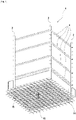
- the figure 1 represents, in perspective, a self-supporting structure 1, or else a portion of self-supporting structure 1, according to a first embodiment of the present invention.
- the self-supporting structure 1 is intended to be installed prior to the casting of the concrete of a wall, for example shuttered or cast in situ, and to be embedded inside the concrete wall.
- the purpose of the self-supporting structure is thus to allow the positioning and maintenance of various equipment and accessories that must be present in the shuttered wall, prior to the pouring of the concrete.
- the self-supporting structure 1 is provided to form a fixed rigid structure which can be used as a support for the various accessories or equipment.
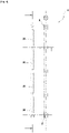
- the self-supporting structure has the general shape of a vertical grid, bent, formed by at least two uprights 2 vertical or substantially vertical (see picture 3 ), interconnected by at least one transverse element 4 (see figure 4 ).
- the self-supporting structure 1 is not intended to have a function in the shuttered wall, once it has been produced and finished, but is intended to facilitate its manufacture.
- the self-supporting structure of the first embodiment is distinct from the frame of the shuttered wall.
- the self-supporting structure 1 comprises three uprights 2, arranged so as to form a right-angled triangle between them, and connected by four transverse elements 4.
- the uprights 2 may comprise transverse slots 6, for example with a rectangular or square outline, intended to accommodate the ends of the transverse elements 4.
- the transverse elements 4 for example at rectangular or square cross section to allow rotational connection with the uprights 2, may have ends configured to cooperate with the openings 6 of the uprights 2.
- the transverse elements 4 may have, at each end, a notch 8 intended to cooperate with an edge of the slot 6 when the transverse element 4 is mounted on the upright 2, so as to secure the transverse element 4 to the upright 2 and avoid its involuntary removal from the slot 6.
- the uprights 2 may also include circular transverse openings 10, for mounting other transverse elements, such as rods, or else for mounting equipment or accessories directly on the uprights 2.
- the uprights 2 can also include openings of specific shape for a very particular piece of equipment.
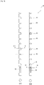
- the uprights 2 may comprise, in the lower part, on the side of their lower end, an oblong opening 12, preferably with retaining lugs, to allow a sealing strip 14 to be installed there (see picture 2 ).
- a sealing strip 14 makes it possible in particular to guarantee sealing at the interface between a concrete floor slab 15, or horizontal concrete platform 15 or slab 15, and the shuttered wall. Thanks to the self-supporting structure, it is possible to correctly position and maintain in position throughout the construction site said sealing strip 14, until it is completely embedded in the concrete of the slab 15 and the shuttered wall .
- the self-supporting structure 1 described is intended to allow the construction of a vertical shuttered wall.
- the self-supporting structure 1 is arranged vertically on its support.
- the amounts 2 can be fixed on a solid support, for example a concrete slab.
- fixing means such as screws, can be provided at the level of the feet of the uprights 2 to guarantee their mounting on the concrete slab.
- the feet of the uprights can also be provided to be embedded in the concrete slab 15 (see figure 2 ).
- the uprights 2 can rest on the support of the concrete slab 15, before the latter is cast.
- the feet of the uprights 2 can rest on steel reinforcements 16 of the concrete slab, for example with abutment means configured to rest on one or more rods of the reinforcement 16: in this case, the feet of the uprights 2 will remain correctly positioned relative to the reinforcements 16 of the concrete slab, even when the concrete of the slab is poured.
- the uprights 2 are then fixed and immobilized in the concrete slab 15, without requiring any specific additional fixing step, thus allowing the easy mounting of the accessories and equipment of the shuttered wall on the self-supporting structure 1.
- the steel reinforcements 18 of the shuttered wall can be positioned on the self-supporting structure 1, for example using side hooks, and extend as far as the steel reinforcement 16 of the concrete slab 15.
- the lower part of the vertical reinforcements 18 will be embedded in the concrete of the slab, at the same time as the feet of the uprights 2 of the self-supporting structure 1.
- specific steel reinforcements with an upper end curved in an inverted U can be mounted on the transverse elements 4 and extend up to the reinforcement 16 of the slab, with a view to being embedded both by the concrete of the slab then by the concrete of the shuttered wall.
- the transverse elements 4 can thus comprise longitudinal openings 20 on one of the transverse faces, for example on the upper face or on a side face.
- the longitudinal openings 20 can in particular allow the upper end of steel reinforcement elements having an inverted U-shaped end to be attached thereto.
- the transverse elements 4 may also include transverse openings (not shown) on the side faces, for mounting spacers for positioning and fixing the formwork elements.
- spacers make it possible to position the formwork elements correctly in space, but also with respect to the self-supporting structure, and to the equipment fixed to it. This makes it easier to keep the formwork elements in position and to dismantle them when the concrete of the shuttered wall has dried, by limiting the defects on the shuttered wall.
- spacers can be positioned in staggered rows: this gives blind holes in the final wall, and not through holes, which improves the sealing of the wall.
- the self-supporting structure 1 thus mounted on the concrete slab 15, it then becomes possible to hang equipment to equip the shuttered wall, such as sheaths for the installation of electric cables or fluid delivery pipes. It is also possible to fix there frames delimiting the future openings of the shuttered wall, such as windows or doors, or even additional vertical reinforcements, in addition to those 18 already engaged with the concrete slab.
- the equipment is positioned at a distance from each other, in order to improve the sealing of the final wall thanks to a minimum thickness of concrete between them.
- the formwork elements for pouring concrete can also be mounted on the self-supporting structure, in particular on the transverse elements 4, via spacers. This gives the internal structure of the shuttered wall with the formwork elements mounted on it. It then suffices to pour the concrete between the formwork elements to embed the internal structure, with the self-supporting structure 1 and the equipment, in the concrete and obtain the shuttered wall with the desired equipment.
- the self-supporting structure described above is intended to be completely embedded in the final shuttered wall.
- the self-supporting structure is not necessarily completely embedded in the shuttered wall, but can on the contrary protrude from the shuttered wall, in the upper part. This is particularly the case when it is desired to install another self-supporting structure above the shuttered wall made: it is then possible to mount the new self-supporting structure, and in particular its uprights, on the upper ends of the uprights of the self-supporting structure partially embedded in the shuttered wall.
- the self-supporting structure completely embedded in the shuttered wall, but with equipment embedded only in the lower part, for example reinforcing rods embedded in the lower part but protruding from the top of the shuttered wall, in order to allow a mechanical connection with a wall or an upper slab.
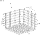
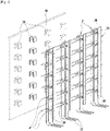
- the figure 5 represents, in perspective, a self-supporting structure 1', or else a portion of self-supporting structure 1', according to a second embodiment of the present invention.
- the self-supporting structure 1' is intended to be installed prior to the casting of the concrete of a wall, for example shuttered or cast in situ, and to be embedded inside the concrete wall.
- the self-supporting structure is thus intended to allow the positioning and maintenance of various equipment and accessories to be present in the shuttered wall, prior to the pouring of concrete, in particular formwork elements.
- the self-supporting structure 1' is provided to form a fixed rigid structure which can be used as a support for the various accessories or equipment.
- the self-supporting structure has the general shape of a vertical grid, bent, formed by at least two uprights 2′ vertical or substantially vertical, interconnected by at least a transverse element 4'.
- the self-supporting structure 1' constitutes all or part of the frame of the shuttered wall.
- the self-supporting structure 1' is formed, at least in part, of reinforcing bars, or reinforcing bars, so as to participate in the mechanical reinforcement of the concrete, in the same way as a standard reinforcement.
- the self-supporting structure 1' therefore makes it possible on the one hand to facilitate the manufacture of the shuttered wall, and on the other hand to participate in its mechanical properties, in particular in traction.
- the reinforcement of the shuttered wall may not be limited to the self-supporting structure 1', and additional reinforcing bars may be provided in addition to the self-supporting structure 1'. In the latter case, the reinforcement bars can in particular be positioned and fixed directly to the self-supporting structure 1'.
- the self-supporting structure 1' according to the second embodiment comprises eight uprights 2', arranged so as to form a right-angled triangle between them, and connected by twenty-four transverse elements 4'.
- the uprights 2' can be formed by two reinforcement bars 22 curved in an inverted U at their upper end and arranged vertically.
- the reinforcing bars 22 can in particular be held together, for example by strapping 24, in the example shown steel squares, distributed along the upright 2' and to which the reinforcing bars 22 are welded.
- strapping 24 allows the upright 2' to keep the same cross-section over its entire height, and to retain its geometry, even under stress, for example when pouring concrete.
- strapping 24 also constitutes attachment or attachment points for accessories, equipment or even reinforcing bars as will be described below.
- the strappings 24 can first of all comprise a peripheral contour that is longer than that of the upright 2'.
- the strappings 24 can have a depth that is longer than the upright 2': in other words, the reinforcing bars 22 can be welded at the level of the lateral sides of the strappings 24 and not at the level of the corners of the strappings 24.
- the strappings 24 therefore extend, in one direction, beyond the upright 2', and can thus form bearing edges for accessories, equipment or reinforcing bars.
- horizontal reinforcing bars 4' are arranged on the flanges formed by the strappings 24 of the uprights 2'.
- strappings 24 may also comprise, on one or more of their sides, one or more tapped holes or welded nuts 25.
- Such tapped holes or welded nuts 25 allow fixing, in particular reversible by screwing, of accessories or equipment , including formwork elements, directly on the self-supporting structure 1 '.
- retaining wedges 26 are screwed vertically onto the strappings 24 of the uprights 2', in order to allow formwork panels (not shown) to slide between them. Thanks to the parallel and regularly spaced uprights 2', the wedges 26 mounted on the uprights 2' are also correctly positioned and oriented to allow the subsequent insertion of the formwork panels.
- the wedges 26 can be mounted on the uprights 2' via spacers, for example in the form of tubes 28 placed between the tapped hole or welded nut 25 strapping 24 and wedges 26, and in which pass the fixing screws.
- spacers for example in the form of tubes 28 placed between the tapped hole or welded nut 25 strapping 24 and wedges 26, and in which pass the fixing screws.
- the figure 7 illustrates a formwork wall 30 intended to be mounted on the self-supporting structure 1 'and comprising inverted U-shaped connectors 32 arranged along the formwork wall 30.
- the connectors 32 are in particular configured to come to cooperate with the strappings 24 coming land on the upper rim on one side of the hoops 24.
- the formwork wall 30 is therefore held in engagement on the hoops 24 of the uprights 2' under the effect of its own weight.
- the connectors 32 will retain the formwork wall 30 at a distance from the uprights 2', despite the pressure exerted by the poured concrete on the formwork wall 30.
- the formwork wall 30 can be intended to remain in place.
- the self-supporting structure 1′ described is intended to allow the production of a vertical shuttered wall.
- the self-supporting structure 1' is arranged vertically on its support.
- the uprights 2' can be fixed to a solid support, for example a concrete slab.
- fastening means such as insertion holes, can be provided in the concrete slab to allow the insertion and then the sealing of the feet of the uprights 2'.
- the feet of the 2' uprights can also be designed to be embedded in the 15' concrete slab (see figure 6 ).
- the reinforcing bars 22 of the uprights 2' can be bent in L at their lower end, so as to be able to rest on the support of the concrete slab 15', before the latter is cast.
- the feet of the uprights 2' can be connected or fixed to steel reinforcements 16' of the concrete slab 15': in this case, the feet of the uprights 2' will remain correctly positioned with respect to the reinforcements 16' of the concrete slab, even when the concrete of the slab will be poured.
- the uprights 2' are then fixed and immobilized in the concrete slab 15', without requiring any specific additional fixing step, thus allowing the easy assembly of the accessories and equipment of the shuttered wall on the self-supporting structure 1', while having continuity of reinforcement between the slab and the future shuttered wall.
- the self-supporting structure 1′ thus mounted on the concrete slab 15′, it then becomes possible to hang thereon equipment to equip the shuttered wall, such as sheaths for the installation of electric cables or fluid conveying pipes. It is also possible to fix therein frames delimiting the future openings of the shuttered wall, such as windows or doors, or even additional vertical or horizontal reinforcements, in addition to those of the self-supporting structure 1'.
- the equipment is positioned at a distance from each other, in order to improve the sealing of the final wall thanks to a minimum thickness of concrete between them.
- the formwork elements for pouring the concrete can also be mounted on the self-supporting structure, in particular on the uprights 2′, via spacers 28 or connectors 32.
- the internal structure of the shuttered wall is thus obtained with the elements formwork mounted on it. It then suffices to pour the concrete between the formwork elements to embed the internal structure, with the self-supporting structure 1′ and the equipment, in the concrete and obtain the shuttered wall with the desired equipment.
- Such spacers or connectors 32 make it possible to correctly position the formwork elements in space, but also with respect to the self-supporting structure, and to the equipment fixed to it.
- the spacers/connectors can be positioned in staggered rows: this gives blind holes in the final wall, and not through holes, which improves the tightness of the wall.
- the self-supporting structure described above is intended to be completely embedded in the final shuttered wall.
- the self-supporting structure is not necessarily completely embedded in the shuttered wall, but can on the contrary protrude from the shuttered wall, in the upper part. This is particularly the case when it is desired to install another self-supporting structure above the shuttered wall made: it is then possible to mount the new self-supporting structure, and in particular its uprights, on the upper ends of the uprights of the self-supporting structure partially embedded in the shuttered wall.
- the self-supporting structure completely embedded in the shuttered wall, but with equipment embedded only in the lower part, for example reinforcing rods embedded in the lower part but protruding from the top of the shuttered wall, in order to allow a mechanical connection with a wall or an upper slab.
- the self-supporting structure according to the present invention, it becomes easy and reliable to position and maintain in position equipment and/or accessories for the construction of a wall, in particular shuttered. In particular, it becomes easy to visualize the wall to be made, and to position the different elements to equip it accordingly.
- the self-supporting structure also makes it possible to guarantee that the various elements thus fixed to it will be held in position during the pouring of the concrete, and will therefore be correctly placed inside the concrete of the wall once the concrete has dried.
Landscapes
- Engineering & Computer Science (AREA)
- Architecture (AREA)
- Civil Engineering (AREA)
- Structural Engineering (AREA)
- Panels For Use In Building Construction (AREA)
- Forms Removed On Construction Sites Or Auxiliary Members Thereof (AREA)
- Finishing Walls (AREA)
Applications Claiming Priority (1)
| Application Number | Priority Date | Filing Date | Title |
|---|---|---|---|
| FR2103675A FR3121694B1 (fr) | 2021-04-09 | 2021-04-09 | Structure autoportante, et mur en béton comprenant une telle structure autoportante |
Publications (2)
| Publication Number | Publication Date |
|---|---|
| EP4071320A2 true EP4071320A2 (de) | 2022-10-12 |
| EP4071320A3 EP4071320A3 (de) | 2022-12-28 |
Family
ID=75954090
Family Applications (1)
| Application Number | Title | Priority Date | Filing Date |
|---|---|---|---|
| EP22167496.3A Withdrawn EP4071320A3 (de) | 2021-04-09 | 2022-04-08 | Selbsttragende struktur und betonwand mit einer solchen selbsttragenden struktur |
Country Status (2)
| Country | Link |
|---|---|
| EP (1) | EP4071320A3 (de) |
| FR (1) | FR3121694B1 (de) |
Family Cites Families (2)
| Publication number | Priority date | Publication date | Assignee | Title |
|---|---|---|---|---|
| GB2203477B (en) * | 1987-04-13 | 1991-05-15 | Gary Kenneth Busch | Concrete building construction |
| KR100189216B1 (ko) * | 1996-11-14 | 1999-06-01 | 소광민 | 조립식 철골조와 이를 이용한 건축공법 |
-
2021
- 2021-04-09 FR FR2103675A patent/FR3121694B1/fr not_active Expired - Fee Related
-
2022
- 2022-04-08 EP EP22167496.3A patent/EP4071320A3/de not_active Withdrawn
Also Published As
| Publication number | Publication date |
|---|---|
| FR3121694A1 (fr) | 2022-10-14 |
| FR3121694B1 (fr) | 2024-03-15 |
| EP4071320A3 (de) | 2022-12-28 |
Similar Documents
| Publication | Publication Date | Title |
|---|---|---|
| EP2402531A2 (de) | Vorgefertige Betontreppe mit modularer Treppenwange | |
| FR2547848A1 (fr) | Paroi prefabriquee destinee a la construction de maisons et autres batiments, et son procede de fabrication | |
| EP4071320A2 (de) | Selbsttragende struktur und betonwand mit einer solchen selbsttragenden struktur | |
| FR2743588A1 (fr) | Systeme de gros oeuvre pour la construction de batiments notamment des maisons individuelles | |
| EP3070221B1 (de) | Verfahren zur behandlung von wärmebrücken, entsprechendes wärmeisolationselement und entsprechendes strukturelles verbindungselement sowie mit diesen elementen ausgerüstete schal-betonplatte | |
| CH628382A5 (en) | Construction element for the erection of walls, particularly retaining walls | |
| FR2745838A1 (fr) | Dispositif de fixation pour un montage de forme de plancher | |
| FR2973407A1 (fr) | Plaque mince en beton fibre comportant des moyens de liaison avec une piece en beton, et element de construction comportant une telle plaque mince | |
| FR3118979A1 (fr) | Panneau de construction et procédé de fabrication d’un mur au moyen d’un tel panneau | |
| EP2148019A2 (de) | Blockbaustein für Mauern | |
| FR3030590A1 (fr) | Systeme et procede de construction d'un mur a entretoise | |
| CH712909B1 (fr) | Dispositif de mise en attente d'armatures de liaison entre deux parties d'un ouvrage en béton et procédé de fabrication de ce dispositif. | |
| FR3026121A1 (fr) | Batiment a isolation thermique amelioree, procede de construction dudit batiment et agrafes concues pour la mise en oeuvre dudit procede | |
| FR2943701A1 (fr) | Procede de fabrication d'un panneau prefabrique destine a former une paroi isolante de batiment | |
| EP0784128B1 (de) | Verfahren zur Herstellung eines Paneels mit tragender Holzkonstruktion, durch das Verfahren hergestelltes Paneel, und mindestens ein derartiges Paneel enthaltendes Bauwerk | |
| FR2516584A1 (fr) | Dispositif pour construire l'encadrement d'une fenetre ou analogue dans l'industrie du batiment | |
| FR2985753A1 (fr) | Coffrage de baie de fenetre. | |
| FR2938856A1 (fr) | Chapiteau prefabrique en beton, et procede de mise en oeuvre d'un tel chapiteau dans une ossature de plancher | |
| BE1031238B1 (fr) | Voile préfabriqué en béton armé destiné à être utilisé dans un coffrage pour construire un mur en béton | |
| FR3036419A1 (fr) | Poutrelle de ferraillage pour coffrage de mur de piscine | |
| FR3022271A1 (fr) | Construction mixte bois et beton | |
| FR2908144A1 (fr) | Dispositif de support de coffrage pour ouvrages tels des bassins en beton | |
| FR2912440A1 (fr) | Panneau prefabrique destine a former une paroi isolante d'un batiment,et procede de fabrication de ce panneau | |
| FR3039185A1 (fr) | Module de construction pour piscine, piscine associee et procede de realisation d'une piscine | |
| FR2955602A1 (fr) | Procede pour realiser des ouvrages de genie civil, tel qu'une piscine ou un bassin de retenue d'eau |
Legal Events
| Date | Code | Title | Description |
|---|---|---|---|
| PUAI | Public reference made under article 153(3) epc to a published international application that has entered the european phase |
Free format text: ORIGINAL CODE: 0009012 |
|
| STAA | Information on the status of an ep patent application or granted ep patent |
Free format text: STATUS: THE APPLICATION HAS BEEN PUBLISHED |
|
| AK | Designated contracting states |
Kind code of ref document: A2 Designated state(s): AL AT BE BG CH CY CZ DE DK EE ES FI FR GB GR HR HU IE IS IT LI LT LU LV MC MK MT NL NO PL PT RO RS SE SI SK SM TR |
|
| PUAL | Search report despatched |
Free format text: ORIGINAL CODE: 0009013 |
|
| AK | Designated contracting states |
Kind code of ref document: A3 Designated state(s): AL AT BE BG CH CY CZ DE DK EE ES FI FR GB GR HR HU IE IS IT LI LT LU LV MC MK MT NL NO PL PT RO RS SE SI SK SM TR |
|
| RIC1 | Information provided on ipc code assigned before grant |
Ipc: E04B 1/16 20060101ALN20221124BHEP Ipc: E04C 5/06 20060101ALI20221124BHEP Ipc: E04G 21/18 20060101AFI20221124BHEP |
|
| STAA | Information on the status of an ep patent application or granted ep patent |
Free format text: STATUS: THE APPLICATION IS DEEMED TO BE WITHDRAWN |
|
| 18D | Application deemed to be withdrawn |
Effective date: 20230629 |