EP4071095B1 - Vorrichtung und verfahren zur messung von parametern von bahnmaterialstämmen - Google Patents
Vorrichtung und verfahren zur messung von parametern von bahnmaterialstämmen Download PDFInfo
- Publication number
- EP4071095B1 EP4071095B1 EP22166433.7A EP22166433A EP4071095B1 EP 4071095 B1 EP4071095 B1 EP 4071095B1 EP 22166433 A EP22166433 A EP 22166433A EP 4071095 B1 EP4071095 B1 EP 4071095B1
- Authority
- EP
- European Patent Office
- Prior art keywords
- log
- pick
- logs
- feed path
- measuring
- Prior art date
- Legal status (The legal status is an assumption and is not a legal conclusion. Google has not performed a legal analysis and makes no representation as to the accuracy of the status listed.)
- Active
Links
Images









Classifications
-
- B—PERFORMING OPERATIONS; TRANSPORTING
- B65—CONVEYING; PACKING; STORING; HANDLING THIN OR FILAMENTARY MATERIAL
- B65H—HANDLING THIN OR FILAMENTARY MATERIAL, e.g. SHEETS, WEBS, CABLES
- B65H18/00—Winding webs
- B65H18/28—Wound package of webs
-
- G—PHYSICS
- G01—MEASURING; TESTING
- G01N—INVESTIGATING OR ANALYSING MATERIALS BY DETERMINING THEIR CHEMICAL OR PHYSICAL PROPERTIES
- G01N3/00—Investigating strength properties of solid materials by application of mechanical stress
- G01N3/08—Investigating strength properties of solid materials by application of mechanical stress by applying steady tensile or compressive forces
-
- B—PERFORMING OPERATIONS; TRANSPORTING
- B65—CONVEYING; PACKING; STORING; HANDLING THIN OR FILAMENTARY MATERIAL
- B65H—HANDLING THIN OR FILAMENTARY MATERIAL, e.g. SHEETS, WEBS, CABLES
- B65H19/00—Changing the web roll
- B65H19/22—Changing the web roll in winding mechanisms or in connection with winding operations
- B65H19/30—Lifting, transporting, or removing the web roll; Inserting core
-
- B—PERFORMING OPERATIONS; TRANSPORTING
- B65—CONVEYING; PACKING; STORING; HANDLING THIN OR FILAMENTARY MATERIAL
- B65H—HANDLING THIN OR FILAMENTARY MATERIAL, e.g. SHEETS, WEBS, CABLES
- B65H26/00—Warning or safety devices, e.g. automatic fault detectors, stop-motions, for web-advancing mechanisms
-
- G—PHYSICS
- G01—MEASURING; TESTING
- G01G—WEIGHING
- G01G17/00—Apparatus for or methods of weighing material of special form or property
- G01G17/02—Apparatus for or methods of weighing material of special form or property for weighing material of filamentary or sheet form
-
- G—PHYSICS
- G01—MEASURING; TESTING
- G01N—INVESTIGATING OR ANALYSING MATERIALS BY DETERMINING THEIR CHEMICAL OR PHYSICAL PROPERTIES
- G01N33/00—Investigating or analysing materials by specific methods not covered by groups G01N1/00 - G01N31/00
- G01N33/34—Paper
-
- B—PERFORMING OPERATIONS; TRANSPORTING
- B25—HAND TOOLS; PORTABLE POWER-DRIVEN TOOLS; MANIPULATORS
- B25J—MANIPULATORS; CHAMBERS PROVIDED WITH MANIPULATION DEVICES
- B25J15/00—Gripping heads and other end effectors
- B25J15/0028—Gripping heads and other end effectors with movable, e.g. pivoting gripping jaw surfaces
-
- B—PERFORMING OPERATIONS; TRANSPORTING
- B65—CONVEYING; PACKING; STORING; HANDLING THIN OR FILAMENTARY MATERIAL
- B65H—HANDLING THIN OR FILAMENTARY MATERIAL, e.g. SHEETS, WEBS, CABLES
- B65H2301/00—Handling processes for sheets or webs
- B65H2301/40—Type of handling process
- B65H2301/41—Winding, unwinding
- B65H2301/414—Winding
- B65H2301/4144—Finishing winding process
- B65H2301/41445—Finishing winding process after winding process
-
- B—PERFORMING OPERATIONS; TRANSPORTING
- B65—CONVEYING; PACKING; STORING; HANDLING THIN OR FILAMENTARY MATERIAL
- B65H—HANDLING THIN OR FILAMENTARY MATERIAL, e.g. SHEETS, WEBS, CABLES
- B65H2301/00—Handling processes for sheets or webs
- B65H2301/40—Type of handling process
- B65H2301/44—Moving, forwarding, guiding material
- B65H2301/448—Diverting
-
- B—PERFORMING OPERATIONS; TRANSPORTING
- B65—CONVEYING; PACKING; STORING; HANDLING THIN OR FILAMENTARY MATERIAL
- B65H—HANDLING THIN OR FILAMENTARY MATERIAL, e.g. SHEETS, WEBS, CABLES
- B65H2301/00—Handling processes for sheets or webs
- B65H2301/50—Auxiliary process performed during handling process
- B65H2301/54—Auxiliary process performed during handling process for managing processing of handled material
- B65H2301/542—Quality control
- B65H2301/5421—Quality control taking samples
-
- B—PERFORMING OPERATIONS; TRANSPORTING
- B65—CONVEYING; PACKING; STORING; HANDLING THIN OR FILAMENTARY MATERIAL
- B65H—HANDLING THIN OR FILAMENTARY MATERIAL, e.g. SHEETS, WEBS, CABLES
- B65H2511/00—Dimensions; Position; Numbers; Identification; Occurrences
- B65H2511/10—Size; Dimensions
- B65H2511/14—Diameter, e.g. of roll or package
-
- B—PERFORMING OPERATIONS; TRANSPORTING
- B65—CONVEYING; PACKING; STORING; HANDLING THIN OR FILAMENTARY MATERIAL
- B65H—HANDLING THIN OR FILAMENTARY MATERIAL, e.g. SHEETS, WEBS, CABLES
- B65H2515/00—Physical entities not provided for in groups B65H2511/00 or B65H2513/00
- B65H2515/10—Mass, e.g. mass flow rate; Weight; Inertia
-
- B—PERFORMING OPERATIONS; TRANSPORTING
- B65—CONVEYING; PACKING; STORING; HANDLING THIN OR FILAMENTARY MATERIAL
- B65H—HANDLING THIN OR FILAMENTARY MATERIAL, e.g. SHEETS, WEBS, CABLES
- B65H2515/00—Physical entities not provided for in groups B65H2511/00 or B65H2513/00
- B65H2515/12—Density
-
- B—PERFORMING OPERATIONS; TRANSPORTING
- B65—CONVEYING; PACKING; STORING; HANDLING THIN OR FILAMENTARY MATERIAL
- B65H—HANDLING THIN OR FILAMENTARY MATERIAL, e.g. SHEETS, WEBS, CABLES
- B65H2515/00—Physical entities not provided for in groups B65H2511/00 or B65H2513/00
- B65H2515/84—Quality; Condition, e.g. degree of wear
-
- B—PERFORMING OPERATIONS; TRANSPORTING
- B65—CONVEYING; PACKING; STORING; HANDLING THIN OR FILAMENTARY MATERIAL
- B65H—HANDLING THIN OR FILAMENTARY MATERIAL, e.g. SHEETS, WEBS, CABLES
- B65H2701/00—Handled material; Storage means
- B65H2701/10—Handled articles or webs
- B65H2701/19—Specific article or web
- B65H2701/1924—Napkins or tissues, e.g. dressings, toweling, serviettes, kitchen paper and compresses
-
- G—PHYSICS
- G01—MEASURING; TESTING
- G01B—MEASURING LENGTH, THICKNESS OR SIMILAR LINEAR DIMENSIONS; MEASURING ANGLES; MEASURING AREAS; MEASURING IRREGULARITIES OF SURFACES OR CONTOURS
- G01B11/00—Measuring arrangements characterised by the use of optical techniques
- G01B11/08—Measuring arrangements characterised by the use of optical techniques for measuring diameters
-
- G—PHYSICS
- G01—MEASURING; TESTING
- G01N—INVESTIGATING OR ANALYSING MATERIALS BY DETERMINING THEIR CHEMICAL OR PHYSICAL PROPERTIES
- G01N2203/00—Investigating strength properties of solid materials by application of mechanical stress
- G01N2203/02—Details not specific for a particular testing method
- G01N2203/026—Specifications of the specimen
- G01N2203/0262—Shape of the specimen
- G01N2203/0278—Thin specimens
- G01N2203/0282—Two dimensional, e.g. tapes, webs, sheets, strips, disks or membranes
Definitions
- the present invention relates to improvements to devices and methods for measuring one or more characteristic, i.e., parameters or sizes of a log of web material, for example but not exclusively logs of tissue paper, useful for controlling the production process.
- weight is important in the field of tissue paper, used to produce rolls of toilet tissue, kitchen towels and similar articles.
- a further parameter, i.e., characteristic, which in some cases is useful for controlling the production process is firmness.
- the diameter of the logs can also be important for controlling production.
- the measurements of at least some of these parameters takes place in a laboratory, on samples of logs picked up from the production line. This measuring method is not satisfactory, as the measurement obtained outside the line does not allow real time correction of the production parameters in order to correct any divergences of the firmness measured relative to the values desired.
- each log produced is fed along a feed path with a movement parallel to the axis of the log.
- a device for firmness measuring provided with a wheel positioned at a distance with respect to a surface on which the log is supported, so as to apply a known compressive force to the log, when the log passes between the wheel and the supporting surface.
- the thrust exerted by the log on the wheel causes lifting of the wheel.
- the displacement of the wheel is a function of the diameter of the log and of the compressive deformation (compression) of the log caused by the force applied by the wheel.
- This system is particularly complex and requires the logs to be fed in the direction of their axis. This condition is incompatible with the configuration of the majority of production lines for logs of tissue paper, where the logs produced by a rewinder are fed along the feed path by rolling and hence orthogonally to their axis.
- the measuring system disclosed in EP1530044 is not particularly precise.
- any compression deformations of the tubular winding core on which the log is formed are erroneously added to the compression of the wound material.
- the more deformable the tubular winding core the greater this measurement defect will be.
- increasingly thin winding cores are produced, making them increasingly deformable by compression and tending to make the firmness measurement imprecise.
- a device for measuring parameters of a log of wound web material including a feed path for the logs, configured to feed the logs in a direction orthogonal to the axis of the logs, and one or more pick-up members, for example two pick-up members spaced from one another in a direction transverse to the feed path of the logs.
- the pick-up member or members is/are adapted to pick up individual logs from a pick-up position along the feed path and to transfer each log from the measuring position back to the feed path.
- the number of pick-up members can depend on the length of the logs to be handled. For short logs, i.e., with a limited longitudinal dimension, a single pick-up member may suffice. For longer logs, a pair of pick-up members may be required, or even more than two pick-up members aligned with one another in a direction transverse to the direction of movement of the logs along the feed path.
- the device can be controlled to randomly pick up logs, and to measure one or more parameters of these logs.
- the device can be configured to measure only the weight of the log. In other embodiments the device can be configured to measure only the firmness of the log.
- the device can be configured to measure both the firmness and the weight of the log.
- the device can also measure the diameter of the log, or can be combined with a different device that measures the diameter of the log, even in a position distanced from the point in which the device is located.
- the device has many advantages with respect to known devices, including its simplicity and limited footprint, while maintaining high measurement precision and flexibility.
- the device thus configured can be inserted in existing converting lines, i.e., lines for producing logs from reels of large diameter, for instance, substantially without requiring to modify the layout thereof, or with minor modifications. This is facilitated by the small footprint of the device, which can be inserted into existing spaces along a previously installed line.
- the pick-up member(s) is(are) adapted to measure at least one parameter of the picked-up log, while the log is engaged with the pick-up member(s).
- each pick-up member can comprise a respective weight sensor, for example a load cell, which allows the weight of the log picked up by the pick-up members to be measured, while the log is still engaged with said pick-up member(s). This allows fast measurements to be obtained with a very compact structure of the device.
- the pick-up member(s) is(are) adapted to transfer each log picked up from the measuring position back to the pick-up position along the feed path of the logs.
- the logs are picked up from the feed path in one point and re-inserted into the feed path in the same point in which they were picked up. This contributes to the simplicity and compactness of the device.
- each pick-up member comprises a gripper with a first jaw and a second jaw, the first jaw being located upstream of the second jaw with respect to the direction of feed of the logs along the feed path.
- the first jaw and the second jaw pivot about respective pivot axes orthogonal to the direction of feed of the logs along the feed path and parallel to the axes of the logs and their movement can advantageously be controlled by a first actuator for controlling the movement of the first jaw and by a second actuator for controlling the movement of the second jaw.
- the first and the second actuator can be independent and controlled in a manner coordinated with respect to each other, to perform suitable maneuvers with the jaws of the grippers.
- this allows operations to pick up and release the individual logs in the flow of the logs along the feed path, without interfering with or obstructing the normal feed of the logs.
- Feed of the logs along the path can take place by rolling under the effect of gravity, the path being defined by an inclined chute, for instance.
- the device can comprise only one or more pick-up members, with which sensors, for example load cells for measuring weight, are associated.
- the measuring device can have a measuring system of the log firmness.
- This system can comprise a pair of blocking heads, adapted to block a log by means of tailstocks, located above the feed path and at the sides of the feed path.
- At least one of the blocking heads, and preferably each blocking head comprises a log firmness measuring member.
- the blocking heads are aligned transverse to the feed path along a direction orthogonal to the direction of feed of the logs along the feed path and parallel to the direction of the axes of the logs along the feed path.
- the pick-up member(s) is(are) adapted to position each picked-up log in a measuring position, in which the log interacts with the blocking heads and with the log firmness measuring member, associated with the blocking head.
- Each log firmness measuring member can, for example, comprise a presser adapted to apply a predetermined load against the surface of a log picked up from the feed path and a measuring arrangement of the degree of penetration of the presser in the log as a result of a predetermined load applied by the presser.
- a method for manufacturing logs of web material comprising the following steps:
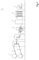
- Fig. 1 schematically shows a side view of a portion of a converting line 1 for producing logs R of tissue paper.
- the converting line 1 comprises a rewinder 7, that winds one or more plies of tissue paper V1, V2 coming from an unwinder 3 and unloads them into a feed path P that passes through a tail sealer 8.
- the tail or outer edge of the wound web material in each log R is sealed to the outer surface of the log by the tail sealer 8.
- a measuring station located in which is a measuring device 9 that measures one or more parameters of logs R picked up randomly from the feed path P of the logs along the converting line 1.
- a storage unit 11 Arranged downstream of the measuring station, there can be one or more further stations of the converting line, for example a storage unit 11 and a log saw 12 that cuts each log into rolls of smaller axial dimensions, which are then packaged in a packaging section (not shown) of the converting line 1.
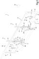
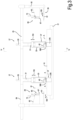
- the measuring device 9 and its operating cycle will be described in detail hereunder, with specific reference to Figs.2 to 9 .
- the letter P indicates the feed path of the logs R, which in the device 9 is defined by a chute 21 or other surface for supporting the logs.
- the feed path P is configured so as to allow feed by gravity; the logs R roll on the chute 21, which is inclined to facilitate feed of the logs R. Nonetheless, it would also be possible to provide a feed path in which the logs R are controlled and moved by feed members.
- the measuring device 9 comprises a stationary bearing structure, which has a cross member 25 extending transverse to the feed path P, and hence transverse to the direction of feed of the logs R along the feed path P, represented by the arrow P.
- One or more pick-up members 27 are mounted on the cross member 25. In the illustrated embodiment two pick-up members 27 are provided.
- the pick-up members 27 are substantially the same as one another. In other embodiments, the pick-up members 27 can be symmetrical with respect to a vertical plane, parallel to the feed path P of the logs R.
- the pick-up members 27 are spaced from one another along the cross member 25, so as to engage the logs R, on which the measurements are carried out.
- the pick-up members 27 are located in two positions fixed with respect to the transverse direction (orthogonal to P), but it would also be possible to mount the pick-up members 27 so that their mutual distance and/or their position with respect to the direction transverse to the feed path P is adjustable, for example as a function of the axial length of the logs R.
- the measuring device 9 further comprises two blocking heads 29, substantially symmetrical to each other with respect to a plane orthogonal to the cross member 25 and located on opposite sides of the feed path P.
- the two blocking heads 29 are located externally to the pick-up members 27 and are movable according to the double arrows f29 parallel to the cross member 25 to move toward and away from each other.
- Each pick-up member 27 is movable along a respective vertical upright 31, integral with the cross member 25.
- a load-bearing structure comprising a slide 33 of the pick-up member 27 slides along the upright 31 according to the double arrow f33. In Figs. 2 and 3 the two pick-up members 27 are shown in their lowest position.
- the lifting and lowering movement according to f33 of the slides 33 is controlled by respective linear actuators 35, for example piston-cylinder actuators.
- a gripper 37 comprising a first jaw 37A and a second jaw 37B, is constrained to each slide 33.
- the two jaws 37A, 37B are different from each other. More precisely, the first jaw 37A, which is located upstream of the second jaw 37B with respect to the direction of feed of the logs R along the feed path P, is shorter than the second jaw 37B.
- the second jaw 37B comprises, by way of example, a concave surface 37C against which the log R is pushed by the first jaw 37A, as will be described in greater detail below with reference to an operating cycle.
- Each of the two jaws 37A, 37B is controlled by its own actuator.
- a first actuator 39A controls the first jaw 37A and a second actuator 39B controls the second jaw 37B.
- the actuators 39A, 39B can be electronically controlled electric motors or other rotary actuators, which move the two jaws 37A, 37B about rotation axes A parallel to each other and parallel to the cross member 25.
- the use of two separate actuators 39A, 39B for the two jaws 37A, 37B of each gripper 37 allows the two jaws 37A, 37B to carry out rotation movements about the axes A that are staggered from each other, for reasons that will be apparent from the description of an operating cycle. Therefore, the actuators are independent but controlled so as to carry out coordinated movements with respect to each other.
- the jaws 37A, 37B and the actuators 39A, 39B are supported by the slide 33 by means of a support 40, which is constrained to the slide 33 with the interposition of a load cell 41.
- the load cell 41 of each gripper 37 can measure the weight of a log R engaged by the grippers 37 in the manner described hereunder.
- Each blocking head 29 has a structure described below with reference in particular to Figs. 2 , 3 and 5 .
- Each blocking head 29 comprises an upright 50 engaged with guides integral with the cross member 25, not shown, to move according to the double arrow f29 parallel to the cross member 25.
- the movement according to f29 is imparted to each measuring head 29 by an actuator, not shown, for example an electronically controlled electric motor.
- a tailstock 61 oriented parallel to the cross member 25, is fixed in the lower part of the upright 50 of each blocking head 29.
- the two tailstocks 61 of the two blocking heads 29 are oriented facing each other and are coaxial.
- An arm 63 which carries log firmness measuring members, indicated as a whole with 65, can be fixed on the upright 50 of the blocking head 29, above the respective tailstock 61.
- the firmness measuring members 65 comprise a presser 67 integral with a rod 67A integral with a slide 69, which slides in vertical direction according to the double arrow f69 along a guide 71 integral with the arm 63.
- the measuring member 65 can be provided on only one of the two blocking heads 29.
- a linear actuator 73 for example a piston-cylinder actuator, is connected to the slide 69 and controls the movement thereof according to the double arrow f69.
- a bracket 77 constrains the rod of the linear actuator 73 to the slide 69.
- a measuring arrangement i.e., a sensor 75, for example a laser sensor, measures the position of the slide 69 and hence of the presser 67 with respect to the arm 63 and with respect to the tailstock 61.
- the presser 67 is calibrated in diameter and weight and applies a known compression force on the log R that is positioned in the measuring device.
- the degree of penetration of the presser 67 into the wound web material of the log R is determined in order to detect the firmness, as described in greater detail below.
- a measuring system of the diameter of the logs R is also associated with the measuring device 9.
- this measuring system is represented as a laser emitter 81, which detects the passage of the logs and determines the diameter thereof.
- the measuring system 81 is positioned so as to measure the diameter of a log R when this is close to the grippers 37 of the pick-up members 27.
- the measuring cycle is as follows. Measurements are carried out randomly only on some logs R being fed along the feed path P through the measuring device 9.
- the logs can be chosen randomly, either by an operator, or in a programmed manner, for example one log every N logs produced, or in any other suitable way.
- Operation of the measuring device 9 is controlled by means of a control unit indicated schematically with 100 in Fig. 2 and that can be interfaced with a higher-level control unit, which manages the converting line 1.
- the control unit 100 can advantageously be interfaced with the sensors and the actuators described above, in particular with the actuators 39A, 39B, 35, 73 and with the sensors 41, 75, 81.
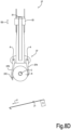
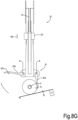
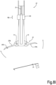
- Figs. 8A-8J illustrates in detail the operation of a pick-up member 27.
- the pick-up member 27 is in an idle position and is above the feed path P of the logs R, which can pass through the measuring device 9 without interacting therewith.
- Figs. 8B-8J show the pick-up sequence of a single log R from the feed path P, the transfer thereof to the blocking heads 29 and the release thereof into the feed path P ( Fig.8G ), substantially in the same position from which it was picked up ( Fig.8B ).
- the pick-up members 27 are lowered toward the chute 21 to a height such as to interact with the logs R.
- the second jaw 37B of the gripper 37 is rotated downward ( Fig.8B ), in order to stop the approaching log R.
- the first jaw 37A of the gripper 37 is lowered, closing the gripper 37 and engaging the log R in the gripper.
- the pick-up members 27 are lifted ( Fig.8D ) to take the log R out of the feed path of the logs P. More in particular, the log R is taken with its tubular winding core C in alignment with the tailstocks 61 of the blocking assembly 29, so that these, by moving toward each other (arrow f29), are inserted from opposite ends in the tubular winding core C.
- the grippers 37 open ( Fig.8E ) and release the log R on the tailstocks, so that the firmness of the log is measured, in the manner described below with reference to the sequence of Figs. 9A-9E .
- the grippers 37 close again ( Fig.8F ), the tailstocks 61 are extracted from the tubular core C and the grippers 37 are lowered to release the log R on the chute 21 in the feed path P.
- the log R continues rolling along the path, while the pick-up members 27 are lifted again ( Fig.8H ) and the jaws 37A, 37B open ( Fig.8I ) and finally the pick-up members 27 with the open grippers move toward the chute 21 ( Fig.8J ) in the position in which a new log R can be picked up, repeating the above described sequence.
- the logs R are picked up randomly, with a frequency that can be fixed or variable, automatically and/or manually controlled, so as to repeat with the most suitable frequency a random control on the parameters (diameter, weight and compactness) of the logs produced by the rewinder.
- the weight of the log R is measured by means of the load cells.
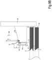
- Figs.9A -9H illustrates the operations carried out during the measuring cycle by the blocking heads 29 and by the measuring assembly 65.
- the operations illustrated in the sequence of Figs.9A -9H are coordinated with the operations carried out by the pick-up members 27 illustrated in Figs. 8A-8J .
- Fig. 9A the pick-up members 27 have carried the log R in alignment with the tailstocks 61.
- a laser sensor or other suitable means such as a video camera
- the position of the log R for correct insertion of the tailstocks 61 is detected.
- Centering between the tubular core C of the log R and the tailstocks 61 can take place with a lifting and lowering movement of the grippers 37 and with a synchronized rotation movement of the jaws 37A, 37B of each gripper 37 that causes a movement with a horizontal component of the log R.
- these can be controlled separately from one another, so as to be able to center the two ends of the tubular winding core C relative to the two tailstocks 61.
- the two blocking heads 29 can be moved toward each other so as to insert the tailstocks 61 in the tubular core C, see Fig.9B .
- the log R is still engaged by the jaws 37A, 37B of the grippers 37.
- the jaws 37A, 37B of the grippers 37 open and the log R is placed on the tailstocks 61, which come into contact with the inner surface of the tubular core C. In this position the log firmness can be measured.
- the linear actuator 73 lowers the presser 67.
- the actuator 73 comprises a rod 73A that engages in a hole of a plate 69A of the slide 69 ( Fig. 9D ), so that the actuator 73 can extend completely, while the presser 67 comes into contact with the outer surface of the log R and stops at a height that is determined by the extent to which the wound web material in the log R is compressed under the weight of the presser 67 alone.
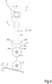
- Fig.9E schematically shows how the presser 67 penetrates the theoretical cylindrical surface of the log R compressing the turns of wound web material. The penetration depth is proportional to softness, and hence is a function of the firmness of the log R.
- the sensor 75 detects the position of the log R with respect to the position of the presser 67.
- the sensor detects the degree of penetration PI of the presser 67 based on the diameter of the log R, which was measured or will be measured by the sensor 81.
- the compression measured is determined solely from the variation of thickness of the material comprised between the presser 67 and the tailstock 61. Therefore, the firmness measurement obtained is not affected by errors, typical of prior art measuring systems, due to compression of the tubular winding core during measurement.
- the random measurement of the firmness of the log R can be used to take action on the production parameters of the converting line.
- the firmness of the log can be corrected, if the measurement is outside an admissible range, by acting on the tension of the web material in the rewinder and/or by acting on the embossing conditions of the plies forming the web material of the log, in a manner known per se by those skilled in the art.
Landscapes
- Physics & Mathematics (AREA)
- Life Sciences & Earth Sciences (AREA)
- Chemical & Material Sciences (AREA)
- General Physics & Mathematics (AREA)
- Health & Medical Sciences (AREA)
- General Health & Medical Sciences (AREA)
- Analytical Chemistry (AREA)
- Biochemistry (AREA)
- Immunology (AREA)
- Pathology (AREA)
- Medicinal Chemistry (AREA)
- Food Science & Technology (AREA)
- Engineering & Computer Science (AREA)
- Replacement Of Web Rolls (AREA)
- Processing And Handling Of Plastics And Other Materials For Molding In General (AREA)
Claims (26)
- Vorrichtung (9) zum Messen von Parametern einer Rolle (R) gewickelten Bahnmaterials mit:einem Förderweg (P) für die Rollen (R), der ausgebildet ist,um die Rollen in einer Richtung orthogonal zu der Achse der Rollen zu fördern,mindestens einem Aufnahmeelement (27), das ausgebildet ist um:- einzelne Rollen (R) von einer Aufnahmeposition entlang des Förderwegs (P) aufzunehmen,- jede Rolle (R) von der Messposition zurück zu dem Förderweg zu übertragen.
- Vorrichtung nach Anspruch 1 mit zwei Aufnahmeelementen (27), die von einander in einer Richtung quer zu dem Förderweg (P) der Rollen (R) beabstandet sind.
- Vorrichtung (9) nach Anspruch 1 oder 2, wobei mindestens ein Aufnahmeelement ausgebildet ist, um mindestens einen Parameter der aufgenommenen Rolle (R) zu messen, während die Rolle in Eingriff mit dem Aufnahmeelement (27) ist.
- Vorrichtung (9) nach Anspruch 1, 2 oder 3, wobei das mindestens eine Aufnahmeelement (27) ausgebildet ist, um jede Rolle (R), die aus der Messposition aufgenommen wurde, zurück zu der Aufnahmeposition entlang des Förderwegs der Rollen zu übertragen, wobei jedes Aufnahmeelement (27) einen Hub- und Senk-Aktuator (35) aufweist, der ausgebildet ist, um das Aufnahmeelement aus der Aufnahmeposition zu der Messposition und umgekehrt zu übertragen.
- Vorrichtung (9) nach einem oder mehreren der vorstehenden Ansprüche, wobei jedes Aufnahmeelement (27) ein Rollengewichts-Messelement (41) aufweist.
- Vorrichtung (9) nach einem oder mehreren der vorstehenden Ansprüche, wobei jedes Aufnahmeelement (27) einen Greifer (37) mit einer ersten Klemmbacke (37A) und einer zweiten Klemmbacke (37B) aufweist, wobei die erste Klemmbacke stromauf der zweiten Klemmbacke mit Bezug auf die Förderrichtung der Rollen (R) entlang des Förderwegs (PDE) angeordnet ist und wobei die erste Klemmbacke (37A )und die zweite Klemmbacke (37B) um jeweilige Schwenkachsen orthogonal zu der Förderrichtung der Rollen entlang des Förderwegs und parallel zu den Achsen der Rollen in dem Förderweg schwenken.
- Vorrichtung (9) nach Anspruch 6, wobei jeder Greifer (37) einen ersten Aktuator (39A) zum Steuern der Bewegung der ersten Klemmbacke (37A) und einen zweiten Aktuator (39B) zum Steuern der Bewegung der zweiten Klemmbacke (37B) aufweist.
- Vorrichtung (9) nach Anspruch 6 oder 7, wobei die zweite Klemmbacke (37B) länger als die erste Klemmbacke (37A) ist.
- Vorrichtung (9) nach Anspruch 6, 7 oder 8, wenn abhängig von Anspruch 5, wobei jedes Rollengewichts-Messelement (41) eine Lastzelle (41) aufweist und wobei die Lastzelle zwischen einem Träger (40), auf dem der jeweilige Greifer (37) montiert ist, und einer Lagerstruktur (33) angeordnet ist, die relativ zu dem Förderweg der Rollen bewegbar ist, um den Greifer (37) von der Aufnahmeposition in die Messposition und umgekehrt zu übertragen.
- Vorrichtung (9) nach einem oder mehreren der vorstehenden Ansprüche mit einem Paar von Sperrköpfen (29), die oberhalb des Förderwegs (P) und an den Seiten des Förderwegs angeordnet sind, wobei mindestens einer der Sperrköpfe (29) ein Rollen-Festigkeit-Messelement (65) aufweist, wobei die Sperrköpfe (29) quer zu dem Förderweg (P) entlang einer Richtung orthogonal zu der Förderrichtung der Rollen (R) entlang des Förderwegs (P) und parallel zu der Richtung der Achsen der Rollen in dem Förderweg ausgerichtet sind und wobei das Aufnahmeelement oder die -elemente (27) ausgebildet ist/sind um jede aufgenommene Rolle in einer Messposition zu positionieren, in der die Rolle (R) mit den Sperrköpfen (29) interagiert.
- Vorrichtung (9) nach Anspruch 10, wobei jeder Sperrkopf (29) ein jeweiliges Rollen-Festigkeit-Messelement (65) aufweist.
- Vorrichtung (9) nach Anspruch 10 oder 11, wobei jedes Rollen-Festigkeit-Messelement (65) einen Drücker (67) aufweist, der ausgebildet ist, um eine vorgegebene Last gegen die Oberfläche einer Rolle (R) auszuüben, die aus dem Förderweg (P) aufgenommen wurde, und eine Messanordnung (75) des Grades des Eindringens des Drücker (67) in die Rolle (R) als Ergebnis der vorgegebenen Last, die durch den Drücker (67) ausgeübt wurde.
- Vorrichtung (9) nach einem oder mehreren der Ansprüche 10 bis 12, wobei: jeder Sperrkopf (29) in einer Richtung orthogonal zu der Förderrichtung der Rollen (R) entlang des Förderwegs (P) und parallel zu den Achsen der Rollen (R) bewegbar ist und wobei jeder Sperrkopf (29) einen Reitstock (61) aufweist, der ausgebildet ist, um in einen rohrförmigen Wicklungskern (C) der Rollen (R) eingefügt zu werden, wobei die Reitstöcke (61) der beiden Sperrköpfe (29) miteinander und symmetrisch zueinander ausgerichtet sind und die Bewegung der Sperrköpfe (29) so gesteuert ist, um die beiden Reitstöcke (61) den gegenüberliegenden Enden des Wicklungskerns (C) einer Rolle (R) in der Messposition einzufügen und sie aus den Enden zu entfernen.
- Vorrichtung (9) nach Anspruch 13, wenn abhängig von mindestens Anspruch 10, wobei der Drücker (67) ausgebildet ist, um mit dem jeweiligen Reitstock (61) zusammenzuwirken, um eine Kraft orthogonal zu dem Reitstock auszuüben und eine Kompression des Materials der Rolle (R) zu bewirken, die zwischen dem Drücker (67) und dem Reitstock (61) vorhanden ist.
- Vorrichtung (9) nach Anspruch 13 oder 14, wobei jeder Sperrkopf (29) ein Zentrierungssystem zwischen dem Reitstock (61) und dem Wicklungskern (C) der Rolle (R) aufweist, die aus dem Förderweg (P) aufgenommen wurde.
- Vorrichtung (9) nach Anspruch 15, wobei das Zentrierungssystem mit einer Steuereinheit verbunden ist, die, basierend auf Signalen des Zentrierungssystems jedes Aufnahmeelement relativ zu den Reitstöcken bewegt.
- Vorrichtung (9) nach einem oder mehreren der vorstehenden Ansprüche mit einem Rollen-Durchmesser-Messsystem (81).
- Verfahren zur Herstellung von Rollen von Bahnmaterial mit den folgenden Schritten:sequenzielles Herstellen von Rollen (R) von Bahnmaterial, Fördern der Rollen (R) des Bahnmaterials in einem Förderweg (P), in dem die Rollen des Bahnmaterials in einer Richtung orthogonal zu den Achsen der Rollen gefördert werden, Aufnehmen einer Rolle (R) mittels mindestens eines Aufnahmeelements (27) aus einer Aufnahmeposition entlang des Förderwegs (P) der Rollen (R),Messen mindestens eines Parameters der aufgenommenen Rolle (R),Zurückführen der Rolle in den Förderweg (P) mittels des mindestens einen Aufnahmeelements (27).
- Verfahren nach Anspruch 18, wobei der Schritt der Aufnahme der Rolle durch zwei Aufnahmeelemente (27) durchgeführt wird, die voneinander in einer Richtung quer zu dem Förderweg (P) der Rollen (R) beabstandet sind.
- Verfahren nach Anspruch 18 oder 19, wobei der Schritt der Messung des mindestens einen Parameters der aufgenommenen Rolle (R) durchgeführt wird, während die Rolle in Eingriff mit dem Aufnahmeelement oder den -elementen (27) steht.
- Verfahren nach Anspruch 20, wobei der Schritt der Messung des mindestens einen Parameters der aufgenommenen Rolle (R), wenn die Rolle in Eingriff steht mit dem Aufnahmeelement oder den -elementen (27) den Schritt der Messung des Gewichts der Rolle (R) mittels Sensoren (41) aufweist, die auf dem Aufnahmeelement oder den -elementen (27) angeordnet sind.
- Verfahren nach einem oder mehreren der Ansprüche 18 bis 21, wobei das Aufnahmeelement oder die -elemente (27) die Rolle in die Aufnahmeposition entlang des Förderwegs (P) zurückführen.
- Verfahren nach einem oder mehreren der Ansprüche 18 bis 22 mit ferner den Schritten:Übertragen der Rolle (R) die aus dem Förderweg (P) aufgenommen wurde, mittels des Aufnahmeelements oder der -elemente (27) in eine Messposition, in der gegenüberliegenden Enden der Rolle mit einem Paar von Sperrköpfen (29) Zusammenwirken, die oberhalb des Förderwegs (P) und an seinen Seiten angeordnet sind, wobei die Sperrköpfe (29) in einer Richtung quer zu der Förderrichtung (P) und parallel zu den Achsen der Rollen (R) entlang des Förderwegs (P) ausgerichtet sind,durch ein Messsystem (65) und vorzugsweise durch zwei Messsysteme, die jeweils auf einem oder beiden Sperrköpfen installiert sind, Messung der Rollen-Festigkeit.
- Verfahren nach Anspruch 23 mit ferner den folgenden Schritten:Einbringen in jedes Ende eines rohrförmigen Wicklungskerns (C) der Rolle (R) eines jeweiligen Reitstocks (61) des jeweiligen Sperrkopfs (29) und Lösen der Rolle von dem Aufnahmeelement oder den -elementen (27),Aufbringen einer Kraft auf die äußere Oberfläche der Rolle (R) mittels eines Drückers etwa orthogonal zu mindestens einem Reitstock (61) während die Rolle (R) durch den Reitstock (61) getragen wird,Messung des Grades der Kompression des Materials, aus dem die Rolle (R) gefertigt ist, zwischen dem Drücker (67 und dem Reitstock (61).
- Verfahren nach einem oder mehreren der Ansprüche 18 bis 24 mit ferner dem Schritt der Messung des Durchmessers der Rolle (R), vorzugsweise bevor sie durch das Aufnahmeelement oder die -elemente (27) aufgenommen wird.
- Verfahren nach einem oder mehreren der Ansprüche 18 bis 25 mit dem Schritt der Modifizierung mindestens eines Rollen-Produktionsparameters als eine Funktion von mindestens einem, vorzugsweise zwei und noch weiter vorzuziehen mindestens drei der folgenden Parameter der Rolle: Rollengewicht, Rollendurchmesser, Rollen-Festigkeit.
Applications Claiming Priority (1)
| Application Number | Priority Date | Filing Date | Title |
|---|---|---|---|
| IT102021000008453A IT202100008453A1 (it) | 2021-04-06 | 2021-04-06 | Dispositivo e metodo per la misura di parametri di rotoli di materiale nastriforme |
Publications (3)
| Publication Number | Publication Date |
|---|---|
| EP4071095A1 EP4071095A1 (de) | 2022-10-12 |
| EP4071095C0 EP4071095C0 (de) | 2024-01-31 |
| EP4071095B1 true EP4071095B1 (de) | 2024-01-31 |
Family
ID=76601596
Family Applications (1)
| Application Number | Title | Priority Date | Filing Date |
|---|---|---|---|
| EP22166433.7A Active EP4071095B1 (de) | 2021-04-06 | 2022-04-04 | Vorrichtung und verfahren zur messung von parametern von bahnmaterialstämmen |
Country Status (7)
| Country | Link |
|---|---|
| US (1) | US12140572B2 (de) |
| EP (1) | EP4071095B1 (de) |
| CA (1) | CA3155816A1 (de) |
| ES (1) | ES2985218T3 (de) |
| HU (1) | HUE066236T2 (de) |
| IT (1) | IT202100008453A1 (de) |
| PL (1) | PL4071095T3 (de) |
Families Citing this family (1)
| Publication number | Priority date | Publication date | Assignee | Title |
|---|---|---|---|---|
| US12195289B2 (en) * | 2022-06-24 | 2025-01-14 | Te Connectivity Solutions Gmbh | Reel handling machine |
Family Cites Families (3)
| Publication number | Priority date | Publication date | Assignee | Title |
|---|---|---|---|---|
| DE60033868T2 (de) * | 1999-06-22 | 2007-11-08 | Fujifilm Corp. | Verfahren und Apparat zum Wickeln von Film, Verfahren und Apparat zum Zuführen von Wickelkernen und Verfahren und Apparat zum Kontrollieren des Zustandes von Filmrollen |
| US7127951B2 (en) | 2003-11-07 | 2006-10-31 | Kimberly-Clark Worldwide, Inc. | Roll firmness measuring system and process |
| IT201800003969A1 (it) | 2018-03-26 | 2019-09-26 | Perini Fabio Spa | Metodo per eseguire misure su rotoli in una linea di produzione e linea di produzione per l'attuazione del metodo |
-
2021
- 2021-04-06 IT IT102021000008453A patent/IT202100008453A1/it unknown
-
2022
- 2022-04-04 EP EP22166433.7A patent/EP4071095B1/de active Active
- 2022-04-04 PL PL22166433.7T patent/PL4071095T3/pl unknown
- 2022-04-04 HU HUE22166433A patent/HUE066236T2/hu unknown
- 2022-04-04 ES ES22166433T patent/ES2985218T3/es active Active
- 2022-04-05 US US17/713,866 patent/US12140572B2/en active Active
- 2022-04-06 CA CA3155816A patent/CA3155816A1/en active Pending
Also Published As
| Publication number | Publication date |
|---|---|
| EP4071095C0 (de) | 2024-01-31 |
| PL4071095T3 (pl) | 2024-06-03 |
| HUE066236T2 (hu) | 2024-07-28 |
| ES2985218T3 (es) | 2024-11-04 |
| EP4071095A1 (de) | 2022-10-12 |
| IT202100008453A1 (it) | 2022-10-06 |
| CA3155816A1 (en) | 2022-10-06 |
| US20220317003A1 (en) | 2022-10-06 |
| US12140572B2 (en) | 2024-11-12 |
Similar Documents
| Publication | Publication Date | Title |
|---|---|---|
| EP2552816B1 (de) | Zentrums-/oberflächen-neuwickler und -wickler | |
| US11629023B2 (en) | Method for performing measurements of logs in a production line and production line for implementing the method | |
| WO1994026641A1 (en) | A method and apparatus for reeling a wound web roll | |
| WO1993024401A1 (en) | Reel wound roll load sensing arrangement | |
| EP4071095A1 (de) | Vorrichtung und verfahren zur messung von parametern von bahnmaterialstämmen | |
| JP5033815B2 (ja) | 筒状巻芯を準備する方法及び装置 | |
| KR20090074094A (ko) | 스트립 권취용 권취기 | |
| US6948678B2 (en) | Rewinding machine with auxiliary cylinders and respective winding method | |
| US12560424B2 (en) | Machine for controlling the shape of a reel of web product | |
| EP1813560A1 (de) | Vorrichtung und Verfahren zur Versteifung einer zum Abwickeln in Rollen bestimmten Bahn | |
| CN115891281A (zh) | 一种用于单张烟盒纸的反卷展平装置 | |
| CN218660708U (zh) | 一种用于单张烟盒纸的反卷展平装置 | |
| US10919722B2 (en) | Reel unwinder with system for loading and unloading the reels | |
| CN109969853B (zh) | 一种带材用的在线裁切剔废方法 | |
| ITSV980058A1 (it) | Gruppo alimentatore di bobine di materiale, in particolare di bobinedi nastro di materiale d'incarto e nelle macchine impacchettatrici di | |
| US6517024B1 (en) | Device for introducing a winding core into a re-reeling machine | |
| JPH0248358A (ja) | 特に印刷機用の紙ロール巻き出し装置およびロール芯へ固定ピボットを挿入する方法 | |
| EP4549351A1 (de) | System zum zuführen von bahnmaterial, manipulatorkopf für ein system zum zuführen von bahnmaterial und verfahren zum zuführen von bahnmaterial | |
| WO2019012567A1 (en) | ROLLER FOR COILS OF PAPER MATERIAL | |
| JP3980264B2 (ja) | ウエブ巻き付け方法および装置 |
Legal Events
| Date | Code | Title | Description |
|---|---|---|---|
| PUAI | Public reference made under article 153(3) epc to a published international application that has entered the european phase |
Free format text: ORIGINAL CODE: 0009012 |
|
| STAA | Information on the status of an ep patent application or granted ep patent |
Free format text: STATUS: THE APPLICATION HAS BEEN PUBLISHED |
|
| AK | Designated contracting states |
Kind code of ref document: A1 Designated state(s): AL AT BE BG CH CY CZ DE DK EE ES FI FR GB GR HR HU IE IS IT LI LT LU LV MC MK MT NL NO PL PT RO RS SE SI SK SM TR |
|
| STAA | Information on the status of an ep patent application or granted ep patent |
Free format text: STATUS: REQUEST FOR EXAMINATION WAS MADE |
|
| 17P | Request for examination filed |
Effective date: 20230113 |
|
| RBV | Designated contracting states (corrected) |
Designated state(s): AL AT BE BG CH CY CZ DE DK EE ES FI FR GB GR HR HU IE IS IT LI LT LU LV MC MK MT NL NO PL PT RO RS SE SI SK SM TR |
|
| GRAP | Despatch of communication of intention to grant a patent |
Free format text: ORIGINAL CODE: EPIDOSNIGR1 |
|
| STAA | Information on the status of an ep patent application or granted ep patent |
Free format text: STATUS: GRANT OF PATENT IS INTENDED |
|
| RIC1 | Information provided on ipc code assigned before grant |
Ipc: B65H 26/00 20060101ALI20230731BHEP Ipc: B65H 19/30 20060101ALI20230731BHEP Ipc: B65H 18/28 20060101AFI20230731BHEP |
|
| INTG | Intention to grant announced |
Effective date: 20230814 |
|
| GRAS | Grant fee paid |
Free format text: ORIGINAL CODE: EPIDOSNIGR3 |
|
| GRAA | (expected) grant |
Free format text: ORIGINAL CODE: 0009210 |
|
| STAA | Information on the status of an ep patent application or granted ep patent |
Free format text: STATUS: THE PATENT HAS BEEN GRANTED |
|
| AK | Designated contracting states |
Kind code of ref document: B1 Designated state(s): AL AT BE BG CH CY CZ DE DK EE ES FI FR GB GR HR HU IE IS IT LI LT LU LV MC MK MT NL NO PL PT RO RS SE SI SK SM TR |
|
| REG | Reference to a national code |
Ref country code: GB Ref legal event code: FG4D Ref country code: CH Ref legal event code: EP |
|
| REG | Reference to a national code |
Ref country code: DE Ref legal event code: R096 Ref document number: 602022001735 Country of ref document: DE |
|
| REG | Reference to a national code |
Ref country code: IE Ref legal event code: FG4D |
|
| U01 | Request for unitary effect filed |
Effective date: 20240220 |
|
| U07 | Unitary effect registered |
Designated state(s): AT BE BG DE DK EE FI FR IT LT LU LV MT NL PT SE SI Effective date: 20240229 |
|
| REG | Reference to a national code |
Ref country code: LT Ref legal event code: MG9D |
|
| U20 | Renewal fee for the european patent with unitary effect paid |
Year of fee payment: 3 Effective date: 20240424 |
|
| REG | Reference to a national code |
Ref country code: GR Ref legal event code: EP Ref document number: 20240400989 Country of ref document: GR Effective date: 20240516 |
|
| PG25 | Lapsed in a contracting state [announced via postgrant information from national office to epo] |
Ref country code: IS Free format text: LAPSE BECAUSE OF FAILURE TO SUBMIT A TRANSLATION OF THE DESCRIPTION OR TO PAY THE FEE WITHIN THE PRESCRIBED TIME-LIMIT Effective date: 20240531 |
|
| PG25 | Lapsed in a contracting state [announced via postgrant information from national office to epo] |
Ref country code: RS Free format text: LAPSE BECAUSE OF FAILURE TO SUBMIT A TRANSLATION OF THE DESCRIPTION OR TO PAY THE FEE WITHIN THE PRESCRIBED TIME-LIMIT Effective date: 20240430 Ref country code: HR Free format text: LAPSE BECAUSE OF FAILURE TO SUBMIT A TRANSLATION OF THE DESCRIPTION OR TO PAY THE FEE WITHIN THE PRESCRIBED TIME-LIMIT Effective date: 20240131 |
|
| REG | Reference to a national code |
Ref country code: HU Ref legal event code: AG4A Ref document number: E066236 Country of ref document: HU |
|
| PG25 | Lapsed in a contracting state [announced via postgrant information from national office to epo] |
Ref country code: RS Free format text: LAPSE BECAUSE OF FAILURE TO SUBMIT A TRANSLATION OF THE DESCRIPTION OR TO PAY THE FEE WITHIN THE PRESCRIBED TIME-LIMIT Effective date: 20240430 Ref country code: NO Free format text: LAPSE BECAUSE OF FAILURE TO SUBMIT A TRANSLATION OF THE DESCRIPTION OR TO PAY THE FEE WITHIN THE PRESCRIBED TIME-LIMIT Effective date: 20240430 Ref country code: IS Free format text: LAPSE BECAUSE OF FAILURE TO SUBMIT A TRANSLATION OF THE DESCRIPTION OR TO PAY THE FEE WITHIN THE PRESCRIBED TIME-LIMIT Effective date: 20240531 Ref country code: HR Free format text: LAPSE BECAUSE OF FAILURE TO SUBMIT A TRANSLATION OF THE DESCRIPTION OR TO PAY THE FEE WITHIN THE PRESCRIBED TIME-LIMIT Effective date: 20240131 |
|
| PG25 | Lapsed in a contracting state [announced via postgrant information from national office to epo] |
Ref country code: SM Free format text: LAPSE BECAUSE OF FAILURE TO SUBMIT A TRANSLATION OF THE DESCRIPTION OR TO PAY THE FEE WITHIN THE PRESCRIBED TIME-LIMIT Effective date: 20240131 |
|
| PG25 | Lapsed in a contracting state [announced via postgrant information from national office to epo] |
Ref country code: CZ Free format text: LAPSE BECAUSE OF FAILURE TO SUBMIT A TRANSLATION OF THE DESCRIPTION OR TO PAY THE FEE WITHIN THE PRESCRIBED TIME-LIMIT Effective date: 20240131 |
|
| PG25 | Lapsed in a contracting state [announced via postgrant information from national office to epo] |
Ref country code: SK Free format text: LAPSE BECAUSE OF FAILURE TO SUBMIT A TRANSLATION OF THE DESCRIPTION OR TO PAY THE FEE WITHIN THE PRESCRIBED TIME-LIMIT Effective date: 20240131 |
|
| PG25 | Lapsed in a contracting state [announced via postgrant information from national office to epo] |
Ref country code: SM Free format text: LAPSE BECAUSE OF FAILURE TO SUBMIT A TRANSLATION OF THE DESCRIPTION OR TO PAY THE FEE WITHIN THE PRESCRIBED TIME-LIMIT Effective date: 20240131 Ref country code: SK Free format text: LAPSE BECAUSE OF FAILURE TO SUBMIT A TRANSLATION OF THE DESCRIPTION OR TO PAY THE FEE WITHIN THE PRESCRIBED TIME-LIMIT Effective date: 20240131 Ref country code: CZ Free format text: LAPSE BECAUSE OF FAILURE TO SUBMIT A TRANSLATION OF THE DESCRIPTION OR TO PAY THE FEE WITHIN THE PRESCRIBED TIME-LIMIT Effective date: 20240131 |
|
| REG | Reference to a national code |
Ref country code: DE Ref legal event code: R097 Ref document number: 602022001735 Country of ref document: DE |
|
| REG | Reference to a national code |
Ref country code: ES Ref legal event code: FG2A Ref document number: 2985218 Country of ref document: ES Kind code of ref document: T3 Effective date: 20241104 |
|
| PG25 | Lapsed in a contracting state [announced via postgrant information from national office to epo] |
Ref country code: MC Free format text: LAPSE BECAUSE OF FAILURE TO SUBMIT A TRANSLATION OF THE DESCRIPTION OR TO PAY THE FEE WITHIN THE PRESCRIBED TIME-LIMIT Effective date: 20240131 |
|
| PG25 | Lapsed in a contracting state [announced via postgrant information from national office to epo] |
Ref country code: MC Free format text: LAPSE BECAUSE OF FAILURE TO SUBMIT A TRANSLATION OF THE DESCRIPTION OR TO PAY THE FEE WITHIN THE PRESCRIBED TIME-LIMIT Effective date: 20240131 |
|
| PLBE | No opposition filed within time limit |
Free format text: ORIGINAL CODE: 0009261 |
|
| STAA | Information on the status of an ep patent application or granted ep patent |
Free format text: STATUS: NO OPPOSITION FILED WITHIN TIME LIMIT |
|
| 26N | No opposition filed |
Effective date: 20241101 |
|
| PG25 | Lapsed in a contracting state [announced via postgrant information from national office to epo] |
Ref country code: IE Free format text: LAPSE BECAUSE OF NON-PAYMENT OF DUE FEES Effective date: 20240404 |
|
| U20 | Renewal fee for the european patent with unitary effect paid |
Year of fee payment: 4 Effective date: 20250423 |
|
| PGFP | Annual fee paid to national office [announced via postgrant information from national office to epo] |
Ref country code: ES Payment date: 20250513 Year of fee payment: 4 |
|
| PGFP | Annual fee paid to national office [announced via postgrant information from national office to epo] |
Ref country code: HU Payment date: 20250331 Year of fee payment: 4 |
|
| PGFP | Annual fee paid to national office [announced via postgrant information from national office to epo] |
Ref country code: GR Payment date: 20250422 Year of fee payment: 4 |
|
| PG25 | Lapsed in a contracting state [announced via postgrant information from national office to epo] |
Ref country code: CY Free format text: LAPSE BECAUSE OF FAILURE TO SUBMIT A TRANSLATION OF THE DESCRIPTION OR TO PAY THE FEE WITHIN THE PRESCRIBED TIME-LIMIT; INVALID AB INITIO Effective date: 20220404 |
|
| REG | Reference to a national code |
Ref country code: CH Ref legal event code: H13 Free format text: ST27 STATUS EVENT CODE: U-0-0-H10-H13 (AS PROVIDED BY THE NATIONAL OFFICE) Effective date: 20251125 |
|
| PG25 | Lapsed in a contracting state [announced via postgrant information from national office to epo] |
Ref country code: CH Free format text: LAPSE BECAUSE OF NON-PAYMENT OF DUE FEES Effective date: 20250430 |
|
| PGFP | Annual fee paid to national office [announced via postgrant information from national office to epo] |
Ref country code: GB Payment date: 20260319 Year of fee payment: 5 |
|
| PGFP | Annual fee paid to national office [announced via postgrant information from national office to epo] |
Ref country code: RO Payment date: 20260325 Year of fee payment: 5 |
|
| PGFP | Annual fee paid to national office [announced via postgrant information from national office to epo] |
Ref country code: TR Payment date: 20260318 Year of fee payment: 5 |
|
| PGFP | Annual fee paid to national office [announced via postgrant information from national office to epo] |
Ref country code: PL Payment date: 20260316 Year of fee payment: 5 |