EP4069603B1 - Modularstopfer - Google Patents
Modularstopfer Download PDFInfo
- Publication number
- EP4069603B1 EP4069603B1 EP20825242.9A EP20825242A EP4069603B1 EP 4069603 B1 EP4069603 B1 EP 4069603B1 EP 20825242 A EP20825242 A EP 20825242A EP 4069603 B1 EP4069603 B1 EP 4069603B1
- Authority
- EP
- European Patent Office
- Prior art keywords
- support element
- stopper
- ring portion
- bottle
- ring
- Prior art date
- Legal status (The legal status is an assumption and is not a legal conclusion. Google has not performed a legal analysis and makes no representation as to the accuracy of the status listed.)
- Active
Links
Images



Classifications
-
- B—PERFORMING OPERATIONS; TRANSPORTING
- B65—CONVEYING; PACKING; STORING; HANDLING THIN OR FILAMENTARY MATERIAL
- B65D—CONTAINERS FOR STORAGE OR TRANSPORT OF ARTICLES OR MATERIALS, e.g. BAGS, BARRELS, BOTTLES, BOXES, CANS, CARTONS, CRATES, DRUMS, JARS, TANKS, HOPPERS, FORWARDING CONTAINERS; ACCESSORIES, CLOSURES, OR FITTINGS THEREFOR; PACKAGING ELEMENTS; PACKAGES
- B65D39/00—Closures arranged within necks or pouring openings or in discharge apertures, e.g. stoppers
- B65D39/16—Closures arranged within necks or pouring openings or in discharge apertures, e.g. stoppers with handles or other special means facilitating manual actuation
-
- B—PERFORMING OPERATIONS; TRANSPORTING
- B65—CONVEYING; PACKING; STORING; HANDLING THIN OR FILAMENTARY MATERIAL
- B65D—CONTAINERS FOR STORAGE OR TRANSPORT OF ARTICLES OR MATERIALS, e.g. BAGS, BARRELS, BOTTLES, BOXES, CANS, CARTONS, CRATES, DRUMS, JARS, TANKS, HOPPERS, FORWARDING CONTAINERS; ACCESSORIES, CLOSURES, OR FITTINGS THEREFOR; PACKAGING ELEMENTS; PACKAGES
- B65D41/00—Caps, e.g. crown caps or crown seals, i.e. members having parts arranged for engagement with the external periphery of a neck or wall defining a pouring opening or discharge aperture; Protective cap-like covers for closure members, e.g. decorative covers of metal foil or paper
- B65D41/02—Caps or cap-like covers without lines of weakness, tearing strips, tags, or like opening or removal devices
- B65D41/04—Threaded or like caps or cap-like covers secured by rotation
- B65D41/0492—Threaded or like caps or cap-like covers secured by rotation formed by several elements connected together
Definitions
- the present invention relates to a stopper for closing bottles containing liquid or semi-liquid products.
- a stopper for closing a bottle is known in the art.
- This stopper has a head with a cylindrical shank extending therefrom.
- the shank which is made of cork or a polymeric material, is adapted to fit into the bottle to close it.
- the shank is inserted in the neck of the bottle until the head abuts the edge of the neck.
- the shank must be suitably sized to conform with the neck of the bottle be able to fit therein.
- the head remains outside the bottle, for a user to be possibly able to reopen the bottle.
- This head can be formed with a variety of materials such as wood or plastic and may have inscriptions engraved therein or printed thereon.
- This stopper is only compatible with particular types of bottles, for example it is not suitable for bottles with a threaded neck.
- the production line of the stopper must be adapted to each type of bottle.
- the purpose of the present invention is to provide a bottle stopper that can overcome the aforementioned prior art drawbacks.
- the object of the present invention is to provide a stopper that can be adapted to various types of bottles.
- a further object of the present invention is to provide a cap that can be customized, while maintaining its simple structure.
- the stopper of the present invention solves the aforementioned technical problem in that it comprises modular portions that can be assembled as desired.
- this stopper comprises a support element, which is associated with the bottle type, and other parts (such as a ring portion and a cover element) not associated to the bottle type. These parts may be customized and freely assembled to the support element.
- the stopper of the present invention may be also employed also as an overcap, mounted to various stoppers.
- the support element is adapted to the type of stopper and/or bottle and the other parts are assembled thereon.
- the present invention relates to a stopper 1, which is configured to be placed on a bottle neck and/or a similar container adapted to receive liquids.
- the stopper 1 comprises a support element 2. This support element 2 is adapted to hold other parts of the stopper 1 in position.
- the support element 2 is made of a plastic material for light weight and processability reasons.
- the support element 2 may be formed by molding, for example injection molding.
- the stopper 1 comprises a ring portion 3, which fits on the support element.
- the ring portion 3 is connected to the support element 2 to be prevented from rotating relative to the support element 2.
- the ring portion 3 is rotationally locked with respect to the support element 2.
- the ring portion 3 is glued to the support element 2.
- the support element 2 has a top edge 21 and a bottom edge 22 and extends along a center axis J.
- the ring portion 3 extends on the support element 2 from the top edge 21 to the bottom edge 22.
- This ring portion 3 is configured to be held by the hand of a user, wherefore it is a portion of the stopper 1 that remains at least partially visible.
- the ring portion 3 may be made, for example, of a plastic material, wood, metal, a combination thereof or any other suitable material well-known to the skilled person.
- This ring portion 3 may be customized with designs or text, engraved therein or printed thereon.
- the ring portion 3 has a circular outer perimeter. In alternative embodiments, not shown, the outer perimeter of the ring portion 3 may also have a square, polygonal or any other shape.
- the stopper 1 also comprises a cover element 4.
- the cover element 4 is coupled to the support element 2, particularly at its upper edge 21.
- the cover element 4 may be sealed or glued to the support element 2.
- the cover element 4 may be coupled with the support element 2 by means of a snap-fit mechanism.
- cover element 4 may be formed with various materials.
- the cover element 4 may be made of a plastic material, metal or a combination thereof.
- the cover element 4 is also visible to a user, like the ring portion 3.
- the cover element 4 is also customizable with designs or text, engraved therein or printed thereon.
- the cover element 4 is also connected to the ring portion 3. In particular, the cover element 4 contacts and abuts the ring portion 3.
- the cover element 4 and the support element 2 form a seat for the ring portion 3.
- the ring portion 3 is locked along the center axis J by the support element 2 and the cover element 4.
- the ring portion 3 is held stationary along the axis J by the support element 2 and the cover element 4.
- the ring portion 3 is stably locked along the center axis J relative to the support element 2 and to the cover element 4, before and after a first opening of the bottle.
- the ring portion 3, the support element 2 and the cover element 4 are fixed to each other before and after a first opening of the bottle.
- the support element 2 comprises a lower abutment member 5 at the bottom edge 22.
- the ring portion 3 is configured to abut the lower abutment member 5 at the bottom edge 22 of the support element 2.
- the cover element 4 also comprises an upper abutment member 6.
- the ring portion 3 is configured to abut the upper abutment element 6 at the top edge 21.
- the support element 2 is also configured to abut the upper abutment member 6 of the cover element 4 when the cover element 4 is coupled to the support element 2.
- the support element 2 has an inner surface 7 and an outer surface 8.
- the inner surface 7 contacts the cover element 4.
- the inner surface 7 of the support element 2 and the cover element 4 comprise respective mutually complementary first interlocking portions 71a, 71b.
- the cover element 4 is configured for interlocking arrangement on the support element 2 at the inner surface 7.
- the first interlocking portions 71a of the support element 2 comprise projecting elements 72a and recesses 73a on the inner surface 7.
- the first interlocking portions 71b of the cover element 4 also comprise projecting elements 72b and recesses 73b on the cover element 4.
- the projecting elements 72a on the inner surface 7 are configured to fit into the recesses 73b on the cover element 4 and vice versa.
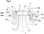
- the ring portion 3 comprises a plurality of rings placed one on top of the other along the center axis J.
- the rings are adjacent to each other.
- the middle ring 33 is made of plastic.
- the middle ring 33 has a bottom surface 330a, that faces the lower ring 31, and a top surface 330b that faces the upper ring 32.
- the bottom surface 330a and the top surface 330b each have a respective recess 301.
- This recess 301 has the purpose to reduce the weight of the structure and prevent warping of the lower ring 31 and the upper ring 32.
- the support element 2 comprises a bottom 9.
- This bottom 9 is placed transverse to the inner surface 7 and perpendicular to the center axis J.
- the bottom 9 defines an upper cavity 10 and a lower cavity 11 with the inner surface 7 of the support element 2.
- the cover element 4 is inserted into the upper cavity 10.
- the stopper 1 comprises a shank 13.
- the shank 13 is configured to fit into a bottle neck to close the bottle. More in detail, the shank 13 is inserted into the lower cavity 11. More in detail, the shank 13 extends along the center axis J, from the bottom 9 of the support element 2 away from the bottom 9. In particular, the shank 13 is joined to the support element 2. For example, the shank 13 is glued to the support element 2 or is mechanically fixed. This shank 13 is locked with respect to the support element 2, rotationally and along the center axis J.
- the stopper 1 comprises a threaded element 14.
- This threaded element 14 is configured to be coupled to a threaded bottle neck to close the bottle.
- the threaded element 14 is placed in the lower cavity 11.
- the support element 2 comprises one or more through openings 12.
- the through openings 12 of the present invention are configured to receive an adhesive between the support element 2 and the ring portion 3, to join the support element 2 to the ring portion 3.
- these through openings 12 are located at the lower cavity 11.
Landscapes
- Engineering & Computer Science (AREA)
- Mechanical Engineering (AREA)
- Closures For Containers (AREA)
Claims (13)
- Stopfen (1), der so konfiguriert ist, dass er auf den Hals einer Flasche aufgesetzt werden kann, umfassend:- ein Stützelement (2) mit einem oberen Rand (21) und einem unteren Rand (22), das sich entlang einer Mittelachse (J) erstreckt,- einen Ringabschnitt (3), der auf das Stützelement (2) passt und sich vom oberen Rand (21) zum unteren Rand (22) erstreckt, wobei der Ringabschnitt (3) mit dem Stützelement (2) verbunden ist, um in Bezug auf das Stützelement (2) drehschlüssig zu sein,- ein Abdeckelement (4), das am oberen Rand (21) mit dem Stützelement (2) gekoppelt und mit dem Ringabschnitt (3) verbunden ist, wobei der Ringabschnitt (3) durch das Stützelement (2) und durch das Abdeckelement (4) entlang der Mittelachse (J) verriegelt ist;dadurch gekennzeichnet, dass der Ringabschnitt (3) entlang der Mittelachse (J) relativ zu dem Stützelement (2) und dem Abdeckelement (4) vor und nach einem ersten Öffnen der Flasche stabil verriegelt ist.
- Stopfen (1) nach Anspruch 1, wobei der Ringabschnitt (3), das Stützelement (2) und das Abdeckelement (4) vor und nach einem ersten Öffnen der Flasche aneinander befestigt sind.
- Stopfen (1) nach einem der vorstehenden Ansprüche, wobei das Stützelement (2) ein unteres Anschlagelement (5) am unteren Rand (22) umfasst, wobei der Ringabschnitt (2) so konfiguriert ist, dass er an das untere Anschlagelement (5) anliegt.
- Stopfen (1) nach einem der vorstehenden Ansprüche, wobei das Abdeckelement (4) ein oberes Anschlagelement (6) umfasst, wobei der Ringabschnitt (3) so konfiguriert ist, dass er am oberen Rand (21) des Stützelements (2) an das obere Anschlagelement (6) anliegt.
- Stopfen (1) nach einem der vorstehenden Ansprüche, wobei das Stützelement (2) eine Innenfläche (7) aufweist, die das Abdeckelement (4) berührt, wobei die Innenfläche (7) und das Abdeckelement (4) jeweils zueinander komplementäre erste Verriegelungsabschnitte (71a, 71b) umfassen.
- Stopfen (1) nach einem der vorstehenden Ansprüche, wobei das Stützelement (2) eine Außenfläche (8) aufweist, die den Ringabschnitt (3) berührt, wobei die Außenfläche (8) und der Ringabschnitt (3) jeweils zueinander komplementäre zweite Verriegelungsabschnitte (81a, 81b) umfassen.
- Stopfen (1) nach einem der vorstehenden Ansprüche, wobei der Ringabschnitt (3) eine Vielzahl von Ringen umfasst, die entlang der Mittelachse (J) übereinander angeordnet sind.
- Stopfen (1) nach dem vorstehenden Anspruch, wobei der Ringabschnitt (3) einen unteren Ring (31), der am unteren Rand (22) angeordnet ist, einen oberen Ring (32), der am oberen Rand (21) angeordnet ist, und einen mittleren Ring (33) umfasst, wobei der mittlere Ring (33) eine untere Fläche (330a), die dem unteren Ring (31) zugewandt ist, und eine obere Fläche (330b), die dem oberen Ring (32) zugewandt ist, aufweist, wobei die untere Fläche (330a) und die obere Fläche (330b) entsprechende Aussparungen (301) aufweisen.
- Stopfen (1) nach Anspruch 5, wobei das Stützelement (2) einen Boden (9) umfasst, der quer zur Innenfläche (8) und senkrecht zur Mittelachse (J) angeordnet ist, wobei der Boden (9) einen oberen Hohlraum (10) und einen unteren Hohlraum (11) mit der Innenfläche (7) definiert.
- Stopfen (1) nach dem vorstehenden Anspruch, wobei das Abdeckelement (4) in den oberen Hohlraum (10) eingesetzt ist.
- Stopfen (1) nach Anspruch 9 oder 10, wobei das Stützelement (2) eine oder mehrere Durchgangsöffnungen (12) am unteren Hohlraum (11) umfasst, die es ermöglichen, das Stützelement (2) mit dem Ringabschnitt (3) zu verbinden.
- Stopfen (1) nach einem der Ansprüche 9 bis 11, umfassend einen Schaft (13), der in den unteren Hohlraum (11) passt und sich vom Boden (9) des Stützelements (2) aus erstreckt, wobei der Schaft (13) in Bezug auf das Stützelement (2) verriegelt ist und so konfiguriert ist, dass er in einen Flaschenhals passt, um die Flasche zu verschließen.
- Stopfen (1) nach einem der Ansprüche 9 bis 12, umfassend ein Gewindeelement (14), das so konfiguriert ist, dass es mit einem Flaschenhals mit Gewinde gekoppelt werden kann, um die Flasche zu verschließen, wobei das Gewindeelement (14) in dem unteren Hohlraum (11) angeordnet ist.
Applications Claiming Priority (2)
| Application Number | Priority Date | Filing Date | Title |
|---|---|---|---|
| IT102019000023058A IT201900023058A1 (it) | 2019-12-05 | 2019-12-05 | Tappo modulare. |
| PCT/IB2020/061483 WO2021111375A1 (en) | 2019-12-05 | 2020-12-04 | Modular plug |
Publications (2)
| Publication Number | Publication Date |
|---|---|
| EP4069603A1 EP4069603A1 (de) | 2022-10-12 |
| EP4069603B1 true EP4069603B1 (de) | 2025-03-19 |
Family
ID=70009246
Family Applications (1)
| Application Number | Title | Priority Date | Filing Date |
|---|---|---|---|
| EP20825242.9A Active EP4069603B1 (de) | 2019-12-05 | 2020-12-04 | Modularstopfer |
Country Status (4)
| Country | Link |
|---|---|
| EP (1) | EP4069603B1 (de) |
| IT (1) | IT201900023058A1 (de) |
| MX (1) | MX2022006826A (de) |
| WO (1) | WO2021111375A1 (de) |
Families Citing this family (1)
| Publication number | Priority date | Publication date | Assignee | Title |
|---|---|---|---|---|
| IT202100023294A1 (it) | 2021-09-09 | 2023-03-09 | Guala Closures Spa | Chiusura riciclabile |
Citations (1)
| Publication number | Priority date | Publication date | Assignee | Title |
|---|---|---|---|---|
| EP2765090B1 (de) * | 2013-02-08 | 2016-04-20 | Guala Closures S.p.A. | Originalitätsverschluss |
Family Cites Families (2)
| Publication number | Priority date | Publication date | Assignee | Title |
|---|---|---|---|---|
| FR2688762B1 (fr) * | 1992-03-20 | 1994-06-17 | Chauveau Joel | Dispositif d'obturation d'un recipient a temoin d'inviolabilite. |
| FR2770831B1 (fr) * | 1997-11-12 | 2000-01-21 | Niob Plastique | Capsule de bouchage pour col de flacon |
-
2019
- 2019-12-05 IT IT102019000023058A patent/IT201900023058A1/it unknown
-
2020
- 2020-12-04 EP EP20825242.9A patent/EP4069603B1/de active Active
- 2020-12-04 WO PCT/IB2020/061483 patent/WO2021111375A1/en not_active Ceased
- 2020-12-04 MX MX2022006826A patent/MX2022006826A/es unknown
Patent Citations (1)
| Publication number | Priority date | Publication date | Assignee | Title |
|---|---|---|---|---|
| EP2765090B1 (de) * | 2013-02-08 | 2016-04-20 | Guala Closures S.p.A. | Originalitätsverschluss |
Also Published As
| Publication number | Publication date |
|---|---|
| IT201900023058A1 (it) | 2021-06-05 |
| WO2021111375A1 (en) | 2021-06-10 |
| MX2022006826A (es) | 2022-09-23 |
| EP4069603A1 (de) | 2022-10-12 |
Similar Documents
| Publication | Publication Date | Title |
|---|---|---|
| US10118739B2 (en) | Child resistant closure for a container | |
| US3542256A (en) | Liquid container dispensing closures | |
| US20090050599A1 (en) | Supportable pressurizable container having a bottom for receiving a dip tube and base cup therefor | |
| US10472152B2 (en) | Container of a fluid substance and a transport system therefor | |
| EP3894336A1 (de) | Behälteranordnung | |
| RU2151090C1 (ru) | Колпачок для укупорки сосуда и его применение в качестве элемента строительного конструктора | |
| EP4069603A1 (de) | Modularstecker | |
| WO2021129931A1 (en) | Safe cap for a container | |
| ES2252022T3 (es) | Montaje de espita para contenedor. | |
| US20210107704A1 (en) | Stoppers with overcaps for containers | |
| US2951619A (en) | Pouring spout | |
| RU2258647C2 (ru) | Предохранительная крышка для бутылок и тому подобного | |
| EP3093256B1 (de) | Wiederbefüllen verhindernder ausgiesser für flasche | |
| EP0921077B1 (de) | Behälter-Vorrichtung mit abnehmbarem Kragen | |
| JP2011245146A (ja) | ミル容器 | |
| CN101125589A (zh) | 具备把手的广口pet容器 | |
| US20150183553A1 (en) | Set of Containers with Distinct Caps | |
| IT201900004383U1 (it) | Tappo modulare. | |
| KR20210006757A (ko) | 화장료 보존성이 증대된 화장품 용기 | |
| EP0870692A1 (de) | Kunststoffverschluss, insbesondere für Getränke enthaltende Flaschen | |
| KR20140000458U (ko) | 스크류식 합성수지 병뚜껑 | |
| WO2018035580A1 (en) | A container structure for detachable coupling of containers and system including same | |
| KR20250170369A (ko) | 잔으로 전환되는 용기 | |
| EP2133281A1 (de) | Behälter-Verschluss-Einheit für Flüssigkeiten mit einem Schnappverschluss | |
| KR20230002265U (ko) | 화장품 용기 |
Legal Events
| Date | Code | Title | Description |
|---|---|---|---|
| STAA | Information on the status of an ep patent application or granted ep patent |
Free format text: STATUS: UNKNOWN |
|
| STAA | Information on the status of an ep patent application or granted ep patent |
Free format text: STATUS: THE INTERNATIONAL PUBLICATION HAS BEEN MADE |
|
| PUAI | Public reference made under article 153(3) epc to a published international application that has entered the european phase |
Free format text: ORIGINAL CODE: 0009012 |
|
| STAA | Information on the status of an ep patent application or granted ep patent |
Free format text: STATUS: REQUEST FOR EXAMINATION WAS MADE |
|
| 17P | Request for examination filed |
Effective date: 20220704 |
|
| AK | Designated contracting states |
Kind code of ref document: A1 Designated state(s): AL AT BE BG CH CY CZ DE DK EE ES FI FR GB GR HR HU IE IS IT LI LT LU LV MC MK MT NL NO PL PT RO RS SE SI SK SM TR |
|
| DAV | Request for validation of the european patent (deleted) | ||
| DAX | Request for extension of the european patent (deleted) | ||
| GRAP | Despatch of communication of intention to grant a patent |
Free format text: ORIGINAL CODE: EPIDOSNIGR1 |
|
| STAA | Information on the status of an ep patent application or granted ep patent |
Free format text: STATUS: GRANT OF PATENT IS INTENDED |
|
| INTG | Intention to grant announced |
Effective date: 20241014 |
|
| GRAS | Grant fee paid |
Free format text: ORIGINAL CODE: EPIDOSNIGR3 |
|
| GRAA | (expected) grant |
Free format text: ORIGINAL CODE: 0009210 |
|
| STAA | Information on the status of an ep patent application or granted ep patent |
Free format text: STATUS: THE PATENT HAS BEEN GRANTED |
|
| AK | Designated contracting states |
Kind code of ref document: B1 Designated state(s): AL AT BE BG CH CY CZ DE DK EE ES FI FR GB GR HR HU IE IS IT LI LT LU LV MC MK MT NL NO PL PT RO RS SE SI SK SM TR |
|
| REG | Reference to a national code |
Ref country code: GB Ref legal event code: FG4D |
|
| REG | Reference to a national code |
Ref country code: CH Ref legal event code: EP |
|
| REG | Reference to a national code |
Ref country code: DE Ref legal event code: R096 Ref document number: 602020048039 Country of ref document: DE |
|
| REG | Reference to a national code |
Ref country code: IE Ref legal event code: FG4D |
|
| PG25 | Lapsed in a contracting state [announced via postgrant information from national office to epo] |
Ref country code: RS Free format text: LAPSE BECAUSE OF FAILURE TO SUBMIT A TRANSLATION OF THE DESCRIPTION OR TO PAY THE FEE WITHIN THE PRESCRIBED TIME-LIMIT Effective date: 20250619 |
|
| PG25 | Lapsed in a contracting state [announced via postgrant information from national office to epo] |
Ref country code: FI Free format text: LAPSE BECAUSE OF FAILURE TO SUBMIT A TRANSLATION OF THE DESCRIPTION OR TO PAY THE FEE WITHIN THE PRESCRIBED TIME-LIMIT Effective date: 20250319 |
|
| REG | Reference to a national code |
Ref country code: LT Ref legal event code: MG9D |
|
| PG25 | Lapsed in a contracting state [announced via postgrant information from national office to epo] |
Ref country code: NO Free format text: LAPSE BECAUSE OF FAILURE TO SUBMIT A TRANSLATION OF THE DESCRIPTION OR TO PAY THE FEE WITHIN THE PRESCRIBED TIME-LIMIT Effective date: 20250619 |
|
| P01 | Opt-out of the competence of the unified patent court (upc) registered |
Free format text: CASE NUMBER: APP_27901/2025 Effective date: 20250611 |
|
| PG25 | Lapsed in a contracting state [announced via postgrant information from national office to epo] |
Ref country code: HR Free format text: LAPSE BECAUSE OF FAILURE TO SUBMIT A TRANSLATION OF THE DESCRIPTION OR TO PAY THE FEE WITHIN THE PRESCRIBED TIME-LIMIT Effective date: 20250319 |
|
| PG25 | Lapsed in a contracting state [announced via postgrant information from national office to epo] |
Ref country code: LV Free format text: LAPSE BECAUSE OF FAILURE TO SUBMIT A TRANSLATION OF THE DESCRIPTION OR TO PAY THE FEE WITHIN THE PRESCRIBED TIME-LIMIT Effective date: 20250319 |
|
| PG25 | Lapsed in a contracting state [announced via postgrant information from national office to epo] |
Ref country code: GR Free format text: LAPSE BECAUSE OF FAILURE TO SUBMIT A TRANSLATION OF THE DESCRIPTION OR TO PAY THE FEE WITHIN THE PRESCRIBED TIME-LIMIT Effective date: 20250620 |
|
| REG | Reference to a national code |
Ref country code: NL Ref legal event code: MP Effective date: 20250319 |
|
| REG | Reference to a national code |
Ref country code: AT Ref legal event code: MK05 Ref document number: 1776807 Country of ref document: AT Kind code of ref document: T Effective date: 20250319 |
|
| PG25 | Lapsed in a contracting state [announced via postgrant information from national office to epo] |
Ref country code: NL Free format text: LAPSE BECAUSE OF FAILURE TO SUBMIT A TRANSLATION OF THE DESCRIPTION OR TO PAY THE FEE WITHIN THE PRESCRIBED TIME-LIMIT Effective date: 20250319 |
|
| PG25 | Lapsed in a contracting state [announced via postgrant information from national office to epo] |
Ref country code: SE Free format text: LAPSE BECAUSE OF FAILURE TO SUBMIT A TRANSLATION OF THE DESCRIPTION OR TO PAY THE FEE WITHIN THE PRESCRIBED TIME-LIMIT Effective date: 20250319 |
|
| PG25 | Lapsed in a contracting state [announced via postgrant information from national office to epo] |
Ref country code: SM Free format text: LAPSE BECAUSE OF FAILURE TO SUBMIT A TRANSLATION OF THE DESCRIPTION OR TO PAY THE FEE WITHIN THE PRESCRIBED TIME-LIMIT Effective date: 20250319 |
|
| PG25 | Lapsed in a contracting state [announced via postgrant information from national office to epo] |
Ref country code: ES Free format text: LAPSE BECAUSE OF FAILURE TO SUBMIT A TRANSLATION OF THE DESCRIPTION OR TO PAY THE FEE WITHIN THE PRESCRIBED TIME-LIMIT Effective date: 20250319 Ref country code: PT Free format text: LAPSE BECAUSE OF FAILURE TO SUBMIT A TRANSLATION OF THE DESCRIPTION OR TO PAY THE FEE WITHIN THE PRESCRIBED TIME-LIMIT Effective date: 20250721 |
|
| PG25 | Lapsed in a contracting state [announced via postgrant information from national office to epo] |
Ref country code: PL Free format text: LAPSE BECAUSE OF FAILURE TO SUBMIT A TRANSLATION OF THE DESCRIPTION OR TO PAY THE FEE WITHIN THE PRESCRIBED TIME-LIMIT Effective date: 20250319 Ref country code: IT Free format text: LAPSE BECAUSE OF FAILURE TO SUBMIT A TRANSLATION OF THE DESCRIPTION OR TO PAY THE FEE WITHIN THE PRESCRIBED TIME-LIMIT Effective date: 20250319 |
|
| PG25 | Lapsed in a contracting state [announced via postgrant information from national office to epo] |
Ref country code: AT Free format text: LAPSE BECAUSE OF FAILURE TO SUBMIT A TRANSLATION OF THE DESCRIPTION OR TO PAY THE FEE WITHIN THE PRESCRIBED TIME-LIMIT Effective date: 20250319 |
|
| PG25 | Lapsed in a contracting state [announced via postgrant information from national office to epo] |
Ref country code: CZ Free format text: LAPSE BECAUSE OF FAILURE TO SUBMIT A TRANSLATION OF THE DESCRIPTION OR TO PAY THE FEE WITHIN THE PRESCRIBED TIME-LIMIT Effective date: 20250319 Ref country code: EE Free format text: LAPSE BECAUSE OF FAILURE TO SUBMIT A TRANSLATION OF THE DESCRIPTION OR TO PAY THE FEE WITHIN THE PRESCRIBED TIME-LIMIT Effective date: 20250319 |
|
| PG25 | Lapsed in a contracting state [announced via postgrant information from national office to epo] |
Ref country code: RO Free format text: LAPSE BECAUSE OF FAILURE TO SUBMIT A TRANSLATION OF THE DESCRIPTION OR TO PAY THE FEE WITHIN THE PRESCRIBED TIME-LIMIT Effective date: 20250319 |
|
| PG25 | Lapsed in a contracting state [announced via postgrant information from national office to epo] |
Ref country code: SK Free format text: LAPSE BECAUSE OF FAILURE TO SUBMIT A TRANSLATION OF THE DESCRIPTION OR TO PAY THE FEE WITHIN THE PRESCRIBED TIME-LIMIT Effective date: 20250319 |
|
| PG25 | Lapsed in a contracting state [announced via postgrant information from national office to epo] |
Ref country code: IS Free format text: LAPSE BECAUSE OF FAILURE TO SUBMIT A TRANSLATION OF THE DESCRIPTION OR TO PAY THE FEE WITHIN THE PRESCRIBED TIME-LIMIT Effective date: 20250719 |
|
| REG | Reference to a national code |
Ref country code: DE Ref legal event code: R097 Ref document number: 602020048039 Country of ref document: DE |
|
| PG25 | Lapsed in a contracting state [announced via postgrant information from national office to epo] |
Ref country code: DK Free format text: LAPSE BECAUSE OF FAILURE TO SUBMIT A TRANSLATION OF THE DESCRIPTION OR TO PAY THE FEE WITHIN THE PRESCRIBED TIME-LIMIT Effective date: 20250319 |
|
| PGFP | Annual fee paid to national office [announced via postgrant information from national office to epo] |
Ref country code: BG Payment date: 20251219 Year of fee payment: 6 |
|
| PLBE | No opposition filed within time limit |
Free format text: ORIGINAL CODE: 0009261 |
|
| STAA | Information on the status of an ep patent application or granted ep patent |
Free format text: STATUS: NO OPPOSITION FILED WITHIN TIME LIMIT |
|
| REG | Reference to a national code |
Ref country code: CH Ref legal event code: L10 Free format text: ST27 STATUS EVENT CODE: U-0-0-L10-L00 (AS PROVIDED BY THE NATIONAL OFFICE) Effective date: 20260128 |
|
| 26N | No opposition filed |
Effective date: 20251222 |