EP4068618A1 - Motorantriebsvorrichtung, elektrischer staubsauger und handtrockner - Google Patents
Motorantriebsvorrichtung, elektrischer staubsauger und handtrockner Download PDFInfo
- Publication number
- EP4068618A1 EP4068618A1 EP19954670.6A EP19954670A EP4068618A1 EP 4068618 A1 EP4068618 A1 EP 4068618A1 EP 19954670 A EP19954670 A EP 19954670A EP 4068618 A1 EP4068618 A1 EP 4068618A1
- Authority
- EP
- European Patent Office
- Prior art keywords
- pulse
- motor
- current
- switching element
- inverter
- Prior art date
- Legal status (The legal status is an assumption and is not a legal conclusion. Google has not performed a legal analysis and makes no representation as to the accuracy of the status listed.)
- Withdrawn
Links
Images






Classifications
-
- H—ELECTRICITY
- H02—GENERATION; CONVERSION OR DISTRIBUTION OF ELECTRIC POWER
- H02P—CONTROL OR REGULATION OF ELECTRIC MOTORS, ELECTRIC GENERATORS OR DYNAMO-ELECTRIC CONVERTERS; CONTROLLING TRANSFORMERS, REACTORS OR CHOKE COILS
- H02P6/00—Arrangements for controlling synchronous motors or other dynamo-electric motors using electronic commutation dependent on the rotor position; Electronic commutators therefor
- H02P6/06—Arrangements for speed regulation of a single motor wherein the motor speed is measured and compared with a given physical value so as to adjust the motor speed
-
- H—ELECTRICITY
- H02—GENERATION; CONVERSION OR DISTRIBUTION OF ELECTRIC POWER
- H02P—CONTROL OR REGULATION OF ELECTRIC MOTORS, ELECTRIC GENERATORS OR DYNAMO-ELECTRIC CONVERTERS; CONTROLLING TRANSFORMERS, REACTORS OR CHOKE COILS
- H02P6/00—Arrangements for controlling synchronous motors or other dynamo-electric motors using electronic commutation dependent on the rotor position; Electronic commutators therefor
- H02P6/26—Arrangements for controlling single phase motors
Definitions
- a motor driver includes an inverter and a current detector.
- the inverter includes: a first leg including a first switching element of an upper arm and a second switching element of a lower arm connected in series; and a second leg including a third switching element of the upper arm and a fourth switching element of the lower arm connected in series.
- the first leg and a second leg are connected in parallel with a direct-current power supply.
- the inverter converts direct-current power supplied from the direct-current power supply into alternating-current power, and supplies the alternating-current power to a single-phase motor.
- the current detector is disposed on a path between the inverter and the direct-current power supply.
- MOSFETs Metal-oxide-semiconductor field-effect transistors
- FETs field-effect transistors
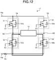
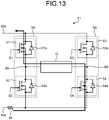
- FIGS. 13 and 14 both illustrate operations when the energy of the single-phase motor 12 is regenerated into the battery 10.
- the driving signals S1 and S4 turn the switching elements 51 and 54 ON, and regenerative current flowing out from the single-phase motor 12 returns to the single-phase motor 12 via the switching element 51, the battery 10, which is not illustrated in FIG. 13 , the shunt resistor 55, and the switching element 54.
- the driving signals S2 and S3 turn the switching elements 52 and 53 ON, and regenerative current flowing out from the single-phase motor 12 returns to the single-phase motor 12 via the switching element 53, the battery 10, which is not illustrated in FIG. 14 , the shunt resistor 55, and the switching element 52. In either case, current flows to the shunt resistor 55.
Landscapes
- Engineering & Computer Science (AREA)
- Power Engineering (AREA)
- Control Of Ac Motors In General (AREA)
- Inverter Devices (AREA)
- Control Of Motors That Do Not Use Commutators (AREA)
Applications Claiming Priority (1)
| Application Number | Priority Date | Filing Date | Title |
|---|---|---|---|
| PCT/JP2019/046802 WO2021106195A1 (ja) | 2019-11-29 | 2019-11-29 | モータ駆動装置、電気掃除機及び手乾燥機 |
Publications (2)
| Publication Number | Publication Date |
|---|---|
| EP4068618A1 true EP4068618A1 (de) | 2022-10-05 |
| EP4068618A4 EP4068618A4 (de) | 2022-11-23 |
Family
ID=76129287
Family Applications (1)
| Application Number | Title | Priority Date | Filing Date |
|---|---|---|---|
| EP19954670.6A Withdrawn EP4068618A4 (de) | 2019-11-29 | 2019-11-29 | Motorantriebsvorrichtung, elektrischer staubsauger und handtrockner |
Country Status (3)
| Country | Link |
|---|---|
| EP (1) | EP4068618A4 (de) |
| JP (1) | JP7237197B2 (de) |
| WO (1) | WO2021106195A1 (de) |
Families Citing this family (2)
| Publication number | Priority date | Publication date | Assignee | Title |
|---|---|---|---|---|
| KR102288799B1 (ko) | 2017-09-27 | 2021-08-11 | 현대모비스 주식회사 | 군집주행 제어 장치 및 방법 |
| JP7522138B2 (ja) * | 2021-08-05 | 2024-07-24 | 寧徳時代新能源科技股▲分▼有限公司 | 動力電池加熱システム、その制御方法及び制御回路 |
Family Cites Families (8)
| Publication number | Priority date | Publication date | Assignee | Title |
|---|---|---|---|---|
| JP4779565B2 (ja) | 2005-10-20 | 2011-09-28 | オムロン株式会社 | インバータ制御回路 |
| JP4866216B2 (ja) | 2006-11-22 | 2012-02-01 | 株式会社日立製作所 | 電力変換装置 |
| WO2010103565A1 (ja) | 2009-03-10 | 2010-09-16 | 株式会社日立産機システム | 交流電動機の駆動装置 |
| GB2469127A (en) * | 2009-04-04 | 2010-10-06 | Dyson Technology Ltd | Overcurrent control system for an electric machine |
| GB201006392D0 (en) * | 2010-04-16 | 2010-06-02 | Dyson Technology Ltd | Controller for a brushless motor |
| JP2015023773A (ja) | 2013-07-23 | 2015-02-02 | アイシン・エィ・ダブリュ株式会社 | 駆動装置 |
| GB2549742B (en) | 2016-04-26 | 2020-06-17 | Dyson Technology Ltd | Method of determining the rotor position of a permanent-magnet motor |
| WO2019180936A1 (ja) | 2018-03-23 | 2019-09-26 | 三菱電機株式会社 | 電動送風機、電気掃除機および手乾燥装置 |
-
2019
- 2019-11-29 WO PCT/JP2019/046802 patent/WO2021106195A1/ja not_active Ceased
- 2019-11-29 EP EP19954670.6A patent/EP4068618A4/de not_active Withdrawn
- 2019-11-29 JP JP2021561107A patent/JP7237197B2/ja active Active
Also Published As
| Publication number | Publication date |
|---|---|
| WO2021106195A1 (ja) | 2021-06-03 |
| JPWO2021106195A1 (de) | 2021-06-03 |
| EP4068618A4 (de) | 2022-11-23 |
| JP7237197B2 (ja) | 2023-03-10 |
Similar Documents
| Publication | Publication Date | Title |
|---|---|---|
| CN111869098B (zh) | 马达驱动装置、电动送风机、吸尘器以及干手器 | |
| JP6644159B2 (ja) | モータ駆動装置、電動送風機、電気掃除機及びハンドドライヤー | |
| JP6800329B2 (ja) | モータ駆動装置、電動送風機、電気掃除機及びハンドドライヤ | |
| US11316465B2 (en) | Motor drive device, electric blower, electric vacuum cleaner, and hand dryer | |
| EP4068618A1 (de) | Motorantriebsvorrichtung, elektrischer staubsauger und handtrockner | |
| EP4068617A1 (de) | Motorantriebsvorrichtung, elektrischer staubsauger und handtrockner | |
| JP6847195B2 (ja) | モータ駆動装置、電動送風機、電気掃除機及びハンドドライヤー | |
| US11611306B2 (en) | Motor driving apparatus, electric blower, vacuum cleaner, and hand dryer | |
| EP3952103A1 (de) | Motorantriebsvorrichtung, elektrischer staubsauger und handtrockner | |
| EP3955455B1 (de) | Motorantriebsvorrichtung | |
| US11863104B2 (en) | Motor drive device, electric blower, electric vacuum cleaner, and hand dryer | |
| JP6616055B1 (ja) | モータ駆動装置、電気掃除機及び手乾燥機 | |
| JP7462788B2 (ja) | モータ駆動装置、電動送風機、電気掃除機及びハンドドライヤ | |
| JP7150152B2 (ja) | モータ駆動装置、電動送風機、電気掃除機及びハンドドライヤ | |
| JPWO2020208785A1 (ja) | モータ駆動装置、電動送風機、電気掃除機及びハンドドライヤ | |
| WO2023181181A1 (ja) | モータ駆動装置、電動送風機、電気掃除機及びハンドドライヤ | |
| WO2019180969A1 (ja) | モータ駆動装置、電動送風機、電気掃除機及びハンドドライヤ | |
| JPWO2019180967A1 (ja) | モータ駆動装置、電気掃除機及び手乾燥機 |
Legal Events
| Date | Code | Title | Description |
|---|---|---|---|
| STAA | Information on the status of an ep patent application or granted ep patent |
Free format text: STATUS: THE INTERNATIONAL PUBLICATION HAS BEEN MADE |
|
| PUAI | Public reference made under article 153(3) epc to a published international application that has entered the european phase |
Free format text: ORIGINAL CODE: 0009012 |
|
| STAA | Information on the status of an ep patent application or granted ep patent |
Free format text: STATUS: REQUEST FOR EXAMINATION WAS MADE |
|
| 17P | Request for examination filed |
Effective date: 20220331 |
|
| AK | Designated contracting states |
Kind code of ref document: A1 Designated state(s): AL AT BE BG CH CY CZ DE DK EE ES FI FR GB GR HR HU IE IS IT LI LT LU LV MC MK MT NL NO PL PT RO RS SE SI SK SM TR |
|
| A4 | Supplementary search report drawn up and despatched |
Effective date: 20221026 |
|
| RIC1 | Information provided on ipc code assigned before grant |
Ipc: H02P 6/06 20060101ALI20221020BHEP Ipc: H02P 27/06 20060101AFI20221020BHEP |
|
| DAV | Request for validation of the european patent (deleted) | ||
| DAX | Request for extension of the european patent (deleted) | ||
| STAA | Information on the status of an ep patent application or granted ep patent |
Free format text: STATUS: EXAMINATION IS IN PROGRESS |
|
| 17Q | First examination report despatched |
Effective date: 20231214 |
|
| STAA | Information on the status of an ep patent application or granted ep patent |
Free format text: STATUS: THE APPLICATION IS DEEMED TO BE WITHDRAWN |
|
| 18D | Application deemed to be withdrawn |
Effective date: 20250603 |