EP4067784A1 - Kühlschrank mit modul mit mehreren speicherkammern - Google Patents
Kühlschrank mit modul mit mehreren speicherkammern Download PDFInfo
- Publication number
- EP4067784A1 EP4067784A1 EP20894808.3A EP20894808A EP4067784A1 EP 4067784 A1 EP4067784 A1 EP 4067784A1 EP 20894808 A EP20894808 A EP 20894808A EP 4067784 A1 EP4067784 A1 EP 4067784A1
- Authority
- EP
- European Patent Office
- Prior art keywords
- refrigerator
- cooling plate
- cabinet
- storage chamber
- radiational cooling
- Prior art date
- Legal status (The legal status is an assumption and is not a legal conclusion. Google has not performed a legal analysis and makes no representation as to the accuracy of the status listed.)
- Pending
Links
Images





Classifications
-
- F—MECHANICAL ENGINEERING; LIGHTING; HEATING; WEAPONS; BLASTING
- F25—REFRIGERATION OR COOLING; COMBINED HEATING AND REFRIGERATION SYSTEMS; HEAT PUMP SYSTEMS; MANUFACTURE OR STORAGE OF ICE; LIQUEFACTION SOLIDIFICATION OF GASES
- F25D—REFRIGERATORS; COLD ROOMS; ICE-BOXES; COOLING OR FREEZING APPARATUS NOT OTHERWISE PROVIDED FOR
- F25D13/00—Stationary devices, e.g. cold-rooms
- F25D13/02—Stationary devices, e.g. cold-rooms with several cooling compartments, e.g. refrigerated locker systems
-
- F—MECHANICAL ENGINEERING; LIGHTING; HEATING; WEAPONS; BLASTING
- F25—REFRIGERATION OR COOLING; COMBINED HEATING AND REFRIGERATION SYSTEMS; HEAT PUMP SYSTEMS; MANUFACTURE OR STORAGE OF ICE; LIQUEFACTION SOLIDIFICATION OF GASES
- F25D—REFRIGERATORS; COLD ROOMS; ICE-BOXES; COOLING OR FREEZING APPARATUS NOT OTHERWISE PROVIDED FOR
- F25D19/00—Arrangement or mounting of refrigeration units with respect to devices or objects to be refrigerated, e.g. infrared detectors
- F25D19/02—Arrangement or mounting of refrigeration units with respect to devices or objects to be refrigerated, e.g. infrared detectors plug-in type
-
- F—MECHANICAL ENGINEERING; LIGHTING; HEATING; WEAPONS; BLASTING
- F25—REFRIGERATION OR COOLING; COMBINED HEATING AND REFRIGERATION SYSTEMS; HEAT PUMP SYSTEMS; MANUFACTURE OR STORAGE OF ICE; LIQUEFACTION SOLIDIFICATION OF GASES
- F25D—REFRIGERATORS; COLD ROOMS; ICE-BOXES; COOLING OR FREEZING APPARATUS NOT OTHERWISE PROVIDED FOR
- F25D17/00—Arrangements for circulating cooling fluids; Arrangements for circulating gas, e.g. air, within refrigerated spaces
-
- F—MECHANICAL ENGINEERING; LIGHTING; HEATING; WEAPONS; BLASTING
- F25—REFRIGERATION OR COOLING; COMBINED HEATING AND REFRIGERATION SYSTEMS; HEAT PUMP SYSTEMS; MANUFACTURE OR STORAGE OF ICE; LIQUEFACTION SOLIDIFICATION OF GASES
- F25D—REFRIGERATORS; COLD ROOMS; ICE-BOXES; COOLING OR FREEZING APPARATUS NOT OTHERWISE PROVIDED FOR
- F25D19/00—Arrangement or mounting of refrigeration units with respect to devices or objects to be refrigerated, e.g. infrared detectors
- F25D19/04—Arrangement or mounting of refrigeration units with respect to devices or objects to be refrigerated, e.g. infrared detectors with more than one refrigeration unit
-
- F—MECHANICAL ENGINEERING; LIGHTING; HEATING; WEAPONS; BLASTING
- F25—REFRIGERATION OR COOLING; COMBINED HEATING AND REFRIGERATION SYSTEMS; HEAT PUMP SYSTEMS; MANUFACTURE OR STORAGE OF ICE; LIQUEFACTION SOLIDIFICATION OF GASES
- F25D—REFRIGERATORS; COLD ROOMS; ICE-BOXES; COOLING OR FREEZING APPARATUS NOT OTHERWISE PROVIDED FOR
- F25D21/00—Defrosting; Preventing frosting; Removing condensed or defrost water
- F25D21/14—Collecting or removing condensed and defrost water; Drip trays
-
- F—MECHANICAL ENGINEERING; LIGHTING; HEATING; WEAPONS; BLASTING
- F25—REFRIGERATION OR COOLING; COMBINED HEATING AND REFRIGERATION SYSTEMS; HEAT PUMP SYSTEMS; MANUFACTURE OR STORAGE OF ICE; LIQUEFACTION SOLIDIFICATION OF GASES
- F25D—REFRIGERATORS; COLD ROOMS; ICE-BOXES; COOLING OR FREEZING APPARATUS NOT OTHERWISE PROVIDED FOR
- F25D29/00—Arrangement or mounting of control or safety devices
-
- F—MECHANICAL ENGINEERING; LIGHTING; HEATING; WEAPONS; BLASTING
- F25—REFRIGERATION OR COOLING; COMBINED HEATING AND REFRIGERATION SYSTEMS; HEAT PUMP SYSTEMS; MANUFACTURE OR STORAGE OF ICE; LIQUEFACTION SOLIDIFICATION OF GASES
- F25D—REFRIGERATORS; COLD ROOMS; ICE-BOXES; COOLING OR FREEZING APPARATUS NOT OTHERWISE PROVIDED FOR
- F25D2400/00—General features of, or devices for refrigerators, cold rooms, ice-boxes, or for cooling or freezing apparatus not covered by any other subclass
- F25D2400/36—Visual displays
Definitions
- the present disclosure relates to a refrigerator, and relates to a refrigerator including one module or a plurality of modules having a plurality of rooms (storage chambers).
- a refrigerator is an apparatus for refrigerating or freezing a stored product and is used in homes and businesses such as restaurants.
- a general refrigerator is often used by family members or business members.
- a space used by the multiple users for example, in a space (hereinafter, referred to as a "shared space") such as an office, a hospital, a shared house, a dormitory, or a school.
- a space such as an office, a hospital, a shared house, a dormitory, or a school.
- shared space such as an office, a hospital, a shared house, a dormitory, or a school.
- the present disclosure is to provide a new type of shared refrigerator that may be installed in a shared space.
- the present disclosure is to provide a refrigerator having a refrigerator module in which a plurality of rooms are opened and closed by individual doors.
- the present disclosure is to provide a refrigerator capable of easily expanding the number of rooms by making it easy to vertically or horizontally expand a refrigerator module according to one embodiment of the present disclosure.
- the present disclosure is to provide a refrigerator that may easily form a refrigerator module via one cold air flow path structure and one machine room according to one embodiment of the present disclosure.
- the present disclosure is to provide a refrigerator capable of increasing usage satisfaction and independently cooling each room by excluding sharing of cold air between a plurality of rooms according to one embodiment of the present disclosure.
- the present disclosure is to provide a refrigerator capable of temporarily storing fresh food after refrigerated delivery or directly delivering the fresh food to a refrigerator of a user according to one embodiment of the present disclosure.
- a refrigerator including a plurality of refrigerator modules, wherein each refrigerator module includes a cabinet forming an appearance of the refrigerator module and having a plurality of storage chambers therein, each door disposed in the cabinet and disposed for each storage chamber, each radiational cooling plate for forming a rear wall of each storage chamber, wherein the radiational cooling plate is disposed to block air communication between an interior of the storage chamber and an interior of another storage chamber, wherein the radiational cooling plate cools the interior of the storage chamber through radiational cooling, a refrigerant pipe flow path located in the rear of the radiational cooling plate to exchange heat with the radiational cooling plate, and a machine room for discharging a refrigerant to the refrigerant pipe flow path and sucking the refrigerant that has exchanged heat with the radiational cooling plate.
- the plurality of storage chambers are arranged in a vertical direction, and the machine room is disposed beneath the refrigerator module.
- the plurality of refrigerator modules are arranged to be in close contact with each other in a horizontal direction such that the number of the storage chambers increases in the horizontal direction.
- each refrigerator module includes each machine room, and the refrigerator includes a base cover for covering the plurality of machine rooms from the front.
- the refrigerator further includes a decor for covering a gap in the horizontal direction between the refrigerator modules from the rear of the cabinet.
- the door has a user interface for authenticating a user.
- the user interface includes an NFC communication module.
- the cabinet is integrally formed to integrally accommodate the plurality of storage chambers therein.
- the cabinet includes a plurality of cabinets separately formed to respectively accommodate the plurality of storage chambers therein and coupled to each other.
- each cabinet includes a coupling portion movable between an interior of the cabinet and an exterior of the cabinet by pivoting, and adjacent cabinets are coupled to each other by mating of coupling portions thereof.
- each coupling portion includes a protrusion and an accommodating portion, and a protrusion of one coupling portion is inserted into an accommodating portion of another coupling portion.
- each radiational cooling plate is disposed on the rear wall of each storage chamber, and a radiational cooling plate of one storage chamber is separately formed from a radiational cooling plate of another storage chamber.
- the refrigerant pipe flow path is disposed to be in close contact with each of the plurality of radiational cooling plates.
- the radiational cooling plate and the refrigerant pipe flow path are integrally formed.
- each insertion hole is defined in each of a top face and a bottom face of the cabinet such that the refrigerant pipe flow path is inserted into and extends through the cabinet.
- the radiational cooling plates are integrally formed to be a single radiational cooling plate, so that the single radiational cooling plate forms the rear walls of the plurality of storage chambers.
- the radiational cooling plate and the refrigerant pipe flow path are integrally formed.
- each insertion hole is defined in each of a top face and a bottom face of the cabinet such that the single radiational cooling plate and a cold air circulating flow path are inserted into and extend through the cabinet.
- each opening is defined in each of a top face and a bottom face of the cabinet such that a defrosting water line extends through the cabinet.
- the defrosting water line vertically extends through the plurality of storage chambers and then extends to a bottom face of an uppermost storage chamber.
- a refrigerator including a plurality of refrigerator modules, wherein each refrigerator module includes a cabinet forming an appearance of the refrigerator module and having a plurality of storage chambers therein, each door disposed in the cabinet and disposed for each storage chamber, each radiational cooling plate for forming a rear wall of each storage chamber, wherein the radiational cooling plate is disposed to block air communication between an interior of the storage chamber and an interior of another storage chamber, wherein the radiational cooling plate cools the interior of the storage chamber through radiational cooling, a cold air circulating flow path located in the rear of the radiational cooling plate to supply cold air for heat exchange with the radiational cooling plate, and a machine room for discharging cold air to the cold air circulating flow path and sucking cold air that has exchanged heat with the radiational cooling plate.
- the plurality of storage chambers are arranged in a vertical direction, and the machine room is disposed beneath the refrigerator module.
- the plurality of refrigerator modules are arranged to be in close contact with each other in a horizontal direction such that the number of the storage chambers increases in the horizontal direction.
- each refrigerator module includes each machine room, and the refrigerator includes a base cover for covering the plurality of machine rooms from the front.
- the refrigerator further includes a decor for covering a gap in the horizontal direction between the refrigerator modules from the rear of the cabinet.
- the door has a user interface for authenticating a user.
- the user interface includes an NFC communication module.
- the cabinet is integrally formed to integrally accommodate the plurality of storage chambers therein.
- the cabinet includes a plurality of cabinets separately formed to respectively accommodate the plurality of storage chambers therein and coupled to each other.
- each cabinet includes a coupling portion movable between an interior of the cabinet and an exterior of the cabinet by pivoting, and adjacent cabinets are coupled to each other by mating of coupling portions thereof.
- each coupling portion includes a protrusion and an accommodating portion, and a protrusion of one coupling portion is inserted into an accommodating portion of another coupling portion.
- each radiational cooling plate is disposed on the rear wall of each storage chamber, and a radiational cooling plate of one storage chamber is separately formed from a radiational cooling plate of another storage chamber.
- the cold air circulating flow path is integrally defined to cool all of the plurality of radiational cooling plates.
- each insertion hole is defined in each of a top face and a bottom face of the cabinet such that the cold air circulating flow path is inserted into and extends through the cabinet.
- the radiational cooling plates are integrally formed to be a single radiational cooling plate, so that the single radiational cooling plate forms the rear walls of the plurality of storage chambers.
- the cold air circulating flow path is integrally defined to cool the single radiational cooling plate.
- each insertion hole is defined in each of a top face and a bottom face of the cabinet such that the single radiational cooling plate and the cold air circulating flow path are inserted into and extend through the cabinet.
- each opening is defined in each of a top face and a bottom face of the cabinet such that a defrosting water line extends through the cabinet.
- the defrosting water line vertically extends through the plurality of storage chambers and then extends to a bottom face of an uppermost storage chamber.
- the cold air circulating flow path and the refrigerant pipe flow path may be referred to as cooling apparatuses that cool the radiational cooling plate outside the storage chamber.
- the radiational cooling plate may be exposed to the interior of the storage chamber and may be sealed from the exterior of the storage chamber. Therefore, entrance and exit of cold air between one storage chamber and an adjacent storage chamber is blocked.
- the cooling apparatus may be referred to as a component that directly cools the radiational cooling plate from the rear of the radiational cooling plate, that is, outside the storage chamber.
- a cooling method one of radiational cooling plate cooling by cold air and radiational cooling plate cooling by a refrigerant may be applied.
- the refrigerator having the refrigerator module in which the plurality of rooms are opened and closed by the individual doors may be provided.
- the refrigerator capable of easily expanding the number of rooms by making it easy to vertically or horizontally expand the refrigerator module may be provided.
- the refrigerator that may easily form the refrigerator module via one cold air flow path structure and one machine room may be provided.
- the refrigerator capable of increasing the usage satisfaction and independently cooling each room by excluding the sharing of the cold air between the plurality of rooms may be provided.
- the refrigerator capable of temporarily storing the fresh food after the refrigerated delivery or directly delivering the fresh food to the refrigerator of the user may be provided.
- FIG. 1 shows a concept of a refrigerator according to an embodiment of the present disclosure.
- the refrigerator according to the present embodiment will be referred to as a shared refrigerator in order to be distinguished from a general refrigerator.
- a shared refrigerator 1 may include a plurality of rooms (storage chambers) 23 and a machine room 30. Each of the plurality of rooms may have a door 22 for opening and closing the room.
- cooling unit 20 one room and one door may be referred to as a cooling unit 20 for convenience.
- the cooling unit may include a cabinet 21 that forms an appearance and defines the storage chamber therein.
- the cabinet may be separately formed for each single cooling unit, and the cabinet may be formed as a whole module forming a plurality of cooling units.
- a single cooling unit 20 may perform a function as a refrigerator for refrigerating a stored product or a function as a freezer for freezing the store product.
- the single cooling unit may be specialized as the refrigerator or may be specialized as the freezer.
- switching between the refrigerator and the freezer may be performed by storage temperature setting.
- the single cooling unit may be assigned to a specific user. That is, it is possible to assign the cooling unit for each user. In this case, a specific user is able to only use a specific cooling unit.
- a user interface 20 may be disposed on a front face of the door 22.
- the user interface may be disposed for user authentication.
- the door 22 may be opened. That is, it is possible to prevent an unauthorized user from opening the door.
- a door locking device may be disposed.
- the user interface 20 may be equipped for short-range wireless communication with a portable terminal.
- the user interface 20 may have an NFC communication module. Accordingly, the user may be authenticated as the user by tagging a portable terminal thereof on the user interface 20.
- the shared refrigerator 1 may be used for commercial purposes. That is, a provider of the entire shared refrigerator 1 and the user who leases each unit 20 may be distinguished. In addition, an application for remotely managing the shared refrigerator 1 may be installed in portable terminals of the provider and the user.
- the provider and the user may use various remote services such as payment, use approval, and remote control of the refrigerator using the portable terminals.
- the user may remotely open a door of the unit used by himself/herself. That is, the locking device of the door may be remotely released. A person who delivers fresh food may directly put the fresh food into the user's unit. Therefore, freshness of the fresh food may be maintained and overpacking may be prevented in advance.
- the person who delivers the fresh food may also get permission to use the user's unit in advance.
- a password for opening the door may be delivered to the delivery person.
- the user may deliver location information of the shared refrigerator and the unit thereof, the password, and the like to the delivery person as delivery information.
- the delivery person may also remotely request the user to unlock the door.
- the shared refrigerator may be installed in an entrance lobby of a dormitory.
- a person who placed an order does not need to directly receive the fresh food. That is, the delivery person does not need to directly deliver the fresh food to the person who placed the order. This is because the delivery person is able to put the fresh food directly into a unit of the person who placed the order.
- Information such as the number of door openings or an opening time may be stored through an application of a portable terminal of the person who placed the order.
- the unit may be equipped with a camera module for photographing an interior of the storage chamber.
- the camera module photographs the interior of the storage chamber
- the stored product inside the storage chamber may be identified.
- the user the person who placed the order
- the shared refrigerator may perform a function of storing an object as well as a function of a delivered product storage.
- one of the cooling units may be provided as a unit that may be shared without being assigned to the user.
- an ice maker unit for supplying ice or a water purifier unit for supplying purified water may be disposed.
- Such an ice maker unit or a water purifier unit may not have the door unlike other units.
- FIG. 1 shows the shared refrigerator 1 in which the cooling units are arranged in 3 horizontal rows and 3 vertical columns, and shows an example in which the water purifier unit is disposed in a third row and a second column.
- the machine room 30 for operating all of the cooling units is disposed at a bottom of the shared refrigerator 1 is shown.
- the shared refrigerator may include a refrigerator module.
- the refrigerator module may include a plurality of units.
- the shared refrigerator may be composed of three refrigerator modules arranged in a horizontal direction or three refrigerator modules arranged in a vertical direction.
- the three refrigerator modules 10 arranged in the vertical direction may include a left refrigerator module composed of three upper, middle, and lower units on a left side of the shared refrigerator, an intermediate refrigerator module composed of three upper, middle, and lower units in the middle of the shared refrigerator, and a right refrigerator module composed of three upper, middle, and lower units on a right side of the shared refrigerator.
- the number of units in one refrigerator module may be 2 or equal to or greater than 4.
- the machine room 30 of the shared refrigerator is preferably located at the bottom. Therefore, the lowest module in the shared refrigerator is positioned on top of the machine room to promote convenience of use. In addition, as will be described later, it may be said to further facilitate definition of a cold air flow path between the machine room and each module.
- the machine room of the shared refrigerator is preferably located on a side of the shared refrigerator 1.
- one machine room may be disposed to cover one refrigerator module or may be disposed to cover the plurality of refrigerator modules. Accordingly, as the number of refrigerator modules increases, a size of one machine room may also increase. In another example, as the size of one machine room increases, the number of components such as an evaporator disposed in the machine room may also increase.
- the units 20 may be manufactured separately from each other, and the shared refrigerator 1 may be formed by stacking the units vertically or making the units to be in close contact with each other.
- the plurality of units 20, for example, three units may be integrally formed through one cabinet to form the refrigerator module 10, and one unit may be stacked on top of or beneath the refrigerator module 10.
- one refrigerator module 10 may be composed of four or more units 20.
- one machine room may be disposed for one refrigerator module 10. Accordingly, when three refrigerator modules 10 are disposed, three machine rooms are disposed to form one shared refrigerator as a whole. In one example, a vertical dimension, a width in the horizontal direction, and the number of units of the shared refrigerator 1 may be extended.
- the plurality of units 20, the plurality of modules 10, and the machine room 30 may be stacked in the vertical direction and/or may be arranged in the horizontal direction to form one shared refrigerator. Therefore, it may be difficult to secure a beautiful design due to a connecting portion between one unit and another unit, between one module and another module, between one machine room and another machine room, and between the machine room and the module.
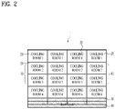
- FIG. 2 is a simplified view of a front face of a shared refrigerator
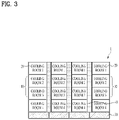
- FIG. 3 is a simplified view of a rear face of a shared refrigerator.
- three units arranged in the vertical direction form one module, and one unit is stacked on top of the module.
- the storage chamber is formed in 4 rows and 4 columns.
- one shared refrigerator is formed by coupling a plurality of sub-elements (the units, the modules, and the machine rooms) to each other. Therefore, it may be important to ensure integrity of the appearance.
- a base cover 40 for covering a front face of the bottom of the shared refrigerator 1 may be disposed.
- the base cover 40 may be attached to front faces of the machine rooms. That is, the base cover 40 may be disposed separately from the machine room and may be coupled to the machine room from at the front face of the machine room.
- the base cover 40 may be disposed to cover all of the plurality of machine rooms 30 arranged in the horizontal direction. Therefore, a gap between one machine room and another machine room is not exposed to the outside by the base cover 40.
- a screen or a decor 50 may be disposed.
- the decor 50 may be located on a rear face of the shared refrigerator 1. Specifically, the decor that is vertically long covers the gap in the horizontal direction between one unit and the other unit. Accordingly, the integrity of the appearance may be secured at the front face of the shared refrigerator 1.
- a separate fastening portion may be disposed.
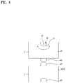
- FIG. 4 schematically shows a coupled state of units, modules, and machine rooms, which are sub-elements.
- Each of the module 10, the unit 20, and the machine room 30 may have a cabinet forming an appearance thereof.
- FIG. 4 shows coupling between the cabinet 21 of one unit 20 and the cabinet 21 of another unit 20 as an example.
- a coupling portion 60 for coupling with other sub-elements may be formed on at least one of a top face, a bottom face, and side faces of the cabinet 21.
- the coupling portion may be pivotable with respect to the cabinet 21. Because of such pivoting, the coupling portion may be located inside the cabinet 21 or outside the cabinet.
- the coupling portion 60 of one unit 20 may be mated with the coupling portion 60 of the adjacent unit 20.
- the coupling portion 60 may include a protrusion 61 that may protrude out of the cabinet and an accommodating portion 62 that may accommodate therein an adjacent protrusion 61.
- the protrusion and the accommodating portion may be formed at the same time.
- the coupling portion 60 of one unit When the two units are coupled to each other, the coupling portion 60 of one unit may be positioned such that the protrusion 61 thereof faces the interior of the cabinet 21. In this regard, the entire coupling portion 60 may be located inside the cabinet.
- the coupling portion 60 of the other unit may be positioned such that the protrusion 61 thereof protrudes outwardly of the cabinet 21.
- the protrusion 61 protruding out of the cabinet may be inserted into the accommodating portion 62 of the adjacent unit.
- the gap between one unit and the other unit may be minimized through the mating of the coupling portion 60 and the coupling portion 60 thereof.
- the coupling portion 60 is not substantially exposed to the outside, the beautiful design may be implemented.
- the coupling portion 60 not only the physical coupling between the sub-elements through the coupling portion 60 is possible, but also electrical connection or control connection between the units may be possible. This means that the plurality of units may be controlled through one machine room.
- the coupling portions 60 may be disposed not only for the vertical coupling of the sub-elements, but also for the horizontal coupling of the sub-elements. When the two modules 10 are closely positioned in the horizontal direction, the coupling via the coupling portions 60 may be possible.
- the coupling via the coupling portions 60 between all adjacent sub-elements may not be required.
- one module 10 and another module 10 may be individually controlled through the respective machine rooms. Accordingly, only the coupling via the coupling portions 60 between one machine room and another machine room and coupling via the coupling portions 60 between the uppermost unit and the unit may be required.
- one module 10 may serve as a main controller, and other modules 10 may serve as sub-controllers.
- the main controller may control the sub-controllers and a display, and the main controller may also communicate with the user or the provider.
- the shared refrigerator 1 includes the individual cooling unit 10. Because frost is formed inside the storage chamber of the cooling unit, defrosting is required. As will be described later, in a case of direct cooling, there is a greater risk of frost forming on a wall face or a radiational cooling plate of the storage chamber. However, it is not easy to implement a separate defrosting system for each individual cooling unit 10. This is because, when the defrosting system is implemented individually, a capacity of the storage chamber in the cooling unit is inevitably reduced.
- FIG. 5 shows a concept of applying the defrosting system in the refrigerator module 10 in the shared refrigerator according to one embodiment of the present disclosure.
- a simplified view of the rear face of the refrigerator module is shown.
- An opening 72 may be defined in a bottom face of the storage chamber such that defrosting water is discharged out of the storage chamber.
- the opening 72 may be connected to a defrosting water line 70, and the defrosting water line 70 may extend through the bottom face of the cabinet 21 to extend through a top face of the cabinet 21 of the lower unit 20.
- each storage chamber may have only one opening 72 defined in the bottom face of the cabinet 21 thereof.
- Each of the remaining units 20 may have the openings 72 respectively defined in the top face and the bottom face of the cabinet 21 thereof.
- the defrosting water generated in each storage chamber may be introduced into the machine room 40 through the defrosting water line 70.
- the machine room 40 may have a defrosting water container 71 for storing the defrosting water therein.
- the defrosting water line 70 is preferably disposed biased to a rear face of the module 10. This is to prevent reduction in a storage space. In addition, it is preferable that the defrosting water line is disposed biased to the left or right. This is to use the storage space efficiently.
- the defrosting is preferably performed in an entirety of one module 10. That is, start and end of the defrosting may be performed identically in one module.
- each storage chamber will be equipped with a temperature sensor for controlling a temperature of the storage chamber. Because this is a very basic component in the refrigerator, separate illustration and description thereof will be omitted.
- a defrosting time point may be determined by considering a temperature sensed via the temperature sensor, an operating time of a compressor, an opening time of the door, and the like. In addition, the defrosting may be carried out at the same time for the modules 10. When the temperature sensors of all of the storage chambers sense a temperature equal to or higher than a certain temperature, the defrosting may be terminated.
- the defrosting may be performed as opposed to cooling. That is, the defrosting may be performed by increasing the temperature of the storage chamber by stopping the operation of the compressor. When a fan is disposed in the storage chamber, natural defrosting may be possible by driving only the fan. In addition, forced defrosting may be performed through a separate defrosting heater. The defrosting heater may be coupled to the radiational cooling plate to perform the defrosting.
- each unit 20 in the refrigerator module 10 having the storage chamber that is individually opened and closed by the door has the built-in defrosting water line 70 or the opening 72 defined therein for the connection with the defrosting water line 70.
- the defrosting water line may be equipped with the defrosting water container and a trap.
- the defrosting water container and the trap may have a structure that is normally closed and is opened when a weight exceeds a certain weight. That is, the defrosting water generated in each storage chamber may be concentrated on the bottom face of the storage chamber, so that the defrosting water container and the trap may be normally closed, but may be opened when the weight of the defrosting water exceeds the certain weight. Because shapes and structures of the defrosting water container and the trap are general matters, illustration and description thereof will be omitted.
- simultaneous defrosting may be possible for the modules.
- the defrosting system may be applied as described above.
- a defrosting water spout, a heater, or the like may be added.
- the defrosting water spout, the heater, or the like may be added.
- an inclined defrosting water spout 73 may be located on the bottom face of the storage chamber.
- the defrosting water spout 73 may be installed on a bottom face of a rear wall of the storage chamber.
- the lowermost portion of the defrosting water spout 73 may be connected to the opening 72. Accordingly, the defrosting water may be discharged to the outside through the defrosting water spout 73, the opening 72, and the defrosting water line 70.
- the defrosting water may freeze.
- an anti-freezing heater may be mounted near the defrosting water spout 73.
- the defrosting heater 73 may be disposed.
- the defrosting heater 73 may be mounted inside the rear wall of the storage chamber. That is, the defrosting heater may be disposed between the rear wall of the storage chamber and the cabinet.
- the defrosting heater 73 may be disposed individually for each unit.
- a defrosting sensor for determining the start and the end of the defrosting may be disposed near the defrosting heater 73.
- a temperature of a storage chamber that does not require the defrosting may be unnecessarily raised. Therefore, it is possible to perform the defrosting only for a storage chamber that requires the defrosting through the defrosting sensor.
- the heater for the defrosting may not be disposed individually for each unit, but may be formed throughout the module. This may be referred to as a module defrosting heater 75.
- the module defrosting heater 75 When the module defrosting heater 75 is driven, the defrosting for the entire module may be performed.
- the fan inside the specific storage chamber may be driven primarily. In this case, only the necessary storage chamber may be defrosted naturally. In one example, when the fan is not disposed inside the storage chamber, the primary defrosting may be omitted.
- the defrosting heater 74 may be operated to perform the defrosting secondarily. In one example, when the defrosting heater 74 is not disposed, the secondary defrosting may be omitted.
- a temperature rise slope of the defrosting sensor may be determined, so that, when additional defrosting is required, the module defrosting heater 75 may be driven tertiarily to perform overall defrosting. In another example, when the module defrosting heater 75 is not disposed, the tertiary defrosting may be omitted.
- the secondary or tertiary defrosting may be performed, it is possible to more effectively perform the defrosting of the plurality of storage chambers.
- the shared refrigerator according to the present embodiment may be referred to as a refrigerator in which the storage chambers are respectively used by the separate users. Therefore, it is preferable that the storage chambers do not share cold air or odors. In other words, it is necessary to apply separate cooling systems for the respective storage chambers. However, in this case, a plurality of flow path structures and a plurality of machine rooms need to be installed. Therefore, modularization is not easy.
- the shared refrigerator may perform individual cooling for each storage chamber by applying a cold air circulating module or a cold air circulating flow path.
- FIG. 7 briefly shows a side face of a shared refrigerator to which a cold air circulation module is applied
- FIG. 8 shows a state in which a cold air circulation module is separated from a shared refrigerator.
- the units and the storage chambers inside the respective units are partitioned from each other. That is, the units and the storage chambers inside the units do not share the cold air.
- a radiational cooling plate 26 may be disposed on the rear wall of each unit 20. As a temperature of the radiational cooling plate decreases, an interior temperature of the storage chamber may decrease by radiation cooling. That is, the radiational cooling plate itself is the rear wall of the storage chamber, so that the radiational cooling plate may be referred to as a portion of the storage chamber.
- the cold air circulating module may be mounted in the rear of the radiational cooling plates 26 of the units 20. This may be referred to as a cold air circulating flow path 90. After the cold air generated in the machine room 40 flows to an upper portion of the cold air circulating flow path 90, the cold air may descend and be introduced into the machine room 40. The descending cold air exchanges heat with the radiational cooling plate 26 to cool the radiational cooling plate.
- a rear face heat insulating portion 80 may be disposed in the rear of the radiational cooling plate 26. Therefore, the circulated cold air may cool the radiational cooling plate 26 very efficiently.
- the cold air circulated in the cold air circulating flow path 90 does not flow into the storage chamber. Therefore, the independent cooling for each storage chamber is possible, and the cold air and the odor of the respective storage chambers do not mix with each other.
- a plurality of radiational cooling plates 26 may be installed in the storage chambers.
- a plurality of heat transfer fins may be formed on the radiational cooling plate, and the heat transfer fin may have various shapes such as a square, a triangular, or a circular shape.
- the radiational cooling plate may be installed separately from or integrally with the cold air circulating flow path 90.
- FIG. 8 shows a structure in which the radiational cooling plate 25 and the cold air circulating flow path 90 are integrally mounted in the module 10.
- an insertion hole 91 into which the radiational cooling plate and the cold air circulating flow path are inserted may be defined at a rear portion of the cabinet of the unit 20.
- the insertion hole 91 may be defined in each of the bottom face and the top face of the cabinet of each of the units. However, the insertion hole may be defined only in the bottom face of the cabinet of the uppermost unit. In another example, the uppermost unit may be the same as the other units. In this case, a separate stopper or cover for opening and closing the insertion hole defined in the top face may be mounted. Accordingly, manufacturing is facilitated by manufacturing the units to have basically the same structure.
- Each storage chamber may have a fan 26 to increase a cooling efficiency. However, when an internal space of the storage chamber is relatively small, the fan 26 may be omitted.
- a capacity of the storage chamber in the unit 20 of the module 10 is inevitably reduced due to the radiational cooling plate and the cold air circulating flow path. Accordingly, a single unit may be disposed independently of the module 10. Such single unit may use a cooling scheme different from that of the unit in the module 10.
- the uppermost unit shown in FIG. 9 may be cooled via a thermoelectric module 29.
- a small refrigerator using the thermoelectric module 29 is disclosed in Korean Patent (Application No. 10-2017-0035608 ) applied by the present applicant.
- thermoelectric module 29 may be applied to a cooling unit having a premium cooling compartment with low noise.
- the thermoelectric module 29 forms a rear wall of a refrigerating compartment.
- the thermoelectric module 29 may include a thermoelectric element, and a cooling sink 27 may be disposed in front of the thermoelectric element and a heat sink 28 may be disposed in the rear of the thermoelectric element. That is, the thermoelectric element is divided into a low temperature portion and a high temperature portion based on its own characteristics. The cooling may be performed by a temperature difference between the low temperature portion and the high temperature portion.
- the cooling sink 27 formed in the low temperature portion forms the rear wall of the storage chamber to cool the storage chamber.
- the heat sink 28 formed in the high temperature portion may be exposed to the outside to dissipate the heat through natural convection.
- thermoelectric module 29 the cooling scheme to which the thermoelectric module 29 is applied is independently applied to each unit. Therefore, there is no mixing of cold air between one storage chamber and another storage chamber. Therefore, one unit may be applied as the premium cooling compartment, which may be a unit that is easily added to an existing module.
- thermoelectric module it may be possible to construct said one module 10 with units to which such thermoelectric module is applied.
- the shared refrigerator may perform the individual cooling for each storage chamber by applying a refrigerant pipe module or a refrigerant pipe flow path.
- FIG. 10 briefly shows a side face of a shared refrigerator to which a cold air circulating module is applied.
- the units and the storage chambers inside the respective units are partitioned from each other. That is, the units and the storage chambers inside the units do not share the cold air.
- the radiational cooling plate 26 may be disposed on the rear wall of each unit 20. As the temperature of the radiational cooling plate decreases, the interior temperature of the storage chamber may decrease by the radiation cooling. That is, the radiational cooling plate itself is the rear wall of the storage chamber, so that the radiational cooling plate may be referred to as the portion of the storage chamber.
- the refrigerant pipe module may be mounted in the rear of the radiational cooling plates 26 of the units 20. This may be referred to as a refrigerant pipe flow path 95. After a refrigerant compressed in the machine room 40 cools the radiational cooling plate while flowing through a refrigerant pipe, the refrigerant may be introduced into the machine room 40.
- the rear face heat insulating portion 80 may be disposed in the rear of the radiational cooling plate 26. Therefore, the circulated refrigerant may cool the radiational cooling plate 26 very efficiently.
- the refrigerant circulated in the refrigerant pipe flow path 95 directly cools the radiational cooling plate in contact with the radiational cooling plate. Therefore, the independent cooling for each storage chamber is possible, and the cold air and the odor of the respective storage chambers do not mix with each other.
- the plurality of radiational cooling plates 26 may be installed in the storage chambers.
- the plurality of heat transfer fins may be formed on the radiational cooling plate, and the heat transfer fin may have various shapes such as the square, the triangular, or the circular shape.
- the radiational cooling plate may be installed separately from or integrally with the refrigerant pipe flow path 95.
- the refrigerant pipe may be integrally formed on the radiational cooling plate.
- the radiational cooling plate and the refrigerant pipe may be integrally formed by a roll bond method.
- Such example in which the radiational cooling plate and the refrigerant pipe are integrally formed may be similar to an evaporator forming a freezer compartment of the small refrigerator.
- the radiational cooling plate and the refrigerant pipe flow path may be integrally mounted in the module 10. That is, the insertion hole 91 into which the radiational cooling plate and the refrigerant pipe flow path are inserted may be defined at the rear portion of the cabinet of the unit 20.
- the single unit to which the thermoelectric module 29 is applied as described above may also be located on top of the module 10 in the present embodiment.
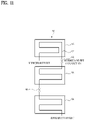
- FIGS. 11 to 13 show plates 96 and refrigerant pipes 97 integrally formed on the plates 96.
- the plate 96 may be formed independently for each unit. Alternatively, some plates may be formed integrally and the remaining plates may be formed independently, or the entire plates may be formed integrally. That is, as the number of plates 96 for respectively covering the storage chambers of the same number increases, the number of connecting portions 98 for connecting the refrigerant pipes between two plates inevitably increases.
- FIG. 11 shows a case in which there are two refrigerant pipe connecting portions
- FIG. 12 shows a case in which there is one refrigerant pipe connecting portion
- FIG. 13 shows a case in which there is no refrigerant pipe connecting portion.
- One inlet through which the refrigerant flows into the plate 96 and one outlet through which the refrigerant is discharged should be formed in all of the cases in FIGS. 11 to 13 .
- the refrigerant pipe for connecting the inlet and the outlet to each other may be embedded in the rear face heat insulating portion 80 independently of the plate 96.
- the plate 96 may be a component that is in close contact with the radiational cooling plate 25 to cool the radiational cooling plate.
- the plate 96 may be the radiational cooling plate itself.
- the connecting portion of the refrigerant pipes, the inlet, the outlet, and the refrigerant pipe connected to the inlet and the outlet described above may all be embedded in the rear face heat insulating portion 80.
- all of such components may be formed into a single cartridge and inserted and mounted in the module. Thereafter, the rear face heat insulating portion may be formed through foaming.
Landscapes
- Engineering & Computer Science (AREA)
- Chemical & Material Sciences (AREA)
- Combustion & Propulsion (AREA)
- Physics & Mathematics (AREA)
- Mechanical Engineering (AREA)
- Thermal Sciences (AREA)
- General Engineering & Computer Science (AREA)
- Devices That Are Associated With Refrigeration Equipment (AREA)
- Cold Air Circulating Systems And Constructional Details In Refrigerators (AREA)
Applications Claiming Priority (2)
| Application Number | Priority Date | Filing Date | Title |
|---|---|---|---|
| KR1020190155136A KR20210066195A (ko) | 2019-11-28 | 2019-11-28 | 복수 개의 저장실 갖는 모듈을 포함하는 냉장고 |
| PCT/KR2020/012838 WO2021107368A1 (ko) | 2019-11-28 | 2020-09-23 | 복수 개의 저장실 갖는 모듈을 포함하는 냉장고 |
Publications (2)
| Publication Number | Publication Date |
|---|---|
| EP4067784A1 true EP4067784A1 (de) | 2022-10-05 |
| EP4067784A4 EP4067784A4 (de) | 2024-02-28 |
Family
ID=76130316
Family Applications (1)
| Application Number | Title | Priority Date | Filing Date |
|---|---|---|---|
| EP20894808.3A Pending EP4067784A4 (de) | 2019-11-28 | 2020-09-23 | Kühlschrank mit modul mit mehreren speicherkammern |
Country Status (4)
| Country | Link |
|---|---|
| US (1) | US12196477B2 (de) |
| EP (1) | EP4067784A4 (de) |
| KR (1) | KR20210066195A (de) |
| WO (1) | WO2021107368A1 (de) |
Family Cites Families (12)
| Publication number | Priority date | Publication date | Assignee | Title |
|---|---|---|---|---|
| US3089313A (en) * | 1961-09-05 | 1963-05-14 | Thomas J Fix | Refrigeration locker assembly |
| JPH09329382A (ja) * | 1996-03-28 | 1997-12-22 | Sanko:Kk | 宅配物保管用ボックス装置 |
| US5921095A (en) * | 1996-12-11 | 1999-07-13 | Lg Electronics Inc. | Expandable type refrigerator |
| DE19957530C2 (de) * | 1999-11-30 | 2003-11-27 | Eisfink Max Maier Gmbh & Co Kg | Übergabeeinrichtung für von Kunden vorbestellte Waren in Kaufhäusern, Supermärkten od.dgl. |
| JP2004101028A (ja) | 2002-09-06 | 2004-04-02 | Matsushita Refrig Co Ltd | 冷蔵庫 |
| JP2010043750A (ja) | 2008-08-08 | 2010-02-25 | Sharp Corp | 冷凍冷蔵庫 |
| US20150241108A1 (en) | 2013-12-04 | 2015-08-27 | Pedro Miguel Fernandez Maldonado | Minimum cavetto module portable refrigerated cabinet with one free cold passage |
| GB2552084B (en) * | 2014-01-29 | 2018-08-01 | Illinois Tool Works | A locker system |
| FI20145487L (fi) * | 2014-05-28 | 2015-11-29 | Norpe Oy | Jakelulaatikkojärjestelmä ja menetelmä päivittäistarviketuotteiden toimittamiseksi |
| KR20160023459A (ko) | 2014-08-22 | 2016-03-03 | 주식회사 대유위니아 | 냉장고 |
| KR20170035608A (ko) | 2015-09-23 | 2017-03-31 | 삼성전자주식회사 | 화상 통화 시스템, 영상표시장치, 영상표시장치의 구동 방법, 실감 영상 생성 방법 및 컴퓨터 판독가능 기록매체 |
| KR102327848B1 (ko) | 2017-05-18 | 2021-11-18 | 삼성전자주식회사 | 냉장고 및 냉장고의 음식 관리방법 |
-
2019
- 2019-11-28 KR KR1020190155136A patent/KR20210066195A/ko active Pending
-
2020
- 2020-09-23 EP EP20894808.3A patent/EP4067784A4/de active Pending
- 2020-09-23 WO PCT/KR2020/012838 patent/WO2021107368A1/ko not_active Ceased
- 2020-09-23 US US17/779,451 patent/US12196477B2/en active Active
Also Published As
| Publication number | Publication date |
|---|---|
| US20220404088A1 (en) | 2022-12-22 |
| US12196477B2 (en) | 2025-01-14 |
| KR20210066195A (ko) | 2021-06-07 |
| EP4067784A4 (de) | 2024-02-28 |
| WO2021107368A1 (ko) | 2021-06-03 |
Similar Documents
| Publication | Publication Date | Title |
|---|---|---|
| US10514195B2 (en) | Refrigerator | |
| CN102906518B (zh) | 制冷柜 | |
| EP3845842B1 (de) | Eingangskühlschrank und aufbewahrungssystem für einen hauseingang damit | |
| CN108626932A (zh) | 冰箱 | |
| EP3699532B1 (de) | Eintrittskühlschrank | |
| US20180274828A1 (en) | On-door ice maker cooling | |
| US12203692B2 (en) | Refrigerator comprising module having multiple storage chambers | |
| EP3699529B1 (de) | Eintrittskühlschrank | |
| EP3845843B1 (de) | Aufbewahrungssystem für den hauseingang | |
| US12196477B2 (en) | Refrigerator including module having plurality of storage chambers | |
| EP3699524B1 (de) | Eintrittskühlschrank | |
| EP3699528B1 (de) | Eintrittskühlschrank | |
| EP3699530A1 (de) | Eintrittskühlschrank | |
| CN214223505U (zh) | 储物设备 | |
| EP3845846B1 (de) | Eingangskühlschrank und steuerungsverfahren dafür | |
| KR100695539B1 (ko) | 와인 냉장고 | |
| CN101603757A (zh) | 具有透明门和不透明门的制冷设备 | |
| KR102858746B1 (ko) | 현관용 냉장고 | |
| JPH11337246A (ja) | 冷凍冷蔵庫 | |
| JP2000028247A (ja) | 貯蔵庫 | |
| KR19990037787U (ko) | 캔음료 자동판매기의 고내 구획벽 |
Legal Events
| Date | Code | Title | Description |
|---|---|---|---|
| STAA | Information on the status of an ep patent application or granted ep patent |
Free format text: STATUS: THE INTERNATIONAL PUBLICATION HAS BEEN MADE |
|
| PUAI | Public reference made under article 153(3) epc to a published international application that has entered the european phase |
Free format text: ORIGINAL CODE: 0009012 |
|
| STAA | Information on the status of an ep patent application or granted ep patent |
Free format text: STATUS: REQUEST FOR EXAMINATION WAS MADE |
|
| 17P | Request for examination filed |
Effective date: 20220623 |
|
| AK | Designated contracting states |
Kind code of ref document: A1 Designated state(s): AL AT BE BG CH CY CZ DE DK EE ES FI FR GB GR HR HU IE IS IT LI LT LU LV MC MK MT NL NO PL PT RO RS SE SI SK SM TR |
|
| DAV | Request for validation of the european patent (deleted) | ||
| DAX | Request for extension of the european patent (deleted) | ||
| REG | Reference to a national code |
Ref country code: DE Ref legal event code: R079 Free format text: PREVIOUS MAIN CLASS: F25D0019020000 Ipc: F25D0019040000 |
|
| RIC1 | Information provided on ipc code assigned before grant |
Ipc: F25D 13/02 20060101ALI20231030BHEP Ipc: F25D 19/04 20060101AFI20231030BHEP |
|
| A4 | Supplementary search report drawn up and despatched |
Effective date: 20240129 |
|
| RIC1 | Information provided on ipc code assigned before grant |
Ipc: F25D 13/02 20060101ALI20240123BHEP Ipc: F25D 19/04 20060101AFI20240123BHEP |
|
| STAA | Information on the status of an ep patent application or granted ep patent |
Free format text: STATUS: EXAMINATION IS IN PROGRESS |
|
| 17Q | First examination report despatched |
Effective date: 20250519 |