EP4067676A1 - Befestigungsvorrichtung zur befestigung eines elements einer befestigungsmittels, element eines befestigungsmittels und druckknopf - Google Patents
Befestigungsvorrichtung zur befestigung eines elements einer befestigungsmittels, element eines befestigungsmittels und druckknopf Download PDFInfo
- Publication number
- EP4067676A1 EP4067676A1 EP21166233.3A EP21166233A EP4067676A1 EP 4067676 A1 EP4067676 A1 EP 4067676A1 EP 21166233 A EP21166233 A EP 21166233A EP 4067676 A1 EP4067676 A1 EP 4067676A1
- Authority
- EP
- European Patent Office
- Prior art keywords
- column
- protrusions
- fixture
- fastener
- fixture according
- Prior art date
- Legal status (The legal status is an assumption and is not a legal conclusion. Google has not performed a legal analysis and makes no representation as to the accuracy of the status listed.)
- Withdrawn
Links
- 239000007787 solid Substances 0.000 claims abstract description 8
- 239000000463 material Substances 0.000 claims description 4
- 229910001297 Zn alloy Inorganic materials 0.000 claims description 3
- 239000002184 metal Substances 0.000 claims description 2
- 229910052751 metal Inorganic materials 0.000 claims description 2
- 239000002991 molded plastic Substances 0.000 claims description 2
- 239000004744 fabric Substances 0.000 description 3
- NJPPVKZQTLUDBO-UHFFFAOYSA-N novaluron Chemical compound C1=C(Cl)C(OC(F)(F)C(OC(F)(F)F)F)=CC=C1NC(=O)NC(=O)C1=C(F)C=CC=C1F NJPPVKZQTLUDBO-UHFFFAOYSA-N 0.000 description 2
- 238000005452 bending Methods 0.000 description 1
- 238000005336 cracking Methods 0.000 description 1
- 230000002708 enhancing effect Effects 0.000 description 1
- 238000004519 manufacturing process Methods 0.000 description 1
- 230000013011 mating Effects 0.000 description 1
- 239000007769 metal material Substances 0.000 description 1
- 239000004033 plastic Substances 0.000 description 1
- 230000000717 retained effect Effects 0.000 description 1
Images


Classifications
-
- F—MECHANICAL ENGINEERING; LIGHTING; HEATING; WEAPONS; BLASTING
- F16—ENGINEERING ELEMENTS AND UNITS; GENERAL MEASURES FOR PRODUCING AND MAINTAINING EFFECTIVE FUNCTIONING OF MACHINES OR INSTALLATIONS; THERMAL INSULATION IN GENERAL
- F16B—DEVICES FOR FASTENING OR SECURING CONSTRUCTIONAL ELEMENTS OR MACHINE PARTS TOGETHER, e.g. NAILS, BOLTS, CIRCLIPS, CLAMPS, CLIPS OR WEDGES; JOINTS OR JOINTING
- F16B21/00—Means for preventing relative axial movement of a pin, spigot, shaft or the like and a member surrounding it; Stud-and-socket releasable fastenings
- F16B21/06—Releasable fastening devices with snap-action
- F16B21/07—Releasable fastening devices with snap-action in which the socket has a resilient part
- F16B21/073—Releasable fastening devices with snap-action in which the socket has a resilient part the socket having a resilient part on its inside
-
- A—HUMAN NECESSITIES
- A44—HABERDASHERY; JEWELLERY
- A44B—BUTTONS, PINS, BUCKLES, SLIDE FASTENERS, OR THE LIKE
- A44B17/00—Press-button or snap fasteners
- A44B17/0023—Press-button fasteners in which the elastic retaining action is obtained by the own elasticity of the material constituting the fastener
-
- A—HUMAN NECESSITIES
- A44—HABERDASHERY; JEWELLERY
- A44B—BUTTONS, PINS, BUCKLES, SLIDE FASTENERS, OR THE LIKE
- A44B17/00—Press-button or snap fasteners
- A44B17/0052—Press-button fasteners consisting of four parts
Definitions
- the invention refers to a fixture for fixing a member of a fastener, particularly of a snap fastener, to a support, comprising a base and 2 or more protrusions, preferably 2 to 10, more preferably 2 to 6.
- Said fastener member is, e.g. a female member of a snap fastener fixed to a fabric by said fixture and configured to cooperate with a mating male member of the snap fastener.
- Fixtures as described above are known, e.g. from EP 3 228 206 A1 with protrusions in the form of shanks.
- DE 38 14 497 A1 describes a fixture with a single protrusion in the form of a sleeve or pipe.
- a similar solution is known from EP 2 524 612 A1 , but with hollows or grooves at the distal end of the sleeve or pipe.
- the above object is achieved by a solid column protruding from the base, wherein the protrusions are protruding from a distal end of the column.
- Distal refers to a position furthest the plane of the base and proximal refers to a position farthest from the distal position in a direction perpendicular towards the plane of the base.
- Height refers to a distance measured in the direction proximal-distal that is a distance perpendicular to the plane of the base; the same distance when measured in the distal-proximal direction is referred to as 'depth'.
- Outer refers to a direction away from the central axis of the member and 'inner' refers to its opposite.
- Width refers to a distance between two points on the member parallel to a plane perpendicular to the column which may be obtained by a straight line or an arc.
- the column according to the invention is a structure configured and positioned to extend into or through the support or a part of the fastener member or both of them in the proximal-distal direction, when the fixture is in a condition fixing the fastener member to the support.
- the column according to the invention can be looked at as a pedestal on which the 2 or more protrusions are standing.
- the column protrudes from the base preferably from its central axis.
- the column and/or at least one of the protrusions is /are perpendicular to the plane of the base.
- the total cross-sectional area at the proximal ends of all the protrusions protruding from the column is smaller than the cross-sectional area of the column at the distal end thereof. This particularly facilitates the application of the fixture, particularly by facilitating the bending of the protrusions.
- the protrusions are equidistant from each other.
- a portion of the distal end of the column between two adjacent protrusions is radial, and more preferably concave.
- the protrusions extend immediately from the solid column, however in some embodiments, an annular portion may be comprised between the distal end of the solid column and the proximal portion of the protrusions. Preferably the annular portion extends around the entire periphery of the column. Such a portion may save on material. This saving may be obtained because height from the proximal portion of the column to the distal surface of a protrusion must be greater than a support and so may be particularly convenient for deeper supports.
- the inner-outer dimensions of the protrusions and of the annular portion need not be the same.
- the protrusions extend from the periphery of the distal end of the column.
- the periphery formed by the outer surfaces of the protrusions and the spaces therebetween is cylindrical.
- the base has a recess adjacent to the column.
- This recess can take in parts of the above-mentioned support and/or of the above-mentioned fastener member.
- the cross-sectional contour of the recess might be rounded.
- the column is preferably higher than the recess, but need not be.
- the recess is in the form of a closed loop, e.g. ring-shaped and circulates the column.
- the fixture is invariant to the orientation of said fastener member in the circumferential direction.
- the depth of the recess is smaller than the length of at least one of the protrusions. Namely, the protrusions have to pierce said support, e.g. a fabric, whereas the recess just holds a portion of it.
- the respective height or depth of each of the column, the protrusions and the annular portion is consistent but variations are also possible.
- the column is cylindrical at its distal end. This helps to prevent cracking.
- the top surface of at least one of the protrusions is flat. This ensures that the part of the fastener member within which the protrusion is retained in order to fix the fastener member to the support is not damaged or deformed by the respective protrusion.
- top surface of a protrusion may comprise a portion of an annulus, with an outer circumference greater than an inner circumference and the width taking the form of an arc.
- the outer circumference arc has the same radius as the column and the radius of the inner circumference arc is smaller.
- the width of at least one of the protrusions at the outer circumference thereof may be greater than at the inner circumference thereof. This enhances the contact with the cooperating part of the fastener member and thus provides stability.
- the outer surfaces of at least one of the protrusions and the column are flush with one another at the proximal end of said protrusion and the distal end of the column, respectively.
- the column protrudes beyond the total contour of the base in the distal direction.
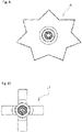
- the contour of the base can have any shape according to the invention. Preferably, however, said contour is circular or in the shape of a star or a cross.
- the base, the column and the protrusions are integrally formed. This simplifies the manufacturing process.
- the base, the column and/or the protrusions comprise(s) metal, in particular a zinc alloy, or comprises injection-molded plastic material.
- the invention refers to a member of a fastener, particularly of a snap fastener, in combination with a fixture as described above.
- the invention refers to a snap fastener comprising such a member.
- Fixture 1 shown in Figs. 1 to 3 is an integrally formed part made of a zinc alloy and comprises a base 10, six protrusions, one of which having the reference numeral 12, and a solid column 14. As is particularly to be taken from Fig. 3 , protrusions 12 protrude from the distal end 16 of column 14.
- protrusions 12 are positioned distant from one another with some room between them.
- Column 14 is surrounded by a recess 18. According to Fig. 3 , the cross-sectional contour of recess 18 is rounded. This facilitates the mounting of the fixture to other components.
- the depth D of recess 18 is smaller than the length L of protrusions 12. Particularly in the region of its distal end 16, column 14 is cylindrical.
- At least one top surface 20 of protrusions 12 is flat.
- Said top surface has trapezoidal shape because the width of protrusions 12 at the outer circumference of the column 14 is greater than at the inner circumference of said pedestal, cf. particularly Fig. 1 .
- the protrusions are of similar (trapezoidal) design but any appropriate combination of designs may be selected.
- Fig. 4 shows a female member 22 of a snap fastener attached to a support 24 by fixture 1 according to Figs. 1 to 3 .
- fixture 10 and female member 22 are held coaxially with another with support 24 therebetween, and upper and lower dies (not shown) are used to make protrusions 12 to pierce support 24 and to bend from the status shown in Fig. 3 into the status shown in Fig. 4 .
- female member 22 and support 24 are moved in a direction toward fixture 10, for example downwards, so that protrusions 12 pierce support 24 and reach into the lower part of female member 22. Simultaneously, column 14 enters into the pierced hole of support 24 and even beyond into female member 22.
- a protrusion is substantially perpendicular the plane of the base.
- force is applied to the base of the fixture such that the protrusion and preferably a portion of the column comprising the distal end 16 of the column enters and penetrates the support. Less force is required when a protrusion is perpendicular. Because the column is substantially solid, when attaching force is applied to the base, this does not crack or otherwise deform the column. In a similar manner, it is preferable that the column protrudes in a direction substantially perpendicular to the plane of the base that is to say, parallel to the intended direction of the attaching force.
- Fig. 5 shows fixture 1 holding a female member 22 differing in some respects from the female member 22 shown in Fig. 4 .
- a part of female member 22 shown in Fig. 5 is made of plastic, whereas female member 22 shown in Fig. 4 is completely made of metal material.
- Fig. 6 shows fixture 1 for fixing female member 22 to support 24 as well as male member 28 to be held by fixture 30 on support 32.
- Fixture 30 for male member 28 may be laid out according to the invention, e.g. like fixture 1 for female member 22, while this is not the case in the embodiment shown in Fig. 6 .
- Fig. 7 shows parts similar to the parts shown in Fig. 6 , but in the mounted status. What is to be noted in this respect is that Fig. 7 is a schematical view.
- Fig. 8 shows a situation similar to Fig. 7 , but as a sectional view.
- the outer contour of base 10 of fixture 1 can have various shapes apart from the circular, particularly the shapes of a star or a cross. Contrary thereto, column 14 and/or recess 18 have preferably more or less circular shapes in order to be invariant to the orientation of the fastener member to be held in the circumferential direction.
Landscapes
- Engineering & Computer Science (AREA)
- General Engineering & Computer Science (AREA)
- Mechanical Engineering (AREA)
- Insertion Pins And Rivets (AREA)
Priority Applications (1)
| Application Number | Priority Date | Filing Date | Title |
|---|---|---|---|
| EP21166233.3A EP4067676A1 (de) | 2021-03-31 | 2021-03-31 | Befestigungsvorrichtung zur befestigung eines elements einer befestigungsmittels, element eines befestigungsmittels und druckknopf |
Applications Claiming Priority (1)
| Application Number | Priority Date | Filing Date | Title |
|---|---|---|---|
| EP21166233.3A EP4067676A1 (de) | 2021-03-31 | 2021-03-31 | Befestigungsvorrichtung zur befestigung eines elements einer befestigungsmittels, element eines befestigungsmittels und druckknopf |
Publications (1)
| Publication Number | Publication Date |
|---|---|
| EP4067676A1 true EP4067676A1 (de) | 2022-10-05 |
Family
ID=75339505
Family Applications (1)
| Application Number | Title | Priority Date | Filing Date |
|---|---|---|---|
| EP21166233.3A Withdrawn EP4067676A1 (de) | 2021-03-31 | 2021-03-31 | Befestigungsvorrichtung zur befestigung eines elements einer befestigungsmittels, element eines befestigungsmittels und druckknopf |
Country Status (1)
| Country | Link |
|---|---|
| EP (1) | EP4067676A1 (de) |
Citations (7)
| Publication number | Priority date | Publication date | Assignee | Title |
|---|---|---|---|---|
| US3979802A (en) * | 1974-03-21 | 1976-09-14 | Firma Schaeffer-Homberg Gmbh | Snap fastener |
| GB2029888B (en) | 1978-08-25 | 1982-06-16 | Scovill Japan | Snapfastener element |
| DE3814497A1 (de) | 1988-04-29 | 1989-11-09 | Prym Werke William | Befestigungsglied fuer ein matrizenfoermiges druckknopf-federteil |
| EP2524612A1 (de) | 2010-01-13 | 2012-11-21 | YKK Corporation | Element zum befestigen eines knopfes und knopf |
| US20130152347A1 (en) * | 2008-02-29 | 2013-06-20 | Ykk Corporation | Male Snap Part |
| US20140137373A1 (en) * | 2012-11-16 | 2014-05-22 | Fimma S.P.A. | Pressure snap fastener with a bivalent closure |
| EP3228206A1 (de) | 2014-12-01 | 2017-10-11 | YKK Corporation | Obere struktur eines druckknopfaufnahmeteils, druckknopfaufnahmeteil und verfahren zur befestigung eines druckknopfaufnahmeteils an material |
-
2021
- 2021-03-31 EP EP21166233.3A patent/EP4067676A1/de not_active Withdrawn
Patent Citations (8)
| Publication number | Priority date | Publication date | Assignee | Title |
|---|---|---|---|---|
| US3979802A (en) * | 1974-03-21 | 1976-09-14 | Firma Schaeffer-Homberg Gmbh | Snap fastener |
| GB2029888B (en) | 1978-08-25 | 1982-06-16 | Scovill Japan | Snapfastener element |
| DE3814497A1 (de) | 1988-04-29 | 1989-11-09 | Prym Werke William | Befestigungsglied fuer ein matrizenfoermiges druckknopf-federteil |
| US20130152347A1 (en) * | 2008-02-29 | 2013-06-20 | Ykk Corporation | Male Snap Part |
| EP2524612A1 (de) | 2010-01-13 | 2012-11-21 | YKK Corporation | Element zum befestigen eines knopfes und knopf |
| US20140137373A1 (en) * | 2012-11-16 | 2014-05-22 | Fimma S.P.A. | Pressure snap fastener with a bivalent closure |
| EP3228206A1 (de) | 2014-12-01 | 2017-10-11 | YKK Corporation | Obere struktur eines druckknopfaufnahmeteils, druckknopfaufnahmeteil und verfahren zur befestigung eines druckknopfaufnahmeteils an material |
| US10568395B2 (en) * | 2014-12-01 | 2020-02-25 | Ykk Corporation | Upper structure of female snap button, female snap button and method of attaching female snap button to texture |
Similar Documents
| Publication | Publication Date | Title |
|---|---|---|
| EP3228206B1 (de) | Obere struktur eines druckknopfaufnahmeteils, druckknopfaufnahmeteil und verfahren zur befestigung eines druckknopfaufnahmeteils an material | |
| CA1187676A (en) | Snap fastener for use on garments | |
| US4156553A (en) | Contact for electrical connector | |
| KR850000877Y1 (ko) | 단추 | |
| CN110612039A (zh) | 按扣 | |
| KR850003010Y1 (ko) | 단추 | |
| US10278457B2 (en) | Female snap button | |
| CN107920633B (zh) | 按扣 | |
| KR0154265B1 (ko) | 고정구 | |
| EP4067676A1 (de) | Befestigungsvorrichtung zur befestigung eines elements einer befestigungsmittels, element eines befestigungsmittels und druckknopf | |
| US8522403B2 (en) | Button as well as button body and fixture for such a button | |
| US6601814B2 (en) | Rotatable hook mount for utility light | |
| JP4445920B2 (ja) | ボタン用キャップ、止め具およびボタン | |
| US4761863A (en) | Structure of snap | |
| US20160227890A1 (en) | Barb and cup jewelry link | |
| US7614125B2 (en) | Positive hold tube weld stud assembly | |
| EP3589876B1 (de) | Schnellverbinder | |
| EP1895082A2 (de) | Scharnier mit Befestigungsglied | |
| EP0216081B1 (de) | Deckelöse für Druckknopfverschluss | |
| JP7198372B2 (ja) | ボタン用取付具 | |
| CN220378653U (zh) | 紧固件和紧固件组件 | |
| JP6281112B2 (ja) | 固定具 | |
| JPS6237447Y2 (de) | ||
| CN214630422U (zh) | 防松脱的扣具 | |
| JP2004187916A (ja) | ハトメ |
Legal Events
| Date | Code | Title | Description |
|---|---|---|---|
| PUAI | Public reference made under article 153(3) epc to a published international application that has entered the european phase |
Free format text: ORIGINAL CODE: 0009012 |
|
| STAA | Information on the status of an ep patent application or granted ep patent |
Free format text: STATUS: REQUEST FOR EXAMINATION WAS MADE |
|
| 17P | Request for examination filed |
Effective date: 20210331 |
|
| AK | Designated contracting states |
Kind code of ref document: A1 Designated state(s): AL AT BE BG CH CY CZ DE DK EE ES FI FR GB GR HR HU IE IS IT LI LT LU LV MC MK MT NL NO PL PT RO RS SE SI SK SM TR |
|
| STAA | Information on the status of an ep patent application or granted ep patent |
Free format text: STATUS: THE APPLICATION IS DEEMED TO BE WITHDRAWN |
|
| 18D | Application deemed to be withdrawn |
Effective date: 20230406 |