EP4067262A1 - Traveling rail and article transport facility - Google Patents
Traveling rail and article transport facility Download PDFInfo
- Publication number
- EP4067262A1 EP4067262A1 EP20897241.4A EP20897241A EP4067262A1 EP 4067262 A1 EP4067262 A1 EP 4067262A1 EP 20897241 A EP20897241 A EP 20897241A EP 4067262 A1 EP4067262 A1 EP 4067262A1
- Authority
- EP
- European Patent Office
- Prior art keywords
- plate segment
- traveling
- width direction
- traveling path
- groove
- Prior art date
- Legal status (The legal status is an assumption and is not a legal conclusion. Google has not performed a legal analysis and makes no representation as to the accuracy of the status listed.)
- Pending
Links
Images




Classifications
-
- B—PERFORMING OPERATIONS; TRANSPORTING
- B61—RAILWAYS
- B61B—RAILWAY SYSTEMS; EQUIPMENT THEREFOR NOT OTHERWISE PROVIDED FOR
- B61B13/00—Other railway systems
- B61B13/12—Systems with propulsion devices between or alongside the rails, e.g. pneumatic systems
-
- B—PERFORMING OPERATIONS; TRANSPORTING
- B60—VEHICLES IN GENERAL
- B60M—POWER SUPPLY LINES, AND DEVICES ALONG RAILS, FOR ELECTRICALLY- PROPELLED VEHICLES
- B60M1/00—Power supply lines for contact with collector on vehicle
- B60M1/30—Power rails
-
- B—PERFORMING OPERATIONS; TRANSPORTING
- B60—VEHICLES IN GENERAL
- B60M—POWER SUPPLY LINES, AND DEVICES ALONG RAILS, FOR ELECTRICALLY- PROPELLED VEHICLES
- B60M1/00—Power supply lines for contact with collector on vehicle
- B60M1/30—Power rails
- B60M1/34—Power rails in slotted conduits
-
- B—PERFORMING OPERATIONS; TRANSPORTING
- B61—RAILWAYS
- B61B—RAILWAY SYSTEMS; EQUIPMENT THEREFOR NOT OTHERWISE PROVIDED FOR
- B61B13/00—Other railway systems
- B61B13/02—Rack railways
-
- B—PERFORMING OPERATIONS; TRANSPORTING
- B65—CONVEYING; PACKING; STORING; HANDLING THIN OR FILAMENTARY MATERIAL
- B65G—TRANSPORT OR STORAGE DEVICES, e.g. CONVEYORS FOR LOADING OR TIPPING, SHOP CONVEYOR SYSTEMS OR PNEUMATIC TUBE CONVEYORS
- B65G1/00—Storing articles, individually or in orderly arrangement, in warehouses or magazines
- B65G1/02—Storage devices
- B65G1/04—Storage devices mechanical
- B65G1/06—Storage devices mechanical with means for presenting articles for removal at predetermined position or level
- B65G1/065—Storage devices mechanical with means for presenting articles for removal at predetermined position or level with self propelled cars
-
- B—PERFORMING OPERATIONS; TRANSPORTING
- B65—CONVEYING; PACKING; STORING; HANDLING THIN OR FILAMENTARY MATERIAL
- B65G—TRANSPORT OR STORAGE DEVICES, e.g. CONVEYORS FOR LOADING OR TIPPING, SHOP CONVEYOR SYSTEMS OR PNEUMATIC TUBE CONVEYORS
- B65G1/00—Storing articles, individually or in orderly arrangement, in warehouses or magazines
- B65G1/02—Storage devices
- B65G1/04—Storage devices mechanical
- B65G1/0492—Storage devices mechanical with cars adapted to travel in storage aisles
Definitions
- the present invention relates to a traveling rail defining a traveling path for an article transport vehicle for transporting articles, and an article transport facility including such traveling rails.
- Patent Literature 1 Traveling rails are known as described in, for example, Japanese Unexamined Patent Application Publication No. 2013-224185 (Patent Literature 1). Reference signs and names in parentheses used hereafter in describing the background are the reference signs and names in the cited literature.
- a traveling rail described in Patent Literature 1 includes a rail unit (front beam 16a) installed to extend along a traveling path, and a power feeder (feeder line 8) for feeding power to a power receiver (collector 9) in an article transport vehicle (article transport cart 2) through contact with the article transport vehicle.
- the rail unit includes an upper plate segment having a traveling surface, a lower plate segment at a position in a downward direction from the upper plate segment, and an intermediate plate segment joining an edge of the upper plate segment in a first width direction and an edge of the lower plate segment in the first width direction.
- the power feeder is located in the space defined by the upper plate segment, the lower plate segment, and the intermediate plate segment.
- Patent Literature 1 Japanese Unexamined Patent Application Publication No. 2013-224185
- any friction dust produced upon contact of the power receiver with the power feeder can be received on the lower plate segment to reduce scattering of such friction dust out of the traveling rail.
- friction dust received on the lower plate segment in the rail unit described above accumulates on the lower plate segment in a dispersed manner. Removing such friction dust from the lower plate segment can take time and effort.
- traveling rails that allow easy removal of friction dust and an article transport facility including such traveling rails are awaited.
- a traveling rail defines a traveling path for an article transport vehicle for transporting an article.
- the traveling rail includes a rail unit extending in a traveling path direction in which the traveling path extends, and a power feeder that feeds power to a power receiver in the article transport vehicle through contact with the power receiver.
- the rail unit includes an upper plate segment being a plate extending continuously in the traveling path direction and extending in a width direction, a lower plate segment being a plate extending continuously in the traveling path direction and extending in the width direction, and being at a position in a downward direction from the upper plate segment, and an intermediate plate segment being a plate extending continuously in the traveling path direction and extending in a vertical direction, and joining an edge of the upper plate segment in a first width direction and an edge of the lower plate segment in the first width direction.
- the width direction is a direction orthogonal to the traveling path direction as viewed in the vertical direction.
- the width direction includes the first width direction and a second width direction opposite to each other.
- the power feeder is located in a space defined by the upper plate segment, the intermediate plate segment, and the lower plate segment in the rail unit and extends continuously in the traveling path direction.
- the upper plate segment includes a traveling surface facing in an upward direction to allow a wheel in the article transport vehicle to roll on the traveling surface.
- the lower plate segment includes a lower flat portion being a flat plate extending in the traveling path direction and the width direction, and a groove protruding in the downward direction from the lower flat portion and extending continuously in the traveling path direction.
- the structure including the power feeder located in the space defined by the upper plate segment, the intermediate plate segment, and the lower plate segment in the rail unit allows friction dust produced upon contact of the power receiver with the power feeder to be received on the lower plate segment in the rail unit. This structure thus reduces scattering of friction dust around.
- the lower plate segment includes the lower flat portion and the groove to facilitate friction dust received on the lower plate segment to accumulate in the groove. This structure thus reduces scattering of friction dust from the traveling rail and also allows easy removal of friction dust accumulating on the lower plate segment.
- An article transport facility includes a first traveling rail being the traveling rail according to the above aspect, a second traveling rail spaced apart from the first traveling rail in the second width direction, and wiring extending continuously in the traveling path direction.
- the second traveling rail includes a rail unit.
- the rail unit includes a second upper plate segment being a plate extending continuously in the traveling path direction and extending in a width direction, a second lower plate segment being a plate extending continuously in the traveling path direction and extending in the width direction, and being at a position in the downward direction from the second upper plate segment, and a second intermediate plate segment being a plate extending continuously in the traveling path direction and extending in the vertical direction, and joining an edge of the second upper plate segment in the second width direction and an edge of the second lower plate segment in the second width direction.
- the second upper plate segment includes a second traveling surface facing in the upward direction to allow a wheel in the article transport vehicle to roll on the second traveling surface.
- the second lower plate segment includes a second lower flat portion being a flat plate extending in the traveling path direction and the width direction, and a second groove protruding in the downward direction from the second lower flat portion and extending continuously in the traveling path direction.
- the wiring is located in the second groove.
- the structure allows the article transport vehicle to travel along the first traveling rail and the second traveling rail to transport an article.
- the wiring in the second groove on the second traveling rail is less likely to move in the width direction.
- the second traveling rail has the same structure as the first traveling rail and includes the second upper plate segment, the second lower plate segment, and the second intermediate plate segment.
- the first traveling rail and the second traveling rail can thus be formed from members with the same cross section.
- the article transport facility shown in FIG. 1 includes article transport vehicles 1 for transporting articles W, first traveling rails 2 (corresponding to a traveling rail) that each define a traveling path for the article transport vehicles 1, second traveling rails 3 that each define the traveling path for the article transport vehicles 1 and are spaced apart from the first traveling rails 2 in a second width direction Y2, wiring 44 continuous in a traveling path direction X in which the traveling path extends, and article storage shelves 4 for storing articles W.
- the direction orthogonal to the traveling path direction X as viewed in a vertical direction Z is a width direction Y.
- the width direction Y includes a first width direction Y1 and the second width direction Y2 that are opposite to each other.
- a pair of article storage shelves 4 are installed to face each other across the traveling path.
- Each article storage shelve 4 in the pair includes multiple front posts 6 that are erected adjacent to one another in the traveling path direction X, multiple rear posts 7 that are erected in the traveling path direction X at positions opposite to the traveling path in the width direction Y from the front posts 6, and multiple shelf boards 8 arranged in the vertical direction Z.
- the article storage shelves 4 support the shelf boards 8 arranged in the vertical direction Z with the front posts 6 and the rear posts 7.
- the article storage shelves 4 receive articles W on the shelf boards 8.
- the article transport vehicles 1 are installed on the respective shelf boards 8 that are arranged in the vertical direction Z.
- the article transport facility includes a loading lifter 11 and an unloading lifter 12 that each can be raised and lowered in the vertical direction Z, and loading conveyors 13 and unloading conveyors 14 installed on the respective shelf boards 8 that are arranged in the vertical direction Z.
- an article W placed on the loading lifter 11 is transported by the loading lifter 11 to one of the loading conveyors 13 that are located at different levels.
- the article W on one loading conveyor 13 is then transported onto the shelf board 8 corresponding to the loading conveyor 13 by the article transport vehicle 1 corresponding to the loading conveyor 13 located at the corresponding level.
- each article W on the shelf board 8 is transported onto the unloading conveyor 14 located at the level corresponding to the shelf board 8 by the article transport vehicle 1 corresponding to the shelf board 8 located at the corresponding level.
- the article W supported on one of the unloading conveyors 14 at the different levels is unloaded out of the article transport facility as being moved with the unloading lifter 12.
- Each article transport vehicle 1 includes a traveling unit 16 that travels in the traveling path direction X and a transferer 17 for transferring an article W in the width direction Y
- the traveling unit 16 supports the transferer 17.
- the transferer 17 includes a pair of fork portions 21 that can be advanced and retracted in the width direction Y and can have a variable distance between them.
- the traveling unit 16 includes multiple wheels 18, multiple guide wheels 19, and contact power receivers 20 that can come in contact with a power feeder 23 (described below) to receive power.
- the multiple wheels 18 include wheels 18 to roll on the first traveling rail 2 and wheels 18 to roll on the second traveling rail 3.
- the multiple guide wheels 19 come in contact with and are guided by the first traveling rail 2.
- the power receivers 20 receive power, which is then fed to the traveling unit 16 and the transferer 17 as driving power.
- the traveling unit 16 travels on the first traveling rail 2 and the second traveling rail 3 in the traveling path direction X while being guided by the first traveling rail 2 with some or all of the wheels 18 being driven and rotating.
- the transferer 17 transfers an article W between the traveling unit 16 and the shelf board 8, and between the traveling unit 16 and the loading conveyor 13 or the unloading conveyor 14.
- each first traveling rail 2 includes a rail unit 22 extending in the traveling path direction X and the power feeder 23 that feeds power to the power receivers 20 in the article transport vehicle 1.
- each first traveling rail 2 is an edge of the corresponding shelf board 8 in the second width direction Y2.
- the transferer 17 between the traveling unit 16 and the shelf board 8 the article W moves in the width direction Y while sliding on a top surface of the first traveling rail 2 (a traveling surface F1 described later).
- the rail unit 22 includes a first upper plate segment 26 (corresponding to an upper plate segment), a first lower plate segment 27 (corresponding to a lower plate segment), and a first intermediate plate segment 28 (corresponding to an intermediate plate segment).
- the rail unit 22 further includes a first flange 29 (corresponding to a flange).
- the first upper plate segment 26 is a plate extending continuously in the traveling path direction X and extending in the width direction Y.
- the first lower plate segment 27 is a plate extending continuously in the traveling path direction X and extending in the width direction Y
- the first lower plate segment 27 is at a position in a downward direction Z2 from the first upper plate segment 26.
- the first intermediate plate segment 28 is a plate extending continuously in the traveling path direction X and extending in the vertical direction Z.
- the first intermediate plate segment 28 joins an edge of the first upper plate segment 26 in the first width direction Y1 and an edge of the first lower plate segment 27 in the first width direction Y1.
- the first flange 29 is a plate extending continuously in the traveling path direction X and extending in the vertical direction Z.
- the first flange 29 extends, in the downward direction Z2, from an edge of the first upper plate segment 26 in the second width direction Y2.
- the rail unit 22 includes the first upper plate segment 26, the first lower plate segment 27, and the first intermediate plate segment 28, thus being in an angled C shape as viewed in the traveling path direction X.
- the rail unit 22 is connected to the front posts 6.
- the rail unit 22 is connected to at least a pair of front posts 6 that are adjacent to each other in the traveling path direction X. More specifically, the rail unit 22 is connected to each of these front posts 6 adjacent in the traveling path direction X with a first fastener 33 at the corresponding position.
- the first fastener 33 is placed through the front post 6 and the first intermediate plate segment 28 and is screwed into a fastening plate 34.
- the fastening plate 34 includes a portion along the first upper plate segment 26 and a portion along the first intermediate plate segment 28, and has an overall L shape as viewed in the traveling path direction.
- the fastening plate 34 is a plate with an internal thread and is located opposite to the front posts 6 with the first intermediate plate segment 28 between them. In the present embodiment, the fastening plate 34 is located in a space S defined by the first upper plate segment 26, the first intermediate plate segment 28, and the first lower plate segment 27 in the rail unit 22.
- the power feeder 23 is placed in the space S in the rail unit 22.
- the power feeder 23 extends continuously in the traveling path direction X.
- the power feeder 23 is supported on the first intermediate plate segment 28.
- the power feeder 23 is connected to the first intermediate plate segment 28, and is spaced apart from the first lower plate segment 27 in an upward direction Z1 and is spaced apart from the first upper plate segment 26 in the downward direction Z2.
- the power feeder 23 is connected to the first intermediate plate segment 28 at a position in the downward direction Z2 from the midpoint on the first intermediate plate segment 28 in the vertical direction Z.
- the distance between the power feeder 23 and the first upper plate segment 26 in the vertical direction Z is greater than the distance between the power feeder 23 and the first lower plate segment 27 in the vertical direction Z.
- the first upper plate segment 26 has the traveling surface F1 facing in the upward direction Z1.
- the traveling surface F1 allows the wheels 18 in the article transport vehicle 1 to roll.
- An arc-shaped first curved portion 30 (corresponding to a curved portion) as viewed in the traveling path direction X is at the joint between the first upper plate segment 26 and the first intermediate plate segment 28.
- the joint between the first upper plate segment 26 and the first flange 29 and the joint between the first lower plate segment 27 and the first intermediate plate segment 28 are also arc-shaped as viewed in the traveling path direction, the first curved portion 30 is arc-shaped with a greater radius than those joints.
- the first flange 29 has first guide surfaces F2 (corresponding to guide surfaces) on which the guide wheels 19 in the article transport vehicle 1 rolls.
- first guide surfaces F2 corresponding to guide surfaces
- the two surfaces of the first flange 29 facing in the first width direction Y1 and in the second width direction Y2 serve as the first guide surfaces F2.
- the first flange 29 has the first guide surface F2 facing in the first width direction Y1 in contact with the guide wheels 19 to restrict the article transport vehicle 1 from moving in the second width direction Y2, and has the other first guide surface F2 facing in the second width direction Y2 in contact with the guide wheels 19 to restrict the article transport vehicle 1 from moving in the first width direction Y1. This allows the article transport vehicle 1 to be guided in the traveling path direction X.
- the first lower plate segment 27 includes a first lower flat portion 27A (corresponding to a lower flat portion) extending in the traveling path direction X and in the width direction Y, and a first groove 27B (corresponding to a groove) protruding in the downward direction Z2 from the first lower flat portion 27A and extending continuously in the traveling path direction X.
- the first groove 27B extends continuously in the second width direction Y2 from the first lower flat portion 27A.
- an edge of the first groove 27B in the second width direction Y2 is an edge of the first lower plate segment 27 in the second width direction Y2.
- first lower flat portion 27A extends continuously in the second width direction Y2 from the edge of the first intermediate plate segment 28 in the downward direction Z2, and the first groove 27B extends continuously in the second width direction Y2 from the edge of the first lower flat portion 27A.
- the edge of the first groove 27B is the edge of the first lower plate segment 27 in the second width direction Y2.
- the first groove 27B fully overlaps the first upper plate segment 26 as viewed in the vertical direction. More specifically, the first groove 27B has the edge in the second width direction Y2 at a position in the first width direction Y1 from the first guide surface F2 of the first flange 29 facing in the first width direction Y1. Also, the first groove 27B has an edge in the first width direction Y1 at a position in the second width direction Y2 from the edge of the flat portion of the first upper plate segment 26 in the first width direction Y1.
- the flat portion of the first upper plate segment 26 is a portion of the first upper plate segment 26 excluding the arc-shaped first curved portion 30 joining the first upper plate segment 26 and the first intermediate plate segment 28.
- the contact position P is a position on the power feeder 23 that can come in contact with each power receiver 20.
- the position of the first groove 27B is defined with reference to an innermost position in the first width direction Y1 within a range in which the power feeder 23 can come in contact with each power receiver 20.
- the lowermost portion of the groove surface F3 is at a position in the second width direction Y2 from the edge of the power feeder 23 in the second width direction Y2.
- the first groove 27B has the edge in the first width direction Y1 at a position in the first width direction Y1 from the edge of the power feeder 23 in the second width direction Y2. This structure allows any friction dust produced at the contact position between the power feeder 23 and the power receivers 20 to be received on the groove surface F3.
- the first groove 27B partially overlaps the power feeder 23 as viewed in the vertical direction in the present embodiment, and the power feeder 23 is spaced apart from the first lower plate segment 27 in the upward direction Z1. This structure allows any friction dust produced upon contact of the power receivers 20 with the power feeder 23 to accumulate also in a portion of the first groove 27B overlapping the power feeder 23 as viewed in the vertical direction.
- the cross section of the first groove 27B orthogonal to the traveling path direction X may have an arc shape with a central angle of less than 180°. More specifically, the cross section of the first groove 27B may have an arc shape with a central angle less than 120°, or specifically an arc shape with a central angle less than 90°. In the present embodiment, the cross section of the first groove 27B has an arc shape with a central angle of 75 to 85°. In the illustrated example, the first groove 27B has the edge in the first width direction Y1 and the edge in the second width direction Y2 that are at the same height, and has the lowermost position of the groove surface F3 at the middle of the first groove 27B in the width direction Y
- each second traveling rail 3 includes a rail unit 22 extending in the traveling path direction X, but includes no power feeder 23, unlike each first traveling rail 2.
- Each second traveling rail 3 includes a rail unit 22 including a second upper plate segment 36, a second lower plate segment 37, and a second intermediate plate segment 38.
- the rail unit 22 in the second traveling rail 3 further includes a second flange 39.
- the second upper plate segment 36 is a plate extending continuously in the traveling path direction X and extending in the width direction Y
- the second lower plate segment 37 is a plate extending continuously in the traveling path direction X and extending in the width direction Y
- the second lower plate segment 37 is at a position in the downward direction Z2 from the second upper plate segment 36.
- the second intermediate plate segment 38 is a plate extending continuously in the traveling path direction X and extending in the vertical direction Z.
- the second intermediate plate segment 38 joins an edge of the second upper plate segment 36 in the second width direction Y2 and an edge of the second lower plate segment 37 in the second width direction Y2.
- the second flange 39 is a plate extending continuously in the traveling path direction X and extending in the vertical direction Z.
- the second flange 39 extends, in the downward direction Z2, from an edge of the second upper plate segment 36 in the first width direction Y1.
- the second upper plate segment 36 has a second traveling surface F4 facing in the upward direction Z1.
- the second traveling surface F4 allows the wheels 18 in the article transport vehicle 1 to roll.
- An arc-shaped second curved portion 40 as viewed in the traveling path direction X is at the joint between the second upper plate segment 36 and the second intermediate plate segment 38, similarly to the joint between the first upper plate segment 26 and the first intermediate plate segment 28.
- the second lower plate segment 37 includes a second lower flat portion 37A extending in the traveling path direction X and in the width direction Y, and a second groove 37B protruding in the downward direction Z2 from the second lower flat portion 37A and extending continuously in the traveling path direction X.
- the surface of the second groove 37B facing in the upward direction Z1 is a second groove surface F5.
- the wiring 44 is installed to extend continuously in the traveling path direction X in the article transport facility.
- the second groove 37B on the second traveling rail 3 may be used as a groove to receive the wiring 44.
- the wiring 44 is located in the second groove 37B. More specifically, the wiring 44 is in contact with the second groove surface F5 of the second groove 37B.
- the rail unit 22 in the second traveling rail 3 includes the second upper plate segment 36, the second lower plate segment 37, the second intermediate plate segment 38, and the second flange 39.
- the second lower plate segment 37 includes the second lower flat portion 37A and the second groove 37B.
- the rail unit 22 in the second traveling rail 3 is thus symmetric to the rail unit 22 in the first traveling rail 2 in the width direction Y.
- the rail unit 22 for the first traveling rail 2 may thus be used for the second traveling rail 3 by turning the rail unit 22 by 180° about an axis extending in the vertical direction Z.
- the rail unit 22 for the second traveling rail 3 does not have a hole or any other structure to fasten the power feeder 23, and thus the power feeder 23 cannot be fixed to the rail unit 22.
- the rail unit 22 in the first traveling rail 2 and the rail unit 22 in the second traveling rail 3 do not have the same shape, although the rail unit 22 in the second traveling rail 3 is formed using the same member as the rail unit 22 in the first traveling rail 2.
- a traveling rail and an article transport facility according to a second embodiment will now be described with reference to FIG. 4 .
- a rail unit 22 in the present embodiment will be described, focusing on its differences from the corresponding component in the first embodiment described above.
- the components that will not be described herein are the same as described in the first embodiment above.
- the power feeder 23 is connected to the first intermediate plate segment 28 and is at the midpoint on the first intermediate plate segment 28 in the vertical direction Z.
- the distance between the power feeder 23 and the first upper plate segment 26 in the vertical direction Z and the distance between the power feeder 23 and the first lower plate segment 27 in the vertical direction Z are substantially the same.
- the first groove 27B overlaps both the first upper plate segment 26 and the first flange 29 as viewed in the vertical direction. More specifically, the first groove 27B has the edge in the second width direction Y2 at a position in the second width direction Y2 from the first guide surface F2 of the first flange 29 facing in the first width direction Y1. In the illustrated example, the first groove 27B has the edge in the second width direction Y2 at a position in the first width direction Y1 from the first guide surface F2 of the first flange 29 facing in the second width direction Y2. In other words, the first groove 27B has the edge in the second width direction Y2 within the range in the width direction Y overlapping the first flange 29 as viewed in the vertical direction. Also, the first groove 27B has the edge in the first width direction Y1 at a position in the second width direction Y2 from the edge of the flat portion of the first upper plate segment 26 in the first width direction Y1.
- the lowermost portion of the groove surface F3 is at a position in the first width direction Y1 from the edge of the power feeder 23 in the second width direction Y2.
- the first groove 27B has the edge in the second width direction Y2 at a position in the second width direction Y2 from the edge of the power feeder 23 in the second width direction Y2.
- the first intermediate plate segment 28 is fixed to a reinforcement 41 reinforcing the rail unit 22, and has the surface in the first width direction Y1 being in contact with the reinforcement 41.
- the reinforcement 41 includes a planer portion 41A and a projection 41B.
- the planer portion 41A is a plate extending continuously in the traveling path direction X and extending in the vertical direction Z.
- the projection 41B extends continuously in the traveling path direction X and protrudes, in the first width direction Y1, from the edge of the planer portion 41A in the downward direction Z2.
- a second fastener 43 is placed through the first intermediate plate segment 28 and the planer portion 41A and is screwed into a screw plate 42.
- the first intermediate plate segment 28 is thus fixed to the reinforcement 41.
- the screw plate 42 is a plate with an internal thread.
- the screw plate 42 is located opposite to the first intermediate plate segment 28 with the reinforcement 41 between them.
- the reinforcement 41 is located without overlapping any front posts 6 in the traveling path direction X.
- a traveling rail defines a traveling path for an article transport vehicle for transporting an article.
- the traveling rail includes a rail unit extending in a traveling path direction in which the traveling path extends, and a power feeder that feeds power to a power receiver in the article transport vehicle through contact with the power receiver.
- the rail unit includes an upper plate segment being a plate extending continuously in the traveling path direction and extending in a width direction, a lower plate segment being a plate extending continuously in the traveling path direction and extending in the width direction, and being at a position in a downward direction from the upper plate segment, and an intermediate plate segment being a plate extending continuously in the traveling path direction and extending in a vertical direction, and joining an edge of the upper plate segment in a first width direction and an edge of the lower plate segment in the first width direction.
- the width direction is a direction orthogonal to the traveling path direction as viewed in the vertical direction.
- the width direction includes the first width direction and a second width direction opposite to each other.
- the power feeder is located in a space defined by the upper plate segment, the intermediate plate segment, and the lower plate segment in the rail unit and extends continuously in the traveling path direction.
- the upper plate segment includes a traveling surface facing in an upward direction to allow a wheel in the article transport vehicle to roll on the traveling surface.
- the lower plate segment includes a lower flat portion being a flat plate extending in the traveling path direction and the width direction, and a groove protruding in the downward direction from the lower flat portion and extending continuously in the traveling path direction.
- the structure including the power feeder located in the space defined by the upper plate segment, the intermediate plate segment, and the lower plate segment in the rail unit allows friction dust produced upon contact of the power receiver with the power feeder to be received on the lower plate segment in the rail unit.
- This structure reduces scattering of friction dust around.
- the lower plate segment includes the lower flat portion and the groove to facilitate friction dust received on the lower plate segment to accumulate in the groove. This structure thus reduces scattering of friction dust from the traveling rail and allows easy removal of friction dust accumulating on the lower plate segment.
- the groove may have a groove surface facing in the upward direction, and the groove surface may include a lowermost portion at a position in the second width direction from a contact position of the power feeder with the power receiver.
- This structure allows any friction dust produced at the contact position between the power feeder and the power receiver to be received in the groove. This thus facilitates friction dust received on the lower plate segment to accumulate in the groove.
- the groove may extend continuously in the second width direction from the lower flat portion, and an edge of the groove in the second width direction may be an edge of the lower plate segment in the second width direction.
- the structure allows any friction dust moving in the second width direction after being received on the lower flat portion to accumulate in the groove, and thus effectively reduces scattering of friction dust out of the traveling rail.
- the power feeder may be spaced apart from the lower plate segment in the upward direction.
- This structure allows any friction dust produced at the contact position between the power feeder and the power receiver to accumulate in the groove. This structure also allows passage of air between the power feeder and the lower plate segment, thus facilitating heat dissipation from the power feeder.
- the power feeder may be supported on the intermediate plate segment.
- the power feeder may be spaced apart from the lower plate segment in the upward direction.
- the groove may fully overlap the upper plate segment as viewed in the vertical direction.
- This structure reduces the likelihood of dust produced above the upper plate segment entering the space defined by the upper plate segment, the intermediate plate segment, and the lower plate segment, and thus reduces accumulation of dust in the groove after being produced outside the space.
- a cross section of the groove orthogonal to the traveling path direction may have an arc shape with a central angle of less than 180°.
- the cross section of the groove has an arc shape with a central angle of less than 180°, thus allowing the groove to be relatively shallow. This shape allows easy removal of friction dust accumulating in the groove.
- the intermediate plate segment may be fixed to a reinforcement reinforcing the rail unit, and may have a surface in the first width direction being in contact with the reinforcement.
- the intermediate plate segment that is a plate extending in the vertical direction is fixed to the reinforcement and has its surface in the first width direction being in contact with the reinforcement, thus allowing the reinforcement to properly reinforce the rail unit.
- the rail unit may further include a flange.
- the flange may be a plate extending continuously in the traveling path direction and extending in the vertical direction.
- the flange may extend in the downward direction from an edge of the upper plate segment in the second width direction.
- the flange may include a guide surface to allow a guide wheel in the article transport vehicle to roll on the guide surface.
- the flange in the rail unit has the guide surface.
- the rail unit can guide the guide wheel in the article transport vehicle in the traveling path direction.
- the flange extends in the downward direction from the edge of the upper plate segment in the second width direction.
- the upper plate segment with the traveling surface can easily be highly durable.
- An arc-shaped curved portion as viewed in the traveling path direction may be at a joint between the upper plate segment and the intermediate plate segment.
- This structure includes the curved portion at the joint.
- the upper plate segment with the traveling surface can thus easily be highly durable. For an article to slide on the upper surface of the upper plate segment from a position in the first width direction toward a position in the second width direction, the article is less likely to be stuck on the surface.
- An article transport facility includes a first traveling rail being the traveling rail, a second traveling rail spaced apart from the first traveling rail in the second width direction, and wiring extending continuously in the traveling path direction.
- the second traveling rail includes a rail unit.
- the rail unit includes a second upper plate segment being a plate extending continuously in the traveling path direction and extending in a width direction, a second lower plate segment being a plate extending continuously in the traveling path direction and extending in the width direction, and being at a position in the downward direction from the second upper plate segment, and a second intermediate plate segment being a plate extending continuously in the traveling path direction and extending in the vertical direction, and joining an edge of the second upper plate segment in the second width direction and an edge of the second lower plate segment in the second width direction.
- the second upper plate segment includes a second traveling surface facing in the upward direction to allow a wheel in the article transport vehicle to roll on the second traveling surface.
- the second lower plate segment includes a second lower flat portion being a flat plate extending in the traveling path direction and the width direction, and a second groove protruding in the downward direction from the second lower flat portion and extending continuously in the traveling path direction.
- the wiring is located in the second groove.
- the second traveling rail has the same structure as the first traveling rail and includes the second upper plate segment, the second lower plate segment, and the second intermediate plate segment.
- the first traveling rail and the second traveling rail can thus be formed from members with the same cross section.
- the technique according to one or more embodiments of the present disclosure can be used for a traveling rail including a rail unit and a power feeder, and for an article transport facility including the traveling rail.
Landscapes
- Engineering & Computer Science (AREA)
- Mechanical Engineering (AREA)
- Transportation (AREA)
- Chemical & Material Sciences (AREA)
- Combustion & Propulsion (AREA)
- Platform Screen Doors And Railroad Systems (AREA)
- Warehouses Or Storage Devices (AREA)
- Current-Collector Devices For Electrically Propelled Vehicles (AREA)
Abstract
Description
- The present invention relates to a traveling rail defining a traveling path for an article transport vehicle for transporting articles, and an article transport facility including such traveling rails.
- Traveling rails are known as described in, for example,
Japanese Unexamined Patent Application Publication No. 2013-224185 Patent Literature 1 includes a rail unit (front beam 16a) installed to extend along a traveling path, and a power feeder (feeder line 8) for feeding power to a power receiver (collector 9) in an article transport vehicle (article transport cart 2) through contact with the article transport vehicle. The rail unit includes an upper plate segment having a traveling surface, a lower plate segment at a position in a downward direction from the upper plate segment, and an intermediate plate segment joining an edge of the upper plate segment in a first width direction and an edge of the lower plate segment in the first width direction. The power feeder is located in the space defined by the upper plate segment, the lower plate segment, and the intermediate plate segment. - Patent Literature 1:
Japanese Unexamined Patent Application Publication No. 2013-224185 - In the rail unit in the traveling rail described above, any friction dust produced upon contact of the power receiver with the power feeder can be received on the lower plate segment to reduce scattering of such friction dust out of the traveling rail. However, friction dust received on the lower plate segment in the rail unit described above accumulates on the lower plate segment in a dispersed manner. Removing such friction dust from the lower plate segment can take time and effort.
- Traveling rails that allow easy removal of friction dust and an article transport facility including such traveling rails are awaited.
- A traveling rail according to an aspect of the present disclosure defines a traveling path for an article transport vehicle for transporting an article. The traveling rail includes a rail unit extending in a traveling path direction in which the traveling path extends, and a power feeder that feeds power to a power receiver in the article transport vehicle through contact with the power receiver. The rail unit includes an upper plate segment being a plate extending continuously in the traveling path direction and extending in a width direction, a lower plate segment being a plate extending continuously in the traveling path direction and extending in the width direction, and being at a position in a downward direction from the upper plate segment, and an intermediate plate segment being a plate extending continuously in the traveling path direction and extending in a vertical direction, and joining an edge of the upper plate segment in a first width direction and an edge of the lower plate segment in the first width direction. The width direction is a direction orthogonal to the traveling path direction as viewed in the vertical direction. The width direction includes the first width direction and a second width direction opposite to each other. The power feeder is located in a space defined by the upper plate segment, the intermediate plate segment, and the lower plate segment in the rail unit and extends continuously in the traveling path direction. The upper plate segment includes a traveling surface facing in an upward direction to allow a wheel in the article transport vehicle to roll on the traveling surface. The lower plate segment includes a lower flat portion being a flat plate extending in the traveling path direction and the width direction, and a groove protruding in the downward direction from the lower flat portion and extending continuously in the traveling path direction.
- The structure including the power feeder located in the space defined by the upper plate segment, the intermediate plate segment, and the lower plate segment in the rail unit allows friction dust produced upon contact of the power receiver with the power feeder to be received on the lower plate segment in the rail unit. This structure thus reduces scattering of friction dust around. The lower plate segment includes the lower flat portion and the groove to facilitate friction dust received on the lower plate segment to accumulate in the groove. This structure thus reduces scattering of friction dust from the traveling rail and also allows easy removal of friction dust accumulating on the lower plate segment.
- An article transport facility according to an aspect of the present disclosure includes a first traveling rail being the traveling rail according to the above aspect, a second traveling rail spaced apart from the first traveling rail in the second width direction, and wiring extending continuously in the traveling path direction. The second traveling rail includes a rail unit. The rail unit includes a second upper plate segment being a plate extending continuously in the traveling path direction and extending in a width direction, a second lower plate segment being a plate extending continuously in the traveling path direction and extending in the width direction, and being at a position in the downward direction from the second upper plate segment, and a second intermediate plate segment being a plate extending continuously in the traveling path direction and extending in the vertical direction, and joining an edge of the second upper plate segment in the second width direction and an edge of the second lower plate segment in the second width direction. The second upper plate segment includes a second traveling surface facing in the upward direction to allow a wheel in the article transport vehicle to roll on the second traveling surface. The second lower plate segment includes a second lower flat portion being a flat plate extending in the traveling path direction and the width direction, and a second groove protruding in the downward direction from the second lower flat portion and extending continuously in the traveling path direction. The wiring is located in the second groove.
- The structure allows the article transport vehicle to travel along the first traveling rail and the second traveling rail to transport an article. The wiring in the second groove on the second traveling rail is less likely to move in the width direction. The second traveling rail has the same structure as the first traveling rail and includes the second upper plate segment, the second lower plate segment, and the second intermediate plate segment. The first traveling rail and the second traveling rail can thus be formed from members with the same cross section.
-
-
FIG. 1 is a perspective view of an article transport facility according to a first embodiment. -
FIG. 2 is a cross-sectional view of a first traveling rail in the first embodiment. -
FIG. 3 is a cross-sectional view of a second traveling rail in the first embodiment. -
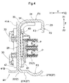
FIG. 4 is a cross-sectional view of a first traveling rail in a second embodiment. -
FIG. 5 is a cross-sectional view of a first traveling rail in another embodiment. -
FIG. 6 is a cross-sectional view of a first traveling rail in another embodiment. -
FIG. 7 is a cross-sectional view of a first traveling rail in another embodiment. -
FIG. 8 is a cross-sectional view of a first traveling rail in another embodiment. -
FIG. 9 is a cross-sectional view of a first traveling rail in another embodiment. - A traveling rail and an article transport facility according to one or more embodiments will now be described with reference to the drawings.
- The article transport facility shown in
FIG. 1 includesarticle transport vehicles 1 for transporting articles W, first traveling rails 2 (corresponding to a traveling rail) that each define a traveling path for thearticle transport vehicles 1,second traveling rails 3 that each define the traveling path for thearticle transport vehicles 1 and are spaced apart from thefirst traveling rails 2 in a second width direction Y2, wiring 44 continuous in a traveling path direction X in which the traveling path extends, andarticle storage shelves 4 for storing articles W. The direction orthogonal to the traveling path direction X as viewed in a vertical direction Z is a width direction Y. The width direction Y includes a first width direction Y1 and the second width direction Y2 that are opposite to each other. - A pair of
article storage shelves 4 are installed to face each other across the traveling path. Eacharticle storage shelve 4 in the pair includes multiplefront posts 6 that are erected adjacent to one another in the traveling path direction X, multiplerear posts 7 that are erected in the traveling path direction X at positions opposite to the traveling path in the width direction Y from thefront posts 6, andmultiple shelf boards 8 arranged in the vertical direction Z. - The
article storage shelves 4 support theshelf boards 8 arranged in the vertical direction Z with thefront posts 6 and therear posts 7. Thearticle storage shelves 4 receive articles W on theshelf boards 8. - The
article transport vehicles 1 are installed on therespective shelf boards 8 that are arranged in the vertical direction Z. - The article transport facility includes a
loading lifter 11 and anunloading lifter 12 that each can be raised and lowered in the vertical direction Z, andloading conveyors 13 and unloadingconveyors 14 installed on therespective shelf boards 8 that are arranged in the vertical direction Z. - In the article transport facility, an article W placed on the
loading lifter 11 is transported by theloading lifter 11 to one of theloading conveyors 13 that are located at different levels. The article W on oneloading conveyor 13 is then transported onto theshelf board 8 corresponding to theloading conveyor 13 by thearticle transport vehicle 1 corresponding to theloading conveyor 13 located at the corresponding level. In the article transport facility, each article W on theshelf board 8 is transported onto theunloading conveyor 14 located at the level corresponding to theshelf board 8 by thearticle transport vehicle 1 corresponding to theshelf board 8 located at the corresponding level. The article W supported on one of theunloading conveyors 14 at the different levels is unloaded out of the article transport facility as being moved with theunloading lifter 12. - Each
article transport vehicle 1 includes atraveling unit 16 that travels in the traveling path direction X and atransferer 17 for transferring an article W in the width direction Y Thetraveling unit 16 supports thetransferer 17. Thetransferer 17 includes a pair offork portions 21 that can be advanced and retracted in the width direction Y and can have a variable distance between them. As shown inFIGs. 2 and 3 , the travelingunit 16 includesmultiple wheels 18,multiple guide wheels 19, andcontact power receivers 20 that can come in contact with a power feeder 23 (described below) to receive power. Themultiple wheels 18 includewheels 18 to roll on the first travelingrail 2 andwheels 18 to roll on the second travelingrail 3. In the present embodiment, themultiple guide wheels 19 come in contact with and are guided by the first travelingrail 2. - The
power receivers 20 receive power, which is then fed to the travelingunit 16 and thetransferer 17 as driving power. The travelingunit 16 travels on the first travelingrail 2 and the second travelingrail 3 in the traveling path direction X while being guided by the first travelingrail 2 with some or all of thewheels 18 being driven and rotating. As thefork portions 21 are driven, thetransferer 17 transfers an article W between the travelingunit 16 and theshelf board 8, and between the travelingunit 16 and theloading conveyor 13 or the unloadingconveyor 14. - The
first traveling rails 2 will now be described. As shown inFIG. 2 , each first travelingrail 2 includes arail unit 22 extending in the traveling path direction X and thepower feeder 23 that feeds power to thepower receivers 20 in thearticle transport vehicle 1. In the present embodiment, each first travelingrail 2 is an edge of thecorresponding shelf board 8 in the second width direction Y2. For an article W to be transferred by thetransferer 17 between the travelingunit 16 and theshelf board 8, the article W moves in the width direction Y while sliding on a top surface of the first traveling rail 2 (a traveling surface F1 described later). - The
rail unit 22 includes a first upper plate segment 26 (corresponding to an upper plate segment), a first lower plate segment 27 (corresponding to a lower plate segment), and a first intermediate plate segment 28 (corresponding to an intermediate plate segment). In the present embodiment, therail unit 22 further includes a first flange 29 (corresponding to a flange). The firstupper plate segment 26 is a plate extending continuously in the traveling path direction X and extending in the width direction Y. The firstlower plate segment 27 is a plate extending continuously in the traveling path direction X and extending in the width direction Y The firstlower plate segment 27 is at a position in a downward direction Z2 from the firstupper plate segment 26. The firstintermediate plate segment 28 is a plate extending continuously in the traveling path direction X and extending in the vertical direction Z. The firstintermediate plate segment 28 joins an edge of the firstupper plate segment 26 in the first width direction Y1 and an edge of the firstlower plate segment 27 in the first width direction Y1. Thefirst flange 29 is a plate extending continuously in the traveling path direction X and extending in the vertical direction Z. Thefirst flange 29 extends, in the downward direction Z2, from an edge of the firstupper plate segment 26 in the second width direction Y2. In the present embodiment, therail unit 22 includes the firstupper plate segment 26, the firstlower plate segment 27, and the firstintermediate plate segment 28, thus being in an angled C shape as viewed in the traveling path direction X. - The
rail unit 22 is connected to the front posts 6. In the present embodiment, therail unit 22 is connected to at least a pair offront posts 6 that are adjacent to each other in the traveling path direction X. More specifically, therail unit 22 is connected to each of thesefront posts 6 adjacent in the traveling path direction X with afirst fastener 33 at the corresponding position. To connect therail unit 22 to eachfront post 6, thefirst fastener 33 is placed through thefront post 6 and the firstintermediate plate segment 28 and is screwed into afastening plate 34. Thefastening plate 34 includes a portion along the firstupper plate segment 26 and a portion along the firstintermediate plate segment 28, and has an overall L shape as viewed in the traveling path direction. Thefastening plate 34 is a plate with an internal thread and is located opposite to thefront posts 6 with the firstintermediate plate segment 28 between them. In the present embodiment, thefastening plate 34 is located in a space S defined by the firstupper plate segment 26, the firstintermediate plate segment 28, and the firstlower plate segment 27 in therail unit 22. - The
power feeder 23 is placed in the space S in therail unit 22. Thepower feeder 23 extends continuously in the traveling path direction X. In the present embodiment, thepower feeder 23 is supported on the firstintermediate plate segment 28. In more detail, thepower feeder 23 is connected to the firstintermediate plate segment 28, and is spaced apart from the firstlower plate segment 27 in an upward direction Z1 and is spaced apart from the firstupper plate segment 26 in the downward direction Z2. More specifically, thepower feeder 23 is connected to the firstintermediate plate segment 28 at a position in the downward direction Z2 from the midpoint on the firstintermediate plate segment 28 in the vertical direction Z. Thus, the distance between thepower feeder 23 and the firstupper plate segment 26 in the vertical direction Z is greater than the distance between thepower feeder 23 and the firstlower plate segment 27 in the vertical direction Z. - The first
upper plate segment 26 has the traveling surface F1 facing in the upward direction Z1. The traveling surface F1 allows thewheels 18 in thearticle transport vehicle 1 to roll. An arc-shaped first curved portion 30 (corresponding to a curved portion) as viewed in the traveling path direction X is at the joint between the firstupper plate segment 26 and the firstintermediate plate segment 28. Although the joint between the firstupper plate segment 26 and thefirst flange 29 and the joint between the firstlower plate segment 27 and the firstintermediate plate segment 28 are also arc-shaped as viewed in the traveling path direction, the firstcurved portion 30 is arc-shaped with a greater radius than those joints. - The
first flange 29 has first guide surfaces F2 (corresponding to guide surfaces) on which theguide wheels 19 in thearticle transport vehicle 1 rolls. In the present embodiment, the two surfaces of thefirst flange 29 facing in the first width direction Y1 and in the second width direction Y2 serve as the first guide surfaces F2. Thus, thefirst flange 29 has the first guide surface F2 facing in the first width direction Y1 in contact with theguide wheels 19 to restrict thearticle transport vehicle 1 from moving in the second width direction Y2, and has the other first guide surface F2 facing in the second width direction Y2 in contact with theguide wheels 19 to restrict thearticle transport vehicle 1 from moving in the first width direction Y1. This allows thearticle transport vehicle 1 to be guided in the traveling path direction X. - The first
lower plate segment 27 includes a first lowerflat portion 27A (corresponding to a lower flat portion) extending in the traveling path direction X and in the width direction Y, and afirst groove 27B (corresponding to a groove) protruding in the downward direction Z2 from the first lowerflat portion 27A and extending continuously in the traveling path direction X. In the present embodiment, thefirst groove 27B extends continuously in the second width direction Y2 from the first lowerflat portion 27A. In the illustrated example, an edge of thefirst groove 27B in the second width direction Y2 is an edge of the firstlower plate segment 27 in the second width direction Y2. - In more detail, the first lower
flat portion 27A extends continuously in the second width direction Y2 from the edge of the firstintermediate plate segment 28 in the downward direction Z2, and thefirst groove 27B extends continuously in the second width direction Y2 from the edge of the first lowerflat portion 27A. The edge of thefirst groove 27B is the edge of the firstlower plate segment 27 in the second width direction Y2. - In the present embodiment, the
first groove 27B fully overlaps the firstupper plate segment 26 as viewed in the vertical direction. More specifically, thefirst groove 27B has the edge in the second width direction Y2 at a position in the first width direction Y1 from the first guide surface F2 of thefirst flange 29 facing in the first width direction Y1. Also, thefirst groove 27B has an edge in the first width direction Y1 at a position in the second width direction Y2 from the edge of the flat portion of the firstupper plate segment 26 in the first width direction Y1. The flat portion of the firstupper plate segment 26 is a portion of the firstupper plate segment 26 excluding the arc-shaped firstcurved portion 30 joining the firstupper plate segment 26 and the firstintermediate plate segment 28. - The lowermost portion of a groove surface F3, which is the surface of the
first groove 27B facing in the upward direction Z1, is at a position in the second width direction Y2 from a contact position P of thepower feeder 23 with eachpower receiver 20. The contact position P is a position on thepower feeder 23 that can come in contact with eachpower receiver 20. In the present embodiment, the position of thefirst groove 27B is defined with reference to an innermost position in the first width direction Y1 within a range in which thepower feeder 23 can come in contact with eachpower receiver 20. In the present embodiment, the lowermost portion of the groove surface F3 is at a position in the second width direction Y2 from the edge of thepower feeder 23 in the second width direction Y2. In the illustrated example, further, thefirst groove 27B has the edge in the first width direction Y1 at a position in the first width direction Y1 from the edge of thepower feeder 23 in the second width direction Y2. This structure allows any friction dust produced at the contact position between thepower feeder 23 and thepower receivers 20 to be received on the groove surface F3. - The
first groove 27B partially overlaps thepower feeder 23 as viewed in the vertical direction in the present embodiment, and thepower feeder 23 is spaced apart from the firstlower plate segment 27 in the upward direction Z1. This structure allows any friction dust produced upon contact of thepower receivers 20 with thepower feeder 23 to accumulate also in a portion of thefirst groove 27B overlapping thepower feeder 23 as viewed in the vertical direction. - The cross section of the
first groove 27B orthogonal to the traveling path direction X may have an arc shape with a central angle of less than 180°. More specifically, the cross section of thefirst groove 27B may have an arc shape with a central angle less than 120°, or specifically an arc shape with a central angle less than 90°. In the present embodiment, the cross section of thefirst groove 27B has an arc shape with a central angle of 75 to 85°. In the illustrated example, thefirst groove 27B has the edge in the first width direction Y1 and the edge in the second width direction Y2 that are at the same height, and has the lowermost position of the groove surface F3 at the middle of thefirst groove 27B in the width direction Y - As shown in
FIG. 3 , each second travelingrail 3 includes arail unit 22 extending in the traveling path direction X, but includes nopower feeder 23, unlike each first travelingrail 2. - Each second traveling
rail 3 includes arail unit 22 including a secondupper plate segment 36, a secondlower plate segment 37, and a secondintermediate plate segment 38. In the present embodiment, therail unit 22 in the second travelingrail 3 further includes asecond flange 39. The secondupper plate segment 36 is a plate extending continuously in the traveling path direction X and extending in the width direction Y The secondlower plate segment 37 is a plate extending continuously in the traveling path direction X and extending in the width direction Y The secondlower plate segment 37 is at a position in the downward direction Z2 from the secondupper plate segment 36. The secondintermediate plate segment 38 is a plate extending continuously in the traveling path direction X and extending in the vertical direction Z. The secondintermediate plate segment 38 joins an edge of the secondupper plate segment 36 in the second width direction Y2 and an edge of the secondlower plate segment 37 in the second width direction Y2. Thesecond flange 39 is a plate extending continuously in the traveling path direction X and extending in the vertical direction Z. Thesecond flange 39 extends, in the downward direction Z2, from an edge of the secondupper plate segment 36 in the first width direction Y1. - The second
upper plate segment 36 has a second traveling surface F4 facing in the upward direction Z1. The second traveling surface F4 allows thewheels 18 in thearticle transport vehicle 1 to roll. An arc-shaped secondcurved portion 40 as viewed in the traveling path direction X is at the joint between the secondupper plate segment 36 and the secondintermediate plate segment 38, similarly to the joint between the firstupper plate segment 26 and the firstintermediate plate segment 28. Further, the secondlower plate segment 37 includes a second lowerflat portion 37A extending in the traveling path direction X and in the width direction Y, and asecond groove 37B protruding in the downward direction Z2 from the second lowerflat portion 37A and extending continuously in the traveling path direction X. The surface of thesecond groove 37B facing in the upward direction Z1 is a second groove surface F5. In the present embodiment, thewiring 44 is installed to extend continuously in the traveling path direction X in the article transport facility. Thesecond groove 37B on the second travelingrail 3 may be used as a groove to receive thewiring 44. In other words, thewiring 44 is located in thesecond groove 37B. More specifically, thewiring 44 is in contact with the second groove surface F5 of thesecond groove 37B. - In this manner, the
rail unit 22 in the second travelingrail 3 includes the secondupper plate segment 36, the secondlower plate segment 37, the secondintermediate plate segment 38, and thesecond flange 39. The secondlower plate segment 37 includes the second lowerflat portion 37A and thesecond groove 37B. Therail unit 22 in the second travelingrail 3 is thus symmetric to therail unit 22 in the first travelingrail 2 in the width direction Y. For example, therail unit 22 for the first travelingrail 2 may thus be used for the second travelingrail 3 by turning therail unit 22 by 180° about an axis extending in the vertical direction Z. In the present embodiment, therail unit 22 for the second travelingrail 3 does not have a hole or any other structure to fasten thepower feeder 23, and thus thepower feeder 23 cannot be fixed to therail unit 22. Thus, therail unit 22 in the first travelingrail 2 and therail unit 22 in the second travelingrail 3 do not have the same shape, although therail unit 22 in the second travelingrail 3 is formed using the same member as therail unit 22 in the first travelingrail 2. - A traveling rail and an article transport facility according to a second embodiment will now be described with reference to
FIG. 4 . Arail unit 22 in the present embodiment will be described, focusing on its differences from the corresponding component in the first embodiment described above. The components that will not be described herein are the same as described in the first embodiment above. - In the present embodiment, the
power feeder 23 is connected to the firstintermediate plate segment 28 and is at the midpoint on the firstintermediate plate segment 28 in the vertical direction Z. Thus, the distance between thepower feeder 23 and the firstupper plate segment 26 in the vertical direction Z and the distance between thepower feeder 23 and the firstlower plate segment 27 in the vertical direction Z are substantially the same. - In the present embodiment, the
first groove 27B overlaps both the firstupper plate segment 26 and thefirst flange 29 as viewed in the vertical direction. More specifically, thefirst groove 27B has the edge in the second width direction Y2 at a position in the second width direction Y2 from the first guide surface F2 of thefirst flange 29 facing in the first width direction Y1. In the illustrated example, thefirst groove 27B has the edge in the second width direction Y2 at a position in the first width direction Y1 from the first guide surface F2 of thefirst flange 29 facing in the second width direction Y2. In other words, thefirst groove 27B has the edge in the second width direction Y2 within the range in the width direction Y overlapping thefirst flange 29 as viewed in the vertical direction. Also, thefirst groove 27B has the edge in the first width direction Y1 at a position in the second width direction Y2 from the edge of the flat portion of the firstupper plate segment 26 in the first width direction Y1. - In the present embodiment as well, the lowermost portion of the groove surface F3, which is the surface of the
first groove 27B facing in the upward direction Z1, is at a position in the second width direction Y2 from the contact position P of thepower feeder 23 with eachpower receiver 20. In the present embodiment, the lowermost portion of the groove surface F3 is at a position in the first width direction Y1 from the edge of thepower feeder 23 in the second width direction Y2. In contrast, thefirst groove 27B has the edge in the second width direction Y2 at a position in the second width direction Y2 from the edge of thepower feeder 23 in the second width direction Y2. - In the present embodiment, the first
intermediate plate segment 28 is fixed to areinforcement 41 reinforcing therail unit 22, and has the surface in the first width direction Y1 being in contact with thereinforcement 41. Thereinforcement 41 includes aplaner portion 41A and aprojection 41B. Theplaner portion 41A is a plate extending continuously in the traveling path direction X and extending in the vertical direction Z. Theprojection 41B extends continuously in the traveling path direction X and protrudes, in the first width direction Y1, from the edge of theplaner portion 41A in the downward direction Z2. With the surface of the firstintermediate plate segment 28 in the first width direction Y1 in contact with the surface of theplaner portion 41A of thereinforcement 41 in the second width direction Y2, asecond fastener 43 is placed through the firstintermediate plate segment 28 and theplaner portion 41A and is screwed into ascrew plate 42. The firstintermediate plate segment 28 is thus fixed to thereinforcement 41. Thescrew plate 42 is a plate with an internal thread. Thescrew plate 42 is located opposite to the firstintermediate plate segment 28 with thereinforcement 41 between them. In the present embodiment, thereinforcement 41 is located without overlapping anyfront posts 6 in the traveling path direction X. - A traveling rail and an article transport facility according to other embodiments will now be described.
- (1) In the first and second embodiments described above, the second traveling
rail 3 includes the secondupper plate segment 36, the secondlower plate segment 37, and the secondintermediate plate segment 38, and the secondlower plate segment 37 includes the second lowerflat portion 37A and thesecond groove 37B. However, the embodiments are not limited to these structures. The shape of the second travelingrail 3 may be modified as appropriate. For example, the secondlower plate segment 37 may not include one or both of the second lowerflat portion 37A and thesecond groove 37B. - (2) In the first and second embodiments described above, the first lower
flat portion 27A is located adjacent to thefirst groove 27B in the first width direction Y1 alone. However, the embodiments are not limited to this structure. For example, as shown inFIG. 5 , first lowerflat portions 27A may be at positions in the first width direction Y1 and in the second width direction Y2 from thefirst groove 27B. In some embodiments, a first lowerflat portion 27A may be located adjacent to thefirst groove 27B in the second width direction Y2 alone. In other words, thefirst groove 27B may have the edge in the second width direction Y2 that is not the edge of the firstlower plate segment 27 in the second width direction Y2. - (3) In the first and second embodiments described above, the lowermost portion of the groove surface F3 of the
first groove 27B is at a position in the second width direction Y2 from the contact position P of thepower feeder 23 with eachpower receiver 20. However, the embodiments are not limited to this structure. The lowermost portion of the groove surface F3 may be at the same position as the contact position P of thepower feeder 23 with eachpower receiver 20 or may be at a position in the first width direction Y1 from the contact position P. - (4) In the first and second embodiments described above, the
power feeder 23 is spaced apart from the firstlower plate segment 27 in the upward direction Z1 and is spaced apart from the firstupper plate segment 26 in the downward direction Z2. However, the embodiments are not limited to this structure. For example, thepower feeder 23 may be in contact with the firstlower plate segment 27 or in contact with the firstupper plate segment 26. - (5) In the first and second embodiments described above, the
power feeder 23 is supported on the firstintermediate plate segment 28. However, the embodiments are not limited to this structure. For example, thepower feeder 23 may be supported on the firstupper plate segment 26 or on the firstlower plate segment 27. - (6) In the first and second embodiments described above, the
first groove 27B fully overlaps the firstupper plate segment 26 as viewed in the vertical direction. However, the embodiments are not limited to this structure. As viewed in the vertical direction, for example, thefirst groove 27B may partly extend beyond the firstupper plate segment 26 in the second width direction Y2. - (7) In the first and second embodiments described above, the cross section of the
first groove 27B orthogonal to the traveling path direction X (hereafter, simply the cross section of thefirst groove 27B) is arc-shaped. However, the embodiments are not limited to this structure. The cross section of thefirst groove 27B may be in any other shape. As shown inFIG. 6 , for example, the cross section of thefirst groove 27B may be V-shaped. As shown inFIG. 7 , the cross section of thefirst groove 27B may be trapezoidal. As shown inFIG. 8 , the cross section of thefirst groove 27B may be U-shaped. - (8) In the second embodiment described above, the
reinforcement 41 is fixed to the surface of the firstintermediate plate segment 28 in the first width direction Y1. However, the embodiment is not limited to this structure. In the second embodiment, for example, thereinforcement 41 may not be fixed to the surface of the firstintermediate plate segment 28 in the first width direction Y1. In the first embodiment, thereinforcement 41 is not fixed to the surface of the firstintermediate plate segment 28 in the first width direction Y1. In the first embodiment, thereinforcement 41 may be fixed to the surface of the firstintermediate plate segment 28 in the first width direction Y1. - (9) In the first and second embodiments described above, the
rail unit 22 in the first travelingrail 2 includes thefirst flange 29 having the first guide surfaces F2. However, the embodiments are not limited to this structure. For example, the first guide surfaces F2 may be included in a member other than therail unit 22 in the first travelingrail 2, and therail unit 22 in the first travelingrail 2 may not include thefirst flange 29. The same applies to the second travelingrail 3. - (10) In the first and second embodiments described above, the first
curved portion 30 that is arc-shaped is at the joint between the firstupper plate segment 26 and the firstintermediate plate segment 28 as viewed in the traveling path direction. However, the embodiments are not limited to this structure. The shape of the joint between the firstupper plate segment 26 and the firstintermediate plate segment 28 may be modified as appropriate. As shown inFIG. 9 , for example, the joint between the firstupper plate segment 26 and the firstintermediate plate segment 28 may include aslope 31 that slopes in the downward direction Z2 as theslope 31 extends in the first width direction Y1 as viewed in the traveling path direction. In some embodiments, the firstupper plate segment 26 and the firstintermediate plate segment 28 may be orthogonal to each other as viewed in the traveling path direction. - (11) In the first and second embodiments described above, the traveling
unit 16 travels in the traveling path direction X as being guided by the first travelingrail 2 alone, among the first travelingrail 2 and the second travelingrail 3. However, the embodiments are not limited to this structure. For example, the travelingunit 16 may travel in the traveling path direction X as being guided by the second travelingrail 3 alone, among the first travelingrail 2 and the second travelingrail 3. The travelingunit 16 may travel in the traveling path direction X as being guided by both the first travelingrail 2 and the second travelingrail 3. For the travelingunit 16 traveling in the traveling path direction X as being guided by both the first travelingrail 2 and the second travelingrail 3, thefirst flange 29 may receive theguide wheels 19 on its two surfaces in the width direction Y, and thesecond flange 39 may receive theguide wheels 19 on its two surfaces in the width direction Y. Thefirst flange 29 may receive theguide wheels 19 in the first width direction Y1 alone, and thesecond flange 39 may receive theguide wheels 19 in the second width direction Y2 alone. Thefirst flange 29 may receive theguide wheels 19 in the second width direction Y2 alone, and thesecond flange 39 may receive theguide wheels 19 in the first width direction Y1 alone. - (12) The structure described in each of the above embodiments may be combined with any other structures described in the other embodiments unless any contradiction arises. The embodiments described herein are merely illustrative in all respects and may be modified variously as appropriate without departing from the spirit and scope of the present disclosure.
- The overview of the traveling rail and the article transport facility described above will be provided.
- A traveling rail defines a traveling path for an article transport vehicle for transporting an article. The traveling rail includes a rail unit extending in a traveling path direction in which the traveling path extends, and a power feeder that feeds power to a power receiver in the article transport vehicle through contact with the power receiver. The rail unit includes an upper plate segment being a plate extending continuously in the traveling path direction and extending in a width direction, a lower plate segment being a plate extending continuously in the traveling path direction and extending in the width direction, and being at a position in a downward direction from the upper plate segment, and an intermediate plate segment being a plate extending continuously in the traveling path direction and extending in a vertical direction, and joining an edge of the upper plate segment in a first width direction and an edge of the lower plate segment in the first width direction. The width direction is a direction orthogonal to the traveling path direction as viewed in the vertical direction. The width direction includes the first width direction and a second width direction opposite to each other. The power feeder is located in a space defined by the upper plate segment, the intermediate plate segment, and the lower plate segment in the rail unit and extends continuously in the traveling path direction. The upper plate segment includes a traveling surface facing in an upward direction to allow a wheel in the article transport vehicle to roll on the traveling surface. The lower plate segment includes a lower flat portion being a flat plate extending in the traveling path direction and the width direction, and a groove protruding in the downward direction from the lower flat portion and extending continuously in the traveling path direction.
- The structure including the power feeder located in the space defined by the upper plate segment, the intermediate plate segment, and the lower plate segment in the rail unit allows friction dust produced upon contact of the power receiver with the power feeder to be received on the lower plate segment in the rail unit. This structure reduces scattering of friction dust around. The lower plate segment includes the lower flat portion and the groove to facilitate friction dust received on the lower plate segment to accumulate in the groove. This structure thus reduces scattering of friction dust from the traveling rail and allows easy removal of friction dust accumulating on the lower plate segment.
- The groove may have a groove surface facing in the upward direction, and the groove surface may include a lowermost portion at a position in the second width direction from a contact position of the power feeder with the power receiver.
- This structure allows any friction dust produced at the contact position between the power feeder and the power receiver to be received in the groove. This thus facilitates friction dust received on the lower plate segment to accumulate in the groove.
- The groove may extend continuously in the second width direction from the lower flat portion, and an edge of the groove in the second width direction may be an edge of the lower plate segment in the second width direction.
- The structure allows any friction dust moving in the second width direction after being received on the lower flat portion to accumulate in the groove, and thus effectively reduces scattering of friction dust out of the traveling rail.
- The power feeder may be spaced apart from the lower plate segment in the upward direction.
- This structure allows any friction dust produced at the contact position between the power feeder and the power receiver to accumulate in the groove. This structure also allows passage of air between the power feeder and the lower plate segment, thus facilitating heat dissipation from the power feeder.
- The power feeder may be supported on the intermediate plate segment.
- In this structure, the power feeder may be spaced apart from the lower plate segment in the upward direction.
- The groove may fully overlap the upper plate segment as viewed in the vertical direction.
- This structure reduces the likelihood of dust produced above the upper plate segment entering the space defined by the upper plate segment, the intermediate plate segment, and the lower plate segment, and thus reduces accumulation of dust in the groove after being produced outside the space.
- A cross section of the groove orthogonal to the traveling path direction may have an arc shape with a central angle of less than 180°.
- In this structure, the cross section of the groove has an arc shape with a central angle of less than 180°, thus allowing the groove to be relatively shallow. This shape allows easy removal of friction dust accumulating in the groove.
- The intermediate plate segment may be fixed to a reinforcement reinforcing the rail unit, and may have a surface in the first width direction being in contact with the reinforcement.
- In this structure, the intermediate plate segment that is a plate extending in the vertical direction is fixed to the reinforcement and has its surface in the first width direction being in contact with the reinforcement, thus allowing the reinforcement to properly reinforce the rail unit.
- The rail unit may further include a flange. The flange may be a plate extending continuously in the traveling path direction and extending in the vertical direction. The flange may extend in the downward direction from an edge of the upper plate segment in the second width direction. The flange may include a guide surface to allow a guide wheel in the article transport vehicle to roll on the guide surface.
- In this structure, the flange in the rail unit has the guide surface. The rail unit can guide the guide wheel in the article transport vehicle in the traveling path direction. Further, the flange extends in the downward direction from the edge of the upper plate segment in the second width direction. The upper plate segment with the traveling surface can easily be highly durable.
- An arc-shaped curved portion as viewed in the traveling path direction may be at a joint between the upper plate segment and the intermediate plate segment.
- This structure includes the curved portion at the joint. The upper plate segment with the traveling surface can thus easily be highly durable. For an article to slide on the upper surface of the upper plate segment from a position in the first width direction toward a position in the second width direction, the article is less likely to be stuck on the surface.
- An article transport facility includes a first traveling rail being the traveling rail, a second traveling rail spaced apart from the first traveling rail in the second width direction, and wiring extending continuously in the traveling path direction. The second traveling rail includes a rail unit. The rail unit includes a second upper plate segment being a plate extending continuously in the traveling path direction and extending in a width direction, a second lower plate segment being a plate extending continuously in the traveling path direction and extending in the width direction, and being at a position in the downward direction from the second upper plate segment, and a second intermediate plate segment being a plate extending continuously in the traveling path direction and extending in the vertical direction, and joining an edge of the second upper plate segment in the second width direction and an edge of the second lower plate segment in the second width direction. The second upper plate segment includes a second traveling surface facing in the upward direction to allow a wheel in the article transport vehicle to roll on the second traveling surface. The second lower plate segment includes a second lower flat portion being a flat plate extending in the traveling path direction and the width direction, and a second groove protruding in the downward direction from the second lower flat portion and extending continuously in the traveling path direction. The wiring is located in the second groove.
- This structure allows the article transport vehicle to travel along the first traveling rail and the second traveling rail to transport an article. The wiring located in the second groove on the second traveling rail is less likely to move in the width direction. The second traveling rail has the same structure as the first traveling rail and includes the second upper plate segment, the second lower plate segment, and the second intermediate plate segment. The first traveling rail and the second traveling rail can thus be formed from members with the same cross section.
- The technique according to one or more embodiments of the present disclosure can be used for a traveling rail including a rail unit and a power feeder, and for an article transport facility including the traveling rail.
-
- 1
- article transport vehicle
- 2
- first traveling rail (traveling rail)
- 3
- second traveling rail
- 18
- wheel
- 20
- power receiver
- 23
- power feeder
- 26
- first upper plate segment (upper plate segment)
- 27
- first lower plate segment (lower plate segment)
- 27A
- first lower flat portion (lower flat portion)
- 27B
- first groove (groove)
- 28
- first intermediate plate segment (intermediate plate segment)
- 29
- first flange (flange)
- 30
- curved portion
- 36
- second upper plate segment
- 37
- second lower plate segment
- 37A
- second lower flat portion
- 37B
- second groove
- 38
- second intermediate plate segment
- 41
- reinforcement
- 44
- wiring
- F1
- first traveling surface (traveling surface)
- F2
- first guide surface (guide surface)
- F3
- first groove surface (groove surface)
- F4
- second traveling surface
- S
- space
- W
- article
- X
- traveling path direction
- Y
- width direction
- Y1
- first width direction
- Y2
- second width direction
- Z
- vertical direction
- Z1
- upward direction
- Z2
- downward direction
Claims (11)
- A traveling rail defining a traveling path for an article transport vehicle for transporting an article, the traveling rail comprising:a rail unit extending in a traveling path direction in which the traveling path extends; anda power feeder configured to feed power to a power receiver in the article transport vehicle through contact with the power receiver;wherein the rail unit includes an upper plate segment being a plate extending continuously in the traveling path direction and extending in a width direction, a lower plate segment being a plate extending continuously in the traveling path direction and extending in the width direction, and being at a position in a downward direction from the upper plate segment, and an intermediate plate segment being a plate extending continuously in the traveling path direction and extending in a vertical direction, and joining an edge of the upper plate segment in a first width direction and an edge of the lower plate segment in the first width direction, where the width direction is a direction orthogonal to the traveling path direction as viewed in the vertical direction, and the width direction includes the first width direction and a second width direction opposite to each other,the power feeder is located in a space defined by the upper plate segment, the intermediate plate segment, and the lower plate segment in the rail unit and extends continuously in the traveling path direction,the upper plate segment includes a traveling surface facing in an upward direction to allow a wheel in the article transport vehicle to roll on the traveling surface, andthe lower plate segment includes a lower flat portion being a flat plate extending in the traveling path direction and the width direction, and a groove protruding in the downward direction from the lower flat portion and extending continuously in the traveling path direction.
- The traveling rail according to claim 1, wherein
the groove has a groove surface facing in the upward direction, and the groove surface includes a lowermost portion at a position in the second width direction from a contact position of the power feeder with the power receiver. - The traveling rail according to claim 1 or claim 2, whereinthe groove extends continuously in the second width direction from the lower flat portion, andan edge of the groove in the second width direction is an edge of the lower plate segment in the second width direction.
- The traveling rail according to any one of claims 1 to 3, wherein
the power feeder is spaced apart from the lower plate segment in the upward direction. - The traveling rail according to any one of claims 1 to 4, wherein
the power feeder is supported on the intermediate plate segment. - The traveling rail according to any one of claims 1 to 5, wherein
the groove fully overlaps the upper plate segment as viewed in the vertical direction. - The traveling rail according to any one of claims 1 to 6, wherein
a cross section of the groove orthogonal to the traveling path direction has an arc shape with a central angle of less than 180°. - The traveling rail according to any one of claims 1 to 7, wherein
the intermediate plate segment is fixed to a reinforcement reinforcing the rail unit and has a surface in the first width direction being in contact with the reinforcement. - The traveling rail according to any one of claims 1 to 8, whereinthe rail unit further includes a flange,the flange is a plate extending continuously in the traveling path direction and extending in the vertical direction, and the flange extends in the downward direction from an edge of the upper plate segment in the second width direction, andthe flange includes a guide surface to allow a guide wheel in the article transport vehicle to roll on the guide surface.
- The traveling rail according to any one of claims 1 to 9, wherein
an arc-shaped curved portion as viewed in the traveling path direction is at a joint between the upper plate segment and the intermediate plate segment. - An article transport facility, comprising:a first traveling rail being the traveling rail according to any one of claims 1 to 10;a second traveling rail spaced apart from the first traveling rail in the second width direction; andwiring extending continuously in the traveling path direction,wherein the second traveling rail includes a rail unit, and the rail unit includes a second upper plate segment being a plate extending continuously in the traveling path direction and extending in a width direction, a second lower plate segment being a plate extending continuously in the traveling path direction and extending in the width direction, and being at a position in the downward direction from the second upper plate segment, and a second intermediate plate segment being a plate extending continuously in the traveling path direction and extending in the vertical direction, and joining an edge of the second upper plate segment in the second width direction and an edge of the second lower plate segment in the second width direction,the second upper plate segment includes a second traveling surface facing in the upward direction to allow a wheel in the article transport vehicle to roll on the second traveling surface,the second lower plate segment includes a second lower flat portion being a flat plate extending in the traveling path direction and the width direction, and a second groove protruding in the downward direction from the second lower flat portion and extending continuously in the traveling path direction, andthe wiring is located in the second groove.
Applications Claiming Priority (2)
| Application Number | Priority Date | Filing Date | Title |
|---|---|---|---|
| JP2019217857A JP7147735B2 (en) | 2019-12-02 | 2019-12-02 | Running rails and goods transport equipment |
| PCT/JP2020/029311 WO2021111674A1 (en) | 2019-12-02 | 2020-07-30 | Traveling rail and article transport facility |
Publications (2)
| Publication Number | Publication Date |
|---|---|
| EP4067262A1 true EP4067262A1 (en) | 2022-10-05 |
| EP4067262A4 EP4067262A4 (en) | 2024-02-28 |
Family
ID=76219349
Family Applications (1)
| Application Number | Title | Priority Date | Filing Date |
|---|---|---|---|
| EP20897241.4A Pending EP4067262A4 (en) | 2019-12-02 | 2020-07-30 | TRACK RAIL AND GOODS TRANSPORT SYSTEM |
Country Status (5)
| Country | Link |
|---|---|
| US (1) | US12485932B2 (en) |
| EP (1) | EP4067262A4 (en) |
| JP (1) | JP7147735B2 (en) |
| TW (1) | TWI850436B (en) |
| WO (1) | WO2021111674A1 (en) |
Families Citing this family (4)
| Publication number | Priority date | Publication date | Assignee | Title |
|---|---|---|---|---|
| WO2021220686A1 (en) * | 2020-04-30 | 2021-11-04 | 村田機械株式会社 | Traveling platform, and automatic storehouse |
| IT202000009502A1 (en) * | 2020-04-30 | 2021-10-30 | System Logistics S P A | ELEVATOR FOR AUTOMATIC STORAGE SYSTEMS |
| CN113666041B (en) * | 2021-08-12 | 2022-12-06 | 江阴名鸿车顶系统有限公司 | Shuttle goods shelf matched with shuttle car |
| CN119370506B (en) * | 2024-12-31 | 2025-04-11 | 山东轻工职业学院 | A logistics cargo transfer conveying device |
Family Cites Families (11)
| Publication number | Priority date | Publication date | Assignee | Title |
|---|---|---|---|---|
| GB2175555B (en) * | 1985-04-17 | 1989-02-01 | Daifuku Kk | Cart type conveying apparatus |
| KR970010584B1 (en) * | 1993-10-07 | 1997-06-28 | 가부시끼가이샤 다이후꾸 | Transporting system driven by linear motor having inductive power supply |
| JP3654417B2 (en) | 1999-02-10 | 2005-06-02 | 株式会社ダイフク | Goods storage facility |
| JP5842721B2 (en) | 2012-04-19 | 2016-01-13 | 株式会社ダイフク | Goods storage shelf |
| JP6350166B2 (en) * | 2014-09-19 | 2018-07-04 | 株式会社ダイフク | Goods transport cart |
| CN105584766B (en) | 2014-10-24 | 2018-06-22 | 国网甘肃省电力公司电力科学研究院 | Shuttle logistics system and its method of supplying power to |
| CN205221714U (en) | 2015-12-12 | 2016-05-11 | 山东恩堡工业自动化设备有限公司 | Multilayer shuttle |
| DE102016106725A1 (en) | 2016-04-12 | 2017-10-12 | Dematic Systems Gmbh | Rail-guided vehicle for loading and unloading goods in or out of a storage rack with damped guide rollers |
| CN206735132U (en) * | 2017-03-08 | 2017-12-12 | 江苏华章物流科技股份有限公司 | A kind of shuttle vehicle track |
| CN109748022B (en) | 2017-11-03 | 2020-09-01 | 北京京东乾石科技有限公司 | Shuttle car racking system and its control method |
| CN209051972U (en) * | 2018-09-10 | 2019-07-02 | 上海欧力德物流科技有限公司 | A kind of S-shaped track of the pallet fork formula four-way shuttle of low energy consumption |
-
2019
- 2019-12-02 JP JP2019217857A patent/JP7147735B2/en active Active
-
2020
- 2020-07-30 WO PCT/JP2020/029311 patent/WO2021111674A1/en not_active Ceased
- 2020-07-30 US US17/781,607 patent/US12485932B2/en active Active
- 2020-07-30 EP EP20897241.4A patent/EP4067262A4/en active Pending
- 2020-08-07 TW TW109126938A patent/TWI850436B/en active
Also Published As
| Publication number | Publication date |
|---|---|
| TW202134146A (en) | 2021-09-16 |
| TWI850436B (en) | 2024-08-01 |
| JP2021088418A (en) | 2021-06-10 |
| JP7147735B2 (en) | 2022-10-05 |
| US12485932B2 (en) | 2025-12-02 |
| US20230001959A1 (en) | 2023-01-05 |
| EP4067262A4 (en) | 2024-02-28 |
| WO2021111674A1 (en) | 2021-06-10 |
Similar Documents
| Publication | Publication Date | Title |
|---|---|---|
| EP4067262A1 (en) | Traveling rail and article transport facility | |
| EP3003928B1 (en) | Conveyor merge assembly | |
| US8978562B2 (en) | Rail guided vehicle system | |
| DE102008020052B4 (en) | Workpiece carrier device and conveyor system | |
| US8813943B2 (en) | Positive displacement sorter | |
| US3550535A (en) | Transportation system | |
| KR101407418B1 (en) | Overhead hoist transport | |
| US6675953B2 (en) | Conveyor system accessories | |
| US20110005902A1 (en) | Roller conveyor and a roller path system therefor | |
| US20070267271A1 (en) | Conveyor Roller Assembly | |
| CN110636980A (en) | Slat conveyors and transport accessories for such slat conveyors | |
| US20090026046A1 (en) | Conveying Installation for the Transport of Goods | |
| US20020166750A1 (en) | Vertical conveyor assembly with accumulating pallets | |
| US6997303B2 (en) | Carrier conveyor system | |
| KR101666800B1 (en) | Carriage system for loading object using carriage | |
| CN110770148B (en) | Conveying device with two conveying carts and covering means for covering the gap between the two conveying carts | |
| JP5842721B2 (en) | Goods storage shelf | |
| WO2024166449A1 (en) | Rack of automated warehouse | |
| CN109969537A (en) | A kind of horizontal tray | |
| KR102056222B1 (en) | Pipe-type conveyor belt apparatus having different friction portions | |
| KR101586695B1 (en) | Carriage | |
| CN219116318U (en) | RGV dolly and three-dimensional warehouse system | |
| JP2016124675A (en) | Sorting system, sorting method and guide unit | |
| KR20150072840A (en) | Carriage system and method for loading and unloading object using carriage | |
| KR20240082106A (en) | Shuttle running rail |
Legal Events
| Date | Code | Title | Description |
|---|---|---|---|
| STAA | Information on the status of an ep patent application or granted ep patent |
Free format text: STATUS: THE INTERNATIONAL PUBLICATION HAS BEEN MADE |
|
| PUAI | Public reference made under article 153(3) epc to a published international application that has entered the european phase |
Free format text: ORIGINAL CODE: 0009012 |
|
| STAA | Information on the status of an ep patent application or granted ep patent |
Free format text: STATUS: REQUEST FOR EXAMINATION WAS MADE |
|
| 17P | Request for examination filed |
Effective date: 20220630 |
|
| AK | Designated contracting states |
Kind code of ref document: A1 Designated state(s): AL AT BE BG CH CY CZ DE DK EE ES FI FR GB GR HR HU IE IS IT LI LT LU LV MC MK MT NL NO PL PT RO RS SE SI SK SM TR |
|
| DAV | Request for validation of the european patent (deleted) | ||
| DAX | Request for extension of the european patent (deleted) | ||
| REG | Reference to a national code |
Ref country code: DE Ref legal event code: R079 Free format text: PREVIOUS MAIN CLASS: B65G0001000000 Ipc: B65G0001040000 |
|
| A4 | Supplementary search report drawn up and despatched |
Effective date: 20240129 |
|
| RIC1 | Information provided on ipc code assigned before grant |
Ipc: B60M 1/30 20060101ALI20240123BHEP Ipc: B65G 1/06 20060101ALI20240123BHEP Ipc: B65G 1/04 20060101AFI20240123BHEP |