EP4065843B1 - Bistabiler trägheitsaktuator aus formgedächtnislegierung - Google Patents
Bistabiler trägheitsaktuator aus formgedächtnislegierung Download PDFInfo
- Publication number
- EP4065843B1 EP4065843B1 EP21714154.8A EP21714154A EP4065843B1 EP 4065843 B1 EP4065843 B1 EP 4065843B1 EP 21714154 A EP21714154 A EP 21714154A EP 4065843 B1 EP4065843 B1 EP 4065843B1
- Authority
- EP
- European Patent Office
- Prior art keywords
- shape memory
- memory alloy
- actuator
- inertial
- bistable
- Prior art date
- Legal status (The legal status is an assumption and is not a legal conclusion. Google has not performed a legal analysis and makes no representation as to the accuracy of the status listed.)
- Active
Links
Images




Classifications
-
- F—MECHANICAL ENGINEERING; LIGHTING; HEATING; WEAPONS; BLASTING
- F03—MACHINES OR ENGINES FOR LIQUIDS; WIND, SPRING, OR WEIGHT MOTORS; PRODUCING MECHANICAL POWER OR A REACTIVE PROPULSIVE THRUST, NOT OTHERWISE PROVIDED FOR
- F03G—SPRING, WEIGHT, INERTIA OR LIKE MOTORS; MECHANICAL-POWER PRODUCING DEVICES OR MECHANISMS, NOT OTHERWISE PROVIDED FOR OR USING ENERGY SOURCES NOT OTHERWISE PROVIDED FOR
- F03G7/00—Mechanical-power-producing mechanisms, not otherwise provided for or using energy sources not otherwise provided for
- F03G7/06—Mechanical-power-producing mechanisms, not otherwise provided for or using energy sources not otherwise provided for using expansion or contraction of bodies due to heating, cooling, moistening, drying or the like
- F03G7/061—Mechanical-power-producing mechanisms, not otherwise provided for or using energy sources not otherwise provided for using expansion or contraction of bodies due to heating, cooling, moistening, drying or the like characterised by the actuating element
- F03G7/0614—Mechanical-power-producing mechanisms, not otherwise provided for or using energy sources not otherwise provided for using expansion or contraction of bodies due to heating, cooling, moistening, drying or the like characterised by the actuating element using shape memory elements
- F03G7/06143—Wires
-
- F—MECHANICAL ENGINEERING; LIGHTING; HEATING; WEAPONS; BLASTING
- F03—MACHINES OR ENGINES FOR LIQUIDS; WIND, SPRING, OR WEIGHT MOTORS; PRODUCING MECHANICAL POWER OR A REACTIVE PROPULSIVE THRUST, NOT OTHERWISE PROVIDED FOR
- F03G—SPRING, WEIGHT, INERTIA OR LIKE MOTORS; MECHANICAL-POWER PRODUCING DEVICES OR MECHANISMS, NOT OTHERWISE PROVIDED FOR OR USING ENERGY SOURCES NOT OTHERWISE PROVIDED FOR
- F03G7/00—Mechanical-power-producing mechanisms, not otherwise provided for or using energy sources not otherwise provided for
- F03G7/06—Mechanical-power-producing mechanisms, not otherwise provided for or using energy sources not otherwise provided for using expansion or contraction of bodies due to heating, cooling, moistening, drying or the like
- F03G7/061—Mechanical-power-producing mechanisms, not otherwise provided for or using energy sources not otherwise provided for using expansion or contraction of bodies due to heating, cooling, moistening, drying or the like characterised by the actuating element
- F03G7/0616—Mechanical-power-producing mechanisms, not otherwise provided for or using energy sources not otherwise provided for using expansion or contraction of bodies due to heating, cooling, moistening, drying or the like characterised by the actuating element characterised by the material or the manufacturing process, e.g. the assembly
-
- F—MECHANICAL ENGINEERING; LIGHTING; HEATING; WEAPONS; BLASTING
- F03—MACHINES OR ENGINES FOR LIQUIDS; WIND, SPRING, OR WEIGHT MOTORS; PRODUCING MECHANICAL POWER OR A REACTIVE PROPULSIVE THRUST, NOT OTHERWISE PROVIDED FOR
- F03G—SPRING, WEIGHT, INERTIA OR LIKE MOTORS; MECHANICAL-POWER PRODUCING DEVICES OR MECHANISMS, NOT OTHERWISE PROVIDED FOR OR USING ENERGY SOURCES NOT OTHERWISE PROVIDED FOR
- F03G7/00—Mechanical-power-producing mechanisms, not otherwise provided for or using energy sources not otherwise provided for
- F03G7/06—Mechanical-power-producing mechanisms, not otherwise provided for or using energy sources not otherwise provided for using expansion or contraction of bodies due to heating, cooling, moistening, drying or the like
- F03G7/063—Mechanical-power-producing mechanisms, not otherwise provided for or using energy sources not otherwise provided for using expansion or contraction of bodies due to heating, cooling, moistening, drying or the like characterised by the mechanic interaction
- F03G7/0635—Mechanical-power-producing mechanisms, not otherwise provided for or using energy sources not otherwise provided for using expansion or contraction of bodies due to heating, cooling, moistening, drying or the like characterised by the mechanic interaction with several elements connected in series
-
- F—MECHANICAL ENGINEERING; LIGHTING; HEATING; WEAPONS; BLASTING
- F03—MACHINES OR ENGINES FOR LIQUIDS; WIND, SPRING, OR WEIGHT MOTORS; PRODUCING MECHANICAL POWER OR A REACTIVE PROPULSIVE THRUST, NOT OTHERWISE PROVIDED FOR
- F03G—SPRING, WEIGHT, INERTIA OR LIKE MOTORS; MECHANICAL-POWER PRODUCING DEVICES OR MECHANISMS, NOT OTHERWISE PROVIDED FOR OR USING ENERGY SOURCES NOT OTHERWISE PROVIDED FOR
- F03G7/00—Mechanical-power-producing mechanisms, not otherwise provided for or using energy sources not otherwise provided for
- F03G7/06—Mechanical-power-producing mechanisms, not otherwise provided for or using energy sources not otherwise provided for using expansion or contraction of bodies due to heating, cooling, moistening, drying or the like
- F03G7/063—Mechanical-power-producing mechanisms, not otherwise provided for or using energy sources not otherwise provided for using expansion or contraction of bodies due to heating, cooling, moistening, drying or the like characterised by the mechanic interaction
- F03G7/0636—Mechanical-power-producing mechanisms, not otherwise provided for or using energy sources not otherwise provided for using expansion or contraction of bodies due to heating, cooling, moistening, drying or the like characterised by the mechanic interaction with several elements connected in parallel
-
- F—MECHANICAL ENGINEERING; LIGHTING; HEATING; WEAPONS; BLASTING
- F03—MACHINES OR ENGINES FOR LIQUIDS; WIND, SPRING, OR WEIGHT MOTORS; PRODUCING MECHANICAL POWER OR A REACTIVE PROPULSIVE THRUST, NOT OTHERWISE PROVIDED FOR
- F03G—SPRING, WEIGHT, INERTIA OR LIKE MOTORS; MECHANICAL-POWER PRODUCING DEVICES OR MECHANISMS, NOT OTHERWISE PROVIDED FOR OR USING ENERGY SOURCES NOT OTHERWISE PROVIDED FOR
- F03G7/00—Mechanical-power-producing mechanisms, not otherwise provided for or using energy sources not otherwise provided for
- F03G7/06—Mechanical-power-producing mechanisms, not otherwise provided for or using energy sources not otherwise provided for using expansion or contraction of bodies due to heating, cooling, moistening, drying or the like
- F03G7/064—Mechanical-power-producing mechanisms, not otherwise provided for or using energy sources not otherwise provided for using expansion or contraction of bodies due to heating, cooling, moistening, drying or the like characterised by its use
-
- H—ELECTRICITY
- H01—ELECTRIC ELEMENTS
- H01H—ELECTRIC SWITCHES; RELAYS; SELECTORS; EMERGENCY PROTECTIVE DEVICES
- H01H61/00—Electrothermal relays
- H01H61/01—Details
- H01H61/0107—Details making use of shape memory materials
-
- F—MECHANICAL ENGINEERING; LIGHTING; HEATING; WEAPONS; BLASTING
- F05—INDEXING SCHEMES RELATING TO ENGINES OR PUMPS IN VARIOUS SUBCLASSES OF CLASSES F01-F04
- F05B—INDEXING SCHEME RELATING TO WIND, SPRING, WEIGHT, INERTIA OR LIKE MOTORS, TO MACHINES OR ENGINES FOR LIQUIDS COVERED BY SUBCLASSES F03B, F03D AND F03G
- F05B2280/00—Materials; Properties thereof
- F05B2280/50—Intrinsic material properties or characteristics
- F05B2280/5006—Shape memory
Definitions
- the present invention relates to a bistable current-controlled inertial actuator, its method of operation and its use in devices, and in particular to an actuator in which the driven element is moved by one or more wires made from a shape memory alloy (indicated in the following as "SMA").
- SMA shape memory alloy
- the shape memory phenomenon consists in the fact that a mechanical piece made of an alloy that exhibits said phenomenon is capable of transitioning, upon a temperature change, between two shapes that are preset at the time of manufacturing, in a very short time and without intermediate equilibrium positions.
- a first mode in which the phenomenon may occur is called "one-way" in that the mechanical piece can change shape in a single direction upon the temperature change, e.g. passing from shape A to shape B, whereas the reverse transition from shape B to shape A requires the application of a mechanical force.
- both transitions can be caused by temperature changes, this being the case of the application of the present invention.
- a SMA wire has to be trained so that it can exhibit its features of shape memory element, and the training process of a SMA wire usually allows to induce in a highly repeatable manner a martensite/austenite (M/A) phase transition when the wire is heated and to induce an austenite/martensite (A/M) phase transition when the wire is cooled.
- M/A martensite/austenite
- A/M austenite/martensite
- the wire undergoes a shortening by 3-5% which is recovered when the wire cools down and through the A/M transition returns to its original length.
- SMA wires Another application of SMA wires is found in WO 2004/032994 disclosing a fluid delivery device in which a plunger is moved from a first limit to a second limit by an actuator comprised of a shape memory alloy and a biasing spring, without achieving a bistable action.
- bistable SMA wire actuators are described in US patents nos. 4.544.988 , 5.977.858 , 6.943.653 and European patent number 2.735.013 , in the applicant's name, all describing solutions with two SMA wires.
- bistable SMA actuator Another example of a bistable SMA actuator is described in US patent no. 4.965.545 , where the bistable behavior is achieved through the use of SMA wires in antagonistic configuration.
- Purpose of the present invention is to overcome the drawbacks of the prior art with a solution capable of fast switching and preventing accidental actuation and in a first aspect thereof consists a bistable shape memory alloy inertial actuator according to claim 1, comprising a body connected to one or more shape memory alloy wires actuatable through a short current pulse, said one or more shape memory alloy wires having a diameter comprised between 0,025 and 0,5 mm and being in operational contact with an inertial element having mass M that moves between a first stable position and a second stable position and vice versa under the concurrent actuation of said one or more shape memory alloy wires.
- Said inertial actuator is subjected to an elastic locking force with an elastic constant K acting thereon, expressed in g/mm (0,0098 N/mm), which in the most preferred embodiment is provided by a spring mounted on the body.
- the system is essentially invariant with respect to the diameter of the wire(s), the elastic constant K and the inertial element mass M in terms of being capable of establishing a bistable behavior as long as the above-defined characterizing parameter P is within a specific range, namely is comprised between 15 and 750 mm -1 , preferably between 25 and 500 mm -1 .
- the source of the current pulse is not an object of the present invention being widely known in the technical field that it could be part of the bistable inertial actuator (being mounted on the body) or simply external to it and connected to the one or more shape memory alloy wires through suitable cabling.
- the bistable inertial actuator being mounted on the body
- the one or more shape memory alloy wires through suitable cabling.
- one of the easiest way to provide a short actuation pulse to a shape memory element is through a capacitor discharge, as described in the aforementioned US 8.656.713 .
- Such capacitor could be easily integrated and mounted on the actuator body or be external to it.
- Figures 1 and 2 show schematic views from above of a bistable SMA inertial actuator 10 according to a first embodiment of the present invention in its two stable positions.
- actuator body 11 having a main/major portion with a circular segment geometry, a shape memory alloy wire 12 is fixed at points 111, 111' close to the terminal parts of body 11.
- the circular segment portion of body 11 presents three hinges 15, 16, 16' the first one of which is located in the bottom central part of the actuator body 11, allowing and easing temporary enlarging of the body circular segment portion diameter, while the two other hinges, 16, 16' are symmetrically positioned in correspondence of the terminal parts of the body circular segment portion.
- Two arms 17, 17' of equal length pivotably connect hinges 16, 16' with the inertial element 13 of mass M.
- a spring 14 with elastic constant K acting as a locking elastic element connects opposite sides of the body circular segment portion (secant).
- spring 14 has a length equal to the diameter, but it could be shorter if placed in an upper of lower portion of the actuator body circular portion.
- the body circular element portion Upon rapid actuation and therefore shortening of the shape memory alloy wire 12, the body circular element portion enlarges and an acceleration is transmitted to the mass M that moves from the internal position depicted in figure 1 to the external position depicted in figure 2 .
- the inertial element 13 of mass M is then stably and firmly held in that external position by the action of spring 14 that pulls the two hinges 16, 16' towards each other.
- wire 12 is rapidly actuated again the same deformation mechanism of actuator body 11 accelerates the inertial element 13 that now returns to the internal position depicted in figure 1 .
- the main portion with a circular segment geometry length is preferably about from 2/3 to 5/6 of a full circle.
- the circle diameter is preferably comprised between 1-2 mm and 20 cm or even larger, the variation in the circle diameter taking into account the different applications that can benefit from the use of a bistable inertial actuator according to the present invention, such as a mobile camera autofocus actuator for the smaller ones, and friction regulation of hydraulic equipment moving parts, such as pistons, for the larger ones.
- a first variant replaces the central spring 14 with a flexure (flat elastic element) following the contour of the actuator body 11.
- FIGS. 3A and 3B Another similar variant is shown in figures 3A and 3B , showing respectively a schematic view from above and a schematic perspective view of a bistable SMA inertial actuator 30, in which it is the actuator body 31 itself rather than a flexure that by virtue of its resistance to deformation, i.e. diameter enlargement, will provide the elastic biasing/locking force for the inertial mass 33.
- this solution does not require a hinge located in the lower part of body 31 (i.e. element 15 in figures 1 and 2 ) but just hinges 36, 36' for the movement of the inertial element 33 through arms 37, 37' of equal length.
- This variant also includes three shape memory alloy wires 32, 32', 32" connected in parallel.
- the path connecting the hinges 16, 16'; 36, 36' along the two arms 17, 17'; 37, 37' and through the inertial element 13; 33 is between 1,1 and 3 times the length of a straight line connecting said hinges.
- an actuator made according to the present invention is capable to prevent an unintentional actuation linked to external factors such as the environment temperature variation.
- This aspect is of paramount importance in a wide range of applications where the accidental actuation is not only detrimental for the device operation but may even pose safety problems, airbags being among the applications where this problem needs to be properly dealt with.
- figure 4 shows the pressurizing portion 40 for an airbag incorporating a bistable shape memory alloy inertial actuator 10 according to the embodiment shown in figures 1-2 .
- Such an actuator 10 is mounted in a frame 41 having a channel 42 putting in communication the airbag to be inflated (not shown) with a sealed and pressurized gas bottle 43 provided with a breakable seal 44.
- the bistable shape memory alloy inertial actuator 10 is interposed between a loaded spring 45 and a punch 46, such that the loaded spring is released and acts on punch 46 to break seal 44 upon (fast) actuation of the shape memory alloy wire 12.
- this application greatly benefits from the use of a bistable shape memory alloy inertial actuator according to the present invention as it prevents unwanted actuation.
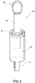
- a bistable shape memory alloy inertial actuator 10 in a different type of device is shown in figure 5 .
- a damper 50 has a stationary frame 51, with a stationary end 52 and a movable end 53 mounted on a shaft 54 sliding within frame 51 through a suitable aperture.
- the friction, and therefore the damping behavior encountered by the sliding shaft 54 in its vertical movement/oscillation is regulated by the bistable shape memory alloy inertial actuator 10 that in one of the two stable positions applies a higher compression on the movable shaft, increasing the frictional force applied and therefore increasing its stiffness.
- Figures 6 and 7 show a flow diverting valve 600 that has an inlet 601 and two outlets 602 and 602' selectively put in communication with inlet 601 by a bistable SMA inertial actuator 60, that comprises a SMA wire 62 operatively connected to an inertial mass 63 acting as shutter alternately for each of the two outlets.
- a first arm 66 links the inertial mass 63 to a pivot 65, sliding in the actuator body 61 and around which the SMA wire 62 is wound, and a second arm 67 links the inertial mass 63 to a fixed pivot 68, said arms 66, 67 being attached to the inertial mass 63 via a pivoting joining element 69.
- the second arm 67 is also provided with a slot 67a in which element 69 can slide, in order to allow the rotation of arm 67 around the fixed pivot 68, and the elastic locking force is provided by a biasing spring 64 acting on the sliding pivot 65 in the direction opposing the action of the SMA wire 62.
- the inertial mass 63 slides vertically thus opening one of the outlets 602 and 602', while acting as a shutter for the other outlet.
- bistable actuator of present invention is advantageously applied in smart locks such as padlocks.
- a SMA inertial bistable padlock is a device capable to overcome the limits of a standard SMA padlock by exploiting the advantages of the fast actuation to move one or more bistable mechanisms to lock/unlock the steel shackle of the padlock.
- SMA inertial mechanisms are not affected by the thermal self-actuation because the heating rate, provided by a flame or another external heating source directly in contact with the case of the padlock, is not fast enough to switch the state of the bistable mechanism.
- the heating rate provided by a flame or another external heating source directly in contact with the case of the padlock
- Padlock 700 comprises a solid body 701 retaining a sliding shackle 702, and a bistable inertial SMA actuator 10 comprising a locking pin 10' that engages a shackle recess 702', as shown in Fig.8 , while figure 9 shows the bistable inertial SMA actuator 10 in its second stable position with the locking pin 10' disengaged from recess 702' such that shackle 702 is free to slide out from the padlock body 701.
- the padlock 700 of figures 8 and 9 has the sliding shackle 702 that can be fully taken out from the padlock body 701, but an immediate variant (not shown) envisions a sliding shackle with legs of different length, so that a partial sliding of the shackle frees the shorter leg allowing the opening of the padlock while at the same time retaining the shackle by means of a suitable stopper on the longer leg.
- actuation time it is intended the time required to bring the shape memory alloy wire to a temperature where it is in its austenite phase, the so called Af temperature.
- some electronics circuitry may be associated with the SMA wire current supply such as a condenser, etc. even though in case of the narrower wires, such as wires with a diameter lower than 100 ⁇ m, even a battery can achieve such short actuation times.
- the actual parameter driving and determining the actuation time is the actuation pulse duration, i.e. the amount of time in which the SMA wire is supplied with current. Such pulse duration is much shorter than the actuation time, as defined above, which is a result of the pulse duration.
- the invention relates to a method to operate a bistable shape memory alloy inertial actuator, more specifically a method in which the actuation pulse is short, i.e. with a duration of the current applied to the shape memory alloy wire that is comprised between 0,1 ms and 50 ms, preferably between 1 ms and 25 ms.
- Ni-Ti based alloys such as Nitinol that may exhibit alternately superelastic wire behavior or shape memory alloy behavior according to its processing.
- the properties of Nitinol and methods allowing to achieve them are widely known to those skilled in the art, see e.g. the article " A Study of the Properties of a High Temperature Binary Nitinol Alloy Above and Below its Martensite to Austenite Transformation Temperature” by Dennis W. Norwich presented at the SMST 2010 conference.
- Nitinol may be used as such or its characteristics in terms of transition temperature may be tailored by adding elements such as Hf, Nb, Pt, Cu.
- the proper choice of material alloy and its characteristics are commonly known to a person skilled in the art, see for example: http://memry.com/nitinol-iq/nitinol-fundamentals/transformation-temperatures
- the shape memory alloy wires may be used "per se” or with a coating/sheath to improve their thermal management, i.e. their cooling after being actuated.
- the coating sheath may be uniform, such as described in the US patent 9.068.561 that teaches how to manage residual heat by resorting to an electrically insulating coating which is a heat conductor, while US patent 6.835.083 describes a shape memory alloy wire having an enclosing sheath capable to improve cooling after every actuation cycle.
- a coating with a suitable dispersion of phase changing materials such as described in WO 2019/003198 in the applicant's name, may be advantageously employed.
Landscapes
- Engineering & Computer Science (AREA)
- Chemical & Material Sciences (AREA)
- Combustion & Propulsion (AREA)
- Mechanical Engineering (AREA)
- General Engineering & Computer Science (AREA)
- Manufacturing & Machinery (AREA)
- Micromachines (AREA)
Claims (14)
- Bistabiler Trägheitsaktuator (10; 30; 60) aus einer Formgedächtnislegierung umfassend einen Körper (11; 31; 61), der mit einem oder mehreren Drähten (12; 32, 32', 32"; 62) aus einer Formgedächtnislegierung verbunden ist, die durch einen von einer elektrischen Schaltung erzeugten Stromimpuls betätigt werden können, wobei der eine oder die mehreren Drähte (12; 32, 32', 32"; 62) in operativem Kontakt mit einem Trägheitselement (13; 33; 63) stehen, das zwischen einer ersten stabilen Position und einer zweiten stabilen Position und umgekehrt bewegbar ist, wobei der Aktuator einer Verriegelungskraft mit einer elastischen Konstante K, ausgedrückt in g/mm (0,0098 N/mm), ausgesetzt ist,
dadurch gekennzeichnet, dass das Trägheitselement (13; 33; 63) zwischen der ersten stabilen Position und der zweiten stabilen Position und umgekehrt unter der gleichzeitigen Betätigung des einen oder der mehreren Drähte aus Formgedächtnislegierung (12; 32, 32', 32"; 62), die einen Durchmesser zwischen 0,025 und 0,5 mm aufweisen, bewegbar ist, und dass der Aktuator einen Parameter P aufweist, der definiert ist als der Kehrwert der elastischen Konstante, multipliziert mit dem Verhältnis zwischen der Masse M des Trägheitselements (13; 33; 63), ausgedrückt in Gramm, und der Gesamtquerschnittsfläche A, ausgedrückt in mm2 , der Drähte aus Formgedächtnislegierung (12; 32, 32', 32"; 62) im operativen Kontakt mit dem Trägheitselement (13; 33; 63), wobei der Parameter P=(1/K)∗(M/A) zwischen 15 und 750 mm-1 , vorzugsweise zwischen 25 und 500 mm-1 , liegt und dadurch, dass die elektrische Schaltung dazu ausgebildet ist, einen Stromimpuls mit einer Dauer zwischen 0,1 ms und 50 ms, vorzugsweise zwischen 1 ms und 25 ms, zu generieren. - Bistabiler Trägheitsaktuator (10; 30; 60) aus einer Formgedächtnislegierung nach Anspruch 1, wobei mindestens ein Element der elektrischen Schaltung, die den Stromimpuls erzeugt, auf dem Körper (11; 31; 61) angebracht ist.
- Bistabiler Trägheitsaktuator (10; 30; 60) aus einer Formgedächtnislegierung nach Anspruch 2, wobei das mindestens eine Element der elektrischen Schaltung ein Kondensator ist.
- Bistabiler Trägheitsaktuator (30) aus einer Formgedächtnislegierung nach einem der vorhergehenden Ansprüche, wobei er mehrere Drähte (12; 32, 32', 32"; 62) aus einer Formgedächtnislegierung umfasst, die parallel oder in Reihe geschaltet sind.
- Bistabiler Trägheitsaktuator (10; 30; 60) aus einer Formgedächtnislegierung nach einem der vorhergehenden Ansprüche, wobei die Verriegelungskraft mit der elastischen Konstante K durch ein elastisches Element (14; 64), das mit dem Aktuatorkörper (11; 61) verbunden ist, oder durch den Aktuatorkörper (31) selbst bereitgestellt wird.
- Bistabiler Trägheitsaktuator (10; 30) aus einer Formgedächtnislegierung nach einem der vorhergehenden Ansprüche, wobei der Aktuatorkörper (11; 31) einen Hauptteil mit einer Kreissegmentgeometrie aufweist, die vorzugsweise zwischen 2/3 und 5/6 eines Vollkreises umfasst.
- Bistabiler Trägheitsaktuator (10; 30) aus einer Formgedächtnislegierung nach Anspruch 6, wobei das Kreissegment einen Durchmesser zwischen 1 mm und 20 cm aufweist.
- Bistabiler Trägheitsaktuator (10; 30) aus einer Formgedächtnislegierung nach Anspruch 6 oder 7, wobei eine Mehrzahl an Scharnieren (15, 16, 16'; 36, 36') am Hauptteil des Aktuatorkörpers (11; 31) mit einer Kreissegmentgeometrie vorhanden sind.
- Bistabiler Trägheitsaktuator (10; 30) aus einer Formgedächtnislegierung nach Anspruch 8, wobei zwei Scharniere (16, 16'; 36, 36') zu Endteilen des Hauptteils des Aktuatorkörpers (11; 31) mit einer Kreissegmentgeometrie korrespondieren.
- Bistabiler Trägheitsaktuator (10; 30) aus einer Formgedächtnislegierung nach Anspruch 9, wobei das Trägheitselement (13; 33) mit dem Aktuatorkörper (11; 31) durch die Scharniere (16, 16'; 36, 36') korrespondierend zu den Endteilen des Hauptteils desselben mittels zweier Arme (17, 17'; 37, 37') gleicher Länge verbunden ist.
- Bistabiler Trägheitsaktuator (10) aus einer Formgedächtnislegierung nach Anspruch 10, wobei die Länge des Weges, der die Scharniere (16, 16'; 36, 36') entlang der beiden Arme (17, 17'; 37, 37') und durch das Trägheitselement (13; 33) verbindet, zwischen dem 1,1-und 3-fachen der Länge einer geraden, die Scharniere (16, 16'; 36, 36') verbindenden Linie beträgt.
- Verwendung eines bistabilen Trägheitsaktuators (10; 30; 60) aus einer Formgedächtnislegierung nach einem der Ansprüche 1 bis 11, um den Betrieb einer Vorrichtung zu steuern.
- Verwendung nach Anspruch 12, wobei es sich bei der Vorrichtung um einen Airbag (40), eine Dämpfer (50), ein Strömungsumlenkventil (600), einen elektrischen Schalter, ein Vorhängeschloss (700) oder ein Schloss handelt.
- Verfahren zum Betreiben eines bistabilen Trägheitsaktuators (10; 30; 60) aus einer Formgedächtnislegierung nach einem der Ansprüche 1 bis 11, wobei die Dauer des Stromimpulses für die Betätigung des einen oder der mehreren Drähte (12; 32, 32', 32"; 62) aus einer Formgedächtnislegierung zwischen 0,1 ms und 50 ms, vorzugsweise zwischen 1 ms und 25 ms liegt.
Applications Claiming Priority (2)
| Application Number | Priority Date | Filing Date | Title |
|---|---|---|---|
| IT202000006634 | 2020-03-30 | ||
| PCT/EP2021/057648 WO2021197980A1 (en) | 2020-03-30 | 2021-03-24 | Bistable shape memory alloy inertial actuator |
Publications (2)
| Publication Number | Publication Date |
|---|---|
| EP4065843A1 EP4065843A1 (de) | 2022-10-05 |
| EP4065843B1 true EP4065843B1 (de) | 2023-01-04 |
Family
ID=70805140
Family Applications (1)
| Application Number | Title | Priority Date | Filing Date |
|---|---|---|---|
| EP21714154.8A Active EP4065843B1 (de) | 2020-03-30 | 2021-03-24 | Bistabiler trägheitsaktuator aus formgedächtnislegierung |
Country Status (6)
| Country | Link |
|---|---|
| US (1) | US11788517B2 (de) |
| EP (1) | EP4065843B1 (de) |
| JP (1) | JP7561859B2 (de) |
| KR (1) | KR102711025B1 (de) |
| CN (1) | CN114930019B (de) |
| WO (1) | WO2021197980A1 (de) |
Families Citing this family (2)
| Publication number | Priority date | Publication date | Assignee | Title |
|---|---|---|---|---|
| EP4081711B1 (de) | 2021-03-02 | 2023-04-19 | Saes Getters S.p.A. | Asymmetrischer bistabiler trägheitsaktuator aus formgedächtnislegierung |
| EP4158194B1 (de) | 2021-08-13 | 2023-07-19 | Actuator Solutions GmbH | Aktuatorunterbaugruppe, die von formgedächtnislegierungsdrähten gesteuert wird, system mit einer vielzahl solcher unterbaugruppen und steuerungsverfahren für solch ein system |
Family Cites Families (19)
| Publication number | Priority date | Publication date | Assignee | Title |
|---|---|---|---|---|
| US4544988A (en) | 1983-10-27 | 1985-10-01 | Armada Corporation | Bistable shape memory effect thermal transducers |
| US4965545A (en) | 1989-08-09 | 1990-10-23 | Tini Alloy Company | Shape memory alloy rotary actuator |
| JPH07119619A (ja) * | 1993-10-07 | 1995-05-09 | Ricoh Co Ltd | 双方向機能部品及びそれを用いた通風口開閉装置 |
| US6049267A (en) * | 1997-06-12 | 2000-04-11 | Robertshaw Controls Company | Adaptive control module using shape memory alloy |
| US5977858A (en) | 1998-07-31 | 1999-11-02 | Hughes Electronics Corporation | Electro-thermal bi-stable actuator |
| WO2001099135A1 (de) | 2000-06-19 | 2001-12-27 | Tyco Electronics Amp Gmbh | Bistabiler elektrischer schalter und relais mit einem solchen |
| JP2003278051A (ja) | 2002-03-19 | 2003-10-02 | Inax Corp | 複数本の形状記憶ワイヤーを備えた面状体 |
| JP4233290B2 (ja) * | 2002-09-09 | 2009-03-04 | トキコーポレーション株式会社 | 形状記憶合金アクチュエータ |
| EP1552146B1 (de) * | 2002-10-09 | 2011-04-20 | Abbott Diabetes Care Inc. | Kraftstoffzufuhrvorrichtung, system und verfahren |
| ITTO20030045A1 (it) | 2003-01-28 | 2004-07-29 | Fiat Ricerche | Dispositivo attuatore a cavo flessibile a memoria di forma |
| ATE331138T1 (de) * | 2004-05-03 | 2006-07-15 | Fiat Ricerche | Bistabiler schalter mit formgedächtnismetall |
| ATE373795T1 (de) | 2004-10-28 | 2007-10-15 | Fiat Ricerche | Ventil |
| US8656713B2 (en) | 2009-10-28 | 2014-02-25 | GM Global Technology Operations LLC | Active material-based impulse actuators |
| JP5878869B2 (ja) | 2010-08-20 | 2016-03-08 | 株式会社青電舎 | 衝撃駆動型アクチュエータ |
| US8851443B2 (en) | 2010-12-15 | 2014-10-07 | Autosplice, Inc. | Memory alloy-actuated apparatus and methods for making and using the same |
| ITMI20111974A1 (it) | 2011-10-28 | 2013-04-29 | Getters Spa | Interruttore elettrico bistabile con attuatore a memoria di forma |
| ITMI20121705A1 (it) * | 2012-10-10 | 2014-04-11 | Getters Spa | Interruttore elettrico bistabile con attuatore a memoria di forma |
| ITMI20121988A1 (it) * | 2012-11-22 | 2014-05-23 | Getters Spa | Elemento attuatore con migliorata resistenza a fatica fatto di una lega a memoria di forma |
| IT201700073563A1 (it) | 2017-06-30 | 2018-12-30 | Getters Spa | Insiemi attuatori comprendenti fili in lega a memoria di forma e rivestimenti con particelle di materiali a cambiamento di fase |
-
2021
- 2021-03-24 EP EP21714154.8A patent/EP4065843B1/de active Active
- 2021-03-24 WO PCT/EP2021/057648 patent/WO2021197980A1/en not_active Ceased
- 2021-03-24 KR KR1020227023576A patent/KR102711025B1/ko active Active
- 2021-03-24 US US17/797,509 patent/US11788517B2/en active Active
- 2021-03-24 CN CN202180008067.8A patent/CN114930019B/zh active Active
- 2021-03-24 JP JP2022546098A patent/JP7561859B2/ja active Active
Also Published As
| Publication number | Publication date |
|---|---|
| JP7561859B2 (ja) | 2024-10-04 |
| JP2023520112A (ja) | 2023-05-16 |
| US20230054660A1 (en) | 2023-02-23 |
| CN114930019B (zh) | 2024-02-13 |
| WO2021197980A1 (en) | 2021-10-07 |
| US11788517B2 (en) | 2023-10-17 |
| CN114930019A (zh) | 2022-08-19 |
| EP4065843A1 (de) | 2022-10-05 |
| KR102711025B1 (ko) | 2024-09-27 |
| KR20220159949A (ko) | 2022-12-05 |
Similar Documents
| Publication | Publication Date | Title |
|---|---|---|
| US11788517B2 (en) | Bistable shape memory alloy inertial actuator | |
| US6691977B2 (en) | Shape memory alloy fuel injector | |
| US4945727A (en) | Hydraulic shape memory alloy actuator | |
| US20230124526A1 (en) | Multi-stable actuator | |
| WO2001097720A3 (en) | Bistable switch with shape memory metal | |
| US10273943B2 (en) | Heat sensitive actuator device | |
| US10871010B2 (en) | Swing type SMA actuator | |
| EP4081711B1 (de) | Asymmetrischer bistabiler trägheitsaktuator aus formgedächtnislegierung | |
| JP2023520112A5 (de) | ||
| GB2182747A (en) | Actuator device | |
| US20080258850A1 (en) | Switching Device Having an Electromagnetic Release | |
| KR100835609B1 (ko) | 반발형 회로차단기의 접촉자장치 | |
| DE102004056281A1 (de) | Schaltgerät mit einem elektromagnetischen Auslöser | |
| DE102004056283A1 (de) | Schaltgerät mit einem thermischen und elektromagnetischen Auslöser | |
| FI108090B (fi) | Parannettu käyttömekanismi sähkökytkintä, erityisesti piirikatkaisijaa tai virrankytkintä varten | |
| Patowari et al. | Comparative study of different micro-thermal actuators for micro-electro-mechanical-system application | |
| KR101034500B1 (ko) | 형상기억합금 액츄에이터 | |
| DE102004056279A1 (de) | Schaltgerät mit einem thermischen und elektromagnetischen Auslöser | |
| DE102004056282A1 (de) | Schaltgerät mit einem thermischen und elektromagnetischen Auslöser | |
| Chen et al. | Bi-directional movable latching structure using electrothermal V-beam actuators for optical switch application | |
| JPS6146475A (ja) | 形状記憶合金装置 | |
| EP1731700A2 (de) | Scharnier aus Formgedächtnismaterial | |
| JPH0574309A (ja) | 回路しや断器 | |
| Patowari et al. | COMPARATIVE STUDY OF DIFFERENT MICRO-THERMAL ACTUATORS FOR MEMS APPLICATION | |
| JPH0512969A (ja) | 回路しや断器 |
Legal Events
| Date | Code | Title | Description |
|---|---|---|---|
| STAA | Information on the status of an ep patent application or granted ep patent |
Free format text: STATUS: UNKNOWN |
|
| STAA | Information on the status of an ep patent application or granted ep patent |
Free format text: STATUS: THE INTERNATIONAL PUBLICATION HAS BEEN MADE |
|
| PUAI | Public reference made under article 153(3) epc to a published international application that has entered the european phase |
Free format text: ORIGINAL CODE: 0009012 |
|
| STAA | Information on the status of an ep patent application or granted ep patent |
Free format text: STATUS: REQUEST FOR EXAMINATION WAS MADE |
|
| GRAP | Despatch of communication of intention to grant a patent |
Free format text: ORIGINAL CODE: EPIDOSNIGR1 |
|
| STAA | Information on the status of an ep patent application or granted ep patent |
Free format text: STATUS: GRANT OF PATENT IS INTENDED |
|
| 17P | Request for examination filed |
Effective date: 20220630 |
|
| AK | Designated contracting states |
Kind code of ref document: A1 Designated state(s): AL AT BE BG CH CY CZ DE DK EE ES FI FR GB GR HR HU IE IS IT LI LT LU LV MC MK MT NL NO PL PT RO RS SE SI SK SM TR |
|
| GRAS | Grant fee paid |
Free format text: ORIGINAL CODE: EPIDOSNIGR3 |
|
| GRAA | (expected) grant |
Free format text: ORIGINAL CODE: 0009210 |
|
| STAA | Information on the status of an ep patent application or granted ep patent |
Free format text: STATUS: THE PATENT HAS BEEN GRANTED |
|
| AK | Designated contracting states |
Kind code of ref document: B1 Designated state(s): AL AT BE BG CH CY CZ DE DK EE ES FI FR GB GR HR HU IE IS IT LI LT LU LV MC MK MT NL NO PL PT RO RS SE SI SK SM TR |
|
| REG | Reference to a national code |
Ref country code: GB Ref legal event code: FG4D |
|
| REG | Reference to a national code |
Ref country code: CH Ref legal event code: EP |
|
| REG | Reference to a national code |
Ref country code: AT Ref legal event code: REF Ref document number: 1542113 Country of ref document: AT Kind code of ref document: T Effective date: 20230115 |
|
| REG | Reference to a national code |
Ref country code: DE Ref legal event code: R096 Ref document number: 602021001167 Country of ref document: DE |
|
| REG | Reference to a national code |
Ref country code: IE Ref legal event code: FG4D |
|
| REG | Reference to a national code |
Ref country code: LT Ref legal event code: MG9D |
|
| REG | Reference to a national code |
Ref country code: NL Ref legal event code: MP Effective date: 20230104 |
|
| REG | Reference to a national code |
Ref country code: AT Ref legal event code: MK05 Ref document number: 1542113 Country of ref document: AT Kind code of ref document: T Effective date: 20230104 |
|
| P01 | Opt-out of the competence of the unified patent court (upc) registered |
Effective date: 20230515 |
|
| PG25 | Lapsed in a contracting state [announced via postgrant information from national office to epo] |
Ref country code: NL Free format text: LAPSE BECAUSE OF FAILURE TO SUBMIT A TRANSLATION OF THE DESCRIPTION OR TO PAY THE FEE WITHIN THE PRESCRIBED TIME-LIMIT Effective date: 20230104 |
|
| PG25 | Lapsed in a contracting state [announced via postgrant information from national office to epo] |
Ref country code: RS Free format text: LAPSE BECAUSE OF FAILURE TO SUBMIT A TRANSLATION OF THE DESCRIPTION OR TO PAY THE FEE WITHIN THE PRESCRIBED TIME-LIMIT Effective date: 20230104 Ref country code: PT Free format text: LAPSE BECAUSE OF FAILURE TO SUBMIT A TRANSLATION OF THE DESCRIPTION OR TO PAY THE FEE WITHIN THE PRESCRIBED TIME-LIMIT Effective date: 20230504 Ref country code: NO Free format text: LAPSE BECAUSE OF FAILURE TO SUBMIT A TRANSLATION OF THE DESCRIPTION OR TO PAY THE FEE WITHIN THE PRESCRIBED TIME-LIMIT Effective date: 20230404 Ref country code: LV Free format text: LAPSE BECAUSE OF FAILURE TO SUBMIT A TRANSLATION OF THE DESCRIPTION OR TO PAY THE FEE WITHIN THE PRESCRIBED TIME-LIMIT Effective date: 20230104 Ref country code: LT Free format text: LAPSE BECAUSE OF FAILURE TO SUBMIT A TRANSLATION OF THE DESCRIPTION OR TO PAY THE FEE WITHIN THE PRESCRIBED TIME-LIMIT Effective date: 20230104 Ref country code: HR Free format text: LAPSE BECAUSE OF FAILURE TO SUBMIT A TRANSLATION OF THE DESCRIPTION OR TO PAY THE FEE WITHIN THE PRESCRIBED TIME-LIMIT Effective date: 20230104 Ref country code: ES Free format text: LAPSE BECAUSE OF FAILURE TO SUBMIT A TRANSLATION OF THE DESCRIPTION OR TO PAY THE FEE WITHIN THE PRESCRIBED TIME-LIMIT Effective date: 20230104 Ref country code: AT Free format text: LAPSE BECAUSE OF FAILURE TO SUBMIT A TRANSLATION OF THE DESCRIPTION OR TO PAY THE FEE WITHIN THE PRESCRIBED TIME-LIMIT Effective date: 20230104 |
|
| PG25 | Lapsed in a contracting state [announced via postgrant information from national office to epo] |
Ref country code: SE Free format text: LAPSE BECAUSE OF FAILURE TO SUBMIT A TRANSLATION OF THE DESCRIPTION OR TO PAY THE FEE WITHIN THE PRESCRIBED TIME-LIMIT Effective date: 20230104 Ref country code: PL Free format text: LAPSE BECAUSE OF FAILURE TO SUBMIT A TRANSLATION OF THE DESCRIPTION OR TO PAY THE FEE WITHIN THE PRESCRIBED TIME-LIMIT Effective date: 20230104 Ref country code: IS Free format text: LAPSE BECAUSE OF FAILURE TO SUBMIT A TRANSLATION OF THE DESCRIPTION OR TO PAY THE FEE WITHIN THE PRESCRIBED TIME-LIMIT Effective date: 20230504 Ref country code: GR Free format text: LAPSE BECAUSE OF FAILURE TO SUBMIT A TRANSLATION OF THE DESCRIPTION OR TO PAY THE FEE WITHIN THE PRESCRIBED TIME-LIMIT Effective date: 20230405 Ref country code: FI Free format text: LAPSE BECAUSE OF FAILURE TO SUBMIT A TRANSLATION OF THE DESCRIPTION OR TO PAY THE FEE WITHIN THE PRESCRIBED TIME-LIMIT Effective date: 20230104 |
|
| REG | Reference to a national code |
Ref country code: DE Ref legal event code: R097 Ref document number: 602021001167 Country of ref document: DE |
|
| PG25 | Lapsed in a contracting state [announced via postgrant information from national office to epo] |
Ref country code: SM Free format text: LAPSE BECAUSE OF FAILURE TO SUBMIT A TRANSLATION OF THE DESCRIPTION OR TO PAY THE FEE WITHIN THE PRESCRIBED TIME-LIMIT Effective date: 20230104 Ref country code: RO Free format text: LAPSE BECAUSE OF FAILURE TO SUBMIT A TRANSLATION OF THE DESCRIPTION OR TO PAY THE FEE WITHIN THE PRESCRIBED TIME-LIMIT Effective date: 20230104 Ref country code: MC Free format text: LAPSE BECAUSE OF FAILURE TO SUBMIT A TRANSLATION OF THE DESCRIPTION OR TO PAY THE FEE WITHIN THE PRESCRIBED TIME-LIMIT Effective date: 20230104 Ref country code: EE Free format text: LAPSE BECAUSE OF FAILURE TO SUBMIT A TRANSLATION OF THE DESCRIPTION OR TO PAY THE FEE WITHIN THE PRESCRIBED TIME-LIMIT Effective date: 20230104 Ref country code: DK Free format text: LAPSE BECAUSE OF FAILURE TO SUBMIT A TRANSLATION OF THE DESCRIPTION OR TO PAY THE FEE WITHIN THE PRESCRIBED TIME-LIMIT Effective date: 20230104 Ref country code: CZ Free format text: LAPSE BECAUSE OF FAILURE TO SUBMIT A TRANSLATION OF THE DESCRIPTION OR TO PAY THE FEE WITHIN THE PRESCRIBED TIME-LIMIT Effective date: 20230104 |
|
| PLBE | No opposition filed within time limit |
Free format text: ORIGINAL CODE: 0009261 |
|
| STAA | Information on the status of an ep patent application or granted ep patent |
Free format text: STATUS: NO OPPOSITION FILED WITHIN TIME LIMIT |
|
| PG25 | Lapsed in a contracting state [announced via postgrant information from national office to epo] |
Ref country code: SK Free format text: LAPSE BECAUSE OF FAILURE TO SUBMIT A TRANSLATION OF THE DESCRIPTION OR TO PAY THE FEE WITHIN THE PRESCRIBED TIME-LIMIT Effective date: 20230104 |
|
| REG | Reference to a national code |
Ref country code: BE Ref legal event code: MM Effective date: 20230331 |
|
| 26N | No opposition filed |
Effective date: 20231005 |
|
| PG25 | Lapsed in a contracting state [announced via postgrant information from national office to epo] |
Ref country code: LU Free format text: LAPSE BECAUSE OF NON-PAYMENT OF DUE FEES Effective date: 20230324 |
|
| REG | Reference to a national code |
Ref country code: IE Ref legal event code: MM4A |
|
| PG25 | Lapsed in a contracting state [announced via postgrant information from national office to epo] |
Ref country code: SI Free format text: LAPSE BECAUSE OF FAILURE TO SUBMIT A TRANSLATION OF THE DESCRIPTION OR TO PAY THE FEE WITHIN THE PRESCRIBED TIME-LIMIT Effective date: 20230104 Ref country code: IE Free format text: LAPSE BECAUSE OF NON-PAYMENT OF DUE FEES Effective date: 20230324 |
|
| PG25 | Lapsed in a contracting state [announced via postgrant information from national office to epo] |
Ref country code: BE Free format text: LAPSE BECAUSE OF NON-PAYMENT OF DUE FEES Effective date: 20230331 |
|
| REG | Reference to a national code |
Ref country code: CH Ref legal event code: PL |
|
| PG25 | Lapsed in a contracting state [announced via postgrant information from national office to epo] |
Ref country code: BG Free format text: LAPSE BECAUSE OF FAILURE TO SUBMIT A TRANSLATION OF THE DESCRIPTION OR TO PAY THE FEE WITHIN THE PRESCRIBED TIME-LIMIT Effective date: 20230104 |
|
| PG25 | Lapsed in a contracting state [announced via postgrant information from national office to epo] |
Ref country code: BG Free format text: LAPSE BECAUSE OF FAILURE TO SUBMIT A TRANSLATION OF THE DESCRIPTION OR TO PAY THE FEE WITHIN THE PRESCRIBED TIME-LIMIT Effective date: 20230104 |
|
| PG25 | Lapsed in a contracting state [announced via postgrant information from national office to epo] |
Ref country code: CH Free format text: LAPSE BECAUSE OF NON-PAYMENT OF DUE FEES Effective date: 20240331 |
|
| PGFP | Annual fee paid to national office [announced via postgrant information from national office to epo] |
Ref country code: IT Payment date: 20250331 Year of fee payment: 5 |
|
| PG25 | Lapsed in a contracting state [announced via postgrant information from national office to epo] |
Ref country code: CY Free format text: LAPSE BECAUSE OF FAILURE TO SUBMIT A TRANSLATION OF THE DESCRIPTION OR TO PAY THE FEE WITHIN THE PRESCRIBED TIME-LIMIT; INVALID AB INITIO Effective date: 20210324 |
|
| PG25 | Lapsed in a contracting state [announced via postgrant information from national office to epo] |
Ref country code: HU Free format text: LAPSE BECAUSE OF FAILURE TO SUBMIT A TRANSLATION OF THE DESCRIPTION OR TO PAY THE FEE WITHIN THE PRESCRIBED TIME-LIMIT; INVALID AB INITIO Effective date: 20210324 |
|
| PG25 | Lapsed in a contracting state [announced via postgrant information from national office to epo] |
Ref country code: TR Free format text: LAPSE BECAUSE OF FAILURE TO SUBMIT A TRANSLATION OF THE DESCRIPTION OR TO PAY THE FEE WITHIN THE PRESCRIBED TIME-LIMIT Effective date: 20230104 |
|
| PGFP | Annual fee paid to national office [announced via postgrant information from national office to epo] |
Ref country code: GB Payment date: 20260324 Year of fee payment: 6 |
|
| PGFP | Annual fee paid to national office [announced via postgrant information from national office to epo] |
Ref country code: DE Payment date: 20260320 Year of fee payment: 6 |
|
| PGFP | Annual fee paid to national office [announced via postgrant information from national office to epo] |
Ref country code: FR Payment date: 20260325 Year of fee payment: 6 |