EP4065321B1 - Cutting machine for transversely cutting logs of paper material - Google Patents
Cutting machine for transversely cutting logs of paper material Download PDFInfo
- Publication number
- EP4065321B1 EP4065321B1 EP20820572.4A EP20820572A EP4065321B1 EP 4065321 B1 EP4065321 B1 EP 4065321B1 EP 20820572 A EP20820572 A EP 20820572A EP 4065321 B1 EP4065321 B1 EP 4065321B1
- Authority
- EP
- European Patent Office
- Prior art keywords
- blade
- support
- cutting
- machine according
- axis
- Prior art date
- Legal status (The legal status is an assumption and is not a legal conclusion. Google has not performed a legal analysis and makes no representation as to the accuracy of the status listed.)
- Active
Links
Images


Classifications
-
- B—PERFORMING OPERATIONS; TRANSPORTING
- B26—HAND CUTTING TOOLS; CUTTING; SEVERING
- B26D—CUTTING; DETAILS COMMON TO MACHINES FOR PERFORATING, PUNCHING, CUTTING-OUT, STAMPING-OUT OR SEVERING
- B26D7/00—Details of apparatus for cutting, cutting-out, stamping-out, punching, perforating, or severing by means other than cutting
- B26D7/26—Means for mounting or adjusting the cutting member; Means for adjusting the stroke of the cutting member
- B26D7/2614—Means for mounting the cutting member
- B26D7/2621—Means for mounting the cutting member for circular cutters
-
- B—PERFORMING OPERATIONS; TRANSPORTING
- B23—MACHINE TOOLS; METAL-WORKING NOT OTHERWISE PROVIDED FOR
- B23D—PLANING; SLOTTING; SHEARING; BROACHING; SAWING; FILING; SCRAPING; LIKE OPERATIONS FOR WORKING METAL BY REMOVING MATERIAL, NOT OTHERWISE PROVIDED FOR
- B23D35/00—Tools for shearing machines or shearing devices; Holders or chucks for shearing tools
- B23D35/008—Means for changing the cutting members
-
- B—PERFORMING OPERATIONS; TRANSPORTING
- B23—MACHINE TOOLS; METAL-WORKING NOT OTHERWISE PROVIDED FOR
- B23Q—DETAILS, COMPONENTS, OR ACCESSORIES FOR MACHINE TOOLS, e.g. ARRANGEMENTS FOR COPYING OR CONTROLLING; MACHINE TOOLS IN GENERAL CHARACTERISED BY THE CONSTRUCTION OF PARTICULAR DETAILS OR COMPONENTS; COMBINATIONS OR ASSOCIATIONS OF METAL-WORKING MACHINES, NOT DIRECTED TO A PARTICULAR RESULT
- B23Q3/00—Devices holding, supporting, or positioning work or tools, of a kind normally removable from the machine
- B23Q3/155—Arrangements for automatic insertion or removal of tools, e.g. combined with manual handling
- B23Q3/157—Arrangements for automatic insertion or removal of tools, e.g. combined with manual handling of rotary tools
- B23Q3/15706—Arrangements for automatic insertion or removal of tools, e.g. combined with manual handling of rotary tools a single tool being inserted in a spindle directly from a storage device, i.e. without using transfer devices
-
- B—PERFORMING OPERATIONS; TRANSPORTING
- B23—MACHINE TOOLS; METAL-WORKING NOT OTHERWISE PROVIDED FOR
- B23Q—DETAILS, COMPONENTS, OR ACCESSORIES FOR MACHINE TOOLS, e.g. ARRANGEMENTS FOR COPYING OR CONTROLLING; MACHINE TOOLS IN GENERAL CHARACTERISED BY THE CONSTRUCTION OF PARTICULAR DETAILS OR COMPONENTS; COMBINATIONS OR ASSOCIATIONS OF METAL-WORKING MACHINES, NOT DIRECTED TO A PARTICULAR RESULT
- B23Q3/00—Devices holding, supporting, or positioning work or tools, of a kind normally removable from the machine
- B23Q3/155—Arrangements for automatic insertion or removal of tools, e.g. combined with manual handling
- B23Q3/157—Arrangements for automatic insertion or removal of tools, e.g. combined with manual handling of rotary tools
- B23Q3/15713—Arrangements for automatic insertion or removal of tools, e.g. combined with manual handling of rotary tools a transfer device taking a single tool from a storage device and inserting it in a spindle
-
- B—PERFORMING OPERATIONS; TRANSPORTING
- B26—HAND CUTTING TOOLS; CUTTING; SEVERING
- B26D—CUTTING; DETAILS COMMON TO MACHINES FOR PERFORATING, PUNCHING, CUTTING-OUT, STAMPING-OUT OR SEVERING
- B26D1/00—Cutting through work characterised by the nature or movement of the cutting member or particular materials not otherwise provided for; Apparatus or machines therefor; Cutting members therefor
- B26D1/01—Cutting through work characterised by the nature or movement of the cutting member or particular materials not otherwise provided for; Apparatus or machines therefor; Cutting members therefor involving a cutting member which does not travel with the work
- B26D1/12—Cutting through work characterised by the nature or movement of the cutting member or particular materials not otherwise provided for; Apparatus or machines therefor; Cutting members therefor involving a cutting member which does not travel with the work having a cutting member moving about an axis
- B26D1/14—Cutting through work characterised by the nature or movement of the cutting member or particular materials not otherwise provided for; Apparatus or machines therefor; Cutting members therefor involving a cutting member which does not travel with the work having a cutting member moving about an axis with a circular cutting member, e.g. disc cutter
- B26D1/157—Cutting through work characterised by the nature or movement of the cutting member or particular materials not otherwise provided for; Apparatus or machines therefor; Cutting members therefor involving a cutting member which does not travel with the work having a cutting member moving about an axis with a circular cutting member, e.g. disc cutter rotating about a movable axis
- B26D1/16—Cutting through work characterised by the nature or movement of the cutting member or particular materials not otherwise provided for; Apparatus or machines therefor; Cutting members therefor involving a cutting member which does not travel with the work having a cutting member moving about an axis with a circular cutting member, e.g. disc cutter rotating about a movable axis mounted on a movable arm or the like
-
- B—PERFORMING OPERATIONS; TRANSPORTING
- B26—HAND CUTTING TOOLS; CUTTING; SEVERING
- B26D—CUTTING; DETAILS COMMON TO MACHINES FOR PERFORATING, PUNCHING, CUTTING-OUT, STAMPING-OUT OR SEVERING
- B26D3/00—Cutting work characterised by the nature of the cut made; Apparatus therefor
- B26D3/16—Cutting rods or tubes transversely
-
- B—PERFORMING OPERATIONS; TRANSPORTING
- B26—HAND CUTTING TOOLS; CUTTING; SEVERING
- B26D—CUTTING; DETAILS COMMON TO MACHINES FOR PERFORATING, PUNCHING, CUTTING-OUT, STAMPING-OUT OR SEVERING
- B26D7/00—Details of apparatus for cutting, cutting-out, stamping-out, punching, perforating, or severing by means other than cutting
- B26D7/26—Means for mounting or adjusting the cutting member; Means for adjusting the stroke of the cutting member
- B26D7/2628—Means for adjusting the position of the cutting member
- B26D7/2635—Means for adjusting the position of the cutting member for circular cutters
-
- B—PERFORMING OPERATIONS; TRANSPORTING
- B26—HAND CUTTING TOOLS; CUTTING; SEVERING
- B26D—CUTTING; DETAILS COMMON TO MACHINES FOR PERFORATING, PUNCHING, CUTTING-OUT, STAMPING-OUT OR SEVERING
- B26D2210/00—Machines or methods used for cutting special materials
- B26D2210/11—Machines or methods used for cutting special materials for cutting web rolls
Definitions
- the present invention relates to a machine for the transversal cutting of logs made of paper material.
- the cutting-off machines for the transversal cutting of the logs of paper material comprise a plurality of longitudinal channels, in each of which a log is placed, and a cutting head. By coordinating the action of the cutting head with a mechanism for advancing the logs in the respective channels, each log is divided into a plurality of rolls of the desired length.
- the main purpose of the present invention is to propose a cutting-off machine for the transversal cutting of logs in which the replacement of worn blades is carried out by means of an automated procedure which allows to minimize the intervention of the operators and, at the same time, the time required for this operation.
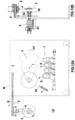
- a cutting-off machine (M) for the transversal cutting of the logs of paper material in accordance with the present invention comprises a plurality of channels (1) which define corresponding paths for advancing the logs (L), and a cutting head (CT) arranged to perform the transversal cutting of the logs (L) in order to obtain paper rolls having a predetermined length.
- the cutting head (CT) is mounted in a cutting station (T) of the cutting-off machine (M) and comprises a circular blade (2) that is oriented transversely to the channels (1) of the machine (M) and is driven by a corresponding electric motor which controls its rotation with a predetermined angular speed around its own rotation axis (x).
- the machine (M) can be equipped with elements for holding the logs, commonly called “pressers” (E), which hold the logs on the channels (1) during the execution of the cuts and release them immediately afterwards.
- pressers E
- the steps of handling, holding and transversal cutting of the logs, as well as the operation of the blade (2) and the arm (3), are known to those skilled in the art and therefore will not be described in further detail.
- the logs (L) can be moved along said channels (1) by means of pushers acting on the back of the logs (not shown in the drawings).
- a blade sharpening mechanism (2) known per se, can be associated with the cutting head (CT).
- CT cutting head
- the machine (M) is equipped with an automatic device for replacing worn blades.
- the blade (2) is constrained to the arm (3) by means of a joint (32) which has a rear side (320) constrained to the arm (3) and an opposite front side in which a threaded axial hole (321) is formed.
- the joint (32) is orthogonal to the arm (3) such that the blade (2) is spaced from the arm (3) when it is mounted on the latter.
- the pin (461) of a blade holder hub (46), further described below, is screwed in the threaded hole (321) formed on the front side of the joint (32), the blade holder hub being intended to constrain the blade (2) to the joint (32).
- a central part (322) of the joint (32) is connected to an electric motor carried by the arm (3) by means of a transmission belt (323).
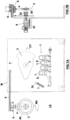
- the automatic device for replacing worn blades comprises a loading station (LS) in which a new blade (20) is arranged to replace a worn blade (2) mounted on the cutting head (CT) when the diameter of the worn blade reaches a minimum value that is deemed insufficient for the continuation of its use.
- the loading station (LS) is at a predetermined distance from the cutting head (CT).
- CT cutting head
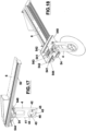
- a support (4) adapted to support, one at a time, both the new blade (20) and the worn blade (2) to be replaced.
- Said support (4) is mounted on a carriage (5) movable along a guide (6) which extends between the loading station (LS) and the cutting station (T).
- the support (4) consists of a metal plate, i.e. an element with a prevailing vertical development, and is rotatably constrained to the carriage (5), so that it can rotate on itself by 180 °, as further described below..
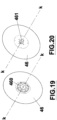
- the support (4) has, on its lower part (40), on both its faces (41, 42), a recess (43) in which a magnet (44) is positioned.
- the recess (43) and the magnet (44) have the shape of circular crowns coaxial to each other.
- Two positioning keys (45) are arranged on the recess (43) for facilitating the positioning of a metal blade-holder hub (46).
- the latter as shown in Fig.20 , on a respective rear face has a series of recesses (460) arranged circumferentially around its own axis (k) and, on the opposite front face, has a threaded pin (461) having a predefined length.
- the support (4) is mounted on a carriage (5) constrained to a guide (6) extending between the cutting station (T) and the loading station (LS), so that the support (4 ) can be moved bi-directionally between said stations (T, LS) along a path defined by the guide (6).
- the carriage (5) is connected to an actuator (50) which controls its movement along the guide (6).
- the support (4) is constrained to the carriage (5) by means of a rotary actuator (54) which allows the support (4) to be rotated around a vertical axis (z).
- said vertical axis (z) is a central axis of symmetry of the support (4).
- the rotary actuator (54) is integral with a horizontal plate (540) mounted sliding on two guides (541) formed on the lower edges of two corresponding side walls (542) of the carriage (5).
- the latter has an upper surface (543) which joins the upper edges of said side walls (542) forming a compartment in which a linear actuator (544) is housed.
- the mantle of the linear actuator (544) is fixed to the lower face of the upper surface of the carriage (5), while the stem is connected to the horizontal plate (540).
- the lower edges of the side walls of the carriage, as the guides (541) and the linear actuator (544), are oriented orthogonally to the guide (6) on which the carriage (5) is mounted.
- the support (4) can be moved both along the guide (6), both orthogonally to the guide (6), and in rotation around the vertical axis (z).
- the double arrow "M1" indicates the movement of the carriage (5) along the guide (6)
- the double arrow "M2” indicates the movement of the support (4) perpendicular to the guide (6)
- the double arrow "M3” indicates the rotation of the support (4) around the vertical axis (z).
- the machine (M) is provided with a device for blunting the blade (2).
- said device comprises a pneumatic actuator (7) on whose stem is mounted a pad (70) which, when brought into contact with the cutting edge of the blade (2) in use, blunt it, thus preventing the operator responsible for managing the blade change from injures when manipulating it.
- the pad (70) can be made of the same material of which the grinding wheels are normally made.
- the actuator (7) can be arranged as shown in the drawings, in such a way as not to interfere with the blade (2) during normal machine operation (M).
- the actuator (7) is arranged in a position suitably spaced from the cutting unit (CT) so that the pad (70) is brought into contact with the blade (2) only when the actuator (7) extracts its stem and moves the pad (70) towards the cutting edge of the blade (2).
- the blunt is determined by the contact of the pad (70) with the cutting edge of the blade (2) while the latter is being rotated.
- a gearmotor (8) is installed, equipped with a bush (80) with a horizontal axis which is coaxial to the joint (32) when the arm (3) is positioned in the blade replacement configuration as further described below.
- the gearmotor (8) is mounted on a slide (81) to be moved to and from the joint (32) by means of a respective actuator (82).
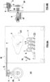
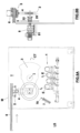
- the support (4) is waiting to receive a new blade intended to replace the blade (2) in use.
- an operator (not shown) in the station (LS) has inserted a new blade (20) on the hub (46) applied on the support (4).
- the blade (2) in use has reached the minimum diameter considered sufficient for its operational use and the arm (3) of the cutting unit (CT) has been positioned horizontally, so that the worn blade (2) is with its axis at the same height as the axis of the new blade (20), i.e. at the same height as the pin (461) of the hub (46) placed on the support (4).
- the blunting device (6, 60) is activated for blunting the cutting edge of the blade (2) while the latter rotates.
- the operator exits the station (LS) and the support (4) is rotated by 180 ° as schematically indicated by the arrow "M3" in Fig.3A .
- the support (4) has the free recess (43) (the other recess 43 is engaged by the hub 46 on which the new blade 20 has been mounted) facing the operator side of the loading station (LS), i.e. the side of said station where the operator previously mounted the new blade (20).
- the blunting device (6, 60) has been deactivated by returning the pad (60) to its initial position spaced from the blade (2) to be replaced as schematically indicated by the arrow "RW" in Fig.3A .
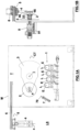
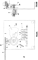
- the support (4) with the new blade (20) mounted on it, is brought in front of the arm (3) on which the blade to be replaced (2) is still applied, so that the axis (k) of the pin (461) is coaxial with the axis of the blade (2) to be replaced.
- the worn blade (2) remains coupled to the hub (46) which has been removed from the joint (32) and, since the hub (46) is magnetically hooked to the support (4), the worn blade is bound to the support (4) and then removed from the arm (3), as shown in Fig.6A and Fig.6B .
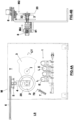
- the support (4) is returned to the station (LS), as shown in Fig.7A and Fig.7B .
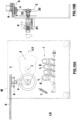
- the support (4) is rotated again by 180 °, as shown in Fig.8A and Fig.8B , so as to arrange the new blade (20) as it was previously arranged, i.e. facing the operator side.
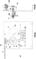
- the support (4) is brought in front of the arm (3) until the new blade (20) is positioned in correspondence with the cutting station (T).
- the support (4) is brought closer to the arm (3) so as to bring the pin (461) of the hub (46) of the new blade (20) in a coaxial position with the joint (32) and, while the belt (323) driven by the respective motor determines the rotation of the joint (32), for example counterclockwise, the pin (461) is screwed into the same joint (32) until the blade (20) come into contact with the arm (3); also in this phase. mechanical components of the cutting-off machine are used.
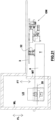
- Fig. 21 where the reference "GM" indicates a unit known per se including the actuators that control the rotation of the arm (3) and the blade (2) around their respective axes, is a schematic top view of the blade loading and unloading station (LS) and the cutting station (T). These stations are separated by a movable wall (MT). The station (LS) is accessed through a respective opening controlled by a further mobile wall (ML).
- the walls (MT, ML) are controlled in such a way that, when the operator is in the station (LS) the wall (MT) is closed. The latter is opened only if the presence of the operator is not detected in the station (LS). When the cutting machine (M) is in operation, both walls (MT, ML) are closed.
- the opening and closing of the walls (MT, ML) is controlled by a programmable unit according to criteria known per se to industrial automation technicians.
- the double arrows "FT" and "FL” in Fig.21 represent the movement of the walls "MT” and "ML” respectively.
- a machine (M) for the transversal cutting of logs of paper material in accordance with the present invention is a machine comprising
- the support (4) is shaped so that it can simultaneously hold a worn blade (2) and a new blade (20).
- the support (4) is always equipped with a hub (46) with a respective pin (461), the hub (46) being removably connected to the support (4).
- the hub (46) being removably connected to the support (4).
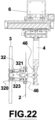
- Fig. 22 illustrates a configuration similar to that of Fig. 15 , in which the gearmotor (8) with the bushing (80) is not provided. In this case, the rotations that in the previous example are determined by the intervention of the gearmotor (8) are instead determined by the motor that drives the blade (2) through the belt (323).
Landscapes
- Engineering & Computer Science (AREA)
- Mechanical Engineering (AREA)
- Life Sciences & Earth Sciences (AREA)
- Forests & Forestry (AREA)
- Details Of Cutting Devices (AREA)
- Nonmetal Cutting Devices (AREA)
Priority Applications (1)
| Application Number | Priority Date | Filing Date | Title |
|---|---|---|---|
| RS20240890A RS65908B1 (sr) | 2019-11-25 | 2020-11-11 | Mašina za sečenje namenjena za poprečno sečenje koturova papirnog materijala |
Applications Claiming Priority (2)
| Application Number | Priority Date | Filing Date | Title |
|---|---|---|---|
| IT102019000022035A IT201900022035A1 (it) | 2019-11-25 | 2019-11-25 | Macchina per il taglio trasversale dei logs di materiale cartaceo |
| PCT/IT2020/050274 WO2021106019A1 (en) | 2019-11-25 | 2020-11-11 | Cutting machine for transversely cutting logs of paper material |
Publications (2)
| Publication Number | Publication Date |
|---|---|
| EP4065321A1 EP4065321A1 (en) | 2022-10-05 |
| EP4065321B1 true EP4065321B1 (en) | 2024-07-24 |
Family
ID=69904034
Family Applications (1)
| Application Number | Title | Priority Date | Filing Date |
|---|---|---|---|
| EP20820572.4A Active EP4065321B1 (en) | 2019-11-25 | 2020-11-11 | Cutting machine for transversely cutting logs of paper material |
Country Status (11)
| Country | Link |
|---|---|
| US (1) | US20220297334A1 (pl) |
| EP (1) | EP4065321B1 (pl) |
| JP (1) | JP7509874B2 (pl) |
| CN (1) | CN114728427B (pl) |
| BR (1) | BR112022007793A2 (pl) |
| ES (1) | ES2986014T3 (pl) |
| FI (1) | FI4065321T3 (pl) |
| IT (1) | IT201900022035A1 (pl) |
| PL (1) | PL4065321T3 (pl) |
| RS (1) | RS65908B1 (pl) |
| WO (1) | WO2021106019A1 (pl) |
Families Citing this family (2)
| Publication number | Priority date | Publication date | Assignee | Title |
|---|---|---|---|---|
| US20230150077A1 (en) * | 2021-11-18 | 2023-05-18 | Paper Converting Machine Company | Log Cutting Saw With Automatic Blade Changer and Method of Using Same |
| IT202300006105A1 (it) | 2023-03-29 | 2024-09-29 | Paper Converting Machine Company S P A | Macchina per il taglio di log di materiale nastriforme provvista di un dispositivo per la sostituzione automatica della lama di taglio |
Family Cites Families (19)
| Publication number | Priority date | Publication date | Assignee | Title |
|---|---|---|---|---|
| FR2001572A6 (pl) * | 1968-02-08 | 1969-09-26 | Schloemann Ag | |
| DE3234675A1 (de) * | 1982-09-18 | 1984-03-22 | Ex-Cell-O Gmbh, 7332 Eislingen | Verriegelungsvorrichtung fuer werkzeuge in werkzeugmagazinen |
| JPH0238327B2 (ja) * | 1983-04-28 | 1990-08-30 | Mitsubishi Heavy Ind Ltd | Saidotorimanohataisochi |
| DE3326292C1 (de) | 1983-07-21 | 1985-01-31 | Hans Kaltenbach Maschinenfabrik GmbH & Co, 7850 Lörrach | Vorrichtung zum Wechseln des Sägeblattes an einer Kreissägemaschine |
| ATE115030T1 (de) * | 1986-11-04 | 1994-12-15 | Fritz Kruesi Maschinenbau | Vorrichtung zum bearbeiten eines werkstückes aus holz, insbesondere von holzbalken. |
| IT1247330B (it) | 1991-04-03 | 1994-12-12 | Perini Fabio Spa | Macchina troncatrice per il taglio di rotoli di materiale nastriforme. |
| DE9113684U1 (de) * | 1991-11-02 | 1991-12-19 | Keuro Maschinenbau Gmbh & Co Kg, 7590 Achern | Vorrichtung zum Wechseln des Sägeblattes an einer Kreissägemaschine |
| DE9413771U1 (de) * | 1994-08-26 | 1994-10-13 | Man Roland Druckmaschinen Ag, 63069 Offenbach | Längsschneideinrichtung für Bahnen mit zugehöriger Messerwechselvorrichtung |
| IT1279651B1 (it) * | 1995-10-11 | 1997-12-16 | Selco Srl | Macchina sezionatrice di pezzi. |
| JP3059439B1 (ja) * | 1999-10-18 | 2000-07-04 | 川之江造機株式会社 | ログペ―パ―切断装置の丸鋸高さ調節装置 |
| IT1308313B1 (it) | 1999-11-17 | 2001-12-10 | Perini Fabio Spa | Dispositivo di affilatura per utensili ruotanti di taglio e macchinaimpiegante detto dispositivo. |
| IT1314595B1 (it) * | 2000-03-28 | 2002-12-20 | Perini Fabio Spa | Troncatrice multipla per prodotti in materiale nastriforme con unazona di affilatura delle lame separata dalla zona di taglio |
| DE10125923C2 (de) * | 2001-05-21 | 2003-04-30 | Pallmann Kg Maschf | Verfahren, Anordnung und Magazin zum selbsttätigen Auswechseln der Messereinheiten eines Messerrings eines Messerringzerspaners |
| IT1391656B1 (it) * | 2008-11-07 | 2012-01-17 | Polimeri Europa Spa | Lame per granulatore ad alta resistenza all'usura e relativo metodo di affilatura |
| CN101850558B (zh) * | 2010-01-28 | 2012-05-02 | 苏州市乾丰造纸机械制造有限公司 | 一种盘纸分切机 |
| JP6267043B2 (ja) | 2014-04-02 | 2018-01-24 | 株式会社ディスコ | ブレード装着工具 |
| WO2016030124A1 (en) | 2014-08-29 | 2016-03-03 | Fabio Perini S.P.A. | Method and machine for cutting logs of wound web material |
| CN107107363B (zh) * | 2014-08-29 | 2020-05-05 | 法比奥·泼尼股份公司 | 用于切割幅材卷的切割机和方法 |
| JP6560714B2 (ja) * | 2017-06-26 | 2019-08-14 | Towa株式会社 | ブレード交換機構、切断装置およびブレード交換方法 |
-
2019
- 2019-11-25 IT IT102019000022035A patent/IT201900022035A1/it unknown
-
2020
- 2020-11-11 CN CN202080078978.3A patent/CN114728427B/zh active Active
- 2020-11-11 FI FIEP20820572.4T patent/FI4065321T3/fi active
- 2020-11-11 EP EP20820572.4A patent/EP4065321B1/en active Active
- 2020-11-11 ES ES20820572T patent/ES2986014T3/es active Active
- 2020-11-11 JP JP2022528253A patent/JP7509874B2/ja active Active
- 2020-11-11 US US17/769,889 patent/US20220297334A1/en active Pending
- 2020-11-11 WO PCT/IT2020/050274 patent/WO2021106019A1/en not_active Ceased
- 2020-11-11 PL PL20820572.4T patent/PL4065321T3/pl unknown
- 2020-11-11 BR BR112022007793A patent/BR112022007793A2/pt unknown
- 2020-11-11 RS RS20240890A patent/RS65908B1/sr unknown
Also Published As
| Publication number | Publication date |
|---|---|
| WO2021106019A1 (en) | 2021-06-03 |
| PL4065321T3 (pl) | 2024-10-21 |
| CN114728427B (zh) | 2023-06-27 |
| RS65908B1 (sr) | 2024-10-31 |
| US20220297334A1 (en) | 2022-09-22 |
| EP4065321A1 (en) | 2022-10-05 |
| FI4065321T3 (fi) | 2024-08-14 |
| JP2023502648A (ja) | 2023-01-25 |
| IT201900022035A1 (it) | 2021-05-25 |
| ES2986014T3 (es) | 2024-11-08 |
| CN114728427A (zh) | 2022-07-08 |
| BR112022007793A2 (pt) | 2022-07-05 |
| JP7509874B2 (ja) | 2024-07-02 |
Similar Documents
| Publication | Publication Date | Title |
|---|---|---|
| EP4065321B1 (en) | Cutting machine for transversely cutting logs of paper material | |
| EP3479975B1 (en) | Method and machine for cutting logs of wound web material | |
| EP2097231B1 (en) | Machine for cutting paper logs | |
| US8863628B2 (en) | Apparatus for trimming paper rolls or logs and an operating method for treating the logs | |
| US4292867A (en) | Apparatus and method for slitting elongated rolls of material | |
| EP3077157B1 (en) | Device for sharpening blades | |
| JPS62259960A (ja) | 予含浸処理した繊維スライバを載置するための装置 | |
| EP4065320B1 (en) | Cutting machine for transversely cutting logs of paper | |
| EP1491102B1 (en) | Tobacco shredding machine | |
| US20240109218A1 (en) | Cutting-off machine for the transversal cutting of logs of paper material | |
| US20220016798A1 (en) | Cutting machine for paper rolls with a sharpening device | |
| EP4565397B1 (en) | Interfolding machine and method for varying a length of sheet articles produced by the interfolding machine | |
| EP4393324A1 (en) | Machine for manufacturing rods | |
| JPH07156099A (ja) | 紙管切断機 | |
| WO2020250256A1 (en) | Cutting machine for paper material logs with a sharpening unit |
Legal Events
| Date | Code | Title | Description |
|---|---|---|---|
| STAA | Information on the status of an ep patent application or granted ep patent |
Free format text: STATUS: UNKNOWN |
|
| STAA | Information on the status of an ep patent application or granted ep patent |
Free format text: STATUS: THE INTERNATIONAL PUBLICATION HAS BEEN MADE |
|
| PUAI | Public reference made under article 153(3) epc to a published international application that has entered the european phase |
Free format text: ORIGINAL CODE: 0009012 |
|
| STAA | Information on the status of an ep patent application or granted ep patent |
Free format text: STATUS: REQUEST FOR EXAMINATION WAS MADE |
|
| 17P | Request for examination filed |
Effective date: 20220413 |
|
| AK | Designated contracting states |
Kind code of ref document: A1 Designated state(s): AL AT BE BG CH CY CZ DE DK EE ES FI FR GB GR HR HU IE IS IT LI LT LU LV MC MK MT NL NO PL PT RO RS SE SI SK SM TR |
|
| DAV | Request for validation of the european patent (deleted) | ||
| DAX | Request for extension of the european patent (deleted) | ||
| STAA | Information on the status of an ep patent application or granted ep patent |
Free format text: STATUS: EXAMINATION IS IN PROGRESS |
|
| 17Q | First examination report despatched |
Effective date: 20230707 |
|
| GRAP | Despatch of communication of intention to grant a patent |
Free format text: ORIGINAL CODE: EPIDOSNIGR1 |
|
| STAA | Information on the status of an ep patent application or granted ep patent |
Free format text: STATUS: GRANT OF PATENT IS INTENDED |
|
| INTG | Intention to grant announced |
Effective date: 20240305 |
|
| RAP3 | Party data changed (applicant data changed or rights of an application transferred) |
Owner name: FUTURA S.P.A. |
|
| GRAS | Grant fee paid |
Free format text: ORIGINAL CODE: EPIDOSNIGR3 |
|
| GRAA | (expected) grant |
Free format text: ORIGINAL CODE: 0009210 |
|
| STAA | Information on the status of an ep patent application or granted ep patent |
Free format text: STATUS: THE PATENT HAS BEEN GRANTED |
|
| AK | Designated contracting states |
Kind code of ref document: B1 Designated state(s): AL AT BE BG CH CY CZ DE DK EE ES FI FR GB GR HR HU IE IS IT LI LT LU LV MC MK MT NL NO PL PT RO RS SE SI SK SM TR |
|
| REG | Reference to a national code |
Ref country code: GB Ref legal event code: FG4D |
|
| REG | Reference to a national code |
Ref country code: CH Ref legal event code: EP |
|
| REG | Reference to a national code |
Ref country code: FI Ref legal event code: FGE Ref country code: IE Ref legal event code: FG4D Ref country code: DE Ref legal event code: R096 Ref document number: 602020034586 Country of ref document: DE |
|
| REG | Reference to a national code |
Ref country code: SE Ref legal event code: TRGR |
|
| REG | Reference to a national code |
Ref country code: ES Ref legal event code: FG2A Ref document number: 2986014 Country of ref document: ES Kind code of ref document: T3 Effective date: 20241108 |
|
| REG | Reference to a national code |
Ref country code: LT Ref legal event code: MG9D |
|
| REG | Reference to a national code |
Ref country code: NL Ref legal event code: MP Effective date: 20240724 |
|
| PG25 | Lapsed in a contracting state [announced via postgrant information from national office to epo] |
Ref country code: PT Free format text: LAPSE BECAUSE OF FAILURE TO SUBMIT A TRANSLATION OF THE DESCRIPTION OR TO PAY THE FEE WITHIN THE PRESCRIBED TIME-LIMIT Effective date: 20241125 |
|
| REG | Reference to a national code |
Ref country code: AT Ref legal event code: MK05 Ref document number: 1705911 Country of ref document: AT Kind code of ref document: T Effective date: 20240724 |
|
| PG25 | Lapsed in a contracting state [announced via postgrant information from national office to epo] |
Ref country code: NL Free format text: LAPSE BECAUSE OF FAILURE TO SUBMIT A TRANSLATION OF THE DESCRIPTION OR TO PAY THE FEE WITHIN THE PRESCRIBED TIME-LIMIT Effective date: 20240724 |
|
| PG25 | Lapsed in a contracting state [announced via postgrant information from national office to epo] |
Ref country code: PT Free format text: LAPSE BECAUSE OF FAILURE TO SUBMIT A TRANSLATION OF THE DESCRIPTION OR TO PAY THE FEE WITHIN THE PRESCRIBED TIME-LIMIT Effective date: 20241125 Ref country code: NL Free format text: LAPSE BECAUSE OF FAILURE TO SUBMIT A TRANSLATION OF THE DESCRIPTION OR TO PAY THE FEE WITHIN THE PRESCRIBED TIME-LIMIT Effective date: 20240724 |
|
| PG25 | Lapsed in a contracting state [announced via postgrant information from national office to epo] |
Ref country code: NO Free format text: LAPSE BECAUSE OF FAILURE TO SUBMIT A TRANSLATION OF THE DESCRIPTION OR TO PAY THE FEE WITHIN THE PRESCRIBED TIME-LIMIT Effective date: 20241024 |
|
| PG25 | Lapsed in a contracting state [announced via postgrant information from national office to epo] |
Ref country code: GR Free format text: LAPSE BECAUSE OF FAILURE TO SUBMIT A TRANSLATION OF THE DESCRIPTION OR TO PAY THE FEE WITHIN THE PRESCRIBED TIME-LIMIT Effective date: 20241025 |
|
| PG25 | Lapsed in a contracting state [announced via postgrant information from national office to epo] |
Ref country code: BG Free format text: LAPSE BECAUSE OF FAILURE TO SUBMIT A TRANSLATION OF THE DESCRIPTION OR TO PAY THE FEE WITHIN THE PRESCRIBED TIME-LIMIT Effective date: 20240724 |
|
| PG25 | Lapsed in a contracting state [announced via postgrant information from national office to epo] |
Ref country code: LV Free format text: LAPSE BECAUSE OF FAILURE TO SUBMIT A TRANSLATION OF THE DESCRIPTION OR TO PAY THE FEE WITHIN THE PRESCRIBED TIME-LIMIT Effective date: 20240724 |
|
| PG25 | Lapsed in a contracting state [announced via postgrant information from national office to epo] |
Ref country code: AT Free format text: LAPSE BECAUSE OF FAILURE TO SUBMIT A TRANSLATION OF THE DESCRIPTION OR TO PAY THE FEE WITHIN THE PRESCRIBED TIME-LIMIT Effective date: 20240724 Ref country code: IS Free format text: LAPSE BECAUSE OF FAILURE TO SUBMIT A TRANSLATION OF THE DESCRIPTION OR TO PAY THE FEE WITHIN THE PRESCRIBED TIME-LIMIT Effective date: 20241124 |
|
| PG25 | Lapsed in a contracting state [announced via postgrant information from national office to epo] |
Ref country code: HR Free format text: LAPSE BECAUSE OF FAILURE TO SUBMIT A TRANSLATION OF THE DESCRIPTION OR TO PAY THE FEE WITHIN THE PRESCRIBED TIME-LIMIT Effective date: 20240724 |
|
| PG25 | Lapsed in a contracting state [announced via postgrant information from national office to epo] |
Ref country code: NO Free format text: LAPSE BECAUSE OF FAILURE TO SUBMIT A TRANSLATION OF THE DESCRIPTION OR TO PAY THE FEE WITHIN THE PRESCRIBED TIME-LIMIT Effective date: 20241024 Ref country code: LV Free format text: LAPSE BECAUSE OF FAILURE TO SUBMIT A TRANSLATION OF THE DESCRIPTION OR TO PAY THE FEE WITHIN THE PRESCRIBED TIME-LIMIT Effective date: 20240724 Ref country code: IS Free format text: LAPSE BECAUSE OF FAILURE TO SUBMIT A TRANSLATION OF THE DESCRIPTION OR TO PAY THE FEE WITHIN THE PRESCRIBED TIME-LIMIT Effective date: 20241124 Ref country code: HR Free format text: LAPSE BECAUSE OF FAILURE TO SUBMIT A TRANSLATION OF THE DESCRIPTION OR TO PAY THE FEE WITHIN THE PRESCRIBED TIME-LIMIT Effective date: 20240724 Ref country code: GR Free format text: LAPSE BECAUSE OF FAILURE TO SUBMIT A TRANSLATION OF THE DESCRIPTION OR TO PAY THE FEE WITHIN THE PRESCRIBED TIME-LIMIT Effective date: 20241025 Ref country code: BG Free format text: LAPSE BECAUSE OF FAILURE TO SUBMIT A TRANSLATION OF THE DESCRIPTION OR TO PAY THE FEE WITHIN THE PRESCRIBED TIME-LIMIT Effective date: 20240724 Ref country code: AT Free format text: LAPSE BECAUSE OF FAILURE TO SUBMIT A TRANSLATION OF THE DESCRIPTION OR TO PAY THE FEE WITHIN THE PRESCRIBED TIME-LIMIT Effective date: 20240724 |
|
| PG25 | Lapsed in a contracting state [announced via postgrant information from national office to epo] |
Ref country code: DK Free format text: LAPSE BECAUSE OF FAILURE TO SUBMIT A TRANSLATION OF THE DESCRIPTION OR TO PAY THE FEE WITHIN THE PRESCRIBED TIME-LIMIT Effective date: 20240724 Ref country code: SM Free format text: LAPSE BECAUSE OF FAILURE TO SUBMIT A TRANSLATION OF THE DESCRIPTION OR TO PAY THE FEE WITHIN THE PRESCRIBED TIME-LIMIT Effective date: 20240724 |
|
| PG25 | Lapsed in a contracting state [announced via postgrant information from national office to epo] |
Ref country code: EE Free format text: LAPSE BECAUSE OF FAILURE TO SUBMIT A TRANSLATION OF THE DESCRIPTION OR TO PAY THE FEE WITHIN THE PRESCRIBED TIME-LIMIT Effective date: 20240724 |
|
| PG25 | Lapsed in a contracting state [announced via postgrant information from national office to epo] |
Ref country code: CZ Free format text: LAPSE BECAUSE OF FAILURE TO SUBMIT A TRANSLATION OF THE DESCRIPTION OR TO PAY THE FEE WITHIN THE PRESCRIBED TIME-LIMIT Effective date: 20240724 |
|
| REG | Reference to a national code |
Ref country code: DE Ref legal event code: R097 Ref document number: 602020034586 Country of ref document: DE |
|
| PG25 | Lapsed in a contracting state [announced via postgrant information from national office to epo] |
Ref country code: SK Free format text: LAPSE BECAUSE OF FAILURE TO SUBMIT A TRANSLATION OF THE DESCRIPTION OR TO PAY THE FEE WITHIN THE PRESCRIBED TIME-LIMIT Effective date: 20240724 |
|
| PLBE | No opposition filed within time limit |
Free format text: ORIGINAL CODE: 0009261 |
|
| STAA | Information on the status of an ep patent application or granted ep patent |
Free format text: STATUS: NO OPPOSITION FILED WITHIN TIME LIMIT |
|
| REG | Reference to a national code |
Ref country code: CH Ref legal event code: PL |
|
| 26N | No opposition filed |
Effective date: 20250425 |
|
| PG25 | Lapsed in a contracting state [announced via postgrant information from national office to epo] |
Ref country code: MC Free format text: LAPSE BECAUSE OF FAILURE TO SUBMIT A TRANSLATION OF THE DESCRIPTION OR TO PAY THE FEE WITHIN THE PRESCRIBED TIME-LIMIT Effective date: 20240724 |
|
| PG25 | Lapsed in a contracting state [announced via postgrant information from national office to epo] |
Ref country code: LU Free format text: LAPSE BECAUSE OF NON-PAYMENT OF DUE FEES Effective date: 20241111 |
|
| REG | Reference to a national code |
Ref country code: CH Ref legal event code: PL |
|
| PG25 | Lapsed in a contracting state [announced via postgrant information from national office to epo] |
Ref country code: CH Free format text: LAPSE BECAUSE OF NON-PAYMENT OF DUE FEES Effective date: 20241130 |
|
| REG | Reference to a national code |
Ref country code: BE Ref legal event code: MM Effective date: 20241130 |
|
| PG25 | Lapsed in a contracting state [announced via postgrant information from national office to epo] |
Ref country code: BE Free format text: LAPSE BECAUSE OF NON-PAYMENT OF DUE FEES Effective date: 20241130 |
|
| PG25 | Lapsed in a contracting state [announced via postgrant information from national office to epo] |
Ref country code: IE Free format text: LAPSE BECAUSE OF NON-PAYMENT OF DUE FEES Effective date: 20241111 |
|
| PGFP | Annual fee paid to national office [announced via postgrant information from national office to epo] |
Ref country code: DE Payment date: 20251119 Year of fee payment: 6 |
|
| PGFP | Annual fee paid to national office [announced via postgrant information from national office to epo] |
Ref country code: GB Payment date: 20251121 Year of fee payment: 6 |
|
| PGFP | Annual fee paid to national office [announced via postgrant information from national office to epo] |
Ref country code: FI Payment date: 20251125 Year of fee payment: 6 Ref country code: IT Payment date: 20251020 Year of fee payment: 6 |
|
| PGFP | Annual fee paid to national office [announced via postgrant information from national office to epo] |
Ref country code: FR Payment date: 20251126 Year of fee payment: 6 |
|
| PGFP | Annual fee paid to national office [announced via postgrant information from national office to epo] |
Ref country code: TR Payment date: 20251104 Year of fee payment: 6 |
|
| PGFP | Annual fee paid to national office [announced via postgrant information from national office to epo] |
Ref country code: SE Payment date: 20251119 Year of fee payment: 6 |
|
| PGFP | Annual fee paid to national office [announced via postgrant information from national office to epo] |
Ref country code: PL Payment date: 20251106 Year of fee payment: 6 |
|
| PGFP | Annual fee paid to national office [announced via postgrant information from national office to epo] |
Ref country code: RO Payment date: 20251103 Year of fee payment: 6 |
|
| PGFP | Annual fee paid to national office [announced via postgrant information from national office to epo] |
Ref country code: RS Payment date: 20251031 Year of fee payment: 6 |
|
| PGFP | Annual fee paid to national office [announced via postgrant information from national office to epo] |
Ref country code: ES Payment date: 20251229 Year of fee payment: 6 |
|
| PG25 | Lapsed in a contracting state [announced via postgrant information from national office to epo] |
Ref country code: HU Free format text: LAPSE BECAUSE OF FAILURE TO SUBMIT A TRANSLATION OF THE DESCRIPTION OR TO PAY THE FEE WITHIN THE PRESCRIBED TIME-LIMIT; INVALID AB INITIO Effective date: 20201111 |
|
| PG25 | Lapsed in a contracting state [announced via postgrant information from national office to epo] |
Ref country code: CY Free format text: LAPSE BECAUSE OF FAILURE TO SUBMIT A TRANSLATION OF THE DESCRIPTION OR TO PAY THE FEE WITHIN THE PRESCRIBED TIME-LIMIT; INVALID AB INITIO Effective date: 20201111 |