EP4065296B1 - Heissprägewerkzeuganordnung und verfahren zur herstellung eines teils mit massgeschneiderten härteeigenschaften - Google Patents
Heissprägewerkzeuganordnung und verfahren zur herstellung eines teils mit massgeschneiderten härteeigenschaften Download PDFInfo
- Publication number
- EP4065296B1 EP4065296B1 EP20891842.5A EP20891842A EP4065296B1 EP 4065296 B1 EP4065296 B1 EP 4065296B1 EP 20891842 A EP20891842 A EP 20891842A EP 4065296 B1 EP4065296 B1 EP 4065296B1
- Authority
- EP
- European Patent Office
- Prior art keywords
- die
- annealing
- shaped part
- hot
- forming die
- Prior art date
- Legal status (The legal status is an assumption and is not a legal conclusion. Google has not performed a legal analysis and makes no representation as to the accuracy of the status listed.)
- Active
Links
Images




Classifications
-
- C—CHEMISTRY; METALLURGY
- C21—METALLURGY OF IRON
- C21D—MODIFYING THE PHYSICAL STRUCTURE OF FERROUS METALS; GENERAL DEVICES FOR HEAT TREATMENT OF FERROUS OR NON-FERROUS METALS OR ALLOYS; MAKING METAL MALLEABLE, e.g. BY DECARBURISATION OR TEMPERING
- C21D1/00—General methods or devices for heat treatment, e.g. annealing, hardening, quenching or tempering
- C21D1/62—Quenching devices
- C21D1/673—Quenching devices for die quenching
-
- B—PERFORMING OPERATIONS; TRANSPORTING
- B21—MECHANICAL METAL-WORKING WITHOUT ESSENTIALLY REMOVING MATERIAL; PUNCHING METAL
- B21D—WORKING OR PROCESSING OF SHEET METAL OR METAL TUBES, RODS OR PROFILES WITHOUT ESSENTIALLY REMOVING MATERIAL; PUNCHING METAL
- B21D22/00—Shaping without cutting, by stamping, spinning, or deep-drawing
- B21D22/02—Stamping using rigid devices or tools
- B21D22/022—Stamping using rigid devices or tools by heating the blank or stamping associated with heat treatment
-
- B—PERFORMING OPERATIONS; TRANSPORTING
- B21—MECHANICAL METAL-WORKING WITHOUT ESSENTIALLY REMOVING MATERIAL; PUNCHING METAL
- B21D—WORKING OR PROCESSING OF SHEET METAL OR METAL TUBES, RODS OR PROFILES WITHOUT ESSENTIALLY REMOVING MATERIAL; PUNCHING METAL
- B21D22/00—Shaping without cutting, by stamping, spinning, or deep-drawing
- B21D22/20—Deep-drawing
- B21D22/208—Deep-drawing by heating the blank or deep-drawing associated with heat treatment
-
- B—PERFORMING OPERATIONS; TRANSPORTING
- B21—MECHANICAL METAL-WORKING WITHOUT ESSENTIALLY REMOVING MATERIAL; PUNCHING METAL
- B21D—WORKING OR PROCESSING OF SHEET METAL OR METAL TUBES, RODS OR PROFILES WITHOUT ESSENTIALLY REMOVING MATERIAL; PUNCHING METAL
- B21D37/00—Tools as parts of machines covered by this subclass
- B21D37/08—Dies with different parts for several steps in a process
-
- B—PERFORMING OPERATIONS; TRANSPORTING
- B21—MECHANICAL METAL-WORKING WITHOUT ESSENTIALLY REMOVING MATERIAL; PUNCHING METAL
- B21D—WORKING OR PROCESSING OF SHEET METAL OR METAL TUBES, RODS OR PROFILES WITHOUT ESSENTIALLY REMOVING MATERIAL; PUNCHING METAL
- B21D37/00—Tools as parts of machines covered by this subclass
- B21D37/16—Heating or cooling
-
- C—CHEMISTRY; METALLURGY
- C21—METALLURGY OF IRON
- C21D—MODIFYING THE PHYSICAL STRUCTURE OF FERROUS METALS; GENERAL DEVICES FOR HEAT TREATMENT OF FERROUS OR NON-FERROUS METALS OR ALLOYS; MAKING METAL MALLEABLE, e.g. BY DECARBURISATION OR TEMPERING
- C21D1/00—General methods or devices for heat treatment, e.g. annealing, hardening, quenching or tempering
- C21D1/26—Methods of annealing
-
- C—CHEMISTRY; METALLURGY
- C21—METALLURGY OF IRON
- C21D—MODIFYING THE PHYSICAL STRUCTURE OF FERROUS METALS; GENERAL DEVICES FOR HEAT TREATMENT OF FERROUS OR NON-FERROUS METALS OR ALLOYS; MAKING METAL MALLEABLE, e.g. BY DECARBURISATION OR TEMPERING
- C21D8/00—Modifying the physical properties of ferrous metals or ferrous alloys by deformation combined with, or followed by, heat treatment
-
- C—CHEMISTRY; METALLURGY
- C21—METALLURGY OF IRON
- C21D—MODIFYING THE PHYSICAL STRUCTURE OF FERROUS METALS; GENERAL DEVICES FOR HEAT TREATMENT OF FERROUS OR NON-FERROUS METALS OR ALLOYS; MAKING METAL MALLEABLE, e.g. BY DECARBURISATION OR TEMPERING
- C21D9/00—Heat treatment, e.g. annealing, hardening, quenching or tempering, adapted for particular articles; Furnaces therefor
- C21D9/0068—Heat treatment, e.g. annealing, hardening, quenching or tempering, adapted for particular articles; Furnaces therefor for particular articles not mentioned below
-
- B—PERFORMING OPERATIONS; TRANSPORTING
- B21—MECHANICAL METAL-WORKING WITHOUT ESSENTIALLY REMOVING MATERIAL; PUNCHING METAL
- B21D—WORKING OR PROCESSING OF SHEET METAL OR METAL TUBES, RODS OR PROFILES WITHOUT ESSENTIALLY REMOVING MATERIAL; PUNCHING METAL
- B21D35/00—Combined processes according to or processes combined with methods covered by groups B21D1/00 - B21D31/00
- B21D35/002—Processes combined with methods covered by groups B21D1/00 - B21D31/00
- B21D35/005—Processes combined with methods covered by groups B21D1/00 - B21D31/00 characterized by the material of the blank or the workpiece
- B21D35/007—Layered blanks
-
- C—CHEMISTRY; METALLURGY
- C21—METALLURGY OF IRON
- C21D—MODIFYING THE PHYSICAL STRUCTURE OF FERROUS METALS; GENERAL DEVICES FOR HEAT TREATMENT OF FERROUS OR NON-FERROUS METALS OR ALLOYS; MAKING METAL MALLEABLE, e.g. BY DECARBURISATION OR TEMPERING
- C21D1/00—General methods or devices for heat treatment, e.g. annealing, hardening, quenching or tempering
- C21D1/34—Methods of heating
- C21D1/42—Induction heating
-
- C—CHEMISTRY; METALLURGY
- C21—METALLURGY OF IRON
- C21D—MODIFYING THE PHYSICAL STRUCTURE OF FERROUS METALS; GENERAL DEVICES FOR HEAT TREATMENT OF FERROUS OR NON-FERROUS METALS OR ALLOYS; MAKING METAL MALLEABLE, e.g. BY DECARBURISATION OR TEMPERING
- C21D11/00—Process control or regulation for heat treatments
-
- C—CHEMISTRY; METALLURGY
- C21—METALLURGY OF IRON
- C21D—MODIFYING THE PHYSICAL STRUCTURE OF FERROUS METALS; GENERAL DEVICES FOR HEAT TREATMENT OF FERROUS OR NON-FERROUS METALS OR ALLOYS; MAKING METAL MALLEABLE, e.g. BY DECARBURISATION OR TEMPERING
- C21D11/00—Process control or regulation for heat treatments
- C21D11/005—Process control or regulation for heat treatments for cooling
-
- C—CHEMISTRY; METALLURGY
- C21—METALLURGY OF IRON
- C21D—MODIFYING THE PHYSICAL STRUCTURE OF FERROUS METALS; GENERAL DEVICES FOR HEAT TREATMENT OF FERROUS OR NON-FERROUS METALS OR ALLOYS; MAKING METAL MALLEABLE, e.g. BY DECARBURISATION OR TEMPERING
- C21D2221/00—Treating localised areas of an article
-
- Y—GENERAL TAGGING OF NEW TECHNOLOGICAL DEVELOPMENTS; GENERAL TAGGING OF CROSS-SECTIONAL TECHNOLOGIES SPANNING OVER SEVERAL SECTIONS OF THE IPC; TECHNICAL SUBJECTS COVERED BY FORMER USPC CROSS-REFERENCE ART COLLECTIONS [XRACs] AND DIGESTS
- Y02—TECHNOLOGIES OR APPLICATIONS FOR MITIGATION OR ADAPTATION AGAINST CLIMATE CHANGE
- Y02P—CLIMATE CHANGE MITIGATION TECHNOLOGIES IN THE PRODUCTION OR PROCESSING OF GOODS
- Y02P10/00—Technologies related to metal processing
- Y02P10/25—Process efficiency
Definitions
- the present invention relates a hot stamp tool assembly and a method of forming a part with tailored temper properties. More particularly, the present invention relates to a hot stamp tool assembly and a method for forming parts with small transition zones between temper locations.
- a hot stamping tool assembly having the features defined in claim 1
- a method of forming a part with tailor tempered properties and small transition zones having the features defined in claim 13 is provided. Further preferred embodiments are defined in the dependent claims.
- Example embodiments will now be described more fully with reference to the accompanying drawings.
- the subject embodiments are directed to a hot stamp tool assembly and a method of forming a part with tailored temper properties.
- the example embodiments are only provided so that this disclosure will be thorough, and will fully convey the scope to those who are skilled in the art. Numerous specific details are set forth such as examples of specific components, devices, and methods, to provide a thorough understanding of embodiments of the present disclosure. It will be apparent to those skilled in the art that specific details need not be employed, that example embodiments may be embodied in many different forms and that neither should be construed to limit the scope of the disclosure. In some example embodiments, well-known processes, well-known device structures, and well-known technologies are not described in detail.
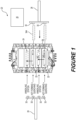
- the first transfer arm 26 includes at least one blank holder 30, such as a hydraulically operated clamp, an energized magnet, a suction device, or any other implements conventionally utilized for moving blanks between locations.
- the at least one blank holder 30 may include a first blank holder and a second blank holder 30.
- the second transfer arm 28 includes at least one shaped part holder 32, such as a hydraulically operated clamp, an energized magnet, a suction device, or any other implements conventionally utilized for moving shaped blanks between locations.
- the at least one shaped part holder 32 may include a first shaped part holder, a second first shaped part holder, a third shaped part holder, and a fourth shaped part holder 32.
- the upper forming die channels 42 and the lower forming die channels 44 thus provide quenching of the shaped part 34B with liquid coolant that is circulated therein or static cooling devices that are located therein.
- the quenching process in the hot forming dies 22 may thus circulate coolant and change the microstructure in at least a portion of the shaped part 34B (e.g., forming martensite).
- the shaped part 34B is cooled at a rate of at least 27°C per second and martensite may be formed between 200°C and 400°C.
- the upper forming die 36 and the lower forming die 38 may define a bend portion 46 of the cavity 40 that forms a stiffener flange 35 in the shaped part 34B.
- Cooling channels 42, 44 may be located adjacent to the entire outline wherein the shaped part 34B will be located, including the bend portion 46 such that primarily the entire shaped part is quenched.
- the coolant in the forming die 22 may include a liquid, such as water, circulated at a temperature between 7°C and 38°C.
- FIGS 3A and 3B are cross-sectional side views of the annealing die 24 located within the hot stamp tool assembly 20.
- Each of the annealing dies 24 may include the same configuration and operational parameters.
- the annealing die 24 includes an upper annealing die 48 and an lower annealing die 50 defining an annealing cavity 52 therebetween. Inner surfaces of the upper annealing die 48 and an lower annealing die may include topographical features similar to that of the hot forming dies 22.
- the upper annealing die 48 includes a series of upper die channels 54 located adjacent to the annealing cavity 52 and the lower annealing die 50 includes a series of lower die channels 56 located adjacent to the annealing cavity 52.
- the upper die channels 54 and the lower die channels 56 may provide continued cooling of the shaped part 34B with coolant that is circulated therein or static cooling materials that are located therein.
- the cooling operation in the annealing die 24 may cause further reduce the temperature of portions of the shaped part 34B to between 0°C and 150°C.
- the coolant in the annealing die 24 may include a liquid, such as water, circulated at a temperature between 20°C and 35°C.
- the shaped part 34B is placed in the annealing die 24 once it reaches a temperature below 200°C.
- the upper annealing die 48 may include at least one upper heating element, such as an upper induction coil 58 located adjacent to the annealing cavity 52 and the lower annealing die 50 may include at least one lower heating element, such as a lower induction coil 60, located adjacent to the annealing cavity 52.
- the at least one lower induction coil 58 may be disposed adjacent to and on an opposite side of the cavity 52 from the at least one upper induction coil 60.
- the upper annealing die 48 includes two upper induction coils 58 located in a spaced relationship, wherein the series of upper die channels 54 are located between each of the upper induction coils 48.
- the lower annealing die 50 may include two lower induction coils 60 located in a spaced relationship, wherein the series of lower die channels 56 are located between each of the lower induction coils 60.
- the die channels 54, 56 are located on either side of the induction coils 58, 60.
- the induction coils 58, 60 are located at a trim location of the shaped part 34B.
- the induction coils 58, 60 may rapidly heat and anneal the shaped part 34B at the trim location while the cooling channels 54, 56 maintain a lower temperature on locations of the shaped part 34B adjacent to the induction coils 58, 60, thus decreasing the creeping effect of the heat transfer and a reducing the size of a transition zone between the annealed portions of the shaped part 34B and the non-annealed portions of the shaped portion 34B.
- the annealing die 24 may include a annealing die insert that includes an upper annealing die insert 62 and a lower annealing die insert 64 that can be moved independently of the upper annealing die 48 and the lower annealing die 50.
- the upper and lower annealing die inserts 62, 64 define an annealing insert cavity 66 with a bend 68 that accommodates the stiffener flange 35. Both annealing inserts 62, 64 are located on an outside portion of annealing die 24 from the induction coils 58, 60.
- the quenched area is spaced from the stiffener flange 35 by a portion of the annealed part 34C which has been softened through annealing.
- the stiffener flange 35 can later be removed via cutting. No cooling channels may be necessary next to the stiffener flange 35 if it will be removed.
- the die channels 54, 56 opposite the stiffener flange 35 hinder the transition zone from creeping into portions other than the annealed portion and the stiffener flange 35.
- the stiffener flange 35 also prevents distortion of the annealed part 34C during the annealing process.
- the die channels 54, 56 may be located on opposite sides of the induction coils 58, 60.
- the stiffener flange 35 may be quenched such that a trimming operation on the annealed portion is modified.
- the trim portion and/or trimming operation may include deforming, piercing, cutting, etc. without departure from the subject disclosure.
- the annealed portion may be completely surrounded by the quenched portions.
- the trim portion is inset from but outlines an entire or partial periphery of the annealed part 34C.
- the upper and lower annealing die inserts 62, 64 may perform the trimming operation.
- the memory 86 may include Random Access Memory (RAM), a Read-Only Memory (ROM), or a combination thereof.
- the memory 86 may include instructions that, when executed by the processor 84, cause the processor 84 to, at least, perform the systems and methods described herein.
- the controller 82 may control operations of the forming die 22, the annealing die 24, the first transfer arm 26, the second transfer arm 28, and other features.
- FIG 5 is a series of top views of the hot stamp tool illustrating sequential steps of a process 100 of forming tailored temper properties in a part with small transition zones. Each step in the process 100 may be carried out by instructions from the memory executed by the processor. Each of the hot stamp tools illustrated in Figure 5 is the same hot stamp tool as a function of time during the course of process 100.
- the process 100 begins with providing 102 a hot stamp tool having a pair of annealing dies and a pair of hot forming dies, wherein the hot forming dies each include a blank and the annealing dies each include a shaped part (which was previously a blank formed in one of the hot forming dies).
- the hot forming dies shape 106 the blanks into a shaped part and may further include a quenching 108 step, such as by a series of cooling channels, wherein a hardened microstructure may be formed within the shaped part.
- the annealing die simultaneously cools 110 and anneals 112 adjacent locations on the shaped part to form an annealed part.
- the step of annealing may include heating with an induction coil and the step of cooling may including cooling channels located adjacent to the induction coil.
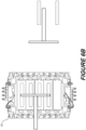
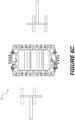
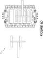
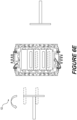
- Figures 6A through 6F show enlarged steps 102 through 120 of the process 100. More particularly, Figure 6A illustrates providing 102 a hot stamp tool having a pair of annealing dies and a pair of hot forming dies, wherein the hot forming dies each include a blank and the annealing dies each include a shaped part (which was previously a blank formed in one of the hot forming dies).
- Figure 6B illustrates the second transfer arm grabbing 114 each of the shaped parts and each of the annealed parts and moving 116 the shaped parts to the annealing dies and moving 118 the annealed parts away from the hot stamp assembly.
- Figure 7 illustrates a series of cross-sectional views of a part undergoing a process 200 of forming tailored temper properties with small transition zones. Each step in the process 200 may be carried out by instructions from the memory executed by the processor. The process 200 presented in Figure 7 may be included with non-overlapping steps in process 100, for example, between steps 102 through 112. More particularly, the process begins by providing 202 a heated blank directly from a furnace. The heated blank is then placed 204 within a hot forming die, wherein it is shaped 206 and quenched 208 via cooling channels to from a shaped part with a hardened microstructure, e.g., higher levels of martensite.
- a hot forming die wherein it is shaped 206 and quenched 208 via cooling channels to from a shaped part with a hardened microstructure, e.g., higher levels of martensite.
- the shaped part is placed 210 within an annealing die, wherein it continues to be cooled 212 via die channels and locally annealed 214 with induction coils that are adjacent to the die channels.
- the step of cooling may include cooling portions of the shaped part adjacent to the induction coils to a temperature between 0°C and 150°C. The portion of the shaped part that is cooled is entirely within the space between adjacent pairs of induction coils presented in Figure 3A and Figure 3B .
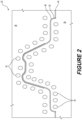
- the local annealing 214 step may include forming an annealed portion within or adjacent to a non-annealed portion, wherein a transition zone at least partially separates the annealed portion from the non-annealed portion and at least part, a majority, or substantially all the transition zone is less that 20mm, less than 15mm, approximately 10mm, or less than 10mm.
- the later processing includes deforming 218 the annealed portion.
- the step of deforming 218 may include one of cutting, riveting, bending, piercing, trimming to size, etc.
- the step of cutting may including laser cutting.
- the resulting part 220 may be a part of an automobile for example a pillar and more specifically a B-pillar.
- Figure 8 illustrates a part 300 having at least one non-annealed portion 302 with a small transition zone 304 that includes at least one deformation 306. More particularly, the part 300 is illustrated as a B-pillar with a transition zone 304 forming an outer edge that includes a deformation 306 including a cut along a peripheral edge of the transition zone 304.
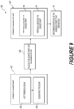
- Figure 9 is a flowchart of a method 400 of forming a part with tailored temper properties and small transition zones.
- the method 400 begins by hot forming 402 and quenching 404 a blank in a hot forming die until it is a shaped part 401.
- the step of quenching 404 may include changing the microstructure of the shaped part.
- the method 400 continues by placing 406 the shaped part in an annealing die wherein it is partially cooled 408 and partially heated 410, simultaneously and at adjacent locations, until it is an annealed part 407 with a small transition zone between the annealed portions and the non-annealed portions.
- a portion of the annealed part that was heated 410 i.e., an annealed portion of the annealed part
Landscapes
- Engineering & Computer Science (AREA)
- Chemical & Material Sciences (AREA)
- Mechanical Engineering (AREA)
- Physics & Mathematics (AREA)
- Thermal Sciences (AREA)
- Crystallography & Structural Chemistry (AREA)
- Materials Engineering (AREA)
- Metallurgy (AREA)
- Organic Chemistry (AREA)
- Heat Treatment Of Articles (AREA)
Claims (15)
- Heißprägewerkzeuganordnung (20) mit:mindestens einer Warmformmatrize (22) und mindestens einer Glühmatrize (24);wobei die mindestens eine Warmformmatrize (22) eine obere Formmatrize (36) und eine untere Formmatrize (38) zum Formen eines Rohlings zu einem Formteil umfasst;wobei die mindestens eine Glühmatritze (24) eine obere Glühmatritze (48) und eine untere Glühmatritze (50) zum Aufnehmen des geformten Teils umfasst;wobei die mindestens eine Glühmatritze (24) mindestens ein Kühlelement (56) und mindestens ein Heizelement (58, 60) umfasst, wobei das Kühlelement benachbart zu dem Heizelement angeordnet ist; undwobei das mindestens eine Heizelement (58, 60) einen Teil des geformten Rohlings glüht und das mindestens eine Kühlelement (56) gleichzeitig einen Teil des geformten Rohlings benachbart zu dem mindestens einen Heizelement (58, 60) kühlt, um eine Wärmeübertragung von dem mindestens einen Heizelement (58, 60) zu dem gekühlten Teil zu verhindern.
- Heißprägewerkzeuganordnung (20) nach Anspruch 1, wobei das mindestens eine Heizelement (58, 60) eine obere Induktionsspule, die in der oberen Glühmatrize (48) angeordnet ist, und eine untere Induktionsspule, die in der unteren Glühmatrize (50) angeordnet ist, umfasst.
- Heißprägewerkzeuganordnung (20) nach Anspruch 2, wobei das mindestens eine Kühlelement (56) obere Matrizenkanäle umfasst, die in der oberen Glühmatrize (48) benachbart zur oberen Induktionsspule angeordnet sind, und einen unteren Matrizenkanal, der in der unteren Glühmatrize (50) benachbart zur Induktionsspule angeordnet ist, wobei die oberen Matrizenkanäle und die unteren Matrizenkanäle ein Kühlmittel benachbart zu den Induktionsspulen übertragen.
- Heißprägewerkzeuganordnung (20) nach Anspruch 1, die ferner einen ersten Transferarm (26) zum Einlegen mindestens eines Rohlings in die mindestens eine Warmformmatrize (22) und einen zweiten Transferarm (28) zum Entnehmen des mindestens einen Rohlings, sobald er zu einem Formteil geformt worden ist, und zum Einlegen des Formteils in die mindestens eine Glühmatrize (24) umfasst.
- Die Heißprägewerkzeuganordnung (20) nach Anspruch 4, wobei die mindestens eine Warmformmatrize (22) eine erste Warmformmatrize und eine zweite Warmformmatrize umfasst und wobei die mindestens eine Glühmatrize (24) eine erste Glühmatrize und eine zweite Glühmatrize umfasst.
- Die Heißprägewerkzeuganordnung (20) nach Anspruch 5, wobei der erste Transferarm (26) einen ersten Rohteilhalter (30) und einen zweiten Rohteilhalter (30) zum gleichzeitigen Einlegen eines ersten Rohteils in die erste Heißform und eines zweiten Rohteils in die zweite Heißform umfasst.
- Die Heißprägewerkzeuganordnung (20) nach Anspruch 6, wobei der zweite Transferarm (28) einen ersten Formteilhalter (32) und einen zweiten Formteilhalter (32) zum Entnehmen des Formteils aus der ersten Warmformmatrize und der zweiten Warmformmatrize und zum Einlegen in die erste Glühmatrize und die zweite Glühmatrize umfasst, und wobei der zweite Transferarm (28) einen dritten Halter (32) und einen vierten Halter (32) zum Entfernen eines Teils aus der ersten Glühmatrize und der zweiten Glühmatrize gleichzeitig mit dem Entfernen des Formteils aus der ersten Warmformmatrize und der zweiten Warmformmatrize umfasst.
- Heißprägewerkzeuganordnung (20) nach Anspruch 7, wobei die erste Warmformmatrize und die zweite Warmformmatrize durch die erste Glühmatrize voneinander beabstandet sind und wobei die erste Glühmatrize und die zweite Glühmatrize durch die zweite Warmformmatrize voneinander beabstandet sind.
- Heißprägewerkzeuganordnung (20) nach Anspruch 1, ferner mit einem Steuersystem, das umfasst:einen Prozessor (84);einen Speicher (86), der Befehle enthält, die, wenn sie vom Prozessor (84) ausgeführt werden, den Prozessor (84) veranlassen:mit dem mindestens einen Heizelement (58, 60) mindestens einen Abschnitt des Formteils über eine Rekristallisationstemperatur zu erwärmen; undmit dem mindestens einen Kühlelement (56) mindestens einen Abschnitt des Formteils, der an den mindestens einen erhitzten Abschnitt angrenzt, zu kühlen.
- Die Heißprägewerkzeuganordnung (20) nach Anspruch 9, wobei der Prozessor (84) ferner veranlasst wird, mit dem mindestens einen Kühlelement (56) den mindestens einen Abschnitt des Formteils, der an den mindestens einen erwärmten Abschnitt angrenzt, auf eine Temperatur zwischen 0°C und 150°C zu kühlen.
- Heißprägewerkzeuganordnung (20) nach Anspruch 9, wobei die mindestens eine Heißformmatrize (22) obere Kühlkanäle in der oberen Formmatrize (36) und untere Kühlkanäle in der unteren Formmatrize (38) umfasst.
- Heißprägewerkzeuganordnung (20) nach Anspruch 11, wobei der Prozessor (84) ferner veranlasst wird, mit den oberen Kühlkanälen und den unteren Kühlkanälen das Formteil zu kühlen, um die Wärmeübertragung von dem mindestens einen Heizelement (58, 60) zu umgebenden Abschnitten des Formteils zu verlangsamen.
- Verfahren zum Formen eines Teils mit maßgeschneiderten Temperierungseigenschaften und kleinen Übergangszonen, das die folgenden Schritte umfasst:Warmformen eines Rohlings in einer Warmformmatrize (22), bis er ein Formteil ist;Einlegen des Formteils in eine Glühmatrize (24) und gleichzeitiges teilweises Abkühlen und teilweises Erwärmen des Formteils an benachbarten Stellen, um mindestens einen geglühten Abschnitt und mindestens einen nicht geglühten Abschnitt mit einer kleinen Übergangszone dazwischen zu bilden; undVerformen des geglühten Abschnitts.
- Verfahren nach Anspruch 13, wobei die kleine Übergangszone weniger als 20 mm beträgt.
- Verfahren nach Anspruch 13, das ferner das teilweise Abkühlen auf eine Temperatur zwischen 0°C und 150°C und das teilweise Erwärmen auf eine Temperatur bei oder über einer Rekristallisationstemperatur umfasst.
Applications Claiming Priority (2)
| Application Number | Priority Date | Filing Date | Title |
|---|---|---|---|
| US201962940809P | 2019-11-26 | 2019-11-26 | |
| PCT/CA2020/051615 WO2021102573A1 (en) | 2019-11-26 | 2020-11-26 | Hot stamp tooling assembly and method of forming a part with tailored temper properties |
Publications (3)
| Publication Number | Publication Date |
|---|---|
| EP4065296A1 EP4065296A1 (de) | 2022-10-05 |
| EP4065296A4 EP4065296A4 (de) | 2023-12-13 |
| EP4065296B1 true EP4065296B1 (de) | 2025-07-02 |
Family
ID=76128565
Family Applications (1)
| Application Number | Title | Priority Date | Filing Date |
|---|---|---|---|
| EP20891842.5A Active EP4065296B1 (de) | 2019-11-26 | 2020-11-26 | Heissprägewerkzeuganordnung und verfahren zur herstellung eines teils mit massgeschneiderten härteeigenschaften |
Country Status (7)
| Country | Link |
|---|---|
| US (1) | US20220410239A1 (de) |
| EP (1) | EP4065296B1 (de) |
| CN (1) | CN114728324A (de) |
| CA (1) | CA3157083A1 (de) |
| ES (1) | ES3037689T3 (de) |
| MX (1) | MX2022005769A (de) |
| WO (1) | WO2021102573A1 (de) |
Families Citing this family (3)
| Publication number | Priority date | Publication date | Assignee | Title |
|---|---|---|---|---|
| WO2021009614A1 (en) * | 2019-07-12 | 2021-01-21 | Magna International Inc. | Machining of steel at elevated surface temperatures |
| US12138678B2 (en) * | 2022-10-24 | 2024-11-12 | Martinrea International US Inc. | Tailor hardening of such as a cold stamped vehicle door pillar using advanced high strength steel to exhibit each of hard, transition and soft zones |
| CN116313656B (zh) * | 2023-04-04 | 2024-01-30 | 东莞市富瑞电子科技有限公司 | 保险丝加工方法 |
Family Cites Families (24)
| Publication number | Priority date | Publication date | Assignee | Title |
|---|---|---|---|---|
| KR100375347B1 (ko) | 2000-01-13 | 2003-03-10 | 반봉찬 | 폐 코크스냉각분진을 이용한 여과재대체제 및 그의 제조방법 |
| KR101164323B1 (ko) * | 2009-12-28 | 2012-07-09 | 현대하이스코 주식회사 | 국부적으로 이종 강도를 갖는 열간 프레스 성형체 제조용 금형 시스템 및 이를 이용한 성형체 제조방법 |
| DE102010004081C5 (de) * | 2010-01-06 | 2016-11-03 | Benteler Automobiltechnik Gmbh | Verfahren zum Warmformen und Härten einer Platine |
| JP5508059B2 (ja) * | 2010-02-26 | 2014-05-28 | アイシン高丘株式会社 | 複合型プレス加工装置 |
| CN103108964B (zh) * | 2010-08-31 | 2015-06-17 | 塔塔钢铁艾默伊登有限责任公司 | 热成形涂覆的金属部件的方法和成形的部件 |
| DE102011011013B4 (de) * | 2011-02-11 | 2017-07-13 | Schuler Pressen Gmbh | Pressenanlage zum Umformen oder Bearbeiten von meta llischen Bauteilen |
| US8561450B2 (en) * | 2011-03-11 | 2013-10-22 | GM Global Technology Operations LLC | System and method for annealing of a pre-formed panel |
| KR101450386B1 (ko) * | 2012-04-13 | 2014-10-14 | 현대하이스코 주식회사 | 스크랩 처리 장치가 필요치 않은 핫스탬핑 성형장치 및 이를 이용한 핫스탬핑 성형방법 |
| WO2015077185A1 (en) * | 2013-11-25 | 2015-05-28 | Magna International Inc. | Structural component including a tempered transition zone |
| DE102013225409A1 (de) * | 2013-12-10 | 2015-06-11 | Muhr Und Bender Kg | Verfahren und Vorrichtung zur Nachbehandlung eines gehärteten metallischen Formteils mittels elektrischer Widerstandserwärmung |
| EP3124637B9 (de) * | 2014-03-26 | 2019-12-04 | Nippon Steel Corporation | Hochfestes, warmgeformtes stahlblechelement |
| DE102014112244A1 (de) | 2014-08-26 | 2016-03-03 | Benteler Automobiltechnik Gmbh | Verfahren und Presse zur Herstellung wenigstens abschnittsweise gehärteter Blechbauteile |
| KR101523177B1 (ko) * | 2014-12-11 | 2015-05-27 | 현대하이스코 주식회사 | 금형의 도금소착 방지를 위한 핫스탬핑 장치 및 방법 |
| DE102014119545A1 (de) | 2014-12-23 | 2016-06-23 | Benteler Automobiltechnik Gmbh | Federnd gelagertes segmentiertes Warmumformwerkzeug und Verfahren zur Herstellung eines warmumform- und pressgehärteten Stahlbauteils mit scharf berandetem Übergangsbereich |
| EP3067129A1 (de) * | 2015-03-09 | 2016-09-14 | Autotech Engineering, A.I.E. | Presssysteme und -verfahren |
| EP3072980B1 (de) * | 2015-03-26 | 2018-02-14 | weba Werkzeugbau Betriebs GmbH | Verfahren und vorrichtung zur herstellung eines partiell gehärteten formteils |
| US9968977B2 (en) * | 2015-07-06 | 2018-05-15 | GM Global Technology Operations LLC | Method of shaping a component |
| DE102015122796A1 (de) * | 2015-12-23 | 2017-06-29 | Benteler Automobiltechnik Gmbh | Warmformlinie zur Herstellung warmumgeformter und pressgehärteter Stahlblechprodukte sowie Verfahren zu dessen Betreibung |
| DE112017002311T5 (de) * | 2016-05-04 | 2019-02-14 | Magna International Inc. | Warmform-Werkzeug mit Infrarot-Lichtquelle |
| RU2019104106A (ru) | 2016-08-09 | 2020-09-15 | Аутотек Инжиниринг, C.Л. | Центрирование и выборочное нагревание заготовок |
| US10697035B2 (en) | 2017-10-03 | 2020-06-30 | Ford Motor Company | 3-D printed cooling channels to produce PHS parts with tailored properties |
| DE102018206343A1 (de) * | 2018-04-25 | 2019-10-31 | Volkswagen Aktiengesellschaft | Verfahren und Anlage zur Serienfertigung warmumgeformter Blechformteile aus einem Stahlblechband |
| ES3029756T3 (en) * | 2018-10-10 | 2025-06-25 | Unipres Corp | Method for manufacturing a press-molded article, a retainer, and a manufacturing system for a press-molded article |
| US12121950B2 (en) * | 2019-05-06 | 2024-10-22 | Magna International, Inc. | Conductive post-furnace heating of sheet for hot forming |
-
2020
- 2020-11-26 US US17/779,284 patent/US20220410239A1/en active Pending
- 2020-11-26 WO PCT/CA2020/051615 patent/WO2021102573A1/en not_active Ceased
- 2020-11-26 MX MX2022005769A patent/MX2022005769A/es unknown
- 2020-11-26 EP EP20891842.5A patent/EP4065296B1/de active Active
- 2020-11-26 CN CN202080081477.0A patent/CN114728324A/zh active Pending
- 2020-11-26 CA CA3157083A patent/CA3157083A1/en active Pending
- 2020-11-26 ES ES20891842T patent/ES3037689T3/es active Active
Also Published As
| Publication number | Publication date |
|---|---|
| CN114728324A (zh) | 2022-07-08 |
| MX2022005769A (es) | 2022-06-09 |
| EP4065296A4 (de) | 2023-12-13 |
| US20220410239A1 (en) | 2022-12-29 |
| EP4065296A1 (de) | 2022-10-05 |
| CA3157083A1 (en) | 2021-06-03 |
| WO2021102573A1 (en) | 2021-06-03 |
| ES3037689T3 (en) | 2025-10-06 |
Similar Documents
| Publication | Publication Date | Title |
|---|---|---|
| US9359663B2 (en) | Manufacturing method for hot press formed steel member | |
| CN108453175B (zh) | 热冲压成型方法 | |
| EP4065296B1 (de) | Heissprägewerkzeuganordnung und verfahren zur herstellung eines teils mit massgeschneiderten härteeigenschaften | |
| EP2585621B1 (de) | Massgeschneiderte eigenschaften durch nachbearbeitung nach einer heissformung | |
| CN113249556B (zh) | 具有至少两个强度不同的区域的汽车组件的制备方法 | |
| US9279167B2 (en) | Method of forming a stamped article | |
| ES2955824T3 (es) | Método para recortar una pieza conformada en caliente | |
| US20160059295A1 (en) | Method and press for producing sheet metal parts that are hardened at least in regions | |
| EP2953742B1 (de) | Heissformungsanordnung und verfahren zur herstellung eines wärmebehandelten teils | |
| WO2009123804A1 (en) | Microstructural optimization of automotive structures | |
| KR101494113B1 (ko) | 프레스 성형품 및 그 제조 방법 | |
| WO2017190220A1 (en) | Hot forming tool with infrared light source | |
| US8778101B2 (en) | Method of production of steel sheet pressed parts with locally modified properties | |
| WO2016106621A1 (en) | Method of hot forming a component from steel | |
| RU2743046C1 (ru) | Способ производства компонента в результате дополнительной формовки предварительно сформованного контура | |
| CN108380745A (zh) | 制造压制淬火部件的方法以及压模 | |
| US12012641B2 (en) | Combined heating and transfer of work-piece blanks | |
| EP4556578A1 (de) | Verfahren und vorrichtung zur lokalen weichmachung eines heissgeprägten elements | |
| JP2026503993A (ja) | ホットスタンピング部品の製造方法 | |
| CN113423518B (zh) | 用于在热冲压工具中使用空气间隙来形成定制回火特性的方法和系统 | |
| CN118369169A (zh) | 热冲压系统及方法 | |
| CN119487222A (zh) | 用于制造用于机动车的加压硬化的门环和至少一个另外的加压硬化的构件的方法 | |
| MX2007001270A (en) | Method for press quenching components consisting of sheet steel |
Legal Events
| Date | Code | Title | Description |
|---|---|---|---|
| STAA | Information on the status of an ep patent application or granted ep patent |
Free format text: STATUS: THE INTERNATIONAL PUBLICATION HAS BEEN MADE |
|
| PUAI | Public reference made under article 153(3) epc to a published international application that has entered the european phase |
Free format text: ORIGINAL CODE: 0009012 |
|
| STAA | Information on the status of an ep patent application or granted ep patent |
Free format text: STATUS: REQUEST FOR EXAMINATION WAS MADE |
|
| 17P | Request for examination filed |
Effective date: 20220525 |
|
| AK | Designated contracting states |
Kind code of ref document: A1 Designated state(s): AL AT BE BG CH CY CZ DE DK EE ES FI FR GB GR HR HU IE IS IT LI LT LU LV MC MK MT NL NO PL PT RO RS SE SI SK SM TR |
|
| DAV | Request for validation of the european patent (deleted) | ||
| DAX | Request for extension of the european patent (deleted) | ||
| A4 | Supplementary search report drawn up and despatched |
Effective date: 20231109 |
|
| RIC1 | Information provided on ipc code assigned before grant |
Ipc: B21D 22/02 20060101ALI20231103BHEP Ipc: C21D 8/00 20060101ALI20231103BHEP Ipc: C21D 1/26 20060101ALI20231103BHEP Ipc: B21D 37/08 20060101ALI20231103BHEP Ipc: B21D 37/16 20060101AFI20231103BHEP |
|
| REG | Reference to a national code |
Ref country code: DE Ref legal event code: R079 Free format text: PREVIOUS MAIN CLASS: B21D0037160000 Ipc: B21D0022200000 Ref country code: DE Ref legal event code: R079 Ref document number: 602020054002 Country of ref document: DE Free format text: PREVIOUS MAIN CLASS: B21D0037160000 Ipc: B21D0022200000 |
|
| RIC1 | Information provided on ipc code assigned before grant |
Ipc: C21D 11/00 20060101ALN20241001BHEP Ipc: C21D 1/42 20060101ALN20241001BHEP Ipc: B21D 22/02 20060101ALN20241001BHEP Ipc: B21D 35/00 20060101ALN20241001BHEP Ipc: C21D 9/00 20060101ALI20241001BHEP Ipc: C21D 8/00 20060101ALI20241001BHEP Ipc: C21D 1/673 20060101ALI20241001BHEP Ipc: B21D 37/08 20060101ALI20241001BHEP Ipc: C21D 1/26 20060101ALI20241001BHEP Ipc: B21D 37/16 20060101ALI20241001BHEP Ipc: B21D 22/20 20060101AFI20241001BHEP |
|
| RIC1 | Information provided on ipc code assigned before grant |
Ipc: C21D 11/00 20060101ALN20241126BHEP Ipc: C21D 1/42 20060101ALN20241126BHEP Ipc: B21D 22/02 20060101ALN20241126BHEP Ipc: B21D 35/00 20060101ALN20241126BHEP Ipc: C21D 9/00 20060101ALI20241126BHEP Ipc: C21D 8/00 20060101ALI20241126BHEP Ipc: C21D 1/673 20060101ALI20241126BHEP Ipc: B21D 37/08 20060101ALI20241126BHEP Ipc: C21D 1/26 20060101ALI20241126BHEP Ipc: B21D 37/16 20060101ALI20241126BHEP Ipc: B21D 22/20 20060101AFI20241126BHEP |
|
| GRAP | Despatch of communication of intention to grant a patent |
Free format text: ORIGINAL CODE: EPIDOSNIGR1 |
|
| STAA | Information on the status of an ep patent application or granted ep patent |
Free format text: STATUS: GRANT OF PATENT IS INTENDED |
|
| INTG | Intention to grant announced |
Effective date: 20250130 |
|
| GRAS | Grant fee paid |
Free format text: ORIGINAL CODE: EPIDOSNIGR3 |
|
| GRAA | (expected) grant |
Free format text: ORIGINAL CODE: 0009210 |
|
| STAA | Information on the status of an ep patent application or granted ep patent |
Free format text: STATUS: THE PATENT HAS BEEN GRANTED |
|
| P01 | Opt-out of the competence of the unified patent court (upc) registered |
Free format text: CASE NUMBER: APP_22427/2025 Effective date: 20250513 |
|
| AK | Designated contracting states |
Kind code of ref document: B1 Designated state(s): AL AT BE BG CH CY CZ DE DK EE ES FI FR GB GR HR HU IE IS IT LI LT LU LV MC MK MT NL NO PL PT RO RS SE SI SK SM TR |
|
| REG | Reference to a national code |
Ref country code: GB Ref legal event code: FG4D |
|
| REG | Reference to a national code |
Ref country code: CH Ref legal event code: EP |
|
| REG | Reference to a national code |
Ref country code: DE Ref legal event code: R096 Ref document number: 602020054002 Country of ref document: DE |
|
| REG | Reference to a national code |
Ref country code: IE Ref legal event code: FG4D |
|
| REG | Reference to a national code |
Ref country code: ES Ref legal event code: FG2A Ref document number: 3037689 Country of ref document: ES Kind code of ref document: T3 Effective date: 20251006 |
|
| REG | Reference to a national code |
Ref country code: NL Ref legal event code: MP Effective date: 20250702 |
|
| PG25 | Lapsed in a contracting state [announced via postgrant information from national office to epo] |
Ref country code: PT Free format text: LAPSE BECAUSE OF FAILURE TO SUBMIT A TRANSLATION OF THE DESCRIPTION OR TO PAY THE FEE WITHIN THE PRESCRIBED TIME-LIMIT Effective date: 20251103 |
|
| PG25 | Lapsed in a contracting state [announced via postgrant information from national office to epo] |
Ref country code: NL Free format text: LAPSE BECAUSE OF FAILURE TO SUBMIT A TRANSLATION OF THE DESCRIPTION OR TO PAY THE FEE WITHIN THE PRESCRIBED TIME-LIMIT Effective date: 20250702 |
|
| REG | Reference to a national code |
Ref country code: AT Ref legal event code: MK05 Ref document number: 1808694 Country of ref document: AT Kind code of ref document: T Effective date: 20250702 |
|
| PG25 | Lapsed in a contracting state [announced via postgrant information from national office to epo] |
Ref country code: IS Free format text: LAPSE BECAUSE OF FAILURE TO SUBMIT A TRANSLATION OF THE DESCRIPTION OR TO PAY THE FEE WITHIN THE PRESCRIBED TIME-LIMIT Effective date: 20251102 |
|
| PGFP | Annual fee paid to national office [announced via postgrant information from national office to epo] |
Ref country code: DE Payment date: 20250930 Year of fee payment: 6 |
|
| PG25 | Lapsed in a contracting state [announced via postgrant information from national office to epo] |
Ref country code: NO Free format text: LAPSE BECAUSE OF FAILURE TO SUBMIT A TRANSLATION OF THE DESCRIPTION OR TO PAY THE FEE WITHIN THE PRESCRIBED TIME-LIMIT Effective date: 20251002 |
|
| REG | Reference to a national code |
Ref country code: LT Ref legal event code: MG9D |
|
| PG25 | Lapsed in a contracting state [announced via postgrant information from national office to epo] |
Ref country code: AT Free format text: LAPSE BECAUSE OF FAILURE TO SUBMIT A TRANSLATION OF THE DESCRIPTION OR TO PAY THE FEE WITHIN THE PRESCRIBED TIME-LIMIT Effective date: 20250702 |
|
| PG25 | Lapsed in a contracting state [announced via postgrant information from national office to epo] |
Ref country code: FI Free format text: LAPSE BECAUSE OF FAILURE TO SUBMIT A TRANSLATION OF THE DESCRIPTION OR TO PAY THE FEE WITHIN THE PRESCRIBED TIME-LIMIT Effective date: 20250702 |
|
| PG25 | Lapsed in a contracting state [announced via postgrant information from national office to epo] |
Ref country code: HR Free format text: LAPSE BECAUSE OF FAILURE TO SUBMIT A TRANSLATION OF THE DESCRIPTION OR TO PAY THE FEE WITHIN THE PRESCRIBED TIME-LIMIT Effective date: 20250702 |
|
| PG25 | Lapsed in a contracting state [announced via postgrant information from national office to epo] |
Ref country code: GR Free format text: LAPSE BECAUSE OF FAILURE TO SUBMIT A TRANSLATION OF THE DESCRIPTION OR TO PAY THE FEE WITHIN THE PRESCRIBED TIME-LIMIT Effective date: 20251003 |
|
| PG25 | Lapsed in a contracting state [announced via postgrant information from national office to epo] |
Ref country code: SE Free format text: LAPSE BECAUSE OF FAILURE TO SUBMIT A TRANSLATION OF THE DESCRIPTION OR TO PAY THE FEE WITHIN THE PRESCRIBED TIME-LIMIT Effective date: 20250702 |
|
| PG25 | Lapsed in a contracting state [announced via postgrant information from national office to epo] |
Ref country code: LV Free format text: LAPSE BECAUSE OF FAILURE TO SUBMIT A TRANSLATION OF THE DESCRIPTION OR TO PAY THE FEE WITHIN THE PRESCRIBED TIME-LIMIT Effective date: 20250702 |
|
| PG25 | Lapsed in a contracting state [announced via postgrant information from national office to epo] |
Ref country code: PL Free format text: LAPSE BECAUSE OF FAILURE TO SUBMIT A TRANSLATION OF THE DESCRIPTION OR TO PAY THE FEE WITHIN THE PRESCRIBED TIME-LIMIT Effective date: 20250702 Ref country code: BG Free format text: LAPSE BECAUSE OF FAILURE TO SUBMIT A TRANSLATION OF THE DESCRIPTION OR TO PAY THE FEE WITHIN THE PRESCRIBED TIME-LIMIT Effective date: 20250702 |
|
| PG25 | Lapsed in a contracting state [announced via postgrant information from national office to epo] |
Ref country code: RS Free format text: LAPSE BECAUSE OF FAILURE TO SUBMIT A TRANSLATION OF THE DESCRIPTION OR TO PAY THE FEE WITHIN THE PRESCRIBED TIME-LIMIT Effective date: 20251002 |
|
| PGFP | Annual fee paid to national office [announced via postgrant information from national office to epo] |
Ref country code: ES Payment date: 20251211 Year of fee payment: 6 |
|
| PG25 | Lapsed in a contracting state [announced via postgrant information from national office to epo] |
Ref country code: RO Free format text: LAPSE BECAUSE OF FAILURE TO SUBMIT A TRANSLATION OF THE DESCRIPTION OR TO PAY THE FEE WITHIN THE PRESCRIBED TIME-LIMIT Effective date: 20250702 |
|
| PG25 | Lapsed in a contracting state [announced via postgrant information from national office to epo] |
Ref country code: SM Free format text: LAPSE BECAUSE OF FAILURE TO SUBMIT A TRANSLATION OF THE DESCRIPTION OR TO PAY THE FEE WITHIN THE PRESCRIBED TIME-LIMIT Effective date: 20250702 |
|
| PG25 | Lapsed in a contracting state [announced via postgrant information from national office to epo] |
Ref country code: DK Free format text: LAPSE BECAUSE OF FAILURE TO SUBMIT A TRANSLATION OF THE DESCRIPTION OR TO PAY THE FEE WITHIN THE PRESCRIBED TIME-LIMIT Effective date: 20250702 |
|
| PG25 | Lapsed in a contracting state [announced via postgrant information from national office to epo] |
Ref country code: IT Free format text: LAPSE BECAUSE OF FAILURE TO SUBMIT A TRANSLATION OF THE DESCRIPTION OR TO PAY THE FEE WITHIN THE PRESCRIBED TIME-LIMIT Effective date: 20250702 |
|
| PG25 | Lapsed in a contracting state [announced via postgrant information from national office to epo] |
Ref country code: EE Free format text: LAPSE BECAUSE OF FAILURE TO SUBMIT A TRANSLATION OF THE DESCRIPTION OR TO PAY THE FEE WITHIN THE PRESCRIBED TIME-LIMIT Effective date: 20250702 Ref country code: SK Free format text: LAPSE BECAUSE OF FAILURE TO SUBMIT A TRANSLATION OF THE DESCRIPTION OR TO PAY THE FEE WITHIN THE PRESCRIBED TIME-LIMIT Effective date: 20250702 |