EP4065282B1 - Verschleissschutzelement für eine zerkleinerungseinrichtung - Google Patents
Verschleissschutzelement für eine zerkleinerungseinrichtung Download PDFInfo
- Publication number
- EP4065282B1 EP4065282B1 EP20810984.3A EP20810984A EP4065282B1 EP 4065282 B1 EP4065282 B1 EP 4065282B1 EP 20810984 A EP20810984 A EP 20810984A EP 4065282 B1 EP4065282 B1 EP 4065282B1
- Authority
- EP
- European Patent Office
- Prior art keywords
- wear
- resistant element
- ceramic
- protection element
- wear protection
- Prior art date
- Legal status (The legal status is an assumption and is not a legal conclusion. Google has not performed a legal analysis and makes no representation as to the accuracy of the status listed.)
- Active
Links
Images
Classifications
-
- B—PERFORMING OPERATIONS; TRANSPORTING
- B02—CRUSHING, PULVERISING, OR DISINTEGRATING; PREPARATORY TREATMENT OF GRAIN FOR MILLING
- B02C—CRUSHING, PULVERISING, OR DISINTEGRATING IN GENERAL; MILLING GRAIN
- B02C4/00—Crushing or disintegrating by roller mills
- B02C4/28—Details
- B02C4/30—Shape or construction of rollers
- B02C4/305—Wear resistant rollers
-
- B—PERFORMING OPERATIONS; TRANSPORTING
- B02—CRUSHING, PULVERISING, OR DISINTEGRATING; PREPARATORY TREATMENT OF GRAIN FOR MILLING
- B02C—CRUSHING, PULVERISING, OR DISINTEGRATING IN GENERAL; MILLING GRAIN
- B02C15/00—Disintegrating by milling members in the form of rollers or balls co-operating with rings or discs
- B02C15/004—Shape or construction of rollers or balls
- B02C15/005—Rollers or balls of composite construction
-
- B—PERFORMING OPERATIONS; TRANSPORTING
- B02—CRUSHING, PULVERISING, OR DISINTEGRATING; PREPARATORY TREATMENT OF GRAIN FOR MILLING
- B02C—CRUSHING, PULVERISING, OR DISINTEGRATING IN GENERAL; MILLING GRAIN
- B02C2210/00—Codes relating to different types of disintegrating devices
- B02C2210/02—Features for generally used wear parts on beaters, knives, rollers, anvils, linings and the like
Definitions
- the invention relates to a wear protection element for partial insertion into a recess on the surface of a wear surface of a shredding device and to a shredding device with such a wear protection element.
- comminution devices such as grinding rollers, which are used in particular for material bed comminution of, for example, hard ore
- high wear occurs on the surface of a wear surface, such as the grinding roller surface, during operation of the comminution device.
- it is made, for example, from the DE 2006 010 042 A1 known to apply additional wear protection elements to the surface of the grinding roller.
- it is necessary to replace or renew the wear protection elements of the grinding roller, for example, in order to guarantee efficient grinding.
- replacing a worn wear protection element is problematic.
- the connection between the base body and the wear protection element is destroyed by heating and is expelled or pulled out of the recess in the base body, for example a roller body, by means of the gases produced during heating.
- the gases escape through cracks in the material.
- Mechanical removal of the ceramic wear protection element is also complex since, for example, soldering a metal to pull out the wear protection element is not possible. The replacement of the wear protection elements therefore often requires long downtimes of the roller mill as well as high maintenance costs.
- a hard body is known as grid armor for a roller press, a method for its production and a roller for a roller press.
- the invention comprises a wear protection element for partial insertion into a recess on the surface of a wear surface of a comminution device, the wear protection element having a fastening region which can be connected to the recess in the surface of the wear surface and a wear region which is at least partially made up of the Surface of the wear surface protrudes.
- the fastening area is made of a metal.
- the wear area has a jacket and a core arranged at least partially within the jacket, the core being made of a metal and the jacket being made of a ceramic. In particular, the core is arranged completely within the jacket.
- the material of the jacket comprises a ceramic which has yttrium-stabilized, tetragonal polycrystalline zirconium oxide (TPZ), the TPZ having a volume fraction of at least 60%, preferably at least 80%, in particular 95% to 100% of the ceramic.
- TPZ yttrium-stabilized, tetragonal polycrystalline zirconium oxide
- the comminution device is, for example, a roller mill, a roller crusher, a hammer mill or a vertical roller mill, the wear surface being in particular the surface of a grinding roller which is exposed to high levels of wear during operation of the comminution device, the hammer tools and the surface of the grinding track of a hammer mill or the surface of the Rollers and the grinding plate of a vertical roller mill.
- the wear protection element is, for example, cylindrical or has a polygonal cross section.
- one end of the wear protection element is designed such that it is on the surface of the Wear surface, in particular in a recess in the surface of the wear surface, can be fastened.
- the fastening area is preferably arranged in such a way that it is exposed to no or only very little wear during operation of the shredding device.
- the fastening area serves to fasten the wear protection element to the surface of the wear surface.
- the wear area is arranged on the fastening area and preferably extends beyond the fastening area at the height of the wear protection element, so that the wear area is exposed to the majority of the wear acting on the wear protection element.
- the wear area is preferably attached completely outside the surface of the wear area, with only the fastening area being arranged in the recess of the wear area.
- the fastening area and the core of the wear area are, for example, made entirely of a metal, such as steel or hard metal, such as tungsten carbide.
- the jacket is preferably made entirely of ceramic.
- the core is, for example, cylindrical and extends in particular from the fastening area through the entire wear area. It is also conceivable that the core has a square or polygonal cross section. Preferably, the core extends in the axial direction along the central axis of the wear protection element through the wear area. It is also conceivable that the core extends in the axial direction along an outer surface of the wear element.
- Such a wear protection element can be produced much more cost-effectively, since there is no need to form the entire wear protection element from the more expensive, wear-resistant material, such as ceramic.
- the area of the wear protection element which is exposed to no or only very little wear, has a less wear-resistant material, which requires lower material costs.
- a metal core in the wear area offers the advantage that the worn wear protection element can be removed from the recess in the surface of the grinding roller. To remove the wear protection element This is heated, for example, in order to loosen a connection between the fastening area and the wear surface of the shredding device. The wear protection element is then pulled out on the metal core. In the event of severe wear, it is also conceivable to attach a metallic material to the metal core, for example by soldering, and to pull the wear protection element out of the recess in the wear surface.
- the core extends through the entire wear area. This makes it possible to remove the wear protection element in a simple manner, regardless of the extent of the wear.
- the core is firmly connected to the fastening area or is formed in one piece with it.
- the fastening area with the core is produced by casting or machining, such as turning or milling. This ensures removal of the attachment area along with the wear area.
- the core is, for example, cohesively connected to the fastening area, in particular soldered, glued or welded to it.
- the jacket is sleeve-shaped.
- Sleeve-shaped means in particular that the jacket is cylindrical with a central recess, with the core being arranged within the recess.
- the fastening area is preferably cylindrical and the wear area lies against it.
- the material of the jacket comprises a ceramic material, such as tungsten carbide WC, titanium carbide TiC, titanium carbonitride TiCN, vanadium carbide VC, chromium carbide CrC, tantalum carbide TaC, boron carbide BC, niobium carbide NbC, molybdenum carbide Mo2C, aluminum oxide AI2O3, zirconium oxide ZrO2, and/or silicon carbide SiC or a combination of the materials mentioned.
- particles made of industrial diamonds, in particular high-strength ceramics are preferably embedded in a ceramic or metallic matrix in the wear area.
- the material of the jacket comprises a ceramic which has yttrium-stabilized, tetragonal polycrystalline zirconium oxide (TPZ), the TPZ having a volume fraction of at least 60%, preferably at least 80%, in particular 95% to 100% of the ceramic. This has the advantage of increased corrosion resistance of the material, especially during wet grinding.
- TPZ yttrium-stabilized, tetragonal polycrystalline zirconium oxide
- the ceramic has a porosity of less than 5%, preferably less than 4%, in particular less than 3%.
- the ceramic preferably has a porosity of at least 1%.
- a porosity of less than 5%, preferably less than 4%, in particular less than 3% leads to improved wear behavior.
- the aforementioned porosity information is preferably the total porosity, which corresponds to an average value of the pore sizes of the material.
- the pores are substantially evenly distributed throughout the ceramic material.
- the ceramic has a density of 1.5 to 5 g/cm 3 , preferably 2 to 4 g/cm 3 , in particular 2.7 to 3 g/cm 3 .
- the ceramic has an Al2O3 (corundum) content of 10%. This leads to improved wear resistance with a small reduction in the toughness of the ceramic.
- the ceramic in particular has a ratio of monoclinic to tetragonal zirconium oxide of less than 40%, in particular less than 30%, preferably less than 20%.
- the ratio of monoclinic to tetragonal zirconium oxide is preferably at least 2%.
- the zirconium oxide contained in the ceramic has less than 40%, in particular less than 30%, preferably less than 20% monoclinic zirconium oxide, the remaining zirconium oxide being tetragonal zirconium oxide.
- the ratio of monoclinic to tetragonal zirconium oxide is determined, for example, using X-ray diffraction in accordance with ISO 13356.
- the yttrium-stabilized zirconium oxide of the ceramic in particular has a grain size D50 of less than 1.5 ⁇ m, preferably less than 1 ⁇ m, in particular less than 0.8 ⁇ m.
- the D50 grain size of the ceramic is preferably at least 0.2 ⁇ m.
- the D50 value refers to the grain size of 50% of the ceramic grains.
- 50% of the grains of the yttrium-stabilized zirconium oxide have a grain size diameter of less than 1.5 ⁇ m, preferably less than 1 ⁇ m, in particular less than 0.8 ⁇ m.
- the D90 value of the grain size is preferably less than 3 ⁇ m, in particular less than 2 ⁇ m, preferably less than 1.5 ⁇ m. Wear protection elements of a shredding device are exposed to local stresses. Therefore, a wide grain size distribution should be avoided in order to prevent the formation of cracks or breakouts.
- the ceramic has an yttrium content of 2 to 4 mol% Y2O3.
- the advantages of such an yttrium content are better sintering behavior at an even lower sintering temperature, as well as a finer crystalline structure, which in turn leads to higher fatigue resistance and improved fracture toughness.
- the ceramic has, for example, Ce-TZP with a content of 10 to 12 mol% of CeO2.
- the ceramic has a content of 8 to 10 mol% of Mg-PSZ. It is also conceivable that the ceramic has a content of 5 to 10 mol% of MgO as a stabilizer.
- the ceramic has a number of pores with a size of more than 200 ⁇ m of less than 0.1 per mm 2 .
- the number of pores per surface also provides an indication of wear resistance.
- a small number of pores of a relatively large size, such as more than 200 ⁇ m, ensures high wear resistance as local breakouts from the ceramic material are avoided.
- the ceramic preferably has a number of pores with a size of more than 150 ⁇ m of less than 0.4 per mm 2 .
- the ceramic has one The number of pores with a size of more than 100 ⁇ m is less than 2 per mm 2 . Such a number of pores significantly increases the service life of the wear protection element.
- the material of the fastening area comprises a steel, such as a tempered structural steel.
- the jacket is firmly connected to the fastening area, for example materially, such as gluing or soldering, or positively.
- the fastening area comprises less than 50%, preferably less than 20%, most preferably less than 15% of the wear protection element.
- the fastening area comprises at least 10% of the wear protection element.
- the invention further comprises a comminution device having a wear surface and a wear protection element as described above, wherein the wear protection element is at least partially mounted in a recess in the surface of the wear surface, in particular a grinding roller.
- the fastening area of the wear protection element is cohesively connected to the grinding roller, in particular welded, glued or soldered.
- the fastening area is soldered, glued or welded to the recess in the wear surface.
- the shredding device is, for example, a grinding roller for shredding the material bed or a vertical roller mill.
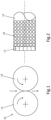
- a comminution device 10 in particular a roller mill, is shown schematically.
- the comminution device 10 comprises two grinding rollers, shown schematically as circles, with wear surfaces 12, 14, which have the same diameter and are arranged next to one another.
- a grinding gap is formed between the wear surfaces 12, 14 of the grinding rollers, the size of which can be adjusted, for example.
- the grinding rollers rotate in opposite directions to one another in the direction of rotation shown by the arrows, with material to be ground passing through the grinding gap in the direction of fall and being ground.
- Fig.2 shows an end region of a grinding roller which has a wear surface 12 on which wear protection elements 16 are attached.
- the wear protection elements 16 are mounted in the outer periphery of the surface of the grinding roller.
- the wear protection elements 16 which are spaced apart from one another and arranged next to one another Fig. 2 a circular cross section. It is also conceivable that the wear protection elements 16 over the surface of the grinding roller in size, number, cross-sectional shape and arrangement vary from one another in order, for example, to compensate for local differences in wear during operation of the shredding device 10.
- the grinding roller has wear protection corner elements 17 attached to its end, which, for example, have a rectangular cross section and are arranged next to one another in a row in such a way that they form a ring over the circumference of the grinding roller.
- Other cross-sectional shapes of the wear protection corner elements 17 are also conceivable, which differ from those in Fig. 2 Cross-sectional shape shown may vary.
- An arrangement of the wear protection corner elements 17 at a distance from one another is also possible.
- Fig. 2 For example, only the left end of the grinding roller with the wear surface 12 is shown, the right end, not shown, advantageously being identical in structure.
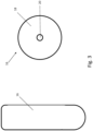
- Fig. 3 shows a wear protection element 16 in a side view and a top view.
- the wear protection element 16 has a jacket 18 and a core 20, which is at least partially radially surrounded by the jacket.
- the core 20 extends axially along the central axis of the essentially cylindrical wear protection element 16 to the upper end face of the wear protection element 16.
- the core 20 is, for example, cylindrical and is preferably firmly connected to the jacket 18. It is also conceivable that a plurality of cores 20, for example two, four or six cores 20, extend through the wear protection element 16, preferably parallel to one another.
- the diameter of the core 20 is, for example, approximately 10 to 30% of the diameter of the wear protection element 16.
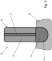
- Fig. 4 shows a sectional view of the wear protection element 16 Fig. 3 .
- the wear protection element 16 has a fastening area 24 and a wear area 22, wherein the fastening area 24 is arranged in the recess 26 on the surface of the wear surface 12 of the grinding roller and is connected to the wear surface 12 of the grinding roller.
- the wear protection element 16 is cohesively connected to the fastening area 24 with the recess 26 in the surface of the wear surface 12 of the grinding roller, in particular welded, soldered or glued or positively connected, in particular screwed or wedged.
- the wear area 22 of the wear protection element 16 is at least partially or completely arranged outside the recess 26 in the wear surface 12, so that it protrudes from the surface of the wear surface 12 in the radial direction of the grinding roller, not shown.
- the fastening area 24 comprises approximately a third of the entire wear protection element 16, with the wear area 22 approximately comprising the further two thirds.
- the fastening area 24 is preferably formed from a metal, such as steel.
- the wear area 22 of the wear protection element 16 has the jacket 18 and the core 20, the jacket 18 preferably made of a ceramic material, such as tungsten carbide, titanium carbide, titanium carbonitride, vanadium carbide, chromium carbide, tantalum carbide, boron carbide, niobium carbide, molybdenum carbide, aluminum oxide, zirconium oxide, and/or silicon carbide or a combination of the materials mentioned.
- the ceramic of the jacket comprises yttrium-stabilized, tetragonal polycrystalline zirconium oxide (TPZ), the TPZ having a volume fraction of at least 60%, preferably at least 80%, in particular 95% to 100% of the ceramic.
- TPZ yttrium-stabilized, tetragonal polycrystalline zirconium oxide
- particles made of industrial diamonds or high-strength ceramics can also be embedded in a ceramic or metallic matrix in the jacket 18.
- the jacket 18 has a matrix material in which a plurality of particles are arranged.
- the particles are in particular a highly wear-resistant material, which includes, for example, diamond, ceramic or titanium.
- the matrix material includes, for example, tungsten carbide.
- the particles are in particular bonded to the matrix material, for example by sintering.
- the wear protection elements 16 are exposed to a high level of wear, with the wear area 22 of the wear protection elements 16 protruding from the surface of the wear surfaces 12, 14 of the grinding rollers in particular wearing out.
- the wear-resistant material of the wear area 22 significantly reduces the wear of the wear protection elements 16.
- a design of the fastening area, which is exposed to no or only very little wear, is made from the more expensive, wear-resistant material is dispensed with.
- the metal core makes it possible to remove the wear protection element from the recess 26 in the roller surface, even if the wear area 22 is already heavily worn, by pulling out the wear protection element 16 on the metal core 20 using an appropriate tool.
- the fastening area 24 is preferably made entirely of metal and is firmly connected to the core 20.
- the fastening area 24 is glued, soldered or welded to the core 20 or formed in one piece with it.
Landscapes
- Engineering & Computer Science (AREA)
- Food Science & Technology (AREA)
- Crushing And Grinding (AREA)
Description
- Die Erfindung betrifft ein Verschleißschutzelement zum teilweisen Einsetzen in eine Ausnehmung an der Oberfläche einer Verschleißfläche einer Zerkleinerungseinrichtung sowie eine Zerkleinerungseinrichtung mit einem solchen Verschleißschutzelement.
- Bei Zerkleinerungseinrichtungen, wie Mahlwalzen, die insbesondere bei Gutbettzerkleinerung von beispielsweise hartem Erz zum Einsatz kommen, findet im Betrieb der Zerkleinerungseinrichtung ein hoher Verschleiß der Oberfläche einer Verschleißfläche, wie beispielsweise der Mahlwalzenoberfläche statt. Um diesem Verschleiß entgegenzuwirken, ist es beispielsweise aus der
DE 2006 010 042 A1 bekannt, zusätzliche Verschleißschutzelemente auf die Oberfläche der Mahlwalze aufzubringen. Bei einem bestimmten Verschleißgrad ist es notwendig, die Verschleißschutzelemente der Mahlwalze beispielsweise auszutauschen oder zu erneuern, um eine effiziente Mahlung zu garantieren. Insbesondere bei keramischen Verschleißschutzelementen ist der Austausch eines verschlissenen Verschleißschutzelements problematisch. Üblicherweise wird bei einem beschädigten Verschleißschutzelement durch Erhitzen die Verbindung zwischen dem Grundkörper und dem Verschleißschutzelement, wie beispielsweise Kleber, zerstört und mittels der bei der Erhitzung entstehenden Gase aus der Aussparung in dem Grundkörper, beispielsweise einem Walzenkörper, ausgetrieben oder gezogen. Bei einem keramischen Werkstoff entweichen die Gase allerdings über Risse in dem Werkstoff. Auch eine mechanische Entfernung des keramischen Verschleißschutzelements ist aufwändig, da beispielsweise das Anlöten eines Metalls zum Herausziehen des Verschleißschutzelements nicht möglich ist. Der Austausch der Verschleißschutzelemente bedingt daher häufig lange Stillstandzeiten der Walzenmühle, sowie hohe Wartungskosten. - Aus der
WO 2017/125309 A1 ist ein Verschleißschutzelement für eine Zerkleinerungseinrichtung bekannt. - Aus der
EP 3 088 084 A1 ist ein Hartkörper als Rasterpanzerung für eine Rollenpresse, ein Verfahren zu dessen Herstellung und einer Rolle für eine Rollenpresse bekannt. - Aus der
WO 2016/008967 A1 sind keramische Körner und Verfahren zu deren Herstellung bekannt. - Es ist daher die Aufgabe der vorliegenden Erfindung, ein Verschleißschutzelement bereitzustellen, das eine hohe Verschleißfestigkeit aufweist, um die Wartungsintervalle zum Austausch der Verschleißschutzelemente zu erhöhen, wobei das Verschleißschutzelement gleichzeitig kostengünstig austauschbar ist.
- Diese Aufgabe wird durch ein Verschleißschutzelement mit den Merkmalen des unabhängigen Vorrichtungsanspruchs 1 gelöst. Vorteilhafte Weiterbildungen ergeben sich aus den abhängigen Ansprüchen.
- Die Erfindung umfasst nach einem ersten Aspekt ein Verschleißschutzelement zum teilweisen Einsetzen in eine Ausnehmung an der Oberfläche einer Verschleißfläche einer Zerkleinerungseinrichtung, wobei das Verschleißschutzelement einen Befestigungsbereich, der mit der Ausnehmung in der Oberfläche der Verschleißfläche verbindbar ist und einen Verschleißbereich aufweist, der zumindest teilweise aus der Oberfläche der Verschleißfläche hervorsteht. Der Befestigungsbereich ist aus einem Metall ausgebildet. Der Verschleißbereich weist einen Mantel und einen zumindest teilweise innerhalb des Mantels angeordneten Kern auf, wobei der Kern aus einem Metall und der Mantel aus einer Keramik ausgebildet ist. Insbesondere ist der Kern vollständig innerhalb des Mantels angeordnet. Das Material des Mantels umfasst eine Keramik, die Yttrium-stabilisiertes, tetragonales polykristallines Zirconiumoxid (TPZ) aufweist, wobei das TPZ einen Volumenanteil von mindestens 60%, vorzugswiese mindestens 80%, insbesondere 95% bis 100% an der Keramik aufweist.
- Bei der Zerkleinerungseinrichtung handelt es sich beispielsweise um eine Walzenmühle, einen Walzenbrecher, eine Hammermühle oder eine Vertikalrollenmühle, wobei die Verschleißfläche insbesondere die im Betrieb der Zerkleinerungseinrichtung einem hohen Verschleiß ausgesetzte Oberfläche einer Mahlwalze, die Hammerwerkzeuge und die Oberfläche der Mahlbahn einer Hammermühle oder die Oberfläche der Rollen und des Mahltellers einer Vertikalrollenmühle ist.
- Das Verschleißschutzelement ist beispielsweise zylinderförmig ausgebildet oder weist einen vieleckigen Querschnitt auf. Insbesondere ist ein Ende des Verschleißschutzelements derart ausgebildet, dass es an der Oberfläche der Verschleißfläche, insbesondere in einer Ausnehmung in der Oberfläche der Verschleißfläche, befestigbar ist.
- Der Befestigungsbereich ist vorzugsweise derart angeordnet, dass er im Betrieb der Zerkleinerungseinrichtung keinem oder nur einem sehr geringen Verschleiß ausgesetzt ist. Insbesondere dient der Befestigungsbereich der Befestigung des Verschleißschutzelementes an der Oberfläche der Verschleißfläche. Der Verschleißbereich ist an dem Befestigungsbereich angeordnet und erstreckt sich vorzugsweise in der Höhe des Verschleißschutzelements über den Befestigungsbereich hinaus, sodass der Verschleißbereich dem Großteil des auf das Verschleißschutzelement wirkenden Verschleiß ausgesetzt ist. Der Verschleißbereich ist vorzugsweise vollständig außerhalb der Oberfläche der Verschleißfläche angebracht, wobei ausschließlich der Befestigungsbereich in der Ausnehmung der Verschleißfläche angeordnet ist. Der Befestigungsbereich und der Kern des Verschleißbereichs sind beispielsweise vollständig aus einem Metall, wie beispielsweise Stahl oder Hartmetall, wie beispielsweise Wolframcarbid, ausgebildet. Vorzugsweise ist der Mantel vollständig aus einer Keramik ausgebildet.
- Der Kern ist beispielsweise zylinderförmig ausgebildet und erstreckt sich insbesondere von dem Befestigungsbereich durch den gesamten Verschleißbereich hindurch. Es ist ebenfalls denkbar, dass der Kern einen vier- oder mehreckigen Querschnitt aufweist. Vorzugsweise erstreckt sich der Kern in axialer Richtung entlang der Mittelachse des Verschleißschutzelements durch den Verschleißbereich. Es ist ebenfalls denkbar, dass sich der Kern entlang einer Außenfläche des Verschleißelements in axialer Richtung erstreckt.
- Ein solches Verschleißschutzelement ist wesentlich kostengünstiger herstellbar, da auf die Ausbildung des gesamten Verschleißschutzelements aus dem teureren verschleißfesteren Material, wie Keramik, verzichtet werden kann. Der Bereich des Verschleißschutzelements, der keinem oder nur einem sehr geringen Verschleiß ausgesetzt ist, weist ein weniger verschleißfestes Material auf, das geringere Materialkosten bedingt. Ein Kern aus Metall in dem Verschleißbereich bietet den Vorteil, dass das verschlissene Verschleißschutzelement an diesem aus der Aussparung in der Oberfläche der Mahlwalze entfernbar ist. Zum Entfernen des Verschleißschutzelements wird dieses beispielsweise erhitzt, um eine Verbindung zwischen dem Befestigungsbereich und der Verschleißfläche der Zerkleinerungseinrichtung zu lösen. Anschließend wird das Verschleißschutzelement an dem Metallkern herausgezogen. Bei einem starken Verschleiß ist es ebenfalls denkbar, einen metallischen Werkstoff an den Metallkern durch beispielsweise Löten zu befestigen und daran das Verschleißschutzelement aus der Aussparung in der Verschleißfläche herauszuziehen.
- Gemäß einer ersten Ausführungsform erstreckt sich der Kern durch den gesamten Verschleißbereich. Dadurch ist ein Entfernen des Verschleißschutzelements unabhängig von der Stärke des Verschleißes auf einfache Weise möglich.
- Der Kern ist gemäß einer weiteren Ausführungsform mit dem Befestigungsbereich fest verbunden oder einstückig mit diesem ausgebildet. Beispielsweise ist der Befestigungsbereich mit dem Kern durch Gießen oder spanabhebendes Bearbeiten, wie Drehen oder Fräsen, hergestellt. Dadurch wird ein Entfernen des Befestigungsbereichs zusammen mit dem Verschleißbereich sichergestellt. Der Kern ist beispielsweise stoffschlüssig mit dem Befestigungsbereich verbunden, insbesondere an diesen gelötet, geklebt oder geschweißt.
- Gemäß einer weiteren Ausführungsform ist der Mantel hülsenförmig ausgebildet. Unter hülsenförmig ist insbesondere zu verstehen, dass der Mantel zylinderförmig mit einer zentralen Aussparung ausgebildet ist, wobei der Kern innerhalb der Aussparung angeordnet ist. Der Befestigungsbereich ist vorzugsweise zylinderförmigen ausgebildet und der Verschleißbereich liegt an diesem an.
- Beispielsweise umfasst das Material des Mantels einen keramischen Werkstoff, wie beispielsweise Wolframcarbid WC, Titancarbid TiC, Titancarbonitrid TiCN, Vanadiumcarbid VC, Chromcarbid CrC, Tantalcarbid TaC, Borcarbid BC, Niobcarbid NbC, Molybdäncarbid Mo2C, Aluminiumoxid AI2O3, Zirkonoxid ZrO2, und/ oder Siiliziumcarbid SiC oder eine Kombination der genannten Werkstoffe. Des Weiteren sind in dem Verschleißbereich vorzugsweise Partikel aus Industrie-Diamanten, insbesondere hochfeste Keramiken, in eine keramische oder metallische Matrix eingebettet.
- Das Material des Mantels umfasst eine Keramik, die Yttrium-stabilisiertes, tetragonales polykristallines Zirconiumoxid (TPZ) aufweist, wobei das TPZ einen Volumenanteil von mindestens 60%, vorzugswiese mindestens 80%, insbesondere 95% bis 100% an der Keramik aufweist. Dies hat den Vorteil einer erhöhten Korrosionsbeständigkeit des Materials, insbesondere bei der Nassmahlung.
- Insbesondere weist die Keramik eine Porosität von weniger als 5%, vorzugsweise weniger als 4%, insbesondere weniger als 3% auf. Vorzugsweise weist die Keramik eine Porosität von mindestens 1% auf.
- Eine Porosität von weniger als 5%, vorzugsweise weniger als 4%, insbesondere weniger als 3% führt zu einem verbesserten Verschleißverhalten. Bei den voran genannten Angaben zur Porosität handelt es sich vorzugsweise um die Gesamtporosität, die einem Mittewert der Porengrößen des Materials entspricht. Vorzugsweise sind die Poren im Wesentlichen gleichmäßig über das Keramikmaterial verteilt.
- Beispielsweise weist die Keramik eine Dichte von 1,5 bis 5 g/cm3, vorzugsweise 2 bis 4g/cm3, insbesondere 2,7 bis 3g/cm3 auf. Beispielsweise weist die Keramik einen Anteil an Al2O3 (Korund) von 10% auf. Dies führt zu einer verbesserten Verschleißfestigkeit bei gleichzeitig geringer Reduktion der Zähigkeit der Keramik.
- Die Keramik weist insbesondere ein Verhältnis von monoklinem zu tetragonalem Zirconiumoxid von weniger als 40%, insbesondere weniger als 30%, vorzugsweise weniger als 20% auf. Vorzugsweise beträgt das Verhältnis von monoklinem zu tetragonalem Zirconiumoxid wenigstens 2.% Beispielsweise weist das in der Keramik enthaltene Zirconiumoxid weniger als 40%, insbesondere weniger als 30%, vorzugsweise weniger als 20% monoklines Zirconiumoxid auf, wobei das übrige Zirconiumoxid tetragonales Zirconiumoxid ist. Das Verhältnis von monoklinem zu tetragonalem Zirconiumoxid wird beispielsweise mittels Röntgendiffraktion entsprechend der ISO 13356 bestimmt. Bei einem Verhältnis von mehr als 40%, vorzugsweise mehr als 30%, insbesondere mehr als 20% monoklinem zu tetragonalem und/oder kubischen Zirconiumoxid treten negative Effekte, wie beispielsweise eine zu schnelle Umwandlung von metastabilem Zirconiumoxid in die stabile monokline Phase auf, wobei ein Volumenzuwachs erfolgt. Bei einer zu schnellen Umwandlung entstehen Oberflächenspannungen, die beispielsweise lokale Risse hervorrufen.
- Das Yttrium-stabilisierte Zirconiumoxid der Keramik weist insbesondere eine Korngröße D50 von weniger als 1,5 µm, vorzugsweise weniger als 1µm, insbesondere weniger als 0,8µm auf. Die D50 Korngröße der Keramik weist vorzugsweise mindestens 0,2 µm auf. Unter dem D50-Wert ist die Korngröße von 50% der Körner der Keramik zu verstehen. Bei dem beispielhaften D50 Korngrößenwert weisen 50% der Körner des Yttriumstabilisierten Zirconiumoxids einen Korngrößendurchmesser von weniger als 1,5 µm, vorzugsweise weniger als 1µm, insbesondere weniger als 0,8µm auf.
- Vorzugsweise beträgt der D90-Wert der Korngröße weniger als 3µm, insbesondere weniger als 2µm, vorzugsweise weniger als 1,5µm. Verschleißschutzelemente einer Zerkleinerungseinrichtung sind lokalen Beanspruchungen ausgesetzt. Daher sollte eine breite Korngrößenverteilung vermieden werden, um die Ausbildung von Rissen oder Ausbrüchen zu verhindern.
- Insbesondere weist die Keramik einen Gehalt an Yttrium von 2 bis 4 Mol % Y2O3auf. Vorteile eines solchen Yttriumgehalts sind ein besseres Sinterverhalten bei noch niedrigere Sintertemperatur, außerdem eine feinere kristalline Struktur die wiederum zu höherer Ermüdungsresistenz und einer verbesserten Bruchzähigkeit führt. Des Weiteren weist die Keramik beispielsweise Ce-TZP mit einem Gehalt von 10 bis 12 Mol% an CeO2 auf. Insbesondere weist die Keramik einen Gehalt von 8 bis 10 mol% an Mg-PSZ auf. Es ist ebenfalls denkbar, dass die Keramik einen Gehalt von 5 bis 10 Mol % an MgO als Stabilisator aufweist.
- Die Keramik weist insbesondere eine Porenanzahl mit einer Größe von mehr als 200µm von weniger als 0,1 pro mm2 auf. Die Porenanzahl pro Fläche liefert ebenfalls einen Hinweis auf die Verschleißfestigkeit. Eine geringe Anzahl von Poren einer relativ großen Größe, wie mehr als 200µm sorgt für eine hohe Verschleißfestigkeit, da lokale Ausbrüche aus dem Keramikmaterial vermieden werden.
- Vorzugsweise weist die Keramik eine Porenanzahl mit einer Größe von mehr als 150µm von weniger als 0,4 pro mm2 auf. Insbesondere weist die Keramik eine Porenanzahl mit einer Größe von mehr als 100µm von weniger als 2 pro mm2 aufweist. Eine solche Porenanzahl erhöht die Lebensdauer des Verschleißschutzelements erheblich.
- Das Material des Befestigungsbereichs umfasst gemäß einer weiteren Ausführungsform einen Stahl, wie beispielsweise einen vergüteten Baustahl. Gemäß einer weiteren Ausführungsform ist der Mantel mit dem Befestigungsbereich fest verbunden, beispielsweise stoffschlüssig, wie Kleben oder Löten, oder formschlüssig.
- Der Befestigungsbereich umfasst gemäß einer weiteren Ausführungsform weniger als 50%, vorzugweise weniger als 20%, höchstvorzugshalber weniger als 15% des Verschleißschutzelementes. Beispielswiese umfasst der Befestigungsbereich mindestens 10% des Verschleißschutzelements.
- Die Erfindung umfasst des Weiteren eine Zerkleinerungseinrichtung aufweisend eine Verschleißfläche und ein Verschleißschutzelement wie voran beschrieben, wobei das Verschleißschutzelement zumindest teilweise in einer Ausnehmung in der Oberfläche Verschleißfläche, insbesondere einer Mahlwalze, angebracht ist.
- Die mit Bezug auf das Verschleißschutzelement beschriebenen Vorteile treffen auch auf die Zerkleinerungseinrichtung mit einem solchen Verschleißschutzelement zu.
- Der Befestigungsbereich des Verschleißschutzelements ist gemäß einer weiteren Ausführungsform mit der Mahlwalze stoffschlüssig verbunden, insbesondere geschweißt, geklebt oder gelötet. Vorzugsweise ist der Befestigungsbereich mit der Ausnehmung in der Verschleißfläche gelötet geklebt oder verschweißt.
- Die Zerkleinerungseinrichtung ist beispielsweise eine Mahlwalze zur Gutbettzerkleinerung oder eine Vertikalrollenmühle.
- Die Erfindung ist nachfolgend anhand mehrerer Ausführungsbeispiele mit Bezug auf die beiliegenden Figuren näher erläutert.
- Fig. 1
- zeigt eine schematische Darstellung einer Zerkleinerungseinrichtung in einer Frontansicht gemäß einem Ausführungsbeispiel.
- Fig. 2
- zeigt eine schematische Darstellung einer Mahlwalze der Zerkleinerungseinrichtung gemäß
Fig. 1 . - Fig. 3
- zeigt schematische Darstellungen eines Ausführungsbeispiels des Verschleißschutzelements in einer Seitenansicht und einer Draufsicht.
- Fig. 4
- zeigt schematische Darstellungen eines Ausführungsbeispiels des Verschleißschutzelements in einer Schnittansicht.
- In
Fig. 1 ist eine Zerkleinerungseinrichtung 10, insbesondere eine Walzenmühle schematisch dargestellt. Die Zerkleinerungseinrichtung 10 umfasst zwei schematisch als Kreise dargestellten Mahlwalzen mit Verschleißflächen 12, 14, die den gleichen Durchmesser aufweisen und nebeneinander angeordnet sind. Zwischen den Verschleißflächen 12, 14 der Mahlwalzen ist ein Mahlspalt ausgebildet, der beispielsweise in der Größe einstellbar ist. - Im Betrieb der Zerkleinerungseinrichtung 10 rotieren die Mahlwalzen in durch die Pfeile dargestellte Rotationsrichtung gegenläufig zueinander, wobei Mahlgut in Fallrichtung den Mahlspalt durchläuft und gemahlen wird.
-
Fig.2 zeigt einen Endbereich einer Mahlwalze, die eine Verschleißfläche 12 aufweist, an der Verschleißschutzelemente 16 angebracht sind. Die Verschleißschutzelemente 16 sind in dem äußeren Umfang der Oberfläche der Mahlwalze angebracht. Beispielhaft weisen die zueinander beabstandeten, nebeneinander angeordneten Verschleißschutzelemente 16 derFig. 2 einen kreisförmigen Querschnitt auf. Es ist ebenfalls denkbar, dass die Verschleißschutzelemente 16 über die Oberfläche der Mahlwalze in der Größe, der Anzahl, der Querschnittsform und der Anordnung zueinander variieren, um beispielsweise lokale Unterschiede der Abnutzung im Betrieb der Zerkleinerungseinrichtung 10 auszugleichen. - Ferner weist die Mahlwalze an ihrem Ende angebrachte Verschleißschutzeckelemente 17 auf, die beispielhaft einen rechteckigen Querschnitt aufweisen und in Reihe derart nebeneinander angeordnet sind, dass sie über den Umfang der Mahlwalze einen Ring ausbilden. Es sind außerdem weitere Querschnittsformen der Verschleißschutzeckelemente 17 denkbar, die von der in
Fig. 2 gezeigten Querschnittsform abweichen. Auch eine zueinander beabstandete Anordnung der Verschleißschutzeckelement 17 ist möglich. InFig. 2 ist beispielhaft nur das linke Ende der Mahlwalze mit der Verschleißfläche 12 gezeigt, wobei das nicht gezeigte rechte Ende vorteilhafterweise im Aufbau identisch ist. -
Fig. 3 zeigt ein Verschleißschutzelement 16 in einer Seitenansicht und einer Draufsicht. Das Verschleißschutzelement 16 weist einen Mantel 18 und eine Kern 20 auf, der von dem Mantel zumindest teilweise radial umgeben ist. Der Kern 20 erstreckt sich axial entlang der Mittelachse des im Wesentlichen zylinderförmigen Verschleißschutzelements 16 bis zur oberen Stirnfläche des Verschleißschutzelements 16. Der Kern 20 ist beispielhaft zylinderförmig ausgebildet und vorzugsweise fest mit dem Mantel 18 verbunden. Es ist ebenfalls denkbar, dass sich eine Mehrzahl von Kernen 20, beispielsweise zwei, vier oder sechs Kerne 20, durch das Verschleißschutzelement 16 vorzugsweise parallel zueinander erstrecken. Der Durchmesser des Kerns 20 beträgt beispielhaft etwa 10 bis 30% des Durchmessers des Verschleißschutzelements 16. -
Fig. 4 zeigt eine Schnittansicht des Verschleißschutzelements 16 derFig. 3 . Das Verschleißschutzelement 16 weist einen Befestigungsbereich 24 und einen Verschleißbereich 22 auf, wobei der Befestigungsbereich 24 in der Ausnehmung 26 an der Oberfläche des Verschleißfläche 12 der Mahlwalze angeordnet ist und mit der Verschleißfläche 12 der Mahlwalze verbunden ist. Beispielsweise ist das Verschleißschutzelement 16 an dem Befestigungsbereich 24 mit der Ausnehmung 26 in der Oberfläche der Verschleißfläche 12 der Mahlwalze stoffschlüssig, insbesondere verschweißt, verlötet oder verklebt oder formschlüssig verbunden, insbesondere verschraubt oder verkeilt. Der Verschleißbereich 22 des Verschleißschutzelements 16 ist zumindest teilweise oder vollständig außerhalb der Ausnehmung 26 in der Verschleißfläche 12 angeordnet, sodass dieser in radialer Richtung der nicht dargestellten Mahlwalze aus der Oberfläche der Verschleißfläche 12 hervorsteht. Der Befestigungsbereich 24 umfasst in dem dargestellten Ausführungsbeispiel etwa ein Drittel des gesamten Verschleißschutzelements 16, wobei der Verschleißbereich 22 in etwa die weiteren zwei Drittel umfasst. Der Befestigungsbereich 24 ist vorzugsweise aus einem Metall, wie beispielsweise Stahl ausgebildet. - Der Verschleißbereich 22 des Verschleißschutzelements 16 weist den Mantel 18 und den Kern 20 auf, wobei der Mantel 18 vorzugsweise aus einem keramischen Material, wie beispielsweise Wolframcarbid, Titancarbid, Titancarbonitrid, Vanadiumcarbid, Chromcarbid, Tantalcarbid, Borcarbid, Niobcarbid, Molybdäncarbid, Aluminiumoxid, Zirkonoxid, und/ oder Siliziumcarbid oder einer Kombination der genannten Werkstoffe ausgebildet ist. Insbesondere umfasst die Keramik des Mantels Yttrium-stabilisiertes, tetragonales polykristallines Zirconiumoxid (TPZ), wobei das TPZ einen Volumenanteil von mindestens 60%, vorzugswiese mindestens 80%, insbesondere 95% bis 100% an der Keramik aufweist.
- Des Weiteren können in dem Mantel 18 auch Partikel aus Industrie-Diamanten bzw. hochfesten Keramiken in eine keramische oder metallische Matrix eingebettet sein. Beispielsweise weist der Mantel 18 ein Matrixmaterial auf, in dem eine Mehrzahl von Partikeln angeordnet sind. Bei den Partikeln handelt es sich insbesondere um ein hochverschleißfestes Material, das beispielsweise Diamant, Keramik oder Titan umfasst. Das Matrixmaterial umfasst beispielsweise Wolframcarbid. Die Partikel sind insbesondere stoffschlüssig beispielsweise durch Sintern mit dem Matrixmaterial verbunden.
- Im Betrieb der Zerkleinerungseinrichtung 10 sind die Verschleißschutzelemente 16 einem hohen Verschleiß ausgesetzt, wobei insbesondere der aus der Oberfläche der Verschleißflächen 12, 14 der Mahlwalzen hervorstehende Verschleißbereich 22 der Verschleißschutzelemente 16 verschleißt. Das verschleißfeste Material des Verschleißbereichs 22 verringert den Verschleiß der Verschleißschutzelemente 16 erheblich. Des Weiteren wird auf eine Ausbildung des Befestigungsbereichs, der keinem oder nur einem sehr geringen Verschleiß ausgesetzt ist, aus dem teureren, verschleißfesteren Werkstoff verzichtet. Der Kern aus Metall ermöglicht es auch bei einem bereits stark verschlissenen Verschleißbereich 22, das Verschleißschutzelement aus der Ausnehmung 26 in der Walzenoberfläche zu entfernen, indem mit entsprechendem Werkzeug das Verschleißschutzelement 16 an dem Metallkern 20 herausgezogen wird.
- Der Befestigungsbereich 24 ist vorzugsweise vollständig aus einem Metall ausgebildet und fest mit dem Kern 20 verbunden. Beispielsweise ist der Befestigungsbereich 24 mit dem Kern 20 verklebt, verlötet oder verschweißt oder einstückig mit diesem ausgebildet.
-
- 10
- Zerkleinerungseinrichtung / Walzenmühle
- 12
- Verschleißfläche / Mahlwalze
- 14
- Verschleißfläche / Mahlwalze
- 16
- Verschleißschutzelement
- 17
- Verschleißschutzeckelement
- 18
- Mantel
- 20
- Kern
- 22
- Verschleißbereich
- 24
- Befestigungsbereich
- 26
- Ausnehmung
Claims (9)
- Verschleißschutzelement (16) zum teilweisen Einsetzen in eine Ausnehmung (26) in der Oberfläche einer Verschleißfläche (12, 14) einer Zerkleinerungseinrichtung (10),wobei das Verschleißschutzelement (16) einen Befestigungsbereich (24), der mit der Ausnehmung (26) in der Oberfläche der Verschleißfläche (12, 14) verbindbar ist und einen Verschleißbereich (22) aufweist, der zumindest teilweise aus der Oberfläche der Verschleißfläche (12, 14) hervorsteht, undwobei der Befestigungsbereich (24) aus einem Metall ausgebildet ist,dadurch gekennzeichnet, dassder Verschleißbereich (22) einen Mantel (18) und einen innerhalb des Mantels (18) angeordneten Kern (20) aufweist, wobei der Kern (20) aus einem Metall und der Mantel (18) aus einer Keramik (20) ausgebildet ist und wobei das Material des Mantels eine Keramik umfasst, die Yttrium-stabilisiertes, tetragonales polykristallines Zirconiumoxid (TPZ) aufweist, wobei das TPZ einen Volumenanteil von mindestens 60%, vorzugswiese mindestens 80%, insbesondere 95% bis 100% an der Keramik aufweist.
- Verschleißschutzelement (16) nach Anspruch 1, wobei sich der Kern (20) durch den gesamten Verschleißbereich erstreckt.
- Verschleißschutzelement (16) nach einem der vorangehenden Ansprüche, wobei der Kern (20) mit dem Befestigungsbereich (24) fest verbunden oder einstückig mit diesem ausgebildet ist.
- Verschleißschutzelement (16) nach einem der vorangehenden Ansprüche, wobei der Mantel (18) hülsenförmig ausgebildet ist.
- Verschleißschutzelement (16) nach einem der vorangehenden Ansprüche, wobei das Material des Befestigungsbereichs (24) einen Stahl umfasst.
- Verschleißschutzelement (16) nach einem der vorangehenden Ansprüche, wobei der Mantel des Verschleißbereichs (22) mit dem Befestigungsbereich fest verbunden ist.
- Verschleißschutzelement (16) nach einem der vorangehenden Ansprüche, wobei der Befestigungsbereich (24) weniger als 50%, vorzugweise weniger als 20%, höchstvorzugshalber weniger als 15% des Verschleißschutzelementes (16) umfasst.
- Zerkleinerungseinrichtung (10) aufweisend eine Verschleißfläche (12, 14) und ein Verschleißschutzelement (16) nach einem der Ansprüche 1 bis 7, wobei das Verschleißschutzelement (16) zumindest teilweise in einer Ausnehmung (26) in der Oberfläche der Verschleißfläche (12, 14) angebracht ist.
- Zerkleinerungseinrichtung (10) nach Anspruch 8, wobei der Befestigungsbereich (24) des Verschleißschutzelements (16) mit der Verschleißfläche / Mahlwalze (12, 14) stoffschlüssig verbunden, insbesondere geschweißt, geklebt oder gelötet ist.
Applications Claiming Priority (3)
| Application Number | Priority Date | Filing Date | Title |
|---|---|---|---|
| DE102019218219.4A DE102019218219A1 (de) | 2019-11-26 | 2019-11-26 | Verschleißschutzelement für eine Zerkleinerungseinrichtung |
| BE20195840A BE1027797B1 (de) | 2019-11-26 | 2019-11-26 | Verschleißschutzelement für eine Zerkleinerungseinrichtung |
| PCT/EP2020/083409 WO2021105237A1 (de) | 2019-11-26 | 2020-11-25 | VERSCHLEIßSCHUTZELEMENT FÜR EINE ZERKLEINERUNGSEINRICHTUNG |
Publications (2)
| Publication Number | Publication Date |
|---|---|
| EP4065282A1 EP4065282A1 (de) | 2022-10-05 |
| EP4065282B1 true EP4065282B1 (de) | 2023-12-13 |
Family
ID=73497796
Family Applications (1)
| Application Number | Title | Priority Date | Filing Date |
|---|---|---|---|
| EP20810984.3A Active EP4065282B1 (de) | 2019-11-26 | 2020-11-25 | Verschleissschutzelement für eine zerkleinerungseinrichtung |
Country Status (6)
| Country | Link |
|---|---|
| US (1) | US12172172B2 (de) |
| EP (1) | EP4065282B1 (de) |
| CN (1) | CN114206504B (de) |
| DK (1) | DK4065282T3 (de) |
| FI (1) | FI4065282T3 (de) |
| WO (1) | WO2021105237A1 (de) |
Citations (2)
| Publication number | Priority date | Publication date | Assignee | Title |
|---|---|---|---|---|
| EP3088084B1 (de) * | 2015-04-29 | 2017-11-22 | Takraf GmbH | Hartkörper als rasterpanzerung für eine rollenpresse, verfahren zu dessen herstellung, und rolle für eine rollenpresse |
| EP2512680B1 (de) * | 2009-12-18 | 2019-01-02 | Metso Sweden AB | Länglicher aus zwei materialien bestehender einsatz für zerkleinerungsrolle |
Family Cites Families (27)
| Publication number | Priority date | Publication date | Assignee | Title |
|---|---|---|---|---|
| JPS63143949A (ja) * | 1986-12-09 | 1988-06-16 | アイエヌジ商事株式会社 | 粉砕機に使用される破砕面部材 |
| DE4132474A1 (de) * | 1991-05-28 | 1992-12-03 | Kloeckner Humboldt Deutz Ag | Verschleissfeste mahlwalze fuer die verwendung in walzenmaschinen, insbesondere in hochdruckwalzenpressen |
| DE4431563A1 (de) * | 1994-09-05 | 1996-03-07 | Kloeckner Humboldt Deutz Ag | Verschleißfeste Oberflächenpanzerung für die Walzen von Hochdruck-Walzenpressen zur Druckzerkleinerung körnigen Gutes (Unterlagen zu P 44 44 337.4 gegeben) |
| DE19638237A1 (de) * | 1996-09-19 | 1998-03-26 | Deutz Ag | Verschleißfeste Oberflächenpanzerung für die Walzen von Hochdruck-Walzenpressen zur Druckzerkleinerung körnigen Gutes |
| HU224208B1 (hu) * | 1996-10-01 | 2005-06-28 | Magotteaux International S.A. | Összetett anyagú kopásálló alkatrész |
| DE10335115A1 (de) * | 2003-07-31 | 2005-02-24 | Polysius Ag | Mahlwalze |
| FI118518B (fi) * | 2006-01-25 | 2007-12-14 | Metso Powdermet Oy | Menetelmä monimateriaalikomponentin tai -rakenteen valmistamiseksi sekä monimateriaalikomponentin tai -rakenteen käyttö |
| DE102006010042A1 (de) | 2006-03-04 | 2007-09-06 | Khd Humboldt Wedag Gmbh | Hartkörper für den autogenen Verschleißschutz von Walzenoberflächen |
| DE102006014874A1 (de) * | 2006-03-30 | 2007-10-04 | Wacker Chemie Ag | Vorrichtung und Verfahren zum Zerkleinern von grobteilig gebrochenem polykristallinem Silicium |
| US7669674B2 (en) * | 2006-08-11 | 2010-03-02 | Hall David R | Degradation assembly |
| US8147980B2 (en) * | 2006-11-01 | 2012-04-03 | Aia Engineering, Ltd. | Wear-resistant metal matrix ceramic composite parts and methods of manufacturing thereof |
| US7523794B2 (en) * | 2006-12-18 | 2009-04-28 | Hall David R | Wear resistant assembly |
| US20110003083A1 (en) * | 2009-04-13 | 2011-01-06 | Quanzu Yang | Method for making functional ceramic films on ceramic materials |
| US8420201B2 (en) * | 2009-07-09 | 2013-04-16 | Scoperta, Inc. | Wear-resistant attachments for high-wear applications |
| DE102009050636B4 (de) * | 2009-10-24 | 2011-07-07 | Siempelkamp Giesserei GmbH, 47803 | Mahlwalze und Ringbandage für eine Mahlwalze |
| WO2011064685A1 (en) * | 2009-11-25 | 2011-06-03 | Flsmidth A/S | Wear -resistant roller for crushing and method for producing the same |
| DE202010013735U1 (de) * | 2010-09-29 | 2012-01-13 | Maschinenfabrik Köppern GmbH & Co KG | Walzenpresse |
| JP5760384B2 (ja) * | 2010-10-28 | 2015-08-12 | 三菱マテリアル株式会社 | 多結晶シリコンの破砕装置及び多結晶シリコン破砕物の製造方法 |
| PE20141153A1 (es) * | 2010-12-29 | 2014-09-16 | Smidth As F L | Elemento de trituracion y metodo para hacer el mismo |
| DE102011104854B4 (de) * | 2011-06-21 | 2015-06-11 | Khd Humboldt Wedag Gmbh | Mahlwalze mit in die Oberfläche eingesetzten Hartkörpern |
| EP2991769B1 (de) * | 2013-05-01 | 2020-06-17 | US Synthetic Corporation | Rollenanordnungen mit superharten einsätzen, hochdruck-schleifwalzenvorrichtungen damit und verfahren zur verwendung |
| DE102013106738A1 (de) * | 2013-06-27 | 2014-12-31 | Thyssenkrupp Industrial Solutions Ag | Zerkleinerungsaggregat sowie Verfahren zum Bestücken einer Umfangs- oder Oberfläche eines Zerkleinerungsaggregates mit Profilkörpern |
| BE1021335B1 (fr) * | 2014-07-16 | 2015-11-03 | Magotteaux International S.A. | Grains ceramiques et procede pour leur production. |
| DE102016200911A1 (de) * | 2016-01-22 | 2017-07-27 | Thyssenkrupp Ag | Verschleißschutzelement für eine Zerkleinerungseinrichtung |
| DE102016200912A1 (de) | 2016-01-22 | 2017-07-27 | Thyssenkrupp Ag | Verschleißschutzelement für eine Zerkleinerungseinrichtung |
| CN106000565B (zh) * | 2016-05-13 | 2018-05-29 | 东莞市煜田新材料有限公司 | 陶瓷内定子 |
| CN106513107A (zh) * | 2016-11-15 | 2017-03-22 | 昆明理工大学 | 一种复合挤压辊及其制备方法 |
-
2020
- 2020-11-25 DK DK20810984.3T patent/DK4065282T3/da active
- 2020-11-25 CN CN202080053588.0A patent/CN114206504B/zh active Active
- 2020-11-25 FI FIEP20810984.3T patent/FI4065282T3/fi active
- 2020-11-25 EP EP20810984.3A patent/EP4065282B1/de active Active
- 2020-11-25 US US17/780,152 patent/US12172172B2/en active Active
- 2020-11-25 WO PCT/EP2020/083409 patent/WO2021105237A1/de not_active Ceased
Patent Citations (2)
| Publication number | Priority date | Publication date | Assignee | Title |
|---|---|---|---|---|
| EP2512680B1 (de) * | 2009-12-18 | 2019-01-02 | Metso Sweden AB | Länglicher aus zwei materialien bestehender einsatz für zerkleinerungsrolle |
| EP3088084B1 (de) * | 2015-04-29 | 2017-11-22 | Takraf GmbH | Hartkörper als rasterpanzerung für eine rollenpresse, verfahren zu dessen herstellung, und rolle für eine rollenpresse |
Also Published As
| Publication number | Publication date |
|---|---|
| CN114206504B (zh) | 2024-07-05 |
| EP4065282A1 (de) | 2022-10-05 |
| CN114206504A (zh) | 2022-03-18 |
| WO2021105237A1 (de) | 2021-06-03 |
| US20220410168A1 (en) | 2022-12-29 |
| US12172172B2 (en) | 2024-12-24 |
| DK4065282T3 (da) | 2024-01-15 |
| FI4065282T3 (fi) | 2024-01-12 |
Similar Documents
| Publication | Publication Date | Title |
|---|---|---|
| EP3405287B1 (de) | Verschleissschutzelement für eine zerkleinerungseinrichtung | |
| DE68919908T2 (de) | Schleifscheibe mit hoher Schlagfestigkeit zum in-situ-Schleifen von Rollen. | |
| EP0405518A2 (de) | Mahlfläche von Wälzmühlen | |
| DE4039217A1 (de) | Rundschaftmeissel | |
| EP3405286B1 (de) | Verschleissschutzelement für eine zerkleinerungseinrichtung | |
| DE102012102192A1 (de) | Presswalze für eine Walzenpresse | |
| WO2007096215A1 (de) | Mahlwerkzeug mit einer beschichtung | |
| DE102012102199A1 (de) | Presswalze | |
| EP3658286B1 (de) | Brecher mit einem verschleisselement und ein verfahren zum herstellen eines verschleisselements eines brechers | |
| DE60012320T2 (de) | Drehendes werkzeug mit kombinierter schleif- und bruchwirkung zum erzeugen von profilen oder schnitten auf platten aus zerbrechlichen materialen sowie marmor, granit, stein | |
| DE102019218219A1 (de) | Verschleißschutzelement für eine Zerkleinerungseinrichtung | |
| WO2019020525A1 (de) | Brechwalze mit einem brechwerkzeug | |
| EP4065281B1 (de) | Verschleissschutzelement für eine zerkleinerungseinrichtung | |
| BE1027797B1 (de) | Verschleißschutzelement für eine Zerkleinerungseinrichtung | |
| DE2608883A1 (de) | Prallhammermuehle | |
| BE1027796B1 (de) | Verschleißschutzelement für eine Zerkleinerungseinrichtung | |
| WO2021105237A1 (de) | VERSCHLEIßSCHUTZELEMENT FÜR EINE ZERKLEINERUNGSEINRICHTUNG | |
| DE102019218217A1 (de) | Verschleißschutzelement für eine Zerkleinerungseinrichtung | |
| EP0614726B1 (de) | Schleifgerät, insbesondere zum Abstärken von Beton und Natursteinen | |
| DE19721637A1 (de) | Brechbacke zur Ausrüstung eines Backenbrechers, insbesondere für verschleißarmes Zerkleinern von Naturgestein oder Bauschutt | |
| DE102019201097B4 (de) | Verschleißschutzelement für eine Zerkleinerungsvorrichtung und Verwendung | |
| DE102013004560A1 (de) | Papierschneidmesser | |
| WO2020156949A1 (de) | VERSCHLEIßSCHUTZELEMENT FÜR EINE ZERKLEINERUNGSVORRICHTUNG | |
| EP1616464B1 (de) | Düse für plasmabrenner | |
| EP1888285B1 (de) | Schleifwerkzeug |
Legal Events
| Date | Code | Title | Description |
|---|---|---|---|
| STAA | Information on the status of an ep patent application or granted ep patent |
Free format text: STATUS: UNKNOWN |
|
| STAA | Information on the status of an ep patent application or granted ep patent |
Free format text: STATUS: THE INTERNATIONAL PUBLICATION HAS BEEN MADE |
|
| PUAI | Public reference made under article 153(3) epc to a published international application that has entered the european phase |
Free format text: ORIGINAL CODE: 0009012 |
|
| STAA | Information on the status of an ep patent application or granted ep patent |
Free format text: STATUS: REQUEST FOR EXAMINATION WAS MADE |
|
| 17P | Request for examination filed |
Effective date: 20220627 |
|
| AK | Designated contracting states |
Kind code of ref document: A1 Designated state(s): AL AT BE BG CH CY CZ DE DK EE ES FI FR GB GR HR HU IE IS IT LI LT LU LV MC MK MT NL NO PL PT RO RS SE SI SK SM TR |
|
| RAP3 | Party data changed (applicant data changed or rights of an application transferred) |
Owner name: THYSSENKRUPP INDUSTRIAL SOLUTIONS AG |
|
| RAP1 | Party data changed (applicant data changed or rights of an application transferred) |
Owner name: FLSMIDTH A/S |
|
| DAV | Request for validation of the european patent (deleted) | ||
| DAX | Request for extension of the european patent (deleted) | ||
| GRAP | Despatch of communication of intention to grant a patent |
Free format text: ORIGINAL CODE: EPIDOSNIGR1 |
|
| STAA | Information on the status of an ep patent application or granted ep patent |
Free format text: STATUS: GRANT OF PATENT IS INTENDED |
|
| INTG | Intention to grant announced |
Effective date: 20230802 |
|
| GRAS | Grant fee paid |
Free format text: ORIGINAL CODE: EPIDOSNIGR3 |
|
| GRAA | (expected) grant |
Free format text: ORIGINAL CODE: 0009210 |
|
| STAA | Information on the status of an ep patent application or granted ep patent |
Free format text: STATUS: THE PATENT HAS BEEN GRANTED |
|
| AK | Designated contracting states |
Kind code of ref document: B1 Designated state(s): AL AT BE BG CH CY CZ DE DK EE ES FI FR GB GR HR HU IE IS IT LI LT LU LV MC MK MT NL NO PL PT RO RS SE SI SK SM TR |
|
| REG | Reference to a national code |
Ref country code: GB Ref legal event code: FG4D Free format text: NOT ENGLISH |
|
| REG | Reference to a national code |
Ref country code: CH Ref legal event code: EP |
|
| REG | Reference to a national code |
Ref country code: DE Ref legal event code: R096 Ref document number: 502020006406 Country of ref document: DE |
|
| P01 | Opt-out of the competence of the unified patent court (upc) registered |
Effective date: 20231122 |
|
| REG | Reference to a national code |
Ref country code: IE Ref legal event code: FG4D Free format text: LANGUAGE OF EP DOCUMENT: GERMAN |
|
| REG | Reference to a national code |
Ref country code: FI Ref legal event code: FGE |
|
| REG | Reference to a national code |
Ref country code: DK Ref legal event code: T3 Effective date: 20240110 |
|
| REG | Reference to a national code |
Ref country code: NL Ref legal event code: FP |
|
| REG | Reference to a national code |
Ref country code: SE Ref legal event code: TRGR |
|
| PG25 | Lapsed in a contracting state [announced via postgrant information from national office to epo] |
Ref country code: GR Free format text: LAPSE BECAUSE OF FAILURE TO SUBMIT A TRANSLATION OF THE DESCRIPTION OR TO PAY THE FEE WITHIN THE PRESCRIBED TIME-LIMIT Effective date: 20240314 |
|
| REG | Reference to a national code |
Ref country code: LT Ref legal event code: MG9D |
|
| PG25 | Lapsed in a contracting state [announced via postgrant information from national office to epo] |
Ref country code: LT Free format text: LAPSE BECAUSE OF FAILURE TO SUBMIT A TRANSLATION OF THE DESCRIPTION OR TO PAY THE FEE WITHIN THE PRESCRIBED TIME-LIMIT Effective date: 20231213 |
|
| PG25 | Lapsed in a contracting state [announced via postgrant information from national office to epo] |
Ref country code: ES Free format text: LAPSE BECAUSE OF FAILURE TO SUBMIT A TRANSLATION OF THE DESCRIPTION OR TO PAY THE FEE WITHIN THE PRESCRIBED TIME-LIMIT Effective date: 20231213 |
|
| PG25 | Lapsed in a contracting state [announced via postgrant information from national office to epo] |
Ref country code: LT Free format text: LAPSE BECAUSE OF FAILURE TO SUBMIT A TRANSLATION OF THE DESCRIPTION OR TO PAY THE FEE WITHIN THE PRESCRIBED TIME-LIMIT Effective date: 20231213 Ref country code: GR Free format text: LAPSE BECAUSE OF FAILURE TO SUBMIT A TRANSLATION OF THE DESCRIPTION OR TO PAY THE FEE WITHIN THE PRESCRIBED TIME-LIMIT Effective date: 20240314 Ref country code: ES Free format text: LAPSE BECAUSE OF FAILURE TO SUBMIT A TRANSLATION OF THE DESCRIPTION OR TO PAY THE FEE WITHIN THE PRESCRIBED TIME-LIMIT Effective date: 20231213 Ref country code: BG Free format text: LAPSE BECAUSE OF FAILURE TO SUBMIT A TRANSLATION OF THE DESCRIPTION OR TO PAY THE FEE WITHIN THE PRESCRIBED TIME-LIMIT Effective date: 20240313 |
|
| PG25 | Lapsed in a contracting state [announced via postgrant information from national office to epo] |
Ref country code: RS Free format text: LAPSE BECAUSE OF FAILURE TO SUBMIT A TRANSLATION OF THE DESCRIPTION OR TO PAY THE FEE WITHIN THE PRESCRIBED TIME-LIMIT Effective date: 20231213 Ref country code: NO Free format text: LAPSE BECAUSE OF FAILURE TO SUBMIT A TRANSLATION OF THE DESCRIPTION OR TO PAY THE FEE WITHIN THE PRESCRIBED TIME-LIMIT Effective date: 20240313 Ref country code: LV Free format text: LAPSE BECAUSE OF FAILURE TO SUBMIT A TRANSLATION OF THE DESCRIPTION OR TO PAY THE FEE WITHIN THE PRESCRIBED TIME-LIMIT Effective date: 20231213 Ref country code: HR Free format text: LAPSE BECAUSE OF FAILURE TO SUBMIT A TRANSLATION OF THE DESCRIPTION OR TO PAY THE FEE WITHIN THE PRESCRIBED TIME-LIMIT Effective date: 20231213 |
|
| PG25 | Lapsed in a contracting state [announced via postgrant information from national office to epo] |
Ref country code: IS Free format text: LAPSE BECAUSE OF FAILURE TO SUBMIT A TRANSLATION OF THE DESCRIPTION OR TO PAY THE FEE WITHIN THE PRESCRIBED TIME-LIMIT Effective date: 20240413 |
|
| PG25 | Lapsed in a contracting state [announced via postgrant information from national office to epo] |
Ref country code: CZ Free format text: LAPSE BECAUSE OF FAILURE TO SUBMIT A TRANSLATION OF THE DESCRIPTION OR TO PAY THE FEE WITHIN THE PRESCRIBED TIME-LIMIT Effective date: 20231213 |
|
| PG25 | Lapsed in a contracting state [announced via postgrant information from national office to epo] |
Ref country code: SK Free format text: LAPSE BECAUSE OF FAILURE TO SUBMIT A TRANSLATION OF THE DESCRIPTION OR TO PAY THE FEE WITHIN THE PRESCRIBED TIME-LIMIT Effective date: 20231213 |
|
| PG25 | Lapsed in a contracting state [announced via postgrant information from national office to epo] |
Ref country code: SM Free format text: LAPSE BECAUSE OF FAILURE TO SUBMIT A TRANSLATION OF THE DESCRIPTION OR TO PAY THE FEE WITHIN THE PRESCRIBED TIME-LIMIT Effective date: 20231213 Ref country code: SK Free format text: LAPSE BECAUSE OF FAILURE TO SUBMIT A TRANSLATION OF THE DESCRIPTION OR TO PAY THE FEE WITHIN THE PRESCRIBED TIME-LIMIT Effective date: 20231213 Ref country code: RO Free format text: LAPSE BECAUSE OF FAILURE TO SUBMIT A TRANSLATION OF THE DESCRIPTION OR TO PAY THE FEE WITHIN THE PRESCRIBED TIME-LIMIT Effective date: 20231213 Ref country code: IT Free format text: LAPSE BECAUSE OF FAILURE TO SUBMIT A TRANSLATION OF THE DESCRIPTION OR TO PAY THE FEE WITHIN THE PRESCRIBED TIME-LIMIT Effective date: 20231213 Ref country code: IS Free format text: LAPSE BECAUSE OF FAILURE TO SUBMIT A TRANSLATION OF THE DESCRIPTION OR TO PAY THE FEE WITHIN THE PRESCRIBED TIME-LIMIT Effective date: 20240413 Ref country code: EE Free format text: LAPSE BECAUSE OF FAILURE TO SUBMIT A TRANSLATION OF THE DESCRIPTION OR TO PAY THE FEE WITHIN THE PRESCRIBED TIME-LIMIT Effective date: 20231213 Ref country code: CZ Free format text: LAPSE BECAUSE OF FAILURE TO SUBMIT A TRANSLATION OF THE DESCRIPTION OR TO PAY THE FEE WITHIN THE PRESCRIBED TIME-LIMIT Effective date: 20231213 |
|
| PG25 | Lapsed in a contracting state [announced via postgrant information from national office to epo] |
Ref country code: PL Free format text: LAPSE BECAUSE OF FAILURE TO SUBMIT A TRANSLATION OF THE DESCRIPTION OR TO PAY THE FEE WITHIN THE PRESCRIBED TIME-LIMIT Effective date: 20231213 Ref country code: PT Free format text: LAPSE BECAUSE OF FAILURE TO SUBMIT A TRANSLATION OF THE DESCRIPTION OR TO PAY THE FEE WITHIN THE PRESCRIBED TIME-LIMIT Effective date: 20240415 |
|
| PG25 | Lapsed in a contracting state [announced via postgrant information from national office to epo] |
Ref country code: PT Free format text: LAPSE BECAUSE OF FAILURE TO SUBMIT A TRANSLATION OF THE DESCRIPTION OR TO PAY THE FEE WITHIN THE PRESCRIBED TIME-LIMIT Effective date: 20240415 Ref country code: PL Free format text: LAPSE BECAUSE OF FAILURE TO SUBMIT A TRANSLATION OF THE DESCRIPTION OR TO PAY THE FEE WITHIN THE PRESCRIBED TIME-LIMIT Effective date: 20231213 |
|
| REG | Reference to a national code |
Ref country code: DE Ref legal event code: R097 Ref document number: 502020006406 Country of ref document: DE |
|
| PLBE | No opposition filed within time limit |
Free format text: ORIGINAL CODE: 0009261 |
|
| STAA | Information on the status of an ep patent application or granted ep patent |
Free format text: STATUS: NO OPPOSITION FILED WITHIN TIME LIMIT |
|
| PG25 | Lapsed in a contracting state [announced via postgrant information from national office to epo] |
Ref country code: SI Free format text: LAPSE BECAUSE OF FAILURE TO SUBMIT A TRANSLATION OF THE DESCRIPTION OR TO PAY THE FEE WITHIN THE PRESCRIBED TIME-LIMIT Effective date: 20231213 |
|
| PG25 | Lapsed in a contracting state [announced via postgrant information from national office to epo] |
Ref country code: SI Free format text: LAPSE BECAUSE OF FAILURE TO SUBMIT A TRANSLATION OF THE DESCRIPTION OR TO PAY THE FEE WITHIN THE PRESCRIBED TIME-LIMIT Effective date: 20231213 |
|
| 26N | No opposition filed |
Effective date: 20240916 |
|
| REG | Reference to a national code |
Ref country code: CH Ref legal event code: PL |
|
| PG25 | Lapsed in a contracting state [announced via postgrant information from national office to epo] |
Ref country code: MC Free format text: LAPSE BECAUSE OF FAILURE TO SUBMIT A TRANSLATION OF THE DESCRIPTION OR TO PAY THE FEE WITHIN THE PRESCRIBED TIME-LIMIT Effective date: 20231213 |
|
| PG25 | Lapsed in a contracting state [announced via postgrant information from national office to epo] |
Ref country code: LU Free format text: LAPSE BECAUSE OF NON-PAYMENT OF DUE FEES Effective date: 20241125 |
|
| REG | Reference to a national code |
Ref country code: CH Ref legal event code: PL |
|
| GBPC | Gb: european patent ceased through non-payment of renewal fee |
Effective date: 20241125 |
|
| PG25 | Lapsed in a contracting state [announced via postgrant information from national office to epo] |
Ref country code: CH Free format text: LAPSE BECAUSE OF NON-PAYMENT OF DUE FEES Effective date: 20241130 |
|
| REG | Reference to a national code |
Ref country code: BE Ref legal event code: MM Effective date: 20241130 |
|
| PG25 | Lapsed in a contracting state [announced via postgrant information from national office to epo] |
Ref country code: BE Free format text: LAPSE BECAUSE OF NON-PAYMENT OF DUE FEES Effective date: 20241130 Ref country code: GB Free format text: LAPSE BECAUSE OF NON-PAYMENT OF DUE FEES Effective date: 20241125 |
|
| PG25 | Lapsed in a contracting state [announced via postgrant information from national office to epo] |
Ref country code: FR Free format text: LAPSE BECAUSE OF NON-PAYMENT OF DUE FEES Effective date: 20241130 |
|
| PG25 | Lapsed in a contracting state [announced via postgrant information from national office to epo] |
Ref country code: IE Free format text: LAPSE BECAUSE OF NON-PAYMENT OF DUE FEES Effective date: 20241125 |
|
| PGFP | Annual fee paid to national office [announced via postgrant information from national office to epo] |
Ref country code: NL Payment date: 20251124 Year of fee payment: 6 |
|
| PGFP | Annual fee paid to national office [announced via postgrant information from national office to epo] |
Ref country code: DE Payment date: 20251126 Year of fee payment: 6 |
|
| PGFP | Annual fee paid to national office [announced via postgrant information from national office to epo] |
Ref country code: AT Payment date: 20260113 Year of fee payment: 5 |
|
| PGFP | Annual fee paid to national office [announced via postgrant information from national office to epo] |
Ref country code: FI Payment date: 20251124 Year of fee payment: 6 Ref country code: DK Payment date: 20251124 Year of fee payment: 6 |
|
| PGFP | Annual fee paid to national office [announced via postgrant information from national office to epo] |
Ref country code: SE Payment date: 20251124 Year of fee payment: 6 |
|
| PG25 | Lapsed in a contracting state [announced via postgrant information from national office to epo] |
Ref country code: HU Free format text: LAPSE BECAUSE OF FAILURE TO SUBMIT A TRANSLATION OF THE DESCRIPTION OR TO PAY THE FEE WITHIN THE PRESCRIBED TIME-LIMIT; INVALID AB INITIO Effective date: 20201125 |
|
| PG25 | Lapsed in a contracting state [announced via postgrant information from national office to epo] |
Ref country code: CY Free format text: LAPSE BECAUSE OF FAILURE TO SUBMIT A TRANSLATION OF THE DESCRIPTION OR TO PAY THE FEE WITHIN THE PRESCRIBED TIME-LIMIT; INVALID AB INITIO Effective date: 20201125 |