EP4065010B1 - Ultraschallsondenanordnung und system - Google Patents
Ultraschallsondenanordnung und system Download PDFInfo
- Publication number
- EP4065010B1 EP4065010B1 EP19821414.0A EP19821414A EP4065010B1 EP 4065010 B1 EP4065010 B1 EP 4065010B1 EP 19821414 A EP19821414 A EP 19821414A EP 4065010 B1 EP4065010 B1 EP 4065010B1
- Authority
- EP
- European Patent Office
- Prior art keywords
- ultrasonic
- catheter
- mode
- ultrasonic transducer
- atherectomy
- Prior art date
- Legal status (The legal status is an assumption and is not a legal conclusion. Google has not performed a legal analysis and makes no representation as to the accuracy of the status listed.)
- Active
Links
Images

Classifications
-
- A—HUMAN NECESSITIES
- A61—MEDICAL OR VETERINARY SCIENCE; HYGIENE
- A61B—DIAGNOSIS; SURGERY; IDENTIFICATION
- A61B17/00—Surgical instruments, devices or methods
- A61B17/22—Implements for squeezing-off ulcers or the like on inner organs of the body; Implements for scraping-out cavities of body organs, e.g. bones; for invasive removal or destruction of calculus using mechanical vibrations; for removing obstructions in blood vessels, not otherwise provided for
- A61B17/22004—Implements for squeezing-off ulcers or the like on inner organs of the body; Implements for scraping-out cavities of body organs, e.g. bones; for invasive removal or destruction of calculus using mechanical vibrations; for removing obstructions in blood vessels, not otherwise provided for using mechanical vibrations, e.g. ultrasonic shock waves
- A61B17/22012—Implements for squeezing-off ulcers or the like on inner organs of the body; Implements for scraping-out cavities of body organs, e.g. bones; for invasive removal or destruction of calculus using mechanical vibrations; for removing obstructions in blood vessels, not otherwise provided for using mechanical vibrations, e.g. ultrasonic shock waves in direct contact with, or very close to, the obstruction or concrement
-
- A—HUMAN NECESSITIES
- A61—MEDICAL OR VETERINARY SCIENCE; HYGIENE
- A61B—DIAGNOSIS; SURGERY; IDENTIFICATION
- A61B17/00—Surgical instruments, devices or methods
- A61B17/22—Implements for squeezing-off ulcers or the like on inner organs of the body; Implements for scraping-out cavities of body organs, e.g. bones; for invasive removal or destruction of calculus using mechanical vibrations; for removing obstructions in blood vessels, not otherwise provided for
-
- A—HUMAN NECESSITIES
- A61—MEDICAL OR VETERINARY SCIENCE; HYGIENE
- A61B—DIAGNOSIS; SURGERY; IDENTIFICATION
- A61B17/00—Surgical instruments, devices or methods
- A61B17/32—Surgical cutting instruments
-
- A—HUMAN NECESSITIES
- A61—MEDICAL OR VETERINARY SCIENCE; HYGIENE
- A61B—DIAGNOSIS; SURGERY; IDENTIFICATION
- A61B17/00—Surgical instruments, devices or methods
- A61B17/32—Surgical cutting instruments
- A61B17/320068—Surgical cutting instruments using mechanical vibrations, e.g. ultrasonic
-
- A—HUMAN NECESSITIES
- A61—MEDICAL OR VETERINARY SCIENCE; HYGIENE
- A61B—DIAGNOSIS; SURGERY; IDENTIFICATION
- A61B17/00—Surgical instruments, devices or methods
- A61B17/22—Implements for squeezing-off ulcers or the like on inner organs of the body; Implements for scraping-out cavities of body organs, e.g. bones; for invasive removal or destruction of calculus using mechanical vibrations; for removing obstructions in blood vessels, not otherwise provided for
- A61B17/22004—Implements for squeezing-off ulcers or the like on inner organs of the body; Implements for scraping-out cavities of body organs, e.g. bones; for invasive removal or destruction of calculus using mechanical vibrations; for removing obstructions in blood vessels, not otherwise provided for using mechanical vibrations, e.g. ultrasonic shock waves
- A61B17/22012—Implements for squeezing-off ulcers or the like on inner organs of the body; Implements for scraping-out cavities of body organs, e.g. bones; for invasive removal or destruction of calculus using mechanical vibrations; for removing obstructions in blood vessels, not otherwise provided for using mechanical vibrations, e.g. ultrasonic shock waves in direct contact with, or very close to, the obstruction or concrement
- A61B2017/22014—Implements for squeezing-off ulcers or the like on inner organs of the body; Implements for scraping-out cavities of body organs, e.g. bones; for invasive removal or destruction of calculus using mechanical vibrations; for removing obstructions in blood vessels, not otherwise provided for using mechanical vibrations, e.g. ultrasonic shock waves in direct contact with, or very close to, the obstruction or concrement the ultrasound transducer being outside patient's body; with an ultrasound transmission member; with a wave guide; with a vibrated guide wire
-
- A—HUMAN NECESSITIES
- A61—MEDICAL OR VETERINARY SCIENCE; HYGIENE
- A61B—DIAGNOSIS; SURGERY; IDENTIFICATION
- A61B17/00—Surgical instruments, devices or methods
- A61B17/22—Implements for squeezing-off ulcers or the like on inner organs of the body; Implements for scraping-out cavities of body organs, e.g. bones; for invasive removal or destruction of calculus using mechanical vibrations; for removing obstructions in blood vessels, not otherwise provided for
- A61B2017/22072—Implements for squeezing-off ulcers or the like on inner organs of the body; Implements for scraping-out cavities of body organs, e.g. bones; for invasive removal or destruction of calculus using mechanical vibrations; for removing obstructions in blood vessels, not otherwise provided for with an instrument channel, e.g. for replacing one instrument by the other
- A61B2017/22074—Implements for squeezing-off ulcers or the like on inner organs of the body; Implements for scraping-out cavities of body organs, e.g. bones; for invasive removal or destruction of calculus using mechanical vibrations; for removing obstructions in blood vessels, not otherwise provided for with an instrument channel, e.g. for replacing one instrument by the other the instrument being only slidable in a channel, e.g. advancing optical fibre through a channel
-
- A—HUMAN NECESSITIES
- A61—MEDICAL OR VETERINARY SCIENCE; HYGIENE
- A61B—DIAGNOSIS; SURGERY; IDENTIFICATION
- A61B17/00—Surgical instruments, devices or methods
- A61B17/32—Surgical cutting instruments
- A61B17/320068—Surgical cutting instruments using mechanical vibrations, e.g. ultrasonic
- A61B2017/320069—Surgical cutting instruments using mechanical vibrations, e.g. ultrasonic for ablating tissue
Definitions
- the present invention relates to an ultrasonic system, and more particularly, to an ultrasonic probe assembly and system that may be used for occlusion engagement during crossing and atherectomy procedures.
- Vascular procedures such as a crossing procedure or an atherectomy procedure, may be used to restore patency and blood flow that was lost due to one or more intravascular occlusions.
- a crossing procedure is a procedure in which an opening is formed through the intravascular occlusion.
- An atherectomy procedure may include crossing, but also attempts to break up and remove the intravascular occlusion.
- An ultrasonic system having an ultrasonic catheter may be used in performing crossing and atherectomy procedures.
- the intravascular occlusion may be in the form of a calcified vascular occlusion having hard proximal and distal end caps.
- a distal tip of the ultrasonic catheter engages the proximal end cap of the calcified vascular occlusion.
- the distal tip of the ultrasonic catheter may unintentionally bounce off of the proximal end cap and take a sub-intimal migration path into the side wall of the vasculature.
- US 2018/0140321 A1 discloses an assembly having a catheter containing an ultrasonic wire therein, the assembly for treating intravascular occlusions.
- the assembly includes an extension-retraction device for extending and retracting an end of the wire relative to the sheath.
- WO 2016/081026 discloses an ultrasound catheter having a catheter sheath surrounding a core wire. The device contains a mechanism for moving the core wire within the catheter sheath, to make a tip of the wire extend or retract relative to a tip of the catheter sheath.
- the present invention provides an ultrasonic probe assembly and system that can effectively operate in each of a crossing procedure and an atherectomy procedure.
- Claim 1 defines the invention and dependent claims disclose embodiments.
- the invention is directed to an ultrasonic probe assembly.
- the ultrasonic catheter may be selectively operable in each of a crossing mode and an atherectomy mode.
- the system may further include a control mechanism configured such that, in the crossing mode, the control mechanism facilitates operation of the ultrasonic transducer when the ultrasonic transducer is moved in either of a proximal direction or a distal direction between the retracted position and the extended position, and in the atherectomy mode, the control mechanism is configured to restrict operation of the ultrasonic transducer if the ultrasonic transducer is moved in the distal direction toward the extended position.
- An advantage of the present invention is that the engagement end of the ultrasonic catheter may be moved fore and aft by movement of the carriage and transducer while the handle of the ultrasonic probe assembly is stationary relative to the patient, thereby providing more user control over the advancement and retraction of the engagement end of the ultrasonic catheter during a procedure.
- crossing mode and the atherectomy mode may be functionally separate and distinct, based on a position of the carriage and transducer within the housing of the ultrasonic probe assembly.
- Ultrasonic system 10 is selectively operable in each of a crossing mode and an atherectomy mode.
- Ultrasonic system 10 includes an ultrasonic signal generator 12 and an ultrasonic probe assembly 14.
- Ultrasonic signal generator 12 is communicatively coupled to ultrasonic probe assembly 14 via a multi-conductor cable 16.
- Ultrasonic signal generator 12 is configured, as is known in the art, to generate electrical excitation signals for delivery via multi-conductor cable 16 to ultrasonic probe assembly 14.
- the electrical excitation signals may have an excitation frequency, for example, in a frequency range of 20 kilohertz (kHz) to 40 kHz.
- ultrasonic signal generator 12 is configured to generate an electrical excitation signal, e.g., at 20 kHz, having a first output power when operating a crossing mode, and having a second output power when operating in an atherectomy mode, wherein the second output power is greater than the first output power.
- Ultrasonic signal generator 12 selectively supplies the electrical excitation signal, e.g., at one of the first output power and the second output power, to ultrasonic probe assembly 14 to operate the ultrasonic probe assembly 14 in a selected one of the crossing mode and the atherectomy mode.
- Variation of the output power of the electrical excitation signal may be effected by varying one or more of the output current, voltage, duty cycle, waveform, and/or frequency of the electrical excitation signal.
- Ultrasonic probe assembly 14 includes a handle 18 configured to be handheld by a user.
- Handle 18 includes a housing 20 that defines a chamber 20-1.
- Ultrasonic probe assembly 14 further includes a carriage 22, an ultrasonic transducer 24, and an ultrasonic catheter 26.
- Ultrasonic catheter 26 includes catheter sheath 28 and an ultrasonic core wire 30. Ultrasonic catheter 26 has a proximal end portion 26-1 and a distal end portion 26-2. Catheter sheath 28 has a proximal sheath end 28-1 and a distal sheath end 28-2. Proximal sheath end 28-1 may be connected, for example, to the housing structure of ultrasonic transducer 24.
- ultrasonic core wire 30 has a proximal end 30-1 and an engagement end 30-2.
- Ultrasonic core wire 30 is an elongate flexible metal wire, e.g., nitinol, which is located in, and longitudinally extends within, catheter sheath 28.
- ultrasonic core wire 30 may have a length greater than 60 centimeters (cm), and in some embodiments, a length of 100 to 200 cm.
- Proximal end 30-1 of ultrasonic core wire 30 is operably connected to ultrasonic transducer 24, e.g., by an acoustic horn 32 and/or sonic connector 34, to receive the vibrational energy from ultrasonic transducer 24 so as to produce a vibrational motion of ultrasonic core wire 30.
- the vibrational motion of ultrasonic core wire 30 may be longitudinal or a combination of longitudinal and transverse vibration, depending upon a mode of operation.
- Ultrasonic transducer 24 is selectively operable in each of the crossing mode and the atherectomy mode, based on the power level of the electrical excitation signal generated by ultrasonic signal generator 12 and supplied to ultrasonic transducer 24 via multi-conductor cable 16.
- ultrasonic signal generator 12 is configured to selectively supply one of the first electrical excitation signal and the second electrical excitation signal to ultrasonic transducer 24.
- the electrical excitation signal supplied by ultrasonic signal generator 12 is at the first output power, and in turn, ultrasonic transducer 24 supplies vibratory energy to ultrasonic core wire 30 at a first ultrasonic energy level, resulting in substantially only longitudinal vibrational motion of ultrasonic core wire 30.
- the electrical excitation signal supplied by ultrasonic signal generator 12 is at the second output power, and in turn, ultrasonic transducer 24 supplies vibratory energy to the ultrasonic core wire 30 at a second ultrasonic energy level greater than the first ultrasonic energy level, resulting in transverse vibrational motion and longitudinal vibrational motion of ultrasonic core wire 30.
- carriage 22 is slidably coupled to housing 20, e.g., by a linear guideway arrangement, such as a rail guideway or channel guideway formed in housing 20, to receive corresponding slidable elements (e.g., pins or rollers) of carriage 22.
- Carriage 22 is configured to longitudinally move along housing 20 in chamber 20-1 between a first position 36 and a second position 38, in either of a proximal direction 40 or a distal direction 42.
- Carriage 22 has an operator arm 22-1 configured to be operable by a user to move carriage 22 between the first position 36 and the second position 38. More particularly, operator arm 22-1 may protrude through a slot 20-2 in housing 20, such that a portion of operator arm 22-1 is exposed external to handle 18.
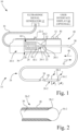
- Ultrasonic transducer 24 is positioned in chamber 20-1 of housing 20, and is connected to carriage 22, such that carriage 22 and ultrasonic transducer 24 are longitudinally movable in unison in chamber 20-1 of housing 20. Stated differently, ultrasonic transducer 24 is configured to longitudinally move in chamber 20-1, relative to housing 20, between a retracted position 44 ( Fig. 1 ) and an extended position 46 ( Fig. 3 ) coincident with a corresponding longitudinal movement of carriage 22. As such, slack is provided in multi-conductor cable 16 within housing 20 to accommodate the movement of carriage 22 and ultrasonic transducer 24. It is noted that retracted position 44 of ultrasonic transducer 24 corresponds with first position 36 of carriage 22, and extended position 46 of ultrasonic transducer 24 corresponds to second position 38 of carriage 22.
- ultrasonic transducer 24 is connected to the proximal end portion 26-1 of the ultrasonic catheter 26, then ultrasonic catheter 26 moves coincident with a longitudinal movement of the ultrasonic transducer 24.
- the combination of carriage 22, ultrasonic transducer 24, and ultrasonic catheter 26 are longitudinally movable relative to housing 20 of handle 18 by a longitudinal displacement of operator arm 22-1 relative to housing 20.
- operator arm 22-1 of carriage 22 may be slidably operated, e.g., by the thumb or forefinger of the user, to move carriage 22 and ultrasonic transducer 24 within chamber 20-1 of housing 20 of ultrasonic probe assembly 14. This movement of carriage 22 and ultrasonic transducer 24 translates into a corresponding movement of engagement end 30-2 of ultrasonic core wire 30 of ultrasonic catheter 26.
- catheter sheath 28 and engagement end 30-2 of ultrasonic core wire 30 of ultrasonic catheter 26 may be moved fore and aft by movement of carriage 22 and ultrasonic transducer 24 while handle 18 of ultrasonic probe assembly 14 is stationary relative to the patient, thereby providing more user control over the advancement and retraction of the engagement end 30-2 of ultrasonic core wire 30 of ultrasonic catheter 26 during a procedure.
- ultrasonic probe assembly 14 further, in whole or in part, includes a control mechanism 48, e.g., a control circuit, that is configured to control the operation of the ultrasonic transducer 24 depending upon a position, e.g., a direction of movement, of carriage 22 and ultrasonic transducer 24 in each of the crossing mode and the atherectomy mode. More particularly, in the crossing mode, control mechanism 48 facilitates operation of ultrasonic transducer 24, and in turn ultrasonic catheter 26, when ultrasonic transducer 24 is moved in either of the proximal direction 40 or the distal direction 42, between the retracted position 44 and the extended position 46. Also, in the atherectomy mode, control mechanism 48 is configured to restrict operation of ultrasonic transducer 24 if movement of ultrasonic transducer 24 (and carriage 22) is attempted in the distal direction 42 toward the extended position 46.
- a control mechanism 48 e.g., a control circuit
- an electrical solution may be, for example, to reduce or cut off electrical power to ultrasonic transducer 24 if movement is attempted in the distal direction 42 while in the atherectomy mode.
- a mechanical solution to restrict operation of ultrasonic transducer 24 in the atherectomy mode may be to provide a mechanical block in housing 20 that only allows one-way movement of carriage 22 and ultrasonic transducer 24 in only the proximal direction 40 while operating in the atherectomy mode.
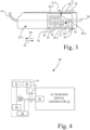
- control mechanism 48 includes a first button 50, a second button 52, a sensor 54, and a control circuit 56.
- First button 50 and second button 52 may be included with, and attached to, housing 20 of ultrasonic probe assembly 14.
- First button 50 and second button 52 may be, for example, a respective pushbutton, a selector switch, a slider switch, or input icons on ultrasonic probe assembly 14.
- first button 50 and second button 52 may be incorporated into a user interface display 60 (see Fig. 1 ) that is separate from, but communicatively coupled to, ultrasonic probe assembly 14.
- First button 50 is actuated by the user to select the crossing mode
- second button 52 is actuated by the user to select the atherectomy mode.
- Ultrasonic signal generator 12 is communicatively coupled to each of first button 50 and second button 52, e.g., via multi-conductor cable 16.
- first button 50 ultrasonic signal generator 12 generates the electrical excitation signal having the first output power, associated with the crossing mode.
- second button 52 ultrasonic signal generator 12 generates the electrical excitation signal having the second output power, associated with the atherectomy mode.
- Sensor 54 is configured to detect a direction of movement of the ultrasonic transducer 24 in the chamber 20-1 of the housing 20.
- Sensor 54 may be, for example, a proximity sensor or a slide rheostat. More particularly, in the present embodiment, sensor 54 is positioned in housing 20 to detect a direction of movement of carriage 22, and in turn, to detect a direction of movement of ultrasonic transducer 24.
- Control circuit 56 is communicatively coupled to sensor 54 and to ultrasonic signal generator 12. Control circuit 56 may be configured to cut off the electrical excitation signal from ultrasonic transducer 24 if the sensor 54 detects movement of the ultrasonic transducer 24 in the distal direction 42 while in the atherectomy mode (second button 52 actuated).
- second button 52 control mechanism 48 depicted in Fig. 4
- a sensor output of sensor 54 and a button output of second button 52 serve as inputs to an AND gate 58, wherein the output of AND gate 58 is connected to control circuit 56, such as a normally closed switch.
- control circuit 56 may be configured as a cutoff switch located in ultrasonic signal generator 12, so as to prohibit operation of ultrasonic signal generator 12 in the atherectomy mode (second button 52 actuated) if sensor 54 detects movement of the ultrasonic transducer 24 in the distal direction 42 in chamber 20-1 of housing 20.
- control circuit 56 may be configured as a cutoff switch located at an electrical input to ultrasonic transducer 24, so as to prohibit operation of ultrasonic transducer 24 in the atherectomy mode (second button 52 actuated) if sensor 54 detects movement of the ultrasonic transducer 24 in the distal direction 42 in chamber 20-1 of housing 20.
- control circuit 56 may be further configured to send a warning, e.g., posting a message on user interface display 60, that the electrical excitation signal has been cut off the from ultrasonic transducer 24 due to a distal advancement of engagement end 30-2 of ultrasonic catheter 26 during the atherectomy mode, and may further provide instructions for corrective action.
- a warning e.g., posting a message on user interface display 60, that the electrical excitation signal has been cut off the from ultrasonic transducer 24 due to a distal advancement of engagement end 30-2 of ultrasonic catheter 26 during the atherectomy mode, and may further provide instructions for corrective action.
- ultrasonic system 10 may include a catheter slider 62 slidably coupled to housing 20.
- Catheter slider 62 is connected to the catheter sheath 28 so as to move catheter sheath 28 relative to ultrasonic core wire 30.
- catheter slider 62 may be positioned such that engagement end 30-2 of the ultrasonic core wire 30 is at a first distance 64 from the distal sheath end 28-2 of the catheter sheath 28 (e.g., fully retracted).
- catheter slider 62 may be positioned such that engagement end 30-2 of the ultrasonic core wire 30 is a second distance 66 from the distal sheath end 28-2 of the catheter sheath 28, e.g., in a fully extended position, so as to expose more of a distal portion of ultrasonic core wire 30.
- the invention relates to an ultrasonic probe assembly for use in an ultrasonic system that may include a handle, a carriage, an ultrasonic catheter, and an ultrasonic transducer.
- the handle is configured to be handheld, and the handle includes a housing that defines a chamber.
- the carriage is slidably coupled to the housing in the chamber.
- the carriage is configured to longitudinally move along the housing between a first position and a second position.
- the carriage has an operator arm that is configured to be operable by a user to move the carriage between the first position and the second position.
- the ultrasonic catheter has a catheter sheath and an ultrasonic core wire.
- the ultrasonic catheter has a proximal end portion and a distal end portion.
- the ultrasonic transducer is positioned in the chamber of the housing.
- the ultrasonic transducer is connected to the proximal end portion of the ultrasonic catheter, and the ultrasonic transducer is connected to the carriage.
- the ultrasonic transducer is configured to longitudinally move in the chamber of the housing between a retracted position and an extended position coincident with a corresponding longitudinal movement of the carriage.
- the ultrasonic catheter is configured to move coincident with a longitudinal movement of the ultrasonic transducer.
- the ultrasonic catheter may be selectively operable in each of a crossing mode and an atherectomy mode.
- such embodiments may further comprise a control mechanism configured such that, in the crossing mode, the control mechanism facilitates operation of the ultrasonic transducer when the ultrasonic transducer is moved in either of a proximal direction or a distal direction between the retracted position and the extended position, and in the atherectomy mode, the control mechanism is configured to restrict operation of the ultrasonic transducer if the ultrasonic transducer is moved in the distal direction toward the extended position.
- the ultrasonic transducer/ultrasonic probe assembly may be configured to supply vibratory energy to the ultrasonic core wire at a first ultrasonic energy level in the crossing mode, and to supply vibratory energy to the ultrasonic core wire at a second ultrasonic energy level, greater than the first ultrasonic energy level, in the atherectomy mode.
- the ultrasonic transducer/ultrasonic probe assembly may be configured such that vibratory energy that is supplied to the ultrasonic core wire at the second ultrasonic energy level may cause both longitudinal and transverse vibrations of the ultrasonic core wire.
- the control mechanism may include a sensor and a control circuit.
- the sensor may be located in the housing of the handle.
- the sensor is configured to detect a direction of movement of the ultrasonic transducer in the chamber of the housing.
- the control circuit is communicatively coupled to the sensor and the ultrasonic signal generator.
- the control circuit is configured to prohibit operation of the ultrasonic catheter in the atherectomy mode if the sensor detects movement of the ultrasonic transducer in the distal direction in the chamber of the housing.
- the senor may be positioned in the housing to detect a direction of movement of the carriage.
- the catheter sheath has a distal sheath end and the ultrasonic core wire has an engagement end, wherein optionally, the engagement end is moveable relative to the distal sheath end.
- the ultrasonic probe assembly may further comprise a catheter slider connected to the catheter sheath.
- the catheter slider may be configured to move the catheter sheath from a home position, wherein the engagement end of the ultrasonic core wire is positioned a first distance from the distal sheath end of the catheter sheath in the crossing mode, and the catheter slider may be configured to position the engagement end of the ultrasonic core wire a second distance from the distal sheath end of the catheter sheath in the atherectomy mode, wherein the second distance is greater than the first distance.
- the ultrasonic transducer may be configured to receive an electrical excitation signal from an ultrasonic signal generator.
- the invention in another form, relates to an ultrasonic system that may include an ultrasonic signal generator and an ultrasonic probe assembly, optionally the ultrasonic probe assembly of any of the preceding paragraphs [0040] to [0049].
- the ultrasonic probe assembly is communicatively coupled to the ultrasonic signal generator.
- the ultrasonic probe assembly may include a handle, a carriage, an ultrasonic catheter, and an ultrasonic transducer.
- the handle is configured to be handheld.
- the handle includes a housing that defines a chamber.
- the carriage is slidably coupled to the housing in the chamber.
- the carriage is configured to longitudinally move along the housing between a first position and a second position.
- the carriage may have an operator arm configured to be operable by a user to move the carriage between the first position and the second position.
- the ultrasonic catheter has a catheter sheath and an ultrasonic core wire.
- the ultrasonic catheter has a proximal end portion and a distal end portion.
- the ultrasonic transducer is positioned in the chamber of the housing.
- the ultrasonic transducer is connected to the proximal end portion of the ultrasonic catheter, and the ultrasonic transducer is connected to the carriage.
- the ultrasonic transducer is configured to longitudinally move in the chamber of the housing between a retracted position and an extended position coincident with a corresponding longitudinal movement of the carriage.
- the ultrasonic system may be configured such that the ultrasonic catheter moves coincident with a longitudinal movement of the ultrasonic transducer.
- the ultrasonic system may be selectively operable in each of a crossing mode and an atherectomy mode.
- the ultrasonic system may further comprise a control mechanism configured such that, in the crossing mode, the control mechanism facilitates operation of the ultrasonic transducer when the ultrasonic transducer is moved in either of a proximal direction or a distal direction between the retracted position and the extended position, and in the atherectomy mode, the control mechanism is configured to restrict operation of the ultrasonic transducer if the ultrasonic transducer is moved in the distal direction toward the extended position.
- the ultrasonic system may be configured such that, in the crossing mode, the ultrasonic transducer supplies vibratory energy to the ultrasonic core wire at a first ultrasonic energy level, and in the atherectomy mode, the ultrasonic transducer supplies vibratory energy to the ultrasonic core wire at a second ultrasonic energy level greater than the first ultrasonic energy level.
- the handle may include a first button for selecting the crossing mode, and a second button for selecting the atherectomy mode.
- the ultrasonic signal generator may be communicatively coupled to each of the first button and the second button.
- the ultrasonic signal generator may be configured to generate an electrical excitation signal that has a first output power when the crossing mode is selected by actuation of the first button, and the electrical excitation signal has a second output power, greater than the first output power, when the atherectomy mode is selected by actuation of the second button.
- the ultrasonic signal generator is electrically connected to the ultrasonic transducer.
- the ultrasonic signal generator is configured to selectively supply the electrical excitation signal to the ultrasonic transducer.
- the control mechanism may include a sensor and a control circuit.
- the sensor may be located in the housing of the handle, wherein the sensor is configured to detect a direction of movement of the ultrasonic transducer in the chamber of the housing.
- the control circuit is communicatively coupled to the sensor and the ultrasonic signal generator.
- the control circuit is configured to prohibit operation of the ultrasonic signal generator in the atherectomy mode if the sensor detects movement of the ultrasonic transducer in the distal direction in the chamber of the housing.
- control circuit may be optionally configured to cut off the electrical excitation signal from the ultrasonic transducer if the sensor detects movement of the ultrasonic transducer in the distal direction.
- the senor may be positioned in the housing to detect a direction of movement of the carriage.
- the catheter sheath may have a distal sheath end and the ultrasonic core wire may have an engagement end.
- the ultrasonic system may further comprise a catheter slider connected to the catheter sheath, wherein the catheter slider is configured to position the engagement end of the ultrasonic core wire a first distance from the distal sheath end of the catheter sheath in the crossing mode, and the catheter slider is configured to position the engagement end of the ultrasonic core wire a second distance from the distal sheath end of the catheter sheath in the atherectomy mode, wherein the second distance is greater than the first distance.
- the term "substantially”, and any other word of degree, is a relative modifier intended to indicate permissible variation from the characteristic so modified. Such terms are not intended to be limited to the absolute value of the characteristic which it modifies, but rather possessing more of the physical or functional characteristic than the opposite, and approaching or approximating such a physical or functional characteristic.
Landscapes
- Health & Medical Sciences (AREA)
- Surgery (AREA)
- Life Sciences & Earth Sciences (AREA)
- Engineering & Computer Science (AREA)
- Heart & Thoracic Surgery (AREA)
- Veterinary Medicine (AREA)
- Nuclear Medicine, Radiotherapy & Molecular Imaging (AREA)
- Biomedical Technology (AREA)
- Public Health (AREA)
- Medical Informatics (AREA)
- Molecular Biology (AREA)
- Animal Behavior & Ethology (AREA)
- General Health & Medical Sciences (AREA)
- Mechanical Engineering (AREA)
- Orthopedic Medicine & Surgery (AREA)
- Vascular Medicine (AREA)
- Dentistry (AREA)
- Surgical Instruments (AREA)
Claims (15)
- Ultraschallsondenanordnung (14) zur Verwendung in einem Ultraschallsystem (10), umfassend:einen Griff (18), der konfiguriert ist, um in der Hand gehalten zu werden, wobei der Griff ein Gehäuse (20) einschließt, das eine Kammer (20-1) definiert;einen Schlitten (22), der verschiebbar mit dem Gehäuse in der Kammer gekoppelt ist, wobei der Schlitten konfiguriert ist, um sich longitudinal entlang des Gehäuses zwischen einer ersten Position und einer zweiten Position zu bewegen, wobei der Schlitten einen Bedienerarm (22-1) aufweist, der konfiguriert ist, um von einem Benutzer bedient zu werden, um den Schlitten zwischen der ersten Position und der zweiten Position zu bewegen;einen Ultraschallkatheter (26), der eine Katheterhülle (28) und einen Ultraschallkerndraht (30) aufweist, wobei der Ultraschallkatheter einen proximalen Endabschnitt (26-1) und einen distalen Endabschnitt (26-2) aufweist;einen Ultraschallwandler (24), der in der Kammer des Gehäuses positioniert ist, wobei der Ultraschallwandler mit dem proximalen Endabschnitt des Ultraschallkatheters verbunden ist und der Ultraschallwandler mit dem Schlitten verbunden ist, wobei der Ultraschallwandler konfiguriert ist, um sich in der Kammer des Gehäuses longitudinal zwischen einer eingefahrenen Position (44) und einer ausgefahrenen Position (46) übereinstimmend mit einer entsprechenden longitudinalen Bewegung des Schlittens zu bewegen, und wobei sich der Ultraschallkatheter übereinstimmend mit einer longitudinalen Bewegung des Ultraschallwandlers bewegt.
- Ultraschallsondenanordnung nach Anspruch 1, wobei der Ultraschallkatheter selektiv in jedem aus einem Kreuzungsmodus und einem Atherektomiemodus betrieben werden kann, und weiter einen Steuermechanismus (48) umfasst, der konfiguriert ist, sodass im Kreuzungsmodus der Steuermechanismus den Betrieb des Ultraschallwandlers erleichtert, wenn der Ultraschallwandler entweder in einer proximalen Richtung oder einer distalen Richtung zwischen der eingefahrenen Position und der ausgefahrenen Position bewegt wird, und im Atherektomiemodus der Steuermechanismus konfiguriert ist, um den Betrieb des Ultraschallwandlers einzuschränken, falls der Ultraschallwandler in der distalen Richtung in Richtung der ausgefahrenen Position bewegt wird.
- Ultraschallsondenanordnung nach Anspruch 2, wobei der Ultraschallwandler konfiguriert ist, um dem Ultraschallkerndraht im Kreuzungsmodus Schwingungsenergie mit einem ersten Ultraschallenergieniveau zuzuführen und dem Ultraschallkerndraht im Atherektomiemodus Schwingungsenergie mit einem zweiten Ultraschallenergieniveau zuzuführen, das größer ist als das erste Ultraschallenergieniveau.
- Ultraschallsondenanordnung nach Anspruch 3, wobei die dem Ultraschallkerndraht mit dem zweiten Ultraschallenergieniveau zugeführte Schwingungsenergie sowohl longitudinale als auch transversale Schwingungen des Ultraschallkerndrahtes verursacht.
- Ultraschallsondenanordnung nach einem der Ansprüche 2 bis 4, wobei der Steuermechanismus Folgendes umfasst:einen Sensor (54), der in dem Gehäuse des Griffs gelegen ist, wobei der Sensor konfiguriert ist, um eine Richtung einer Bewegung des Ultraschallwandlers in der Kammer des Gehäuses zu erfassen; undeine Steuerschaltung (56), die kommunikativ mit dem Sensor und dem Ultraschallsignalgenerator gekoppelt ist, wobei die Steuerschaltung konfiguriert ist, um den Betrieb des Ultraschallkatheters im Atherektomiemodus zu unterbinden, falls der Sensor eine Bewegung des Ultraschallwandlers in der distalen Richtung in der Kammer des Gehäuses erfasst.
- Ultraschallsondenanordnung nach Anspruch 5, wobei der Sensor (54) im Gehäuse positioniert ist, um eine Richtung einer Bewegung des Schlittens zu erfassen.
- Ultraschallsondenanordnung nach einem der Ansprüche 1 bis 6, wobei die Katheterhülle ein distales Hüllenende (28-2) aufweist und der Ultraschallkerndraht ein Eingriffsende (30-2) aufweist, wobei das Eingriffsende relativ zum distalen Hüllenende beweglich ist.
- Ultraschallsondenanordnung nach Anspruch 7, wobei die Ultraschallsondenanordnung weiter einen Katheterschieber (62) umfasst, der mit der Katheterhülle verbunden ist, wobei der Katheterschieber konfiguriert ist, um die Katheterhülle (28) aus einer Ausgangsposition zu bewegen, in der das Eingriffsende des Ultraschallkerndrahtes (30) in einem ersten Abstand vom distalen Hüllenende der Katheterhülle im Kreuzungsmodus positioniert ist, und der Katheterschieber konfiguriert ist, um das Eingriffsende des Ultraschallkerndrahtes in einem zweiten Abstand vom distalen Hüllenende der Katheterhülle im Atherektomiemodus zu positionieren, wobei der zweite Abstand größer ist als der erste Abstand.
- Ultraschallsondenanordnung nach einem der Ansprüche 1 - 8, wobei der Ultraschallwandler konfiguriert ist, um ein elektrisches Erregungssignal von einem Ultraschallsignalgenerator (12) zu empfangen.
- Ultraschallsystem, umfassend:einen Ultraschallsignalgenerator (12); unddie Ultraschallsondenanordnung nach Anspruch 1.
- Ultraschallsystem nach Anspruch 10, wobei das System selektiv in jedem aus einem Kreuzungsmodus und einem Atherektomiemodus betrieben werden kann, und weiter umfassend einen Steuermechanismus (48), der konfiguriert ist, sodass im Kreuzungsmodus der Steuermechanismus den Betrieb des Ultraschallwandlers erleichtert, wenn der Ultraschallwandler entweder in einer proximalen Richtung oder einer distalen Richtung zwischen der eingefahrenen Position und der ausgefahrenen Position bewegt wird, und im Atherektomiemodus der Steuermechanismus konfiguriert ist, um den Betrieb des Ultraschallwandlers einzuschränken, falls der Ultraschallwandler in der distalen Richtung in Richtung der ausgefahrenen Position bewegt wird.
- Ultraschallsystem nach Anspruch 11, wobei der Ultraschallwandler dem Ultraschallkerndraht im Kreuzungsmodus Schwingungsenergie mit einem ersten Ultraschallenergieniveau zuführt und der Ultraschallwandler dem Ultraschallkerndraht im Atherektomiemodus Schwingungsenergie mit einem zweiten Ultraschallenergieniveau zuführt, das größer ist als das erste Ultraschallenergieniveau.
- Ultraschallsystem nach einem der Ansprüche 11 oder 12, wobei:der Griff eine erste Taste (50) zum Auswählen des Kreuzungsmodus und eine zweite Taste (52) zum Auswählen des Atherektomiemodus einschließt;der Ultraschallsignalgenerator (12) kommunikativ mit jeder der ersten Taste und der zweiten Taste gekoppelt ist, der Ultraschallsignalgenerator konfiguriert ist, um ein elektrisches Erregungssignal, das eine erste Ausgangsleistung aufweist, zu erzeugen, wenn der Kreuzungsmodus durch Betätigung der ersten Taste (50) ausgewählt wird, und das elektrische Erregungssignal eine zweite Ausgangsleistung aufweist, die größer ist als die erste Ausgangsleistung, wenn der Atherektomiemodus durch Betätigung der zweiten Taste (52) ausgewählt wird, wobei der Ultraschallsignalgenerator elektrisch mit dem Ultraschallwandler verbunden ist, wobei der Ultraschallsignalgenerator konfiguriert ist, um das elektrische Erregungssignal selektiv dem Ultraschallwandler zuzuführen; undder Steuermechanismus (48) Folgendes einschließt:einen Sensor (54), der in dem Gehäuse des Griffs gelegen ist, wobei der Sensor konfiguriert ist, um eine Richtung einer Bewegung des Ultraschallwandlers in der Kammer des Gehäuses zu erfassen; undeine Steuerschaltung (56), die kommunikativ mit dem Sensor und dem Ultraschallsignalgenerator gekoppelt ist, wobei die Steuerschaltung konfiguriert ist, um den Betrieb des Ultraschallsignalgenerators im Atherektomiemodus zu unterbinden, falls der Sensor eine Bewegung des Ultraschallwandlers in der distalen Richtung in der Kammer des Gehäuses erfasst.
- Ultraschallsystem nach Anspruch 13, wobei die Steuerschaltung (56) konfiguriert ist, um das elektrische Erregungssignal des Ultraschallwandlers zu unterbrechen, falls der Sensor eine Bewegung des Ultraschallwandlers in die distale Richtung erfasst; und optional wobei der Sensor im Gehäuse positioniert ist, um eine Richtung einer Bewegung des Schlittens zu erfassen.
- Ultraschallsystem nach einem der Ansprüche 10 bis 14, wobei die Katheterhülle ein distales Hüllenende aufweist und der Ultraschallkerndraht ein Eingriffsende aufweist, wobei das Ultraschallsystem weiter einen Katheterschieber umfasst, der mit der Katheterhülle verbunden ist, wobei der Katheterschieber konfiguriert ist, um das Eingriffsende des Ultraschallkerndrahtes in einem ersten Abstand vom distalen Hüllenende der Katheterhülle im Kreuzungsmodus zu positionieren, und der Katheterschieber konfiguriert ist, um das Eingriffsende des Ultraschallkerndrahtes in einem zweiten Abstand vom distalen Hüllenende der Katheterhülle im Atherektomiemodus zu positionieren, wobei der zweite Abstand größer ist als der erste Abstand.
Applications Claiming Priority (1)
| Application Number | Priority Date | Filing Date | Title |
|---|---|---|---|
| PCT/US2019/063254 WO2021107927A1 (en) | 2019-11-26 | 2019-11-26 | Ultrasonic probe assembly and system |
Publications (3)
| Publication Number | Publication Date |
|---|---|
| EP4065010A1 EP4065010A1 (de) | 2022-10-05 |
| EP4065010B1 true EP4065010B1 (de) | 2024-04-24 |
| EP4065010C0 EP4065010C0 (de) | 2024-04-24 |
Family
ID=68916624
Family Applications (1)
| Application Number | Title | Priority Date | Filing Date |
|---|---|---|---|
| EP19821414.0A Active EP4065010B1 (de) | 2019-11-26 | 2019-11-26 | Ultraschallsondenanordnung und system |
Country Status (5)
| Country | Link |
|---|---|
| US (1) | US20220387054A1 (de) |
| EP (1) | EP4065010B1 (de) |
| JP (1) | JP7444982B2 (de) |
| CN (1) | CN114746031A (de) |
| WO (1) | WO2021107927A1 (de) |
Families Citing this family (2)
| Publication number | Priority date | Publication date | Assignee | Title |
|---|---|---|---|---|
| US20250114112A1 (en) * | 2022-02-15 | 2025-04-10 | Bard Peripheral Vascular, Inc. | Occlusion crossing catheters and methods for using the same |
| WO2025213145A1 (en) * | 2024-04-05 | 2025-10-09 | Method Ai, Inc. | Surgical navigation system |
Family Cites Families (17)
| Publication number | Priority date | Publication date | Assignee | Title |
|---|---|---|---|---|
| JPH0621450Y2 (ja) * | 1990-07-05 | 1994-06-08 | アロカ株式会社 | 超音波手術器 |
| US5383460A (en) * | 1992-10-05 | 1995-01-24 | Cardiovascular Imaging Systems, Inc. | Method and apparatus for ultrasound imaging and atherectomy |
| US5989274A (en) * | 1996-10-17 | 1999-11-23 | Ethicon Endo-Surgery, Inc. | Methods and devices for improving blood flow to a heart of a patient |
| US7220233B2 (en) * | 2003-04-08 | 2007-05-22 | Flowcardia, Inc. | Ultrasound catheter devices and methods |
| US20040210140A1 (en) * | 2003-04-15 | 2004-10-21 | Omnisonics Medical Technologies, Inc. | Apparatus and method for preshaped ultrasonic probe |
| US7794414B2 (en) * | 2004-02-09 | 2010-09-14 | Emigrant Bank, N.A. | Apparatus and method for an ultrasonic medical device operating in torsional and transverse modes |
| US20090264770A1 (en) * | 2008-04-17 | 2009-10-22 | Omnisonics Medical Technologies, Inc. | Medical Systems and Related Methods |
| US9114245B2 (en) * | 2009-08-14 | 2015-08-25 | Ethicon Endo-Surgery, Inc. | Ultrasonic surgical apparatus and methods for use thereof |
| US20110105960A1 (en) * | 2009-10-06 | 2011-05-05 | Wallace Michael P | Ultrasound-enhanced Stenosis therapy |
| US10596033B2 (en) * | 2012-03-26 | 2020-03-24 | Alex Urich | Phacoemulsification ultrasonic device switching between different operational modes |
| US20140081299A1 (en) * | 2012-09-19 | 2014-03-20 | Timothy G. Dietz | Micromachined Ultrasonic Scalpel with Embedded Piezoelectric Actuator |
| KR101307551B1 (ko) * | 2013-03-26 | 2013-09-12 | (주)클래시스 | 초음파 장치의 핸드피스 |
| WO2016081026A1 (en) * | 2014-11-19 | 2016-05-26 | C.R. Bard, Inc. | Ultrasound catheter and system with multiple function modes |
| JP2018500075A (ja) * | 2014-11-26 | 2018-01-11 | アティーブ ビューティー カンパニー リミテッドATTIBE Beauty CO. LTD. | 超音波生成装置及びこれを利用した施術方法 |
| US10357262B2 (en) * | 2016-11-14 | 2019-07-23 | C. R. Bard, Inc. | Systems and methods to modify intravascular lesions |
| US20180140321A1 (en) | 2016-11-23 | 2018-05-24 | C. R. Bard, Inc. | Catheter With Retractable Sheath And Methods Thereof |
| US20190159792A1 (en) * | 2017-11-27 | 2019-05-30 | Justin Panian | Ultrasound Vessel Preparation and Restenosis Therapy |
-
2019
- 2019-11-26 JP JP2022530774A patent/JP7444982B2/ja active Active
- 2019-11-26 US US17/778,278 patent/US20220387054A1/en active Pending
- 2019-11-26 EP EP19821414.0A patent/EP4065010B1/de active Active
- 2019-11-26 CN CN201980102562.8A patent/CN114746031A/zh active Pending
- 2019-11-26 WO PCT/US2019/063254 patent/WO2021107927A1/en not_active Ceased
Also Published As
| Publication number | Publication date |
|---|---|
| EP4065010A1 (de) | 2022-10-05 |
| CN114746031A (zh) | 2022-07-12 |
| US20220387054A1 (en) | 2022-12-08 |
| JP2023510686A (ja) | 2023-03-15 |
| JP7444982B2 (ja) | 2024-03-06 |
| EP4065010C0 (de) | 2024-04-24 |
| WO2021107927A1 (en) | 2021-06-03 |
Similar Documents
| Publication | Publication Date | Title |
|---|---|---|
| US10918406B2 (en) | Surgical apparatus with jaw force limiter | |
| KR101619583B1 (ko) | 혈관 융합 및 분리용 기기 | |
| EP4065010B1 (de) | Ultraschallsondenanordnung und system | |
| CN100358480C (zh) | 用于内诊镜或导液管的电手术器械 | |
| EP2214772B1 (de) | Hf-ablationsvorrichtung mit stau-verhinderndem elektrischem kopplungselement | |
| JP2011502721A (ja) | 組織の塊を破壊するための固定型高周波切断装置 | |
| JP2004358240A (ja) | 尿管切除鏡 | |
| US20190365408A1 (en) | Catheter with retractable sheath and methods thereof | |
| JPWO2014156221A1 (ja) | 医療器具及び医療システム | |
| WO2016081026A1 (en) | Ultrasound catheter and system with multiple function modes | |
| AU2017433175B2 (en) | Apparatus and method for tracking a medical ultrasonic object | |
| EP3389531B1 (de) | Elektrochirurgische vorrichtung | |
| JP5098024B2 (ja) | 内視鏡用高周波処置具 | |
| EP1847231B1 (de) | Elastische bipolare Zange | |
| CN215688371U (zh) | 一种高频粘膜切开刀 | |
| JP2010035695A (ja) | 内視鏡用処置具 | |
| CN104856753A (zh) | 手术设备 | |
| JP4320194B2 (ja) | 内視鏡用高周波メス | |
| US20250114112A1 (en) | Occlusion crossing catheters and methods for using the same | |
| US20180280078A1 (en) | Electrical surgical system for cutting or cauterizing tissue and a method of the same | |
| JP4495442B2 (ja) | 内視鏡用高周波処置具 | |
| JP5191365B2 (ja) | 内視鏡用高周波処置具 | |
| JPH05211994A (ja) | 内視鏡用処置具 | |
| CN120815272A (zh) | 导丝自动推送系统 | |
| JP2000333969A (ja) | 電気手術装置 |
Legal Events
| Date | Code | Title | Description |
|---|---|---|---|
| STAA | Information on the status of an ep patent application or granted ep patent |
Free format text: STATUS: UNKNOWN |
|
| STAA | Information on the status of an ep patent application or granted ep patent |
Free format text: STATUS: THE INTERNATIONAL PUBLICATION HAS BEEN MADE |
|
| PUAI | Public reference made under article 153(3) epc to a published international application that has entered the european phase |
Free format text: ORIGINAL CODE: 0009012 |
|
| STAA | Information on the status of an ep patent application or granted ep patent |
Free format text: STATUS: REQUEST FOR EXAMINATION WAS MADE |
|
| 17P | Request for examination filed |
Effective date: 20220621 |
|
| AK | Designated contracting states |
Kind code of ref document: A1 Designated state(s): AL AT BE BG CH CY CZ DE DK EE ES FI FR GB GR HR HU IE IS IT LI LT LU LV MC MK MT NL NO PL PT RO RS SE SI SK SM TR |
|
| DAV | Request for validation of the european patent (deleted) | ||
| DAX | Request for extension of the european patent (deleted) | ||
| GRAP | Despatch of communication of intention to grant a patent |
Free format text: ORIGINAL CODE: EPIDOSNIGR1 |
|
| STAA | Information on the status of an ep patent application or granted ep patent |
Free format text: STATUS: GRANT OF PATENT IS INTENDED |
|
| INTG | Intention to grant announced |
Effective date: 20231213 |
|
| RAP3 | Party data changed (applicant data changed or rights of an application transferred) |
Owner name: BARD PERIPHERAL VASCULAR, INC. |
|
| GRAS | Grant fee paid |
Free format text: ORIGINAL CODE: EPIDOSNIGR3 |
|
| GRAA | (expected) grant |
Free format text: ORIGINAL CODE: 0009210 |
|
| STAA | Information on the status of an ep patent application or granted ep patent |
Free format text: STATUS: THE PATENT HAS BEEN GRANTED |
|
| AK | Designated contracting states |
Kind code of ref document: B1 Designated state(s): AL AT BE BG CH CY CZ DE DK EE ES FI FR GB GR HR HU IE IS IT LI LT LU LV MC MK MT NL NO PL PT RO RS SE SI SK SM TR |
|
| REG | Reference to a national code |
Ref country code: GB Ref legal event code: FG4D |
|
| REG | Reference to a national code |
Ref country code: CH Ref legal event code: EP |
|
| REG | Reference to a national code |
Ref country code: DE Ref legal event code: R096 Ref document number: 602019051019 Country of ref document: DE |
|
| REG | Reference to a national code |
Ref country code: IE Ref legal event code: FG4D |
|
| U01 | Request for unitary effect filed |
Effective date: 20240424 |
|
| U07 | Unitary effect registered |
Designated state(s): AT BE BG DE DK EE FI FR IT LT LU LV MT NL PT SE SI Effective date: 20240430 |
|
| PG25 | Lapsed in a contracting state [announced via postgrant information from national office to epo] |
Ref country code: IS Free format text: LAPSE BECAUSE OF FAILURE TO SUBMIT A TRANSLATION OF THE DESCRIPTION OR TO PAY THE FEE WITHIN THE PRESCRIBED TIME-LIMIT Effective date: 20240824 |
|
| PG25 | Lapsed in a contracting state [announced via postgrant information from national office to epo] |
Ref country code: HR Free format text: LAPSE BECAUSE OF FAILURE TO SUBMIT A TRANSLATION OF THE DESCRIPTION OR TO PAY THE FEE WITHIN THE PRESCRIBED TIME-LIMIT Effective date: 20240424 |
|
| PG25 | Lapsed in a contracting state [announced via postgrant information from national office to epo] |
Ref country code: GR Free format text: LAPSE BECAUSE OF FAILURE TO SUBMIT A TRANSLATION OF THE DESCRIPTION OR TO PAY THE FEE WITHIN THE PRESCRIBED TIME-LIMIT Effective date: 20240725 |
|
| PG25 | Lapsed in a contracting state [announced via postgrant information from national office to epo] |
Ref country code: ES Free format text: LAPSE BECAUSE OF FAILURE TO SUBMIT A TRANSLATION OF THE DESCRIPTION OR TO PAY THE FEE WITHIN THE PRESCRIBED TIME-LIMIT Effective date: 20240424 |
|
| PG25 | Lapsed in a contracting state [announced via postgrant information from national office to epo] |
Ref country code: PL Free format text: LAPSE BECAUSE OF FAILURE TO SUBMIT A TRANSLATION OF THE DESCRIPTION OR TO PAY THE FEE WITHIN THE PRESCRIBED TIME-LIMIT Effective date: 20240424 |
|
| PG25 | Lapsed in a contracting state [announced via postgrant information from national office to epo] |
Ref country code: PL Free format text: LAPSE BECAUSE OF FAILURE TO SUBMIT A TRANSLATION OF THE DESCRIPTION OR TO PAY THE FEE WITHIN THE PRESCRIBED TIME-LIMIT Effective date: 20240424 Ref country code: NO Free format text: LAPSE BECAUSE OF FAILURE TO SUBMIT A TRANSLATION OF THE DESCRIPTION OR TO PAY THE FEE WITHIN THE PRESCRIBED TIME-LIMIT Effective date: 20240724 Ref country code: IS Free format text: LAPSE BECAUSE OF FAILURE TO SUBMIT A TRANSLATION OF THE DESCRIPTION OR TO PAY THE FEE WITHIN THE PRESCRIBED TIME-LIMIT Effective date: 20240824 Ref country code: HR Free format text: LAPSE BECAUSE OF FAILURE TO SUBMIT A TRANSLATION OF THE DESCRIPTION OR TO PAY THE FEE WITHIN THE PRESCRIBED TIME-LIMIT Effective date: 20240424 Ref country code: GR Free format text: LAPSE BECAUSE OF FAILURE TO SUBMIT A TRANSLATION OF THE DESCRIPTION OR TO PAY THE FEE WITHIN THE PRESCRIBED TIME-LIMIT Effective date: 20240725 Ref country code: ES Free format text: LAPSE BECAUSE OF FAILURE TO SUBMIT A TRANSLATION OF THE DESCRIPTION OR TO PAY THE FEE WITHIN THE PRESCRIBED TIME-LIMIT Effective date: 20240424 Ref country code: RS Free format text: LAPSE BECAUSE OF FAILURE TO SUBMIT A TRANSLATION OF THE DESCRIPTION OR TO PAY THE FEE WITHIN THE PRESCRIBED TIME-LIMIT Effective date: 20240724 |
|
| U20 | Renewal fee for the european patent with unitary effect paid |
Year of fee payment: 6 Effective date: 20241022 |
|
| PG25 | Lapsed in a contracting state [announced via postgrant information from national office to epo] |
Ref country code: CZ Free format text: LAPSE BECAUSE OF FAILURE TO SUBMIT A TRANSLATION OF THE DESCRIPTION OR TO PAY THE FEE WITHIN THE PRESCRIBED TIME-LIMIT Effective date: 20240424 |
|
| PG25 | Lapsed in a contracting state [announced via postgrant information from national office to epo] |
Ref country code: RO Free format text: LAPSE BECAUSE OF FAILURE TO SUBMIT A TRANSLATION OF THE DESCRIPTION OR TO PAY THE FEE WITHIN THE PRESCRIBED TIME-LIMIT Effective date: 20240424 Ref country code: SK Free format text: LAPSE BECAUSE OF FAILURE TO SUBMIT A TRANSLATION OF THE DESCRIPTION OR TO PAY THE FEE WITHIN THE PRESCRIBED TIME-LIMIT Effective date: 20240424 |
|
| REG | Reference to a national code |
Ref country code: DE Ref legal event code: R097 Ref document number: 602019051019 Country of ref document: DE |
|
| PG25 | Lapsed in a contracting state [announced via postgrant information from national office to epo] |
Ref country code: SM Free format text: LAPSE BECAUSE OF FAILURE TO SUBMIT A TRANSLATION OF THE DESCRIPTION OR TO PAY THE FEE WITHIN THE PRESCRIBED TIME-LIMIT Effective date: 20240424 |
|
| PG25 | Lapsed in a contracting state [announced via postgrant information from national office to epo] |
Ref country code: SM Free format text: LAPSE BECAUSE OF FAILURE TO SUBMIT A TRANSLATION OF THE DESCRIPTION OR TO PAY THE FEE WITHIN THE PRESCRIBED TIME-LIMIT Effective date: 20240424 Ref country code: SK Free format text: LAPSE BECAUSE OF FAILURE TO SUBMIT A TRANSLATION OF THE DESCRIPTION OR TO PAY THE FEE WITHIN THE PRESCRIBED TIME-LIMIT Effective date: 20240424 Ref country code: RO Free format text: LAPSE BECAUSE OF FAILURE TO SUBMIT A TRANSLATION OF THE DESCRIPTION OR TO PAY THE FEE WITHIN THE PRESCRIBED TIME-LIMIT Effective date: 20240424 Ref country code: CZ Free format text: LAPSE BECAUSE OF FAILURE TO SUBMIT A TRANSLATION OF THE DESCRIPTION OR TO PAY THE FEE WITHIN THE PRESCRIBED TIME-LIMIT Effective date: 20240424 |
|
| PLBE | No opposition filed within time limit |
Free format text: ORIGINAL CODE: 0009261 |
|
| STAA | Information on the status of an ep patent application or granted ep patent |
Free format text: STATUS: NO OPPOSITION FILED WITHIN TIME LIMIT |
|
| 26N | No opposition filed |
Effective date: 20250127 |
|
| REG | Reference to a national code |
Ref country code: CH Ref legal event code: PL |
|
| PG25 | Lapsed in a contracting state [announced via postgrant information from national office to epo] |
Ref country code: MC Free format text: LAPSE BECAUSE OF FAILURE TO SUBMIT A TRANSLATION OF THE DESCRIPTION OR TO PAY THE FEE WITHIN THE PRESCRIBED TIME-LIMIT Effective date: 20240424 |
|
| REG | Reference to a national code |
Ref country code: CH Ref legal event code: PL |
|
| GBPC | Gb: european patent ceased through non-payment of renewal fee |
Effective date: 20241126 |
|
| PG25 | Lapsed in a contracting state [announced via postgrant information from national office to epo] |
Ref country code: CH Free format text: LAPSE BECAUSE OF NON-PAYMENT OF DUE FEES Effective date: 20241130 |
|
| PG25 | Lapsed in a contracting state [announced via postgrant information from national office to epo] |
Ref country code: GB Free format text: LAPSE BECAUSE OF NON-PAYMENT OF DUE FEES Effective date: 20241126 |
|
| PG25 | Lapsed in a contracting state [announced via postgrant information from national office to epo] |
Ref country code: IE Free format text: LAPSE BECAUSE OF NON-PAYMENT OF DUE FEES Effective date: 20241126 |
|
| U20 | Renewal fee for the european patent with unitary effect paid |
Year of fee payment: 7 Effective date: 20251022 |