EP4064534A1 - Magnetic shaft coupling and use and adjustment method thereof - Google Patents
Magnetic shaft coupling and use and adjustment method thereof Download PDFInfo
- Publication number
- EP4064534A1 EP4064534A1 EP20889997.1A EP20889997A EP4064534A1 EP 4064534 A1 EP4064534 A1 EP 4064534A1 EP 20889997 A EP20889997 A EP 20889997A EP 4064534 A1 EP4064534 A1 EP 4064534A1
- Authority
- EP
- European Patent Office
- Prior art keywords
- magnets
- rotor
- external
- magnetic coupling
- slip rings
- Prior art date
- Legal status (The legal status is an assumption and is not a legal conclusion. Google has not performed a legal analysis and makes no representation as to the accuracy of the status listed.)
- Pending
Links
- 230000008878 coupling Effects 0.000 title claims abstract description 83
- 238000010168 coupling process Methods 0.000 title claims abstract description 83
- 238000005859 coupling reaction Methods 0.000 title claims abstract description 83
- 238000000034 method Methods 0.000 title claims description 9
- 238000013016 damping Methods 0.000 claims abstract description 11
- 238000004804 winding Methods 0.000 claims description 22
- 230000002093 peripheral effect Effects 0.000 claims description 3
- 238000003825 pressing Methods 0.000 claims description 3
- 230000000694 effects Effects 0.000 abstract description 14
- 238000009434 installation Methods 0.000 abstract description 11
- 230000001965 increasing effect Effects 0.000 description 11
- 230000008859 change Effects 0.000 description 6
- 230000002708 enhancing effect Effects 0.000 description 6
- 238000010586 diagram Methods 0.000 description 5
- 238000007789 sealing Methods 0.000 description 4
- 230000003068 static effect Effects 0.000 description 4
- 230000033001 locomotion Effects 0.000 description 3
- 230000005389 magnetism Effects 0.000 description 3
- 230000005540 biological transmission Effects 0.000 description 2
- 238000009826 distribution Methods 0.000 description 2
- 230000005672 electromagnetic field Effects 0.000 description 2
- 230000008569 process Effects 0.000 description 2
- 229910001209 Low-carbon steel Inorganic materials 0.000 description 1
- 230000009471 action Effects 0.000 description 1
- 230000009286 beneficial effect Effects 0.000 description 1
- 230000015572 biosynthetic process Effects 0.000 description 1
- 230000001680 brushing effect Effects 0.000 description 1
- 230000007547 defect Effects 0.000 description 1
- 239000007789 gas Substances 0.000 description 1
- 238000011900 installation process Methods 0.000 description 1
- 239000007788 liquid Substances 0.000 description 1
- 230000005415 magnetization Effects 0.000 description 1
- 238000004519 manufacturing process Methods 0.000 description 1
- 239000000463 material Substances 0.000 description 1
- 230000007246 mechanism Effects 0.000 description 1
- 230000008719 thickening Effects 0.000 description 1
- 239000002699 waste material Substances 0.000 description 1
Images



Classifications
-
- H—ELECTRICITY
- H01—ELECTRIC ELEMENTS
- H01F—MAGNETS; INDUCTANCES; TRANSFORMERS; SELECTION OF MATERIALS FOR THEIR MAGNETIC PROPERTIES
- H01F7/00—Magnets
- H01F7/06—Electromagnets; Actuators including electromagnets
- H01F7/066—Electromagnets with movable winding
-
- H—ELECTRICITY
- H01—ELECTRIC ELEMENTS
- H01F—MAGNETS; INDUCTANCES; TRANSFORMERS; SELECTION OF MATERIALS FOR THEIR MAGNETIC PROPERTIES
- H01F7/00—Magnets
- H01F7/06—Electromagnets; Actuators including electromagnets
- H01F7/20—Electromagnets; Actuators including electromagnets without armatures
-
- H—ELECTRICITY
- H01—ELECTRIC ELEMENTS
- H01R—ELECTRICALLY-CONDUCTIVE CONNECTIONS; STRUCTURAL ASSOCIATIONS OF A PLURALITY OF MUTUALLY-INSULATED ELECTRICAL CONNECTING ELEMENTS; COUPLING DEVICES; CURRENT COLLECTORS
- H01R39/00—Rotary current collectors, distributors or interrupters
- H01R39/64—Devices for uninterrupted current collection
-
- H—ELECTRICITY
- H02—GENERATION; CONVERSION OR DISTRIBUTION OF ELECTRIC POWER
- H02K—DYNAMO-ELECTRIC MACHINES
- H02K13/00—Structural associations of current collectors with motors or generators, e.g. brush mounting plates or connections to windings; Disposition of current collectors in motors or generators; Arrangements for improving commutation
-
- H—ELECTRICITY
- H02—GENERATION; CONVERSION OR DISTRIBUTION OF ELECTRIC POWER
- H02K—DYNAMO-ELECTRIC MACHINES
- H02K21/00—Synchronous motors having permanent magnets; Synchronous generators having permanent magnets
- H02K21/02—Details
- H02K21/04—Windings on magnets for additional excitation ; Windings and magnets for additional excitation
- H02K21/042—Windings on magnets for additional excitation ; Windings and magnets for additional excitation with permanent magnets and field winding both rotating
-
- H—ELECTRICITY
- H02—GENERATION; CONVERSION OR DISTRIBUTION OF ELECTRIC POWER
- H02K—DYNAMO-ELECTRIC MACHINES
- H02K49/00—Dynamo-electric clutches; Dynamo-electric brakes
- H02K49/06—Dynamo-electric clutches; Dynamo-electric brakes of the synchronous type
-
- H—ELECTRICITY
- H02—GENERATION; CONVERSION OR DISTRIBUTION OF ELECTRIC POWER
- H02K—DYNAMO-ELECTRIC MACHINES
- H02K49/00—Dynamo-electric clutches; Dynamo-electric brakes
- H02K49/10—Dynamo-electric clutches; Dynamo-electric brakes of the permanent-magnet type
- H02K49/104—Magnetic couplings consisting of only two coaxial rotary elements, i.e. the driving element and the driven element
- H02K49/106—Magnetic couplings consisting of only two coaxial rotary elements, i.e. the driving element and the driven element with a radial air gap
-
- H—ELECTRICITY
- H02—GENERATION; CONVERSION OR DISTRIBUTION OF ELECTRIC POWER
- H02K—DYNAMO-ELECTRIC MACHINES
- H02K5/00—Casings; Enclosures; Supports
- H02K5/04—Casings or enclosures characterised by the shape, form or construction thereof
- H02K5/14—Means for supporting or protecting brushes or brush holders
- H02K5/141—Means for supporting or protecting brushes or brush holders for cooperation with slip-rings
-
- H—ELECTRICITY
- H01—ELECTRIC ELEMENTS
- H01F—MAGNETS; INDUCTANCES; TRANSFORMERS; SELECTION OF MATERIALS FOR THEIR MAGNETIC PROPERTIES
- H01F7/00—Magnets
- H01F7/06—Electromagnets; Actuators including electromagnets
- H01F2007/062—Details of terminals or connectors for electromagnets
-
- H—ELECTRICITY
- H02—GENERATION; CONVERSION OR DISTRIBUTION OF ELECTRIC POWER
- H02K—DYNAMO-ELECTRIC MACHINES
- H02K2213/00—Specific aspects, not otherwise provided for and not covered by codes H02K2201/00 - H02K2211/00
- H02K2213/09—Machines characterised by the presence of elements which are subject to variation, e.g. adjustable bearings, reconfigurable windings, variable pitch ventilators
Definitions
- the present invention relates to a magnetic coupling and a use and adjustment method thereof, and belongs to the technical field of magnetic couplings.
- the coupling is widely used in various general machines, as a machine part used for connecting two shafts (a driving shaft and a driven shaft) in different mechanisms so that they rotate together to transfer torque.
- the traditional couplings are contact couplings and must transfer the torque through the mutual connection between the driving shaft and the driven shaft, with complex structure, high manufacturing accuracy and easy damage to components when overloading.
- sealing elements must be used for dynamic seal, which may cause the problem of increasing rotating resistance to ensure reliable seal or generating leakage due to untight seal.
- the sealing elements are worn and aged, the leakage will be more serious.
- a system with harmful gases harmful liquid
- the environment may be polluted, bringing a threat to life.
- the magnetic coupling is a non-contact coupling, and has the biggest characteristic of breaking the structural form of the traditional couplings to adopt a new magnetic coupling principle to realize force and moment transfer between the driving shaft and the driven shaft without direct contact and convert the dynamic seal into static seal so as to realize zero leakage. Therefore, the magnetic coupling is widely used in occasions with specific requirements for the leakage.
- the magnetic couplings in the prior art generally have two main structures: the planar magnetic coupling and the coaxial magnetic coupling.
- the magnetic coupling shown in Fig. 1 is closest to this technical solution.
- the magnetic coupling is composed of external magnets, internal magnets and a shielding case.
- the internal magnets and the external magnets are composed of permanent magnets which are magnetized along a radial direction and having opposite magnetization directions.
- the permanent magnets are alternately arranged in circumferential directions with different polarities, and fixed on low carbon steel rings to form a magnetic circuit breaker continuum.
- the shielding case is made of non-ferritic (and thus non-magnetic) high resistance material.
- the internal magnets are still at the stationary state at the beginning due to the action of a frictional force and resistance of a transmitted part; at this moment, the external magnets start to deviate from the internal magnets by a certain angle; due to the existence of the angle, the N pole (S pole) of the external magnets has a pulling effect on the S pole (N pole) of the internal magnets, and the N pole (S pole) of the external magnets has a pushing effect on the previous N pole (S pole) of the internal magnets, so as to drive the internal magnets to rotate, as shown in Fig. 3 .
- the shielding case separates the external magnets from the internal magnets.
- the magnetic lines of force pass through shielding case to transfer the power and motion of the external magnets to the internal magnets, thereby realizing non-contact static seal transmission.
- a magnetic coupling disclosed in Chinese patent CN104242599 A is also the prior art closest to the technical solution, comprising a driving shaft 1, a driven shaft 2, an outer rotor 3 and an inner rotor 4.
- the driving shaft 1 is fixedly connected with the outer rotor 3;
- the driven shaft 2 is fixedly connected with the inner rotor 4; and
- an isolating sleeve is arranged between the outer rotor 3 and the inner rotor 4.
- Four driven permanent magnets 6 are fixed on the outer surface of the inner rotor 4, and corresponding permanent magnets 7 are also arranged at the inner side of the outer rotor 3 along the axial direction.
- the inner rotor and the outer rotor provide magnetic forces through the arrangement of the permanent magnets, and the shielding case is installed between the inner rotor and the outer rotor for sealing.
- the inner rotor and the outer rotor adopt the permanent magnets with strong magnetism in the prior art; a little carelessness in the installation process will make the permanent magnets of the inner rotor and the outer rotor attract together and difficult to separate; a large attraction force can even cause damage to the permanent magnets, thereby increasing installation difficulty;
- the permanent magnets Once the permanent magnets are magnetized, the magnetic characteristics are determined and the transfer torque of the coupling cannot be adjusted. Therefore, different couplings need to be customized according to different loads, and the product has poor universality; and moreover, when overloading occurs, sliding failure may appear.
- the maximum magnetic characteristics of the permanent magnets are usually used to increase the maximum transfer torque of the coupling, resulting in waste of resources.
- the electromagnetic stiffness between the inner rotor and the outer rotor may be increased, resulting in poor cushioning and damping effects of the coupling.
- a working air gap of a magnetic circuit between the inner rotor and the outer rotor may be increased, thereby affecting the working magnetic field strength so that the magnetic coupling is limited in application because of too small transfer torque.
- the prior art has the problems of too small and unadjustable transfer torque, poor universality, difficult installation, easy damage and poor cushioning and damping effects.
- the technical solution of the patent of the present invention is intended to break the structural form of the prior art and design a novel magnetic coupling with large and variable torque, convenient and reliable installation, better cushioning and damping effects, strong universality and wide application range.
- the magnetic coupling and the use and adjustment method thereof provided by the present invention realize variable transfer torque of the magnetic coupling, change the size of the transfer torque so that the coupling is applicable to operating conditions and occasions with different transfer torque requirements, enhance the universality of the coupling, realize overload protection and achieve better cushioning and damping effects.
- the present invention is convenient and reliable in installation, widens the application range of the magnetic coupling, realizes overall sealing, omits a shielding case in the magnetic coupling, reduces an operating air gap and increases the transfer torque.
- the magnetic coupling connects a driving shaft of a driving body and a driven shaft of a driven body and comprises a driving rotor sleeved on the driving shaft, a driven rotor sleeved on the driven shaft, external magnets mounted on the driving rotor and internal magnets mounted on the driven rotor and located on the inner sides of the external magnets; a plurality of internal magnets are arranged and uniformly distributed along the circumferential direction of the driven rotor; the external magnets and the internal magnets are aligned one by one along a radial direction; the internal magnets and the external magnets are magnetized along the radial direction; adjacent internal magnets have opposite magnetizing directions, and adjacent external magnets have opposite magnetizing directions; magnetic poles of the internal magnets are opposite to magnetic poles of the corresponding external magnets, and the driving rotor and the driven rotor form a working magnetic circuit through a magnetic field generated by the external magnets and
- the internal magnets are permanent magnets
- the external magnets are the magnet exciting coils that generate the working magnetic field through power supply
- the driving rotor is of a tubular structure, and an inner end is sleeved on the driving shaft
- the internal magnets are uniformly attached to the outer peripheral surface of the driven rotor along the circumferential direction and extend into an inner cavity of the driving rotor along the axial direction
- the external magnets are mounted on the inner wall of the driving rotor and are aligned with the internal magnets one by one along the radial direction without contact
- the driving rotor is provided with a conducting slip ring device that powers the external magnets
- the conducting slip ring device is electrically connected with the external magnets and an external power supply.
- the inner wall of the driving rotor is provided with winding flanges arranged along the axial direction and corresponding to the internal magnets one by one; the winding flanges protrude inwards along the radial direction from the inner wall of the driving rotor; and the magnet exciting coils are wound along the axial direction on the winding flanges to form the external magnets.
- the inner wall of the driving rotor is provided with annular planes arranged along the radial direction; the annular planes are separated from the winding flanges along the axial direction; the magnet exciting coils are wound on the winding flanges along the axial direction and the axial inner ends are in contact with the annular planes; and the axial outer ends are flush with the outer end of the driving rotor.
- the conducting slip ring device comprises a hollow shaft sleeved on the driving rotor, slip rings tightly sleeved on the hollow shaft, and an electric brush installed outside the hollow shaft and in elastic contact with the slip rings; a plurality of slip rings are arranged and uniformly distributed along the axial direction of the hollow shaft; the slip rings are electrically connected with the external magnets through conducting wires; one end of the electric brush is in elastic contact with the slip rings, and the other end can be connected with the external power supply; and the electric brush moves on the slip rings to conduct current with the rotation of the slip rings.
- an insulating sleeve is sleeved on the hollow shaft; the slip rings are tightly sleeved on the insulating sleeve; and adjacent slip rings are separated along the axial direction without contact.
- the insulating sleeve is provided with annular grooves corresponding to the slip rings; the slip rings are embedded into the annular grooves; and one end of the electric brush extends into the annular grooves and come into elastic contact with the slip rings.
- the conducting slip ring device also comprises a brush frame installed outside the hollow shaft; one end of the electric brush away from the slip rings is connected to the brush frame; the brush frame is provided with a spring corresponding to the electric brush; the electric brush is in elastic contact with the slip rings through the pressing force of the spring; the brush frame is provided with a wiring terminal that can be connected with the external power supply; and the wiring terminal is electrically connected with the electric brush.
- the conducting slip ring device also comprises a stator; the brush frame is installed outside the hollow shaft through the stator; the stator is coaxially arranged around the hollow shaft, and both ends are in seal fit connection with the driving body and the driven body respectively; and the brush frame is fixed to the stator.
- the current magnitude of the external magnets is adjusted according to the requirements for the transfer torque in the use conditions to adjust the transfer torque of the magnetic coupling and electromagnetic stiffness, so as to realize overload protection, cushioning and damping for the magnetic coupling.
- a magnetic coupling connects a driving shaft 3 of a driving body 1 and a driven shaft 4 of a driven body 2 and comprises a driving rotor 5 sleeved on the driving shaft 3, a driven rotor 6 sleeved on the driven shaft 4, external magnets 7 mounted on the driving rotor 5 and internal magnets 8 mounted on the driven rotor 6 and located on the inner sides of the external magnets 7; a plurality of internal magnets 8 are arranged and uniformly distributed along the circumferential direction of the driven rotor 6; the external magnets 7 and the internal magnets 8 are aligned one by one along a radial direction; the internal magnets 8 and the external magnets 7 are magnetized along the radial direction; adjacent internal magnets 8 have opposite magnetizing directions, and adjacent external magnets 7 have opposite magnetizing directions; magnetic poles of the internal magnets 8 are opposite to magnetic poles of the corresponding external magnets 7, and the driving rotor 5 and the driven rotor 6 form a working magnetic circuit through a magnetic field generated
- the external magnets 7 are the magnet exciting coils that generate the working magnetic field through power supply.
- the magnet exciting coils are charged with direct current to form an electromagnetic field; directions of magnetic lines of force are distributed radially; the internal magnets 8 have magnetic poles opposite to the magnetic poles of the external magnets 7, and the internal magnets and the external magnets attract each other to form straight lines; and at this moment, the torque is zero.
- At least the external magnets 7 use the magnet exciting coils to provide the magnetic force, and the magnet exciting coils control the change of the magnetic field by changing the current, so that the transfer torque of the magnetic coupling is variable and the coupling is applicable to operating conditions and occasions with different transfer torque requirements by changing the size of the transfer torque, thereby enhancing the universality of the coupling.
- the torque can be increased by changing the current magnitude to avoid failure or slipping phenomenon of the coupling and realize overload protection and more reliability.
- the magnetic coupling can ensure the transfer torque and match and design the optimal electromagnetic stiffness parameters by controlling the current magnitude of the magnet exciting coils according to the vibration and impact characteristics of the actual application conditions, thereby achieving better cushioning and damping effects.
- the outer rotor can be easily installed in alignment with the inner rotor without electrification, and then electrified after being placed in a good position.
- the installation is convenient and reliable, and the shielding case between the internal magnets and the external magnets is omitted.
- the working air gap of the magnetic circuit between two rotors is minimized, thereby enhancing the working magnetic field, increasing the transfer torque and widening the application range of the magnetic coupling.
- the internal magnets 8 are permanent magnets, and the external magnets 7 are the magnet exciting coils that generate the working magnetic field through power supply;
- the driving rotor 5 is of a tubular structure, and an inner end is sleeved on the driving shaft 3;
- the internal magnets 8 are uniformly attached to the outer peripheral surface of the driven rotor 6 along the circumferential direction and extend into an inner cavity of the driving rotor 5 along the axial direction;
- the external magnets 7 are mounted on the inner wall of the driving rotor 5 and are aligned with the internal magnets 8 one by one along the radial direction without contact;
- the driving rotor 5 is provided with a conducting slip ring device 9 that powers the external magnets 7; and
- the conducting slip ring device 9 is electrically connected with the external magnets 7 and an external power supply to realize circuit connection of the external power supply, the conducting slip ring device and the magnet exciting coils.
- the inner wall of the driving rotor 5 is provided with winding flanges 51 arranged along the axial direction and corresponding to the internal magnets 8 one by one; the winding flanges 51 protrude inwards along the radial direction from the inner wall of the driving rotor 5; and the magnet exciting coils are wound along the axial direction on the winding flanges 51 to form the external magnets 7.
- the winding flanges 51 are used for winding the magnet exciting coils.
- the winding flanges 51 are radial bulges and arranged along the axial direction for the convenience of winding the magnet exciting coils along the axial direction.
- the quantity of the winding flanges 51 is equal to the quantity of the internal magnets 8 and form one-to-one correspondence, so as to form the external magnets 7 that are in one-to-one correspondence with the internal magnets 8.
- the inner wall of the driving rotor 5 is provided with annular planes 52 arranged along the radial direction; the annular planes 52 are separated from the winding flanges 51 along the axial direction; the magnet exciting coils are wound on the winding flanges 51 along the axial direction and the axial inner ends are in contact with the annular planes 52; and the axial outer ends are flush with the outer end of the driving rotor 5.
- the annular planes 52 are used for determining the axial thickness of the magnet exciting coils. When the magnet exciting coils are wound to come into contact with the annular planes 52, axial thickening is stopped.
- the axial inner ends of the magnet exciting coils come into contact with the annular planes 52, the axial outer ends are just flush with the end parts of the driving rotor 5 to ensure that the winding of the magnet exciting coils does not exceed the limit.
- the winding formation of the external magnets 7 is more maneuverable.
- the sizes of the formed plurality of external magnets 7 are consistent to enhance the circumferential uniformity of the magnetic circuit of the internal magnets and the external magnets.
- the conducting slip ring device 9 comprises a hollow shaft 91 sleeved on the driving rotor 5, slip rings 92 tightly sleeved on the hollow shaft 91, and an electric brush 93 installed outside the hollow shaft 91 and in elastic contact with the slip rings 92; a plurality of slip rings 92 are arranged and uniformly distributed along the axial direction of the hollow shaft 91; the slip rings 92 are electrically connected with the external magnets 7 through conducting wires; one end of the electric brush 93 is in elastic contact with the slip rings 92, and the other end can be connected with the external power supply; and the electric brush 93 moves on the slip rings 92 to conduct current with the rotation of the slip rings 92.
- the driving shaft 3 rotates
- the driving rotor 5 is driven to rotate
- the hollow shaft 91 rotates with the driving rotor 5.
- One end of the electric brush 22 contacts and moves on the slip rings 92 to form an electrically conductive path of the external power supply, the electric brush, the slip rings and the magnet exciting coils to power the magnet exciting coils.
- the conductive current of the external power supply is adjusted to adjust the current of the magnet exciting coils, to change the magnetic field strength generated by the magnet exciting coils and control the magnetic field change of the external magnets 7, thereby changing the transfer torque between the internal magnets and the external magnets to adapt to operating conditions and occasions with different transfer torque requirements.
- An insulating sleeve 94 is sleeved on the hollow shaft 91; the slip rings 92 are tightly sleeved on the insulating sleeve 94; and adjacent slip rings 92 are separated along the axial direction without contact.
- the insulating sleeve 94 insulates the adjacent slip rings 92 and insulates the slip rings 92 and the hollow shaft 91 to improve the safety of conduction.
- the insulating sleeve 94 is provided with annular grooves 94.1 corresponding to the slip rings 92; the slip rings 92 are embedded into the annular grooves 94.1; and one end of the electric brush 93 extends into the annular grooves 94.1 and come into elastic contact with the slip rings 92.
- the annular grooves 94.1 are formed in the insulating sleeve 94, so that the adjacent slip rings 92 are completely insulated and the sleeving positions of the slip rings 92 are effectively located to ensure that the slip rings 92 may not deviate in the use process.
- the electric brush 93 extends into the annular grooves 94.1 and come into contact with the slip rings 92; and the annular grooves 94.1 are used for limiting the contact end part of the electric brush 93 to ensure that the electric brush 93 and the slip rings 92 come into one-to-one contact.
- the position of the electric brush 93 is located by the annular grooves 94.1 and may not deviate or separate from the corresponding slip rings 92.
- the structural reliability of the conducting slip ring device 9 is higher; effectiveness and reliability of conduction are higher; and the one-to-one assembling structures of the electric brush 93 and the slip rings 92 are easier to be realized.
- the conducting slip ring device 9 also comprises a brush frame 95 installed outside the hollow shaft 91; one end of the electric brush 93 away from the slip rings 92 is connected to the brush frame 95; the brush frame 95 is provided with a spring corresponding to the electric brush 93; the electric brush 93 is in elastic contact with the slip rings 92 through the pressing force of the spring; the brush frame 95 is provided with a wiring terminal 96 that can be connected with the external power supply; and the wiring terminal 96 is electrically connected with the electric brush 93.
- the spring on the brush frame 95 presses the electric brush 93 so that the electric brush 93 is always in elastic contact with the slip rings 92.
- the wiring terminal 96 is installed on the brush frame 95, which is easy to realize the connection between the external power supply and the electric brush 93, so that the conducting slip ring device 9 is simple in structure and easy to realize installation and wiring.
- the conducting slip ring device 9 also comprises a stator 97; the brush frame 95 is installed outside the hollow shaft 91 through the stator 97; the stator 97 is coaxially arranged around the hollow shaft 91, and both ends are in seal fit connection with the driving body 1 and the driven body 2 respectively; and the brush frame 95 is fixed to the stator 97.
- stator 97 static seal of the magnetic coupling is realized; the shielding case between the internal magnets and the external magnets is omitted; and the working air gap of the magnetic circuit between the inner rotor and the outer rotor is minimized, thereby enhancing the working magnetic field, increasing the transfer torque and widening the application range of the magnetic coupling.
- the brush frame 95 is fixed on the stator 97, which can ensure that the brush frame 95 may not rotate due to the rotation of the hollow shaft 91.
- the structural reliability of the conducting slip ring device 9 is higher.
- the conducting slip ring device 9 can be installed only through the separate installation of the hollow shaft 91 and the driving rotor 5. The structure is simple and the installation is convenient.
- the stator 97 is respectively connected with the body at the driving side and the body at the driven side to achieve the overall seal, omit the shielding case in the magnetic coupling, reduce the working air gap and increase the transfer torque.
- the current magnitude of the external magnets 7 is adjusted according to the requirements for the transfer torque in the use conditions to adjust the transfer torque of the magnetic coupling and electromagnetic stiffness, so as to realize overload protection, cushioning and damping for the magnetic coupling.
- the magnet exciting coils of the external magnets 7 control the change of the magnetic field by changing the current, so that the transfer torque of the magnetic coupling is variable and the coupling is applicable to operating conditions and occasions with different transfer torque requirements by changing the size of the transfer torque, thereby enhancing the universality of the coupling.
- the torque is increased by changing the current magnitude to avoid failure or slipping phenomenon of the coupling and realize overload protection and more reliability.
- the magnetic coupling can ensure the transfer torque and match and design the optimal electromagnetic stiffness parameters by controlling the current magnitude of the magnet exciting coils according to the vibration and impact characteristics of the actual application conditions, thereby achieving better cushioning and damping effects.
Landscapes
- Engineering & Computer Science (AREA)
- Power Engineering (AREA)
- Physics & Mathematics (AREA)
- Electromagnetism (AREA)
- Dynamo-Electric Clutches, Dynamo-Electric Brakes (AREA)
Abstract
Description
- The present invention relates to a magnetic coupling and a use and adjustment method thereof, and belongs to the technical field of magnetic couplings.
- The coupling is widely used in various general machines, as a machine part used for connecting two shafts (a driving shaft and a driven shaft) in different mechanisms so that they rotate together to transfer torque. The traditional couplings are contact couplings and must transfer the torque through the mutual connection between the driving shaft and the driven shaft, with complex structure, high manufacturing accuracy and easy damage to components when overloading. Especially when the driving shaft and the driven shaft are operated in two different media that need to be isolated from each other, sealing elements must be used for dynamic seal, which may cause the problem of increasing rotating resistance to ensure reliable seal or generating leakage due to untight seal. In addition, as the sealing elements are worn and aged, the leakage will be more serious. Especially in a system with harmful gases (harmful liquid), once the leakage occurs, the environment may be polluted, bringing a threat to life.
- To overcome the above defects of the traditional couplings, a magnetic coupling appears in the prior art. The magnetic coupling is a non-contact coupling, and has the biggest characteristic of breaking the structural form of the traditional couplings to adopt a new magnetic coupling principle to realize force and moment transfer between the driving shaft and the driven shaft without direct contact and convert the dynamic seal into static seal so as to realize zero leakage. Therefore, the magnetic coupling is widely used in occasions with specific requirements for the leakage.
- The magnetic couplings in the prior art generally have two main structures: the planar magnetic coupling and the coaxial magnetic coupling. The magnetic coupling shown in
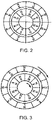
Fig. 1 is closest to this technical solution. The magnetic coupling is composed of external magnets, internal magnets and a shielding case. The internal magnets and the external magnets are composed of permanent magnets which are magnetized along a radial direction and having opposite magnetization directions. The permanent magnets are alternately arranged in circumferential directions with different polarities, and fixed on low carbon steel rings to form a magnetic circuit breaker continuum. The shielding case is made of non-ferritic (and thus non-magnetic) high resistance material. At a stationary state, the N poles (S poles) of the external magnets and the S poles (N poles) of the internal magnets attract each other and form a straight line; and at this moment, the torque is zero, as shown inFig. 2 . When the external magnets rotate under the drive of a power machine, the internal magnets are still at the stationary state at the beginning due to the action of a frictional force and resistance of a transmitted part; at this moment, the external magnets start to deviate from the internal magnets by a certain angle; due to the existence of the angle, the N pole (S pole) of the external magnets has a pulling effect on the S pole (N pole) of the internal magnets, and the N pole (S pole) of the external magnets has a pushing effect on the previous N pole (S pole) of the internal magnets, so as to drive the internal magnets to rotate, as shown inFig. 3 . In a transmission process, the shielding case separates the external magnets from the internal magnets. The magnetic lines of force pass through shielding case to transfer the power and motion of the external magnets to the internal magnets, thereby realizing non-contact static seal transmission. - In addition, a magnetic coupling disclosed in Chinese patent
CN104242599 Ais also the prior art closest to the technical solution, comprising adriving shaft 1, a drivenshaft 2, anouter rotor 3 and an inner rotor 4. Thedriving shaft 1 is fixedly connected with theouter rotor 3; the drivenshaft 2 is fixedly connected with the inner rotor 4; and an isolating sleeve is arranged between theouter rotor 3 and the inner rotor 4. Four drivenpermanent magnets 6 are fixed on the outer surface of the inner rotor 4, and correspondingpermanent magnets 7 are also arranged at the inner side of theouter rotor 3 along the axial direction. - Thus, in the above prior art, the inner rotor and the outer rotor provide magnetic forces through the arrangement of the permanent magnets, and the shielding case is installed between the inner rotor and the outer rotor for sealing.
- Problems in the prior art: the inner rotor and the outer rotor adopt the permanent magnets with strong magnetism in the prior art; a little carelessness in the installation process will make the permanent magnets of the inner rotor and the outer rotor attract together and difficult to separate; a large attraction force can even cause damage to the permanent magnets, thereby increasing installation difficulty; Once the permanent magnets are magnetized, the magnetic characteristics are determined and the transfer torque of the coupling cannot be adjusted. Therefore, different couplings need to be customized according to different loads, and the product has poor universality; and moreover, when overloading occurs, sliding failure may appear. In order to maximize the universal range, the maximum magnetic characteristics of the permanent magnets are usually used to increase the maximum transfer torque of the coupling, resulting in waste of resources. When the torque is increased, the electromagnetic stiffness between the inner rotor and the outer rotor may be increased, resulting in poor cushioning and damping effects of the coupling. In addition, due to the existence of the shielding case, a working air gap of a magnetic circuit between the inner rotor and the outer rotor may be increased, thereby affecting the working magnetic field strength so that the magnetic coupling is limited in application because of too small transfer torque.
- In conclusion, the prior art has the problems of too small and unadjustable transfer torque, poor universality, difficult installation, easy damage and poor cushioning and damping effects.
- In view of the above problems in the prior art, the technical solution of the patent of the present invention is intended to break the structural form of the prior art and design a novel magnetic coupling with large and variable torque, convenient and reliable installation, better cushioning and damping effects, strong universality and wide application range.
- The magnetic coupling and the use and adjustment method thereof provided by the present invention realize variable transfer torque of the magnetic coupling, change the size of the transfer torque so that the coupling is applicable to operating conditions and occasions with different transfer torque requirements, enhance the universality of the coupling, realize overload protection and achieve better cushioning and damping effects. The present invention is convenient and reliable in installation, widens the application range of the magnetic coupling, realizes overall sealing, omits a shielding case in the magnetic coupling, reduces an operating air gap and increases the transfer torque.
- To achieve the above purpose, the present invention adopts the following technical solution:
The magnetic coupling connects a driving shaft of a driving body and a driven shaft of a driven body and comprises a driving rotor sleeved on the driving shaft, a driven rotor sleeved on the driven shaft, external magnets mounted on the driving rotor and internal magnets mounted on the driven rotor and located on the inner sides of the external magnets; a plurality of internal magnets are arranged and uniformly distributed along the circumferential direction of the driven rotor; the external magnets and the internal magnets are aligned one by one along a radial direction; the internal magnets and the external magnets are magnetized along the radial direction; adjacent internal magnets have opposite magnetizing directions, and adjacent external magnets have opposite magnetizing directions; magnetic poles of the internal magnets are opposite to magnetic poles of the corresponding external magnets, and the driving rotor and the driven rotor form a working magnetic circuit through a magnetic field generated by the external magnets and a magnetic field generated by the internal magnets, wherein at least the external magnets are magnet exciting coils that generate a working magnetic field through power supply. - Preferably, the internal magnets are permanent magnets, and the external magnets are the magnet exciting coils that generate the working magnetic field through power supply; the driving rotor is of a tubular structure, and an inner end is sleeved on the driving shaft; the internal magnets are uniformly attached to the outer peripheral surface of the driven rotor along the circumferential direction and extend into an inner cavity of the driving rotor along the axial direction; the external magnets are mounted on the inner wall of the driving rotor and are aligned with the internal magnets one by one along the radial direction without contact; the driving rotor is provided with a conducting slip ring device that powers the external magnets; and the conducting slip ring device is electrically connected with the external magnets and an external power supply.
- Preferably, the inner wall of the driving rotor is provided with winding flanges arranged along the axial direction and corresponding to the internal magnets one by one; the winding flanges protrude inwards along the radial direction from the inner wall of the driving rotor; and the magnet exciting coils are wound along the axial direction on the winding flanges to form the external magnets.
- Preferably, the inner wall of the driving rotor is provided with annular planes arranged along the radial direction; the annular planes are separated from the winding flanges along the axial direction; the magnet exciting coils are wound on the winding flanges along the axial direction and the axial inner ends are in contact with the annular planes; and the axial outer ends are flush with the outer end of the driving rotor.
- Preferably, the conducting slip ring device comprises a hollow shaft sleeved on the driving rotor, slip rings tightly sleeved on the hollow shaft, and an electric brush installed outside the hollow shaft and in elastic contact with the slip rings; a plurality of slip rings are arranged and uniformly distributed along the axial direction of the hollow shaft; the slip rings are electrically connected with the external magnets through conducting wires; one end of the electric brush is in elastic contact with the slip rings, and the other end can be connected with the external power supply; and the electric brush moves on the slip rings to conduct current with the rotation of the slip rings.
- Preferably, an insulating sleeve is sleeved on the hollow shaft; the slip rings are tightly sleeved on the insulating sleeve; and adjacent slip rings are separated along the axial direction without contact.
- Preferably, the insulating sleeve is provided with annular grooves corresponding to the slip rings; the slip rings are embedded into the annular grooves; and one end of the electric brush extends into the annular grooves and come into elastic contact with the slip rings.
- Preferably, the conducting slip ring device also comprises a brush frame installed outside the hollow shaft; one end of the electric brush away from the slip rings is connected to the brush frame; the brush frame is provided with a spring corresponding to the electric brush; the electric brush is in elastic contact with the slip rings through the pressing force of the spring; the brush frame is provided with a wiring terminal that can be connected with the external power supply; and the wiring terminal is electrically connected with the electric brush.
- Preferably, the conducting slip ring device also comprises a stator; the brush frame is installed outside the hollow shaft through the stator; the stator is coaxially arranged around the hollow shaft, and both ends are in seal fit connection with the driving body and the driven body respectively; and the brush frame is fixed to the stator.
- In the use and adjustment method of the magnetic coupling, the current magnitude of the external magnets is adjusted according to the requirements for the transfer torque in the use conditions to adjust the transfer torque of the magnetic coupling and electromagnetic stiffness, so as to realize overload protection, cushioning and damping for the magnetic coupling.
- The present invention has the following beneficial effects:
- 1. In the present invention, at least the external magnets are the magnet exciting coils that generate the working magnetic field through power supply. In the stationary state, the magnet exciting coils are charged with direct current to form an electromagnetic field; directions of magnetic lines of force are distributed radially; the internal magnets have magnetic poles opposite to the magnetic poles of the external magnets, and the internal magnets and the external magnets attract each other to form straight lines; and at this moment, the torque is zero. When the external magnets rotate under the drive of the driving shaft, the driven rotor is still at the stationary state at the beginning; at this moment, the corresponding external magnets start to deviate from the internal magnets by a certain angle; due to the existence of the angle, the N pole (S pole) of the external magnets has a pulling effect on the S pole (N pole) of the internal magnets, and the N pole (S pole) of the external magnets has a pushing effect on the previous N pole (S pole) of the internal magnets, so as to drive the driven rotor containing the internal magnets to rotate, thereby realizing the transfer of power and movement. At least the external magnets use the magnet exciting coils to provide the magnetic force, and the magnet exciting coils control the change of the magnetic field by changing the current, so that the transfer torque of the magnetic coupling is variable and the coupling is applicable to operating conditions and occasions with different transfer torque requirements by changing the size of the transfer torque, thereby enhancing the universality of the coupling.
- 2. When the machine is overloaded, the torque can be increased by changing the current magnitude to avoid failure or slipping phenomenon of the coupling and realize overload protection and more reliability. The magnetic coupling can ensure the transfer torque and match and design the optimal electromagnetic stiffness parameters by controlling the current magnitude of the magnet exciting coils according to the vibration and impact characteristics of the actual application conditions, thereby achieving better cushioning and damping effects.
- 3. Because the magnet exciting coils have no magnetism before electrified, the driving rotor can be easily installed in alignment with the driven rotor without electrification, and then electrified after being placed in a good position. The installation is convenient and reliable, and the shielding case between the internal magnets and the external magnets is omitted. Static seal of the magnetic coupling is realized by the stator of the conducting slip ring device, and the working air gap of the magnetic circuit between two rotors is minimized, thereby enhancing the working magnetic field, increasing the transfer torque and widening the application range of the magnetic coupling.
- 4. To power the magnet exciting coils of the outer rotor, the conducting slip ring device is adopted in the present invention. The device is installed separately, and is simple in structure and convenient in installation. Moreover, a stator part is respectively connected with the bodies at the driving side and the driven side to achieve the overall seal, omit the shielding case in the magnetic coupling, reduce the working air gap and increase the transfer torque.
-
-
Fig. 1 is a structural schematic diagram of a magnetic coupling in the prior art. -
Fig. 2 is a distribution diagram of a magnetic circuit when a magnetic coupling inFig. 1 is in a stationary state. -
Fig. 3 is a distribution diagram of a magnetic circuit when a magnetic coupling inFig. 1 rotates. -
Fig. 4 is a structural schematic diagram of a magnetic coupling in the present invention. -
Fig. 5 is a structural schematic diagram of a conducting slip ring device. -
Fig. 6 is a stereogram of a conducting slip ring device without a stator. - Embodiments of the present invention are described in detail below in combination with
Fig. 4 to Fig. 6 . - A magnetic coupling connects a driving
shaft 3 of a drivingbody 1 and a driven shaft 4 of a drivenbody 2 and comprises a drivingrotor 5 sleeved on the drivingshaft 3, a drivenrotor 6 sleeved on the driven shaft 4,external magnets 7 mounted on the drivingrotor 5 andinternal magnets 8 mounted on the drivenrotor 6 and located on the inner sides of theexternal magnets 7; a plurality ofinternal magnets 8 are arranged and uniformly distributed along the circumferential direction of the drivenrotor 6; theexternal magnets 7 and theinternal magnets 8 are aligned one by one along a radial direction; theinternal magnets 8 and theexternal magnets 7 are magnetized along the radial direction; adjacentinternal magnets 8 have opposite magnetizing directions, and adjacentexternal magnets 7 have opposite magnetizing directions; magnetic poles of theinternal magnets 8 are opposite to magnetic poles of the correspondingexternal magnets 7, and the drivingrotor 5 and the drivenrotor 6 form a working magnetic circuit through a magnetic field generated by theexternal magnets 7 and a magnetic field generated by theinternal magnets 8, wherein at least theexternal magnets 7 are magnet exciting coils that generate a working magnetic field through power supply. - In the above magnetic coupling, at least the
external magnets 7 are the magnet exciting coils that generate the working magnetic field through power supply. In the stationary state, the magnet exciting coils are charged with direct current to form an electromagnetic field; directions of magnetic lines of force are distributed radially; theinternal magnets 8 have magnetic poles opposite to the magnetic poles of theexternal magnets 7, and the internal magnets and the external magnets attract each other to form straight lines; and at this moment, the torque is zero. When theexternal magnets 7 rotate under the drive of the drivingshaft 1, the drivenrotor 2 is still at the stationary state at the beginning; at this moment, the correspondingexternal magnets 7 start to deviate from theinternal magnets 8 by a certain angle; due to the existence of the angle, the N pole (S pole) of the external magnets has a pulling effect on the S pole (N pole) of the internal magnets, and the N pole (S pole) of the external magnets has a pushing effect on the previous N pole (S pole) of the internal magnets, so as to drive the drivenrotor 6 containing theinternal magnets 8 to rotate, thereby realizing the transfer of power and movement. At least theexternal magnets 7 use the magnet exciting coils to provide the magnetic force, and the magnet exciting coils control the change of the magnetic field by changing the current, so that the transfer torque of the magnetic coupling is variable and the coupling is applicable to operating conditions and occasions with different transfer torque requirements by changing the size of the transfer torque, thereby enhancing the universality of the coupling. When the machine is overloaded, the torque can be increased by changing the current magnitude to avoid failure or slipping phenomenon of the coupling and realize overload protection and more reliability. The magnetic coupling can ensure the transfer torque and match and design the optimal electromagnetic stiffness parameters by controlling the current magnitude of the magnet exciting coils according to the vibration and impact characteristics of the actual application conditions, thereby achieving better cushioning and damping effects. Because the magnet exciting coils have no magnetism before electrified, the outer rotor can be easily installed in alignment with the inner rotor without electrification, and then electrified after being placed in a good position. The installation is convenient and reliable, and the shielding case between the internal magnets and the external magnets is omitted. The working air gap of the magnetic circuit between two rotors is minimized, thereby enhancing the working magnetic field, increasing the transfer torque and widening the application range of the magnetic coupling. - The
internal magnets 8 are permanent magnets, and theexternal magnets 7 are the magnet exciting coils that generate the working magnetic field through power supply; the drivingrotor 5 is of a tubular structure, and an inner end is sleeved on the drivingshaft 3; theinternal magnets 8 are uniformly attached to the outer peripheral surface of the drivenrotor 6 along the circumferential direction and extend into an inner cavity of the drivingrotor 5 along the axial direction; theexternal magnets 7 are mounted on the inner wall of the drivingrotor 5 and are aligned with theinternal magnets 8 one by one along the radial direction without contact; the drivingrotor 5 is provided with a conducting slip ring device 9 that powers theexternal magnets 7; and the conducting slip ring device 9 is electrically connected with theexternal magnets 7 and an external power supply to realize circuit connection of the external power supply, the conducting slip ring device and the magnet exciting coils. - The inner wall of the driving
rotor 5 is provided with windingflanges 51 arranged along the axial direction and corresponding to theinternal magnets 8 one by one; the windingflanges 51 protrude inwards along the radial direction from the inner wall of the drivingrotor 5; and the magnet exciting coils are wound along the axial direction on the windingflanges 51 to form theexternal magnets 7. The windingflanges 51 are used for winding the magnet exciting coils. The windingflanges 51 are radial bulges and arranged along the axial direction for the convenience of winding the magnet exciting coils along the axial direction. The quantity of the windingflanges 51 is equal to the quantity of theinternal magnets 8 and form one-to-one correspondence, so as to form theexternal magnets 7 that are in one-to-one correspondence with theinternal magnets 8. - The inner wall of the driving
rotor 5 is provided withannular planes 52 arranged along the radial direction; theannular planes 52 are separated from the windingflanges 51 along the axial direction; the magnet exciting coils are wound on the windingflanges 51 along the axial direction and the axial inner ends are in contact with theannular planes 52; and the axial outer ends are flush with the outer end of the drivingrotor 5. Theannular planes 52 are used for determining the axial thickness of the magnet exciting coils. When the magnet exciting coils are wound to come into contact with theannular planes 52, axial thickening is stopped. When the axial inner ends of the magnet exciting coils come into contact with theannular planes 52, the axial outer ends are just flush with the end parts of the drivingrotor 5 to ensure that the winding of the magnet exciting coils does not exceed the limit. The winding formation of theexternal magnets 7 is more maneuverable. The sizes of the formed plurality ofexternal magnets 7 are consistent to enhance the circumferential uniformity of the magnetic circuit of the internal magnets and the external magnets. - The conducting slip ring device 9 comprises a
hollow shaft 91 sleeved on the drivingrotor 5, slip rings 92 tightly sleeved on thehollow shaft 91, and anelectric brush 93 installed outside thehollow shaft 91 and in elastic contact with the slip rings 92; a plurality ofslip rings 92 are arranged and uniformly distributed along the axial direction of thehollow shaft 91; the slip rings 92 are electrically connected with theexternal magnets 7 through conducting wires; one end of theelectric brush 93 is in elastic contact with the slip rings 92, and the other end can be connected with the external power supply; and theelectric brush 93 moves on the slip rings 92 to conduct current with the rotation of the slip rings 92. When the drivingshaft 3 rotates, the drivingrotor 5 is driven to rotate, and thehollow shaft 91 rotates with the drivingrotor 5. One end of the electric brush 22 contacts and moves on the slip rings 92 to form an electrically conductive path of the external power supply, the electric brush, the slip rings and the magnet exciting coils to power the magnet exciting coils. The conductive current of the external power supply is adjusted to adjust the current of the magnet exciting coils, to change the magnetic field strength generated by the magnet exciting coils and control the magnetic field change of theexternal magnets 7, thereby changing the transfer torque between the internal magnets and the external magnets to adapt to operating conditions and occasions with different transfer torque requirements. - An insulating
sleeve 94 is sleeved on thehollow shaft 91; the slip rings 92 are tightly sleeved on the insulatingsleeve 94; andadjacent slip rings 92 are separated along the axial direction without contact. The insulatingsleeve 94 insulates theadjacent slip rings 92 and insulates the slip rings 92 and thehollow shaft 91 to improve the safety of conduction. - Specifically, the insulating
sleeve 94 is provided with annular grooves 94.1 corresponding to the slip rings 92; the slip rings 92 are embedded into the annular grooves 94.1; and one end of theelectric brush 93 extends into the annular grooves 94.1 and come into elastic contact with the slip rings 92. The annular grooves 94.1 are formed in the insulatingsleeve 94, so that theadjacent slip rings 92 are completely insulated and the sleeving positions of the slip rings 92 are effectively located to ensure that the slip rings 92 may not deviate in the use process. Meanwhile, theelectric brush 93 extends into the annular grooves 94.1 and come into contact with the slip rings 92; and the annular grooves 94.1 are used for limiting the contact end part of theelectric brush 93 to ensure that theelectric brush 93 and the slip rings 92 come into one-to-one contact. In the brushing process, the position of theelectric brush 93 is located by the annular grooves 94.1 and may not deviate or separate from the corresponding slip rings 92. The structural reliability of the conducting slip ring device 9 is higher; effectiveness and reliability of conduction are higher; and the one-to-one assembling structures of theelectric brush 93 and the slip rings 92 are easier to be realized. - The conducting slip ring device 9 also comprises a
brush frame 95 installed outside thehollow shaft 91; one end of theelectric brush 93 away from the slip rings 92 is connected to thebrush frame 95; thebrush frame 95 is provided with a spring corresponding to theelectric brush 93; theelectric brush 93 is in elastic contact with the slip rings 92 through the pressing force of the spring; thebrush frame 95 is provided with awiring terminal 96 that can be connected with the external power supply; and thewiring terminal 96 is electrically connected with theelectric brush 93. The spring on thebrush frame 95 presses theelectric brush 93 so that theelectric brush 93 is always in elastic contact with the slip rings 92. Moreover, thewiring terminal 96 is installed on thebrush frame 95, which is easy to realize the connection between the external power supply and theelectric brush 93, so that the conducting slip ring device 9 is simple in structure and easy to realize installation and wiring. - The conducting slip ring device 9 also comprises a
stator 97; thebrush frame 95 is installed outside thehollow shaft 91 through thestator 97; thestator 97 is coaxially arranged around thehollow shaft 91, and both ends are in seal fit connection with the drivingbody 1 and the drivenbody 2 respectively; and thebrush frame 95 is fixed to thestator 97. Through the arrangement of thestator 97, static seal of the magnetic coupling is realized; the shielding case between the internal magnets and the external magnets is omitted; and the working air gap of the magnetic circuit between the inner rotor and the outer rotor is minimized, thereby enhancing the working magnetic field, increasing the transfer torque and widening the application range of the magnetic coupling. Moreover, thebrush frame 95 is fixed on thestator 97, which can ensure that thebrush frame 95 may not rotate due to the rotation of thehollow shaft 91. The structural reliability of the conducting slip ring device 9 is higher. The conducting slip ring device 9 can be installed only through the separate installation of thehollow shaft 91 and the drivingrotor 5. The structure is simple and the installation is convenient. Thestator 97 is respectively connected with the body at the driving side and the body at the driven side to achieve the overall seal, omit the shielding case in the magnetic coupling, reduce the working air gap and increase the transfer torque. - In the use and adjustment method of the magnetic coupling, the current magnitude of the
external magnets 7 is adjusted according to the requirements for the transfer torque in the use conditions to adjust the transfer torque of the magnetic coupling and electromagnetic stiffness, so as to realize overload protection, cushioning and damping for the magnetic coupling. - In the above adjustment method, the magnet exciting coils of the
external magnets 7 control the change of the magnetic field by changing the current, so that the transfer torque of the magnetic coupling is variable and the coupling is applicable to operating conditions and occasions with different transfer torque requirements by changing the size of the transfer torque, thereby enhancing the universality of the coupling. When the machine is overloaded, the torque is increased by changing the current magnitude to avoid failure or slipping phenomenon of the coupling and realize overload protection and more reliability. The magnetic coupling can ensure the transfer torque and match and design the optimal electromagnetic stiffness parameters by controlling the current magnitude of the magnet exciting coils according to the vibration and impact characteristics of the actual application conditions, thereby achieving better cushioning and damping effects. - The technical solutions of the embodiments of the present invention are fully described above in combination with the drawings. It should be noted that the described embodiments are merely part of the embodiments of the present invention. Based on the embodiments in the present invention, all other embodiments obtained by those ordinary skilled in the art without contributing creative labor will belong to the protection scope of the present invention.
Claims (10)
- A magnetic coupling, wherein the magnetic coupling connects a driving shaft (3) of a driving body (1) and a driven shaft (4) of a driven body (2), the magnetic coupling comprises a driving rotor (5) sleeved on the driving shaft (3), a driven rotor (6) sleeved on the driven shaft (4), external magnets (7) mounted on the driving rotor (5) and internal magnets (8) mounted on the driven rotor (6) and located on the inner sides of the external magnets (7); a plurality of internal magnets (8) are arranged and uniformly distributed along a circumferential direction of the driven rotor (6); the external magnets (7) and the internal magnets (8) are aligned one by one along a radial direction; the internal magnets (8) and the external magnets (7) are magnetized along the radial direction; adjacent internal magnets (8) have opposite magnetizing directions, and adjacent external magnets (7) have opposite magnetizing directions; magnetic poles of the internal magnets (8) are opposite to magnetic poles of the corresponding external magnets (7), and the driving rotor (5) and the driven rotor (6) form a working magnetic circuit through a magnetic field generated by the external magnets (7) and a magnetic field generated by the internal magnets (8), characterized in that at least the external magnets (7) are magnet exciting coils that generate a working magnetic field through power supply.
- The magnetic coupling according to claim 1, characterized in that the internal magnets (8) are permanent magnets, and the external magnets (7) are the magnet exciting coils that generate the working magnetic field through power supply; the driving rotor (5) is of a tubular structure, and an inner end is sleeved on the driving shaft (3); the internal magnets (8) are uniformly attached to an outer peripheral surface of the driven rotor (6) along a circumferential direction and extend into an inner cavity of the driving rotor (5) along an axial direction; the external magnets (7) are mounted on an inner wall of the driving rotor (5) and are aligned with the internal magnets (8) one by one along the radial direction without contact; the driving rotor (5) is provided with a conducting slip ring device (9) that powers the external magnets (7); and the conducting slip ring device (9) is electrically connected with the external magnets (7) and an external power supply.
- The magnetic coupling according to claim 2, characterized in that the inner wall of the driving rotor (5) is provided with winding flanges (51) arranged along the axial direction and corresponding to the internal magnets (8) one by one; the winding flanges (51) protrude inwards along the radial direction from the inner wall of the driving rotor (5); and the magnet exciting coils are wound along the axial direction on the winding flanges (51) to form the external magnets (7).
- The magnetic coupling according to claim 3, characterized in that the inner wall of the driving rotor (5) is provided with annular planes (52) arranged along the radial direction; the annular planes (52) are separated from the winding flanges (51) along the axial direction; the magnet exciting coils are wound on the winding flanges (51) along the axial direction and the axial inner ends are in contact with the annular planes (52); and an axial outer ends are flush with an outer end of the driving rotor (5).
- The magnetic coupling according to claim 2, characterized in that the conducting slip ring device (9) comprises a hollow shaft (91) sleeved on the driving rotor (5), slip rings (92) tightly sleeved on the hollow shaft (91), and an electric brush (93) installed outside the hollow shaft (91) and in elastic contact with the slip rings (92); a plurality of slip rings (92) are arranged and uniformly distributed along an axial direction of the hollow shaft (91); the slip rings (92) are electrically connected with the external magnets (7) through conducting wires; one end of the electric brush (93) is in elastic contact with the slip rings (92), and the other end is capable of connecting with the external power supply; and the electric brush (93) moves on the slip rings (92) to conduct current with a rotation of the slip rings (92).
- The magnetic coupling according to claim 5, characterized in that an insulating sleeve (94) is sleeved on the hollow shaft (91); the slip rings (92) are tightly sleeved on the insulating sleeve (94); and adjacent slip rings (92) are separated along the axial direction without contact.
- The magnetic coupling according to claim 6, characterized in that the insulating sleeve (94) is provided with annular grooves (94.1) corresponding to the slip rings (92); the slip rings (92) are embedded into the annular grooves (94.1); and one end of the electric brush (93) extends into the annular grooves (94.1) and come into elastic contact with the slip rings (92).
- The magnetic coupling according to claim 5, characterized in that the conducting slip ring device (9) also comprises a brush frame (95) installed outside the hollow shaft (91); one end of the electric brush (93) away from the slip rings (92) is connected to the brush frame (95); the brush frame (95) is provided with a spring corresponding to the electric brush (93); the electric brush (93) is in elastic contact with the slip rings (92) through a pressing force of the spring; the brush frame (95) is provided with a wiring terminal (96) capable of connecting with the external power supply; and the wiring terminal (96) is electrically connected with the electric brush (93).
- The magnetic coupling according to claim 8, characterized in that the conducting slip ring device (9) also comprises a stator (97); the brush frame (95) is installed outside the hollow shaft (91) through the stator (97); the stator (97) is coaxially arranged around the hollow shaft (91), and both ends are in seal fit connection with the driving body (1) and the driven body (2) respectively; and the brush frame (95) is fixed to the stator (97).
- An use and adjustment method of the magnetic coupling according to any one of claims 1 to 9, characterized in a current magnitude of the external magnets (7) is adjusted according to a requirements for a transfer torque in the use conditions to adjust a transfer torque of the magnetic coupling and electromagnetic stiffness, so as to realize overload protection, cushioning and damping for the magnetic coupling.
Applications Claiming Priority (2)
| Application Number | Priority Date | Filing Date | Title |
|---|---|---|---|
| CN201911156080.9A CN110855123B (en) | 2019-11-22 | 2019-11-22 | Magnetic coupling and use adjusting method thereof |
| PCT/CN2020/127763 WO2021098548A1 (en) | 2019-11-22 | 2020-11-10 | Magnetic shaft coupling and use and adjustment method thereof |
Publications (2)
| Publication Number | Publication Date |
|---|---|
| EP4064534A1 true EP4064534A1 (en) | 2022-09-28 |
| EP4064534A4 EP4064534A4 (en) | 2024-07-03 |
Family
ID=69603651
Family Applications (1)
| Application Number | Title | Priority Date | Filing Date |
|---|---|---|---|
| EP20889997.1A Pending EP4064534A4 (en) | 2019-11-22 | 2020-11-10 | MAGNETIC SHAFT COUPLING AND METHOD OF USE AND ADJUSTMENT THEREFOR |
Country Status (4)
| Country | Link |
|---|---|
| US (1) | US11923136B2 (en) |
| EP (1) | EP4064534A4 (en) |
| CN (1) | CN110855123B (en) |
| WO (1) | WO2021098548A1 (en) |
Families Citing this family (8)
| Publication number | Priority date | Publication date | Assignee | Title |
|---|---|---|---|---|
| CN110855123B (en) * | 2019-11-22 | 2022-03-18 | 株洲时代新材料科技股份有限公司 | Magnetic coupling and use adjusting method thereof |
| CN112121748B (en) * | 2020-09-15 | 2022-05-20 | 胜利油田物华化工厂 | Torque heightening mechanism of reaction kettle magnetic coupling |
| CN113898605B (en) * | 2021-11-10 | 2023-10-13 | 安徽银龙泵阀股份有限公司 | Sealed magnetic drive pump isolation sleeve |
| CN114738193A (en) * | 2022-05-11 | 2022-07-12 | 青岛润华士科技有限公司 | Wind power heating system and wind power type heating method thereof |
| CN115250050A (en) * | 2022-08-11 | 2022-10-28 | 包头市英思特稀磁新材料股份有限公司 | Magnet with focusing magnetic field distribution, manufacturing method thereof and magnetic coupling |
| CN116566161A (en) * | 2022-09-14 | 2023-08-08 | 中国科学院理化技术研究所 | A Non-contact Shafting Structure of Low-Temperature Rotating Machinery |
| CN116145129B (en) * | 2022-12-30 | 2024-07-26 | 贵州大学 | Electromagnetic auxiliary high-speed rotating shaft laser cladding test device |
| CN116345845B (en) * | 2023-02-23 | 2026-03-24 | 浙江大学 | A self-centering compensated permanent magnet synchronous coupling based on segmented coils |
Family Cites Families (24)
| Publication number | Priority date | Publication date | Assignee | Title |
|---|---|---|---|---|
| CN1299019C (en) * | 2005-04-14 | 2007-02-07 | 西安理工大学 | Non contact flexible magnetic coupling for vacuum system |
| DE102005031413B4 (en) * | 2005-07-04 | 2009-06-25 | Oldenburg, Jörg, Prof. Dr. | Stepless electric transmission |
| CN100492785C (en) | 2007-04-29 | 2009-05-27 | 北京航天控制仪器研究所 | Radial insulation laminated conductive slip ring |
| CN101391330B (en) * | 2008-11-06 | 2011-03-16 | 哈尔滨工程大学 | Gas-electricity one-piece slip-ring |
| CN101931308B (en) * | 2009-06-22 | 2012-09-26 | 余亚莉 | Permanent magnet coupling device for cylindrical transmission shaft |
| CN201478983U (en) * | 2009-06-22 | 2010-05-19 | 余亚莉 | Permanent magnetic coupling device of cylindrical transmission shaft |
| JP5618610B2 (en) * | 2010-04-28 | 2014-11-05 | 日本信号株式会社 | Torque transmission device and turning machine using the same |
| CN101873053B (en) * | 2010-06-24 | 2012-02-22 | 大连理工大学 | Flexible Electromagnetic Coupling Torque Transfer Method for Electric Vehicles |
| CN102624198B (en) * | 2012-04-20 | 2014-03-19 | 林贵生 | Permanent magnetic coupling transmission, braking or load device with cooling and lubricating device |
| CN202679218U (en) | 2012-04-20 | 2013-01-16 | 林贵生 | Permanent magnetic coupling transmission, braking or load apparatus with cooling and lubricating devices |
| CN104065236B (en) * | 2013-03-22 | 2017-05-03 | 林英楠 | Permanent magnetic speed regulation, brake or load apparatus capable of stepless adjustment of magnetic field intensity |
| CN203674953U (en) | 2013-03-22 | 2014-06-25 | 林英楠 | Permanent magnet speed regulation, brake or load apparatus capable of stepless adjustment of magnetic field intensity |
| CN104242599A (en) | 2013-06-12 | 2014-12-24 | 镇江兴达联轴器有限公司 | Magnetic coupler |
| CN204144559U (en) * | 2014-08-01 | 2015-02-04 | 黄岳良 | The signal adapting device of contactless automatic car washing machine |
| CN105048235B (en) | 2015-05-19 | 2017-07-28 | 北京航天控制仪器研究所 | A kind of smooth electric combination slip ring |
| CN105720792A (en) * | 2016-03-30 | 2016-06-29 | 江苏磁谷科技股份有限公司 | Magnetic coupling |
| CN205724308U (en) * | 2016-05-04 | 2016-11-23 | 杭州驰宏科技有限公司 | A kind of adjustable slip ring structure |
| CN206060507U (en) * | 2016-08-23 | 2017-03-29 | 贾建伟 | Permanent magnetism multi-functional drum-type actuating device |
| CN106451997A (en) * | 2016-08-26 | 2017-02-22 | 诸暨和创磁电科技有限公司 | Magneto-electric speed regulator |
| CN208738583U (en) * | 2018-08-06 | 2019-04-12 | 四川省东泰机械制造有限公司 | A kind of novel conducting slip ring |
| CN209105008U (en) * | 2018-11-21 | 2019-07-12 | 国电龙源节能技术有限公司 | Winding type permanent magnet speed regulation device and its system |
| CN209071784U (en) * | 2019-01-09 | 2019-07-05 | 深圳市默孚龙科技有限公司 | A kind of conducting slip ring |
| CN109546842B (en) * | 2019-01-21 | 2024-01-30 | 诸暨和创电机科技有限公司 | Composite excitation permanent magnet speed regulator |
| CN110855123B (en) * | 2019-11-22 | 2022-03-18 | 株洲时代新材料科技股份有限公司 | Magnetic coupling and use adjusting method thereof |
-
2019
- 2019-11-22 CN CN201911156080.9A patent/CN110855123B/en active Active
-
2020
- 2020-11-10 WO PCT/CN2020/127763 patent/WO2021098548A1/en not_active Ceased
- 2020-11-10 EP EP20889997.1A patent/EP4064534A4/en active Pending
- 2020-11-10 US US17/636,362 patent/US11923136B2/en active Active
Also Published As
| Publication number | Publication date |
|---|---|
| EP4064534A4 (en) | 2024-07-03 |
| US20220285063A1 (en) | 2022-09-08 |
| US11923136B2 (en) | 2024-03-05 |
| CN110855123A (en) | 2020-02-28 |
| WO2021098548A1 (en) | 2021-05-27 |
| CN110855123B (en) | 2022-03-18 |
Similar Documents
| Publication | Publication Date | Title |
|---|---|---|
| US11923136B2 (en) | Magnetic coupling and use and adjustment method thereof | |
| CN101227130A (en) | Hybrid Excitation Synchronous Motor Directly Controlled by Rotor Field | |
| CN103607097B (en) | A kind of square position type magnetism-gathering magnetic line structure for permanent magnetic vortex drive device | |
| CN101645644B (en) | Permanent magnetic compound type asynchronous coupling | |
| CN105720792A (en) | Magnetic coupling | |
| CN105119454A (en) | Halbach array permanent magnet DC brushless motor | |
| CN104022615B (en) | Permanent magnetic DC straight-line flexible driving mechanism | |
| CN104600955A (en) | Disk type torque limiting permanent magnet coupler | |
| CN112542934A (en) | Permanent magnet speed regulator for moving magnetic steel | |
| CN103618433B (en) | A kind of socket type magnetism-gathering magnetic line structure for permanent magnetic vortex drive device | |
| CN104795964B (en) | A kind of high-speed permanent magnetic shaft coupling | |
| CN210693744U (en) | Permanent magnet eddy current transmission reaction kettle | |
| CN104682660B (en) | A magnetic gear with axial magnetic field modulation | |
| CN205490086U (en) | Magnetic shaft coupling | |
| CN103560647A (en) | Permanent magnet ring stator cylindrical linear switch reluctance motor | |
| CN109921602B (en) | Delayed starting method of magnetic coupler and delayed magnetic coupler | |
| CN102042302A (en) | High-speed hybrid magnetic suspension bearing | |
| CN110611397A (en) | flywheel energy storage device | |
| CN206072358U (en) | A kind of pyramid type coaxial-type magnetic sealing device | |
| CN105429426B (en) | A kind of magnetism-gathering magnetic mechanical couple | |
| CN203457030U (en) | Sleeve type magnet-gathering type magnetic circuit structure for permanent magnetic eddy current transmission device | |
| CN210693680U (en) | Permanent-magnet direct-drive reaction kettle | |
| CN204392067U (en) | A kind of eddy current type axially engages permanent magnet speed regulation device | |
| CN210444078U (en) | Two-stage composite direct-drive motor | |
| CN208589905U (en) | A coaxial permanent magnet transmission device |
Legal Events
| Date | Code | Title | Description |
|---|---|---|---|
| STAA | Information on the status of an ep patent application or granted ep patent |
Free format text: STATUS: THE INTERNATIONAL PUBLICATION HAS BEEN MADE |
|
| PUAI | Public reference made under article 153(3) epc to a published international application that has entered the european phase |
Free format text: ORIGINAL CODE: 0009012 |
|
| STAA | Information on the status of an ep patent application or granted ep patent |
Free format text: STATUS: REQUEST FOR EXAMINATION WAS MADE |
|
| 17P | Request for examination filed |
Effective date: 20220321 |
|
| AK | Designated contracting states |
Kind code of ref document: A1 Designated state(s): AL AT BE BG CH CY CZ DE DK EE ES FI FR GB GR HR HU IE IS IT LI LT LU LV MC MK MT NL NO PL PT RO RS SE SI SK SM TR |
|
| DAV | Request for validation of the european patent (deleted) | ||
| DAX | Request for extension of the european patent (deleted) | ||
| A4 | Supplementary search report drawn up and despatched |
Effective date: 20240603 |
|
| RIC1 | Information provided on ipc code assigned before grant |
Ipc: H01F 7/20 20060101ALI20240527BHEP Ipc: H02K 21/04 20060101ALI20240527BHEP Ipc: H02K 5/14 20060101ALI20240527BHEP Ipc: H02K 49/10 20060101AFI20240527BHEP |