EP4064530A1 - Linearantrieb mit sanfter kupplung - Google Patents
Linearantrieb mit sanfter kupplung Download PDFInfo
- Publication number
- EP4064530A1 EP4064530A1 EP21797611.7A EP21797611A EP4064530A1 EP 4064530 A1 EP4064530 A1 EP 4064530A1 EP 21797611 A EP21797611 A EP 21797611A EP 4064530 A1 EP4064530 A1 EP 4064530A1
- Authority
- EP
- European Patent Office
- Prior art keywords
- sleeve
- rotating screw
- friction sleeve
- linear actuator
- friction
- Prior art date
- Legal status (The legal status is an assumption and is not a legal conclusion. Google has not performed a legal analysis and makes no representation as to the accuracy of the status listed.)
- Granted
Links
Images

Classifications
-
- H—ELECTRICITY
- H02—GENERATION; CONVERSION OR DISTRIBUTION OF ELECTRIC POWER
- H02K—DYNAMO-ELECTRIC MACHINES
- H02K7/00—Arrangements for handling mechanical energy structurally associated with dynamo-electric machines, e.g. structural association with mechanical driving motors or auxiliary dynamo-electric machines
- H02K7/10—Structural association with clutches, brakes, gears, pulleys or mechanical starters
- H02K7/116—Structural association with clutches, brakes, gears, pulleys or mechanical starters with gears
- H02K7/1163—Structural association with clutches, brakes, gears, pulleys or mechanical starters with gears where at least two gears have non-parallel axes without having orbital motion
- H02K7/1166—Structural association with clutches, brakes, gears, pulleys or mechanical starters with gears where at least two gears have non-parallel axes without having orbital motion comprising worm and worm-wheel
-
- H—ELECTRICITY
- H02—GENERATION; CONVERSION OR DISTRIBUTION OF ELECTRIC POWER
- H02K—DYNAMO-ELECTRIC MACHINES
- H02K7/00—Arrangements for handling mechanical energy structurally associated with dynamo-electric machines, e.g. structural association with mechanical driving motors or auxiliary dynamo-electric machines
- H02K7/06—Means for converting reciprocating motion into rotary motion or vice versa
-
- F—MECHANICAL ENGINEERING; LIGHTING; HEATING; WEAPONS; BLASTING
- F16—ENGINEERING ELEMENTS AND UNITS; GENERAL MEASURES FOR PRODUCING AND MAINTAINING EFFECTIVE FUNCTIONING OF MACHINES OR INSTALLATIONS; THERMAL INSULATION IN GENERAL
- F16H—GEARING
- F16H25/00—Gearings comprising primarily only cams, cam-followers and screw-and-nut mechanisms
- F16H25/18—Gearings comprising primarily only cams, cam-followers and screw-and-nut mechanisms for conveying or interconverting oscillating or reciprocating motions
- F16H25/20—Screw mechanisms
- F16H25/24—Elements essential to such mechanisms, e.g. screws, nuts
- F16H25/2454—Brakes; Rotational locks
-
- F—MECHANICAL ENGINEERING; LIGHTING; HEATING; WEAPONS; BLASTING
- F16—ENGINEERING ELEMENTS AND UNITS; GENERAL MEASURES FOR PRODUCING AND MAINTAINING EFFECTIVE FUNCTIONING OF MACHINES OR INSTALLATIONS; THERMAL INSULATION IN GENERAL
- F16D—COUPLINGS FOR TRANSMITTING ROTATION; CLUTCHES; BRAKES
- F16D11/00—Clutches in which the members have interengaging parts
- F16D11/14—Clutches in which the members have interengaging parts with clutching members movable only axially
-
- F—MECHANICAL ENGINEERING; LIGHTING; HEATING; WEAPONS; BLASTING
- F16—ENGINEERING ELEMENTS AND UNITS; GENERAL MEASURES FOR PRODUCING AND MAINTAINING EFFECTIVE FUNCTIONING OF MACHINES OR INSTALLATIONS; THERMAL INSULATION IN GENERAL
- F16H—GEARING
- F16H25/00—Gearings comprising primarily only cams, cam-followers and screw-and-nut mechanisms
- F16H25/18—Gearings comprising primarily only cams, cam-followers and screw-and-nut mechanisms for conveying or interconverting oscillating or reciprocating motions
- F16H25/20—Screw mechanisms
-
- H—ELECTRICITY
- H02—GENERATION; CONVERSION OR DISTRIBUTION OF ELECTRIC POWER
- H02K—DYNAMO-ELECTRIC MACHINES
- H02K7/00—Arrangements for handling mechanical energy structurally associated with dynamo-electric machines, e.g. structural association with mechanical driving motors or auxiliary dynamo-electric machines
- H02K7/10—Structural association with clutches, brakes, gears, pulleys or mechanical starters
- H02K7/108—Structural association with clutches, brakes, gears, pulleys or mechanical starters with friction clutches
-
- F—MECHANICAL ENGINEERING; LIGHTING; HEATING; WEAPONS; BLASTING
- F16—ENGINEERING ELEMENTS AND UNITS; GENERAL MEASURES FOR PRODUCING AND MAINTAINING EFFECTIVE FUNCTIONING OF MACHINES OR INSTALLATIONS; THERMAL INSULATION IN GENERAL
- F16H—GEARING
- F16H25/00—Gearings comprising primarily only cams, cam-followers and screw-and-nut mechanisms
- F16H25/18—Gearings comprising primarily only cams, cam-followers and screw-and-nut mechanisms for conveying or interconverting oscillating or reciprocating motions
- F16H25/20—Screw mechanisms
- F16H2025/2031—Actuator casings
-
- F—MECHANICAL ENGINEERING; LIGHTING; HEATING; WEAPONS; BLASTING
- F16—ENGINEERING ELEMENTS AND UNITS; GENERAL MEASURES FOR PRODUCING AND MAINTAINING EFFECTIVE FUNCTIONING OF MACHINES OR INSTALLATIONS; THERMAL INSULATION IN GENERAL
- F16H—GEARING
- F16H25/00—Gearings comprising primarily only cams, cam-followers and screw-and-nut mechanisms
- F16H25/18—Gearings comprising primarily only cams, cam-followers and screw-and-nut mechanisms for conveying or interconverting oscillating or reciprocating motions
- F16H25/20—Screw mechanisms
- F16H2025/2062—Arrangements for driving the actuator
- F16H2025/2071—Disconnecting drive source from the actuator, e.g. using clutches for release of drive connection during manual control
-
- F—MECHANICAL ENGINEERING; LIGHTING; HEATING; WEAPONS; BLASTING
- F16—ENGINEERING ELEMENTS AND UNITS; GENERAL MEASURES FOR PRODUCING AND MAINTAINING EFFECTIVE FUNCTIONING OF MACHINES OR INSTALLATIONS; THERMAL INSULATION IN GENERAL
- F16H—GEARING
- F16H25/00—Gearings comprising primarily only cams, cam-followers and screw-and-nut mechanisms
- F16H25/18—Gearings comprising primarily only cams, cam-followers and screw-and-nut mechanisms for conveying or interconverting oscillating or reciprocating motions
- F16H25/20—Screw mechanisms
- F16H2025/2062—Arrangements for driving the actuator
- F16H2025/2084—Perpendicular arrangement of drive motor to screw axis
-
- F—MECHANICAL ENGINEERING; LIGHTING; HEATING; WEAPONS; BLASTING
- F16—ENGINEERING ELEMENTS AND UNITS; GENERAL MEASURES FOR PRODUCING AND MAINTAINING EFFECTIVE FUNCTIONING OF MACHINES OR INSTALLATIONS; THERMAL INSULATION IN GENERAL
- F16H—GEARING
- F16H25/00—Gearings comprising primarily only cams, cam-followers and screw-and-nut mechanisms
- F16H25/18—Gearings comprising primarily only cams, cam-followers and screw-and-nut mechanisms for conveying or interconverting oscillating or reciprocating motions
- F16H25/20—Screw mechanisms
- F16H2025/2062—Arrangements for driving the actuator
- F16H2025/209—Arrangements for driving the actuator using worm gears
-
- F—MECHANICAL ENGINEERING; LIGHTING; HEATING; WEAPONS; BLASTING
- F16—ENGINEERING ELEMENTS AND UNITS; GENERAL MEASURES FOR PRODUCING AND MAINTAINING EFFECTIVE FUNCTIONING OF MACHINES OR INSTALLATIONS; THERMAL INSULATION IN GENERAL
- F16H—GEARING
- F16H25/00—Gearings comprising primarily only cams, cam-followers and screw-and-nut mechanisms
- F16H25/18—Gearings comprising primarily only cams, cam-followers and screw-and-nut mechanisms for conveying or interconverting oscillating or reciprocating motions
- F16H25/20—Screw mechanisms
- F16H25/24—Elements essential to such mechanisms, e.g. screws, nuts
- F16H25/2454—Brakes; Rotational locks
- F16H2025/2463—Brakes; Rotational locks using a wrap spring brake, i.e. a helical wind up spring for braking or locking
Definitions
- the present invention relates to a linear actuator with smooth clutch, belonging to the technical field of linear transmission.
- Linear actuator also known as electric push rod
- Its main structure includes a drive motor, a drive worm, a worm gear, a screw and a nut.
- the drive motor drives the drive worm to rotate
- the drive worm meshes with the worm gear to drive the worm gear to rotate
- the worm gear rotates to drive the screw to rotate
- the screw rotates to drive the nut to move axially.
- the nut is generally connected with an inner tube, thereby achieving the telescopic movement of the inner tube.
- a clutch means will be added to the linear actuator.
- the clutch means is mainly used to cut off the power between the drive motor and the rotating screw, so that the reverse push can be achieved by manually driving the rotating screw to rotate.
- the technical problem to be solved by the present invention is that the present invention overcomes the deficiency of the prior art and provides a linear actuator with smooth clutching, so that the clutch means has better smoothness when being driven.
- the present invention adopts the following technical solution:
- a linear actuator includes a housing, a drive worm, a rotating screw and a drive nut, the drive worm driving the rotating screw to rotate, the rotating screw rotating to drive the drive nut to move axially along the rotating screw, a clutch means being arranged between the drive worm and the rotating screw, wherein the clutch means includes a coupling gear sleeve axially movable relative to the rotating worm, the rotating screw is sleeved with an axial limiting sleeve, the axial limiting sleeve and the housing are abutted axially, and the axial limiting sleeve and the rotating screw maintain alignment in an axial direction, when the rotating screw is subjected to an axial load, the rotating screw transmits axial force to the housing through the axial limiting sleeve, and the axial force is not transmitted between the coupling gear sleeve and the axial limiting sleeve in the axial direction.
- the clutch means includes a coupling gear
- the linear actuator in the present invention is provided with a clutch means, which is mainly implemented by driving the axial movement of the coupling gear sleeve, so that it is optimal for the coupling gear sleeve to be subjected to forces from the driving member only, avoiding or reducing axial forces from other components as much as possible.
- the axial force of other components mainly comes from the rotating screw, the rotating screw pushes the target to be pushed through the drive nut, and the target to be pushed may naturally react the bearing capacity to the rotating screw. If the rotating screw transmits the axial force to the coupling gear sleeve of the clutch means, the resistance may increase when the user needs to toggle the coupling gear sleeve, and the clutch means will be easily damaged after long-term use.
- the axial limiting sleeve is sleeved outside the rotating screw, and the axial limiting sleeve itself is axially limited to the rotating screw.
- the axial limiting sleeve is also axially limited with the housing.
- the axial force on the rotating screw can be transmitted to the housing through the axial limiting sleeve, while the axial force is not transmitted between the coupling gear sleeve and the axial limiting sleeve, therefore, the coupling gear sleeve will not be subjected to the axial force from the rotating screw, and the user will save labor when using the driving member to toggle the coupling gear sleeve, and at the same time, the strength requirement of the coupling gear sleeve itself is also reduced, which is also beneficial to prolonging the service life of the clutch means.
- the linear actuator further includes a first friction sleeve and a self-locking torsion spring sleeved outside the first friction sleeve, and the axial limiting sleeve includes the first friction sleeve.
- the linear actuator further includes a second friction sleeve, the first friction sleeve and the second friction sleeve are abutted axially, the second friction sleeve is sleeved with a release torsion spring, and the axial limiting sleeve includes the first friction sleeve and the second friction sleeve.
- first friction sleeve and the second friction sleeve are axially arranged side by side, and outer end faces of the first friction sleeve and the second friction sleeve abut against each other.
- the second friction sleeve is sleeved outside the first friction sleeve, and an outer end face of the first friction sleeve abuts against an inner end face of the second friction sleeve.
- the second friction sleeve is provided with a bearing
- the housing is provided with a bearing groove for mounting the bearing
- the bearing is axially limited with the housing.
- the first friction sleeve is sleeved at an end portion of the rotating screw, and the housing includes a tail puller at the end portion, and the tail puller is axially limited with the second friction sleeve.
- a spline sleeve is arranged between the rotating screw and the coupling gear sleeve, and the spline sleeve is axially limited with the first friction sleeve, and the axial limiting sleeve includes the spline sleeve, the first friction sleeve and the second friction sleeve.
- a tapered roller bearing is arranged between the second friction sleeve and the tail puller.
- the linear actuator further includes a hand-pulling release assembly
- the hand-pulling release assembly further includes a pull rod and a swing link, the pull rod being axially movable relative to the rotating screw, the swing link being rotationally connected with the pull rod, and when the pull rod is pulled, the swing link swings to axially push the coupling gear sleeve.
- the embodiment is a linear actuator.
- Linear actuators are also commonly called linear actuators or electric push rods.
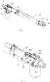
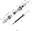
- the linear actuator includes a housing, an outer tube 13, an inner tube 14, a drive motor 15, a gearing assembly, a rotating screw 20 and a drive nut 21.
- the drive motor 15 drives the rotating screw 20 to rotate through the gearing assembly.
- the rotating screw 20 rotates to drive the drive nut 21 to move axially along the rotating screw 20, and the drive nut 21 is fixedly connected with the inner tube 14.
- the linear actuator in this embodiment further includes:
- a clutch means is arranged between the gearing assembly and the rotating screw 20 for connecting or cutting off the power connection between the gearing assembly and the rotating screw 20.
- the clutch means includes a coupling gear sleeve 31, the coupling gear sleeve 31 itself is fitted with the rotating screw 20 through a flat position. That is, in a circumferential direction, the coupling gear sleeve 31 and the rotating screw 20 rotate synchronously, but the coupling gear sleeve 31 is axially movable along the rotating screw 20 in the axial direction.
- the coupling tooth sleeve 31 has a plurality of tooth-shaped parts in a direction of the drive worm 21, an end face of the drive worm 21 is provided with a tooth space matched with the coupling gear sleeve 31 for transmission.
- the coupling tooth sleeve 31 When the coupling tooth sleeve 31 is close to the drive worm 21, the tooth-shaped parts are inserted into the tooth space, and the coupling tooth sleeve 31 and the drive worm 21 rotate synchronously. When the coupling tooth sleeve 31 is far away from the drive worm 21, the tooth-shaped parts are separated from the tooth space, and the coupling tooth sleeve 31 is separated from the drive worm 21, that is, the rotating screw 20 will be in a state of no power connection. Referring to FIG. 4 , the coupling gear sleeve 31 is inserted into the drive worm 21.
- the rotating screw 20 is sleeved with an axial limiting sleeve, the axial limiting sleeve and the housing are abutted axially, and the axial limiting sleeve and the rotating screw 20 maintain alignment in an axial direction, when the rotating screw 20 is subjected to an axial load, the rotating screw 20 transmits axial force to the housing through the axial limiting sleeve, and the axial force is not transmitted between the coupling gear sleeve 31 and the axial limiting sleeve in the axial direction.
- the axial limiting sleeve is sleeved outside the rotating screw 20, and the axial limiting sleeve itself is axially limited to the rotating screw. Secondly, the axial limiting sleeve is also axially limited with the housing.
- the axial force on the rotating screw can be transmitted to the housing through the axial limiting sleeve, while the axial force is not transmitted between the coupling gear sleeve 31 and the axial limiting sleeve, therefore, the coupling gear sleeve 31 will not be subjected to the axial force from the rotating screw, and the user will save labor when using the driving member to toggle the coupling gear sleeve 31, and at the same time, the strength requirement of the coupling gear sleeve 31 itself is also reduced, which is also beneficial to prolonging the service life of the clutch means.
- the linear actuator further includes a self-locking device, which generates frictional resistance to the rotating screw 20 when the rotating screw 20 rotates reversely.
- the structure of the self-locking device in this embodiment is as follows: the self-locking device includes a first friction sleeve 41, a second friction sleeve 42, a release torsion spring 40, a self-locking torsion spring 43, the first friction sleeve 41 and the second friction sleeve 42 are respectively sleeved on the rotating screw 20, the first friction sleeve 41 and the rotating screw 20 are positioned in a flat position, that is, in the circumferential direction, the first friction sleeve 41 and the rotating screw 20 rotate synchronously, while the second friction sleeve 42 rotates freely relative to the rotating screw 20, and in the axial direction, axial end faces of the first friction sleeve 41 and the second friction sleeve 42 abut against each other.
- the release torsion spring 40 is sleeved on the second friction sleeve 42, and the release torsion spring 40 clasps the second friction sleeve 42 at all times in the initial state.
- the first friction sleeve 41 is sleeved with the self-locking torsion spring 43.
- the rotating screw 20 is subjected to axial force, after that, the axial force is transmitted to the first friction sleeve 41, and the first friction sleeve 41 in turn transmits the axial force to the second friction sleeve 42.
- the second friction sleeve 42 is sleeved with a second bearing 44, and the second bearing 44 is axially limited with a limiting step 111 on the housing, so the axial force is directly transmitted to the housing through the second bearing 44 on the second friction sleeve 42.
- the first friction sleeve 41, the second friction sleeve 42 and the second bearing 44 in the self-locking device are naturally formed into an axial limiting sleeve, and the rotating screw 20 directly transmits the axial force to the housing through the axial limiting sleeve. Since the entire clutch means is positioned at a rear end of the limiting step 111 of the housing, the clutch means itself is not affected by the axial force during the whole transmission process of the axial force. In such an environment, the user can save more effort when toggling the coupling gear sleeve 31 in the clutch means.
- the clutch means is not subjected to the axial force from the rotating screw 20, the service life of the clutch means can be greatly prolonged.
- an additional structure similar to a shaft sleeve can be added to the rotating screw 20 as the axial limiting sleeve.
- the first friction sleeve 41 preferably includes a front shaft sleeve 411 and a rear shaft sleeve 412 in this embodiment, and the front shaft sleeve 411 and the rear shaft sleeve 412 are abutted by a thrust bearing in the axial middle.
- the first friction sleeve 41 may be in the form of an integral shaft sleeve.
- the hand-pulling release assembly includes a first driving member and a second driving member, the first driving member is connected with the clutch means, the second driving member is used for connecting the self-locking device, the hand-pulling release assembly includes an initial state and a fully released state, during the process from the initial state to the fully released state, the first driving member drives the clutch means to disconnect the power connection, and the second driving member drives the release torsion spring 40 to release.
- the linear actuator in this embodiment is provided with both the clutch means and the self-locking device, making the linear actuator more comprehensive in function, and the clutch means combined with the self-locking device also has an advantage that since the power is disconnected by the clutch means, the rotating screw 20 is almost in a completely free rotating state, which easily leads to too fast retraction speed of the linear actuator.
- the self-locking device can just provide a certain resistance to prevent the rotating screw 20 from rotating too fast, thus avoiding too fast retraction speed of the drive nut 21.
- the self-locking device in this embodiment is also provided with a release torsion spring 40, that is, the self-locking device itself can be unlocked.
- the release torsion spring 40 is released, the self-locking device is in an unlocked state.
- the self-locking device has little resistance to the rotating screw 20 regardless of the forward rotation or reverse rotation of the linear actuator. This situation can make the linear actuator in a fast release state, that is, it can be quickly retracted.
- the linear actuator in this embodiment is provided with a hand-pulling release assembly.
- the hand-pulling release assembly includes a first driving member and a second driving member, the first driving member and the second driving member are respectively used for driving the clutch means and the self-locking device, when the linear actuator needs to be released quickly, an operator operates the hand-pulling release assembly to make it in a completely released state, which can make the clutch means in a disconnected state and the self-locking device in an unlocked state at the same time.
- a user can control two devices only by operating one hand-pulling release assembly, and such an operation is very convenient.
- the first driving member is mainly used for pivoting the coupling gear sleeve 31 to move axially.
- the clutch means in this embodiment also includes a return spring 32 which generates axial reset force to the coupling gear sleeve 31.
- the end portion of the rotating screw 20 is provided with a limiting end 201.
- the return spring 32 is sleeved on the rotating screw 20, and both ends of the return spring are limited between the finite end 201 and the coupling gear sleeve 31.
- the housing in this embodiment includes an upper casing 11 and a lower casing 12, and a first bearing 33 is arranged between the coupling gear sleeve 31 and the casing to reduce the friction resistance when the coupling gear sleeve 31 rotates.
- the first driving member includes a swing link 51 rotationally mounted on the housing
- the hand-pulling release assembly also includes a pull rod 52 axially movable with respect to the rotating screw 20
- the swing link 51 is connected with the pull rod 52.
- an upper end of the swing link 51 is rotationally connected with the pull rod 52
- the swing link 51 is rotationally connected to the upper casing 11
- a lower end of the swing link 51 is connected with a shift block 53, which is relatively fixed with the coupling gear sleeve 31.
- the shift block 53 is connected with the first bearing 33 on the coupling gear sleeve 31.
- the drive motor 15 drives the rotating screw 20 to rotate forward through the clutch means, and when the inner tube 14 is extended to a predetermined position, the drive motor 15 stops. At this position, when the inner tube 14 has a retract tend, the axial end faces of the first friction sleeve 41 and the second friction sleeve 42 abut against each other.
- the self-locking torsion spring 43 has a clasping resistance effect on the first friction sleeve 41, and the second friction sleeve 42 is also clasped by the release torsion spring 40 in a normal state, when the end faces of the first friction sleeve 41 and the second friction sleeve 42 are abutted against each other, friction resistance is generated therebetween, and the friction resistance generates resistance to the rotating screw 20 to prevent its reversal, so as to achieve the self-locking force.
- the drive motor 15 drives the rotating screw 20 to rotate in a reverse direction through the clutch means. At this time, a rotating torque of the rotating screw 20 will overcome the self-locking force provided by the self-locking device, and the rotating screw 20 will continue to reverse, so that the drive nut 21 drives the inner tube 14 to retract.
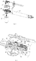
- the unlocking in this embodiment is mainly realized by the second driving member, the specific structure is as follows: as shown in FIGS. 2 to 4 , the second driving member includes a push block 54, the push block 54 is provided with a guide surface 541, the release torsion spring 40 includes a pin 401 extending radially, , the pin 401 in this embodiment extends out of a top of the housing, the guide surface 541 is provided on a side surface of the push block 54, the push block 54 is fixedly connected to a pull rod 52.
- the self-locking device and the clutch means in this embodiment share the same pull rod 52, as the pull rod 52 is pulled, the guide surface 541 on the push block 54 is in contact with the pin 401, such that the release torsion spring 40 is expanded outwardly, as the release torsion spring 40 is expanded outwardly, the resistance between the release torsion spring 40 and the second friction sleeve 42 is correspondingly reduced.
- the guide surface 541 is used to gradually push the release torsion spring 40, with this release method, the self-locking force can be gradually reduced, so that the self-locking force will not disappear immediately, thereby achieving the purpose of stepless adjustment.
- the operation sequence of the clutch means and the self-locking device is optimized.
- the pull rod 52 is provided with an oblong hole for adjustment
- the push block 54 is fixed to the oblong hole by a fastening screw
- the oblong hole is designed primarily for adjusting the initial position of the push block 54.
- There are two purposes for setting the initial position one is to make up for some actual assembly errors, so that the push block 54 can more precisely abut the release torsion spring 40, the second is that, as described herein, the operation sequence between the clutch means and the self-locking device can be adjusted.
- FIG. 2 the pull rod 52 is provided with an oblong hole for adjustment
- the push block 54 is fixed to the oblong hole by a fastening screw
- the oblong hole is designed primarily for adjusting the initial position of the push block 54.
- There are two purposes for setting the initial position one is to make up for some actual assembly errors, so that the push block 54 can more precisely abut the release tor
- the guide surface 541 of the push block 54 needs to be moved a certain stroke before it comes into contact with the pin 401 of the release torsion spring 40, this stroke can be understood as an idle stroke of the push block 54.
- this idle stroke the clutch means is in normal operation, the purpose of this configuration is that the coupling tooth sleeve 31 will be pivoted first, at the same time, when reset, the self-locking device first self-locks, and then the clutch means carries out power connection.
- the rotating speed of the rotating screw 20 will be reduced, so that the coupling tooth sleeve 31 and the drive worm 21 will not be damaged when the coupling tooth sleeve 31 is engaged with the drive worm 21, and the service life can be greatly prolonged.
- the pull rod 52 is provided with toothed bars 521, and the housing is provided with movable latches 522, which is connected with a spring.
- the pull rod 52 is pulled, the movable latches 522 are clamped into the toothed bars 521 one by one, and the pulling stroke of the pull rod 52 can be sensed by using the movable latches 522 at the position of the toothed bars 521.
- the structure of the self-locking device and the clutch means is not limited to the structure shown in this embodiment, in the case of the self-locking device, the self-locking device may include only a single third friction sleeve, the third friction sleeve rotates synchronously with the rotating screw, the release torsion spring is sleeved on the third friction sleeve. In the initial state, the release torsion spring clasps the third friction sleeve to generate resistance to the rotating screw, which is equivalent to the release torsion spring being a self-locking torsion spring. When the release torsion spring is pushed by the push block, the resistance of the release torsion spring to the third friction sleeve disappears.
- the clutch means can be implemented by a combination of other spline sleeves and splines. Embodiment II below also shows different embodiments of the self-locking device and the clutch means.
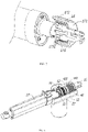
- the linear actuator in the present embodiment has a front puller 16 connected to an end portion of the inner tube 14, and a hand-rotating release device 17 is connected between the front puller 16 and the end portion of the inner tube 14.
- the power connection between the front puller 16 and the inner tube 14 can be cut off by the hand-rotating release device 17.
- the hand-rotating release device 17 includes a knob sleeve 171, a connecting sleeve seat 172 and a hand-rotating release torsion spring 173, the connecting sleeve seat 172 is fixedly connected with the inner pipe 14, the front puller 16 is fitted with the connecting sleeve seat 172, and the hand-rotating release torsion spring 173 is provided between the connecting sleeve seat 172 and the front puller 16.
- the hand-rotating release torsion spring 173 is sleeved outside the front puller 16, and the hand-rotating release torsion spring 173 also has a corresponding pin 1731, the pin 401 penetrates through a gap in the connecting sleeve seat 172 and abuts against the knob sleeve 171, and the knob sleeve 171 is used to pivot the hand-rotating release torsion spring 173 to contract radially or expand radially when rotated, thereby controlling the frictional resistance of the hand-rotating release torsion spring 173 to the front puller 16.
- the operation principle of this embodiment is similar to that of the embodiment I, mainly in that the specific structures of the self-locking device, the clutch means, the first driving member and the second driving member are different.
- the first friction sleeve 41 and the second friction sleeve 42 are axially arranged side by side, outer end faces of the first friction sleeve 41 and the second friction sleeve 42 are abutted against each other.
- the second friction sleeve 42 is sleeved outside the first friction sleeve 41, the outer end face of the first friction sleeve 41 abuts against the inner end face of the second friction sleeve 42.
- the first friction sleeve 41 rotates synchronously with the rotating screw 20, and the self-locking torsion spring 43 is also sleeved outside of the first friction sleeve 41, while the release torsion spring 40 is sleeved outside of the second friction sleeve 42.
- the working principle is similar to that of embodiment I, that is, the self-locking force of the self-locking torsion spring 43 mainly comes from the end friction force of the first friction sleeve 41 and the second friction sleeve 42.
- the first friction sleeve 41 in this embodiment is similar in structure in embodiment I and also includes a front shaft sleeve 411 and a rear shaft sleeve 412, a thrust bearing is arranged between the front shaft sleeve 411 and the rear shaft sleeve 412, the self-locking torsion spring 43 is sleeved outside the front shaft sleeve 411 and the rear shaft sleeve 412 at the same time, and the rear shaft sleeve 412 abuts against an inner end face of the second friction sleeve 42.
- the advantage of this self-locking device is that the installation space is smaller, mainly the axial space is smaller, which is beneficial to reduce the volume of the whole linear actuator.
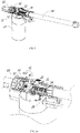
- the clutch means in the embodiment also includes a spline sleeve 34, the spline sleeve 34 is positioned between the rotating screw 20 and the coupling gear sleeve 31, the spline sleeve 34 rotates synchronously with the rotating screw 20, and torque transmission is mainly implemented by the flat position between the spline sleeve 34 and the rotating screw 20, while the coupling gear sleeve 31 and the drive worm 21 always keep synchronous rotation, and the first driving member mainly drives the clutch between the coupling gear sleeve 31 and the spline sleeve 34.
- the first driving member in this embodiment is slightly different from the embodiment I in that a shift block 55 is used, and the shift block 55 is rotationally connected with the pull rod 52. When the pull rod 52 is pulled, the shift block 55 pivots the axial movement of the coupling gear sleeve 31.
- the second driving member in this embodiment is directly integrated with the pull rod 52 as shown in FIG. 8 .
- the pull rod 52 is provided with a guide surface 541.
- the hand-rotating release device 17 is eliminated in this embodiment.
- the clutch means in this embodiment is the same as that in the embodiment I, the coupling gear sleeve itself is not subjected to the axial force from the rotating screw 20, and the axial force in this embodiment is transmitted as follows:
- the spline sleeve 34 and the first friction sleeve 41 are axially limited, therefore, the axial force is transmitted to the first friction sleeve 41, and a tail end face of the first friction sleeve 41 abuts against the inner end face of the second friction sleeve 42, so the axial force is transmitted to the second friction sleeve 42, and a tapered roller bearing 23 is arranged between the tail end face of the second friction sleeve 42 and the tail puller 10, so the axial force is finally transmitted to the tail puller 10 through the tapered roller bearing 23.
- the spline sleeve 34, the first friction sleeve 41 and the second friction sleeve 42 together constitute an axial limiting sleeve
- the rotating screw 20 transmits the axial force to the tail puller 10 through the axial limiting sleeve.
- the coupling gear sleeve in this embodiment will not be acted by the axial force all the time, so the first driving member is also very labor-saving when pivoting the coupling gear sleeve.
Landscapes
- Engineering & Computer Science (AREA)
- General Engineering & Computer Science (AREA)
- Mechanical Engineering (AREA)
- Power Engineering (AREA)
- Transmission Devices (AREA)
- Mechanical Operated Clutches (AREA)
Applications Claiming Priority (2)
| Application Number | Priority Date | Filing Date | Title |
|---|---|---|---|
| CN202010355867.4A CN111600432B (zh) | 2020-04-29 | 2020-04-29 | 一种离合顺畅的线性致动器 |
| PCT/CN2021/088231 WO2021218689A1 (zh) | 2020-04-29 | 2021-04-19 | 一种离合顺畅的线性致动器 |
Publications (4)
| Publication Number | Publication Date |
|---|---|
| EP4064530A1 true EP4064530A1 (de) | 2022-09-28 |
| EP4064530A4 EP4064530A4 (de) | 2023-05-24 |
| EP4064530C0 EP4064530C0 (de) | 2025-04-02 |
| EP4064530B1 EP4064530B1 (de) | 2025-04-02 |
Family
ID=72190949
Family Applications (1)
| Application Number | Title | Priority Date | Filing Date |
|---|---|---|---|
| EP21797611.7A Active EP4064530B1 (de) | 2020-04-29 | 2021-04-19 | Linearantrieb mit sanfter kupplung |
Country Status (4)
| Country | Link |
|---|---|
| US (1) | US12013016B2 (de) |
| EP (1) | EP4064530B1 (de) |
| CN (1) | CN111600432B (de) |
| WO (1) | WO2021218689A1 (de) |
Families Citing this family (4)
| Publication number | Priority date | Publication date | Assignee | Title |
|---|---|---|---|---|
| DE202019103358U1 (de) * | 2019-06-14 | 2020-09-15 | Dewertokin Gmbh | Linearantrieb |
| CN118959534A (zh) | 2020-04-29 | 2024-11-15 | 浙江捷昌线性驱动科技股份有限公司 | 一种操作方便的线性致动器 |
| CN111600432B (zh) | 2020-04-29 | 2025-07-08 | 浙江捷昌线性驱动科技股份有限公司 | 一种离合顺畅的线性致动器 |
| CN112713709A (zh) * | 2020-12-24 | 2021-04-27 | 浙江捷昌线性驱动科技股份有限公司 | 一种传动效率高的快速释放推杆 |
Family Cites Families (12)
| Publication number | Priority date | Publication date | Assignee | Title |
|---|---|---|---|---|
| TWI503496B (zh) * | 2013-05-23 | 2015-10-11 | Timotion Technology Co Ltd | 具有位置檢出機構的電動缸 |
| CN106246752B (zh) * | 2016-08-31 | 2018-12-28 | 浙江捷昌线性驱动科技股份有限公司 | 一种电动推杆 |
| CN206054568U (zh) * | 2016-08-31 | 2017-03-29 | 浙江捷昌线性驱动科技股份有限公司 | 一种电动推杆的离合装置 |
| CN207796016U (zh) * | 2017-10-26 | 2018-08-31 | 无锡市宏霸机电设备有限公司 | 一种电动推杆 |
| WO2019091997A1 (de) * | 2017-11-08 | 2019-05-16 | Dewertokin Gmbh | Elektromotorischer möbelantrieb mit klauenkupplung |
| CN108518465B (zh) * | 2018-04-19 | 2024-06-25 | 浙江捷昌线性驱动科技股份有限公司 | 一种线性致动器 |
| CN110103785B (zh) * | 2019-06-18 | 2024-01-16 | 湖北航嘉麦格纳座椅系统有限公司 | 一种车辆座椅的电动滑轨及滑轨总成 |
| CN111043184B (zh) * | 2019-12-18 | 2025-05-13 | 浙江捷昌线性驱动科技股份有限公司 | 一种线性致动器的刹车装置和线性致动器 |
| CN118959534A (zh) | 2020-04-29 | 2024-11-15 | 浙江捷昌线性驱动科技股份有限公司 | 一种操作方便的线性致动器 |
| CN111600432B (zh) * | 2020-04-29 | 2025-07-08 | 浙江捷昌线性驱动科技股份有限公司 | 一种离合顺畅的线性致动器 |
| CN212115058U (zh) * | 2020-04-29 | 2020-12-08 | 浙江捷昌线性驱动科技股份有限公司 | 一种离合顺畅的线性致动器 |
| CN112096819B (zh) * | 2020-08-20 | 2025-03-04 | 浙江捷昌线性驱动科技股份有限公司 | 一种带手旋释放装置的电动推杆 |
-
2020
- 2020-04-29 CN CN202010355867.4A patent/CN111600432B/zh active Active
-
2021
- 2021-04-19 US US17/783,649 patent/US12013016B2/en active Active
- 2021-04-19 WO PCT/CN2021/088231 patent/WO2021218689A1/zh not_active Ceased
- 2021-04-19 EP EP21797611.7A patent/EP4064530B1/de active Active
Also Published As
| Publication number | Publication date |
|---|---|
| WO2021218689A1 (zh) | 2021-11-04 |
| EP4064530C0 (de) | 2025-04-02 |
| EP4064530B1 (de) | 2025-04-02 |
| CN111600432B (zh) | 2025-07-08 |
| EP4064530A4 (de) | 2023-05-24 |
| US12013016B2 (en) | 2024-06-18 |
| CN111600432A (zh) | 2020-08-28 |
| US20230012355A1 (en) | 2023-01-12 |
Similar Documents
| Publication | Publication Date | Title |
|---|---|---|
| CN111577850B (zh) | 一种操作方便的线性致动器 | |
| US12013016B2 (en) | Linear actuator | |
| CN112096819B (zh) | 一种带手旋释放装置的电动推杆 | |
| US11015686B2 (en) | Electric linear actuator | |
| CN111810603A (zh) | 一种单向驱动的线性致动器 | |
| CN213393406U (zh) | 一种带手旋释放装置的电动推杆 | |
| CN212407484U (zh) | 一种操作方便的线性致动器 | |
| WO2021121342A1 (zh) | 一种线性致动器的刹车装置和线性致动器 | |
| WO2022214049A1 (zh) | 一种离合器执行机构及车辆 | |
| CN212115058U (zh) | 一种离合顺畅的线性致动器 | |
| CN219549516U (zh) | 具有快速释放功能的线性致动器 | |
| CN212564279U (zh) | 一种单向驱动的线性致动器 | |
| CA2930685A1 (en) | Actuator drive disconnection system | |
| CN111810551A (zh) | 一种发动机同步器机构 | |
| CN113513566B (zh) | 一种离合快速释放机构及线性致动器 | |
| CN218480080U (zh) | 一种离合组件、动力系统、转向控制装置及农机 | |
| WO2022228337A1 (zh) | 离合器执行机构及车辆 | |
| CN223483327U (zh) | 安全释放的线性致动器 | |
| CN214498752U (zh) | 开关门装置和烹饪设备 | |
| CN119641868A (zh) | 安全释放的线性致动器 | |
| CN221836629U (zh) | 一种轴向电动离合的电动绞盘 | |
| CN223246416U (zh) | 一种电动推杆 | |
| JPH09100889A (ja) | アクチュエータ |
Legal Events
| Date | Code | Title | Description |
|---|---|---|---|
| STAA | Information on the status of an ep patent application or granted ep patent |
Free format text: STATUS: THE INTERNATIONAL PUBLICATION HAS BEEN MADE |
|
| PUAI | Public reference made under article 153(3) epc to a published international application that has entered the european phase |
Free format text: ORIGINAL CODE: 0009012 |
|
| STAA | Information on the status of an ep patent application or granted ep patent |
Free format text: STATUS: REQUEST FOR EXAMINATION WAS MADE |
|
| 17P | Request for examination filed |
Effective date: 20220621 |
|
| AK | Designated contracting states |
Kind code of ref document: A1 Designated state(s): AL AT BE BG CH CY CZ DE DK EE ES FI FR GB GR HR HU IE IS IT LI LT LU LV MC MK MT NL NO PL PT RO RS SE SI SK SM TR |
|
| A4 | Supplementary search report drawn up and despatched |
Effective date: 20230426 |
|
| RIC1 | Information provided on ipc code assigned before grant |
Ipc: F16H 25/24 20060101ALI20230420BHEP Ipc: F16H 25/20 20060101ALI20230420BHEP Ipc: F16D 11/14 20060101ALI20230420BHEP Ipc: H02K 7/108 20060101ALI20230420BHEP Ipc: H02K 7/06 20060101ALI20230420BHEP Ipc: H02K 7/116 20060101AFI20230420BHEP |
|
| DAV | Request for validation of the european patent (deleted) | ||
| DAX | Request for extension of the european patent (deleted) | ||
| RIC1 | Information provided on ipc code assigned before grant |
Ipc: F16H 25/24 20060101ALI20241014BHEP Ipc: F16H 25/20 20060101ALI20241014BHEP Ipc: F16D 11/14 20060101ALI20241014BHEP Ipc: H02K 7/108 20060101ALI20241014BHEP Ipc: H02K 7/06 20060101ALI20241014BHEP Ipc: H02K 7/116 20060101AFI20241014BHEP |
|
| GRAP | Despatch of communication of intention to grant a patent |
Free format text: ORIGINAL CODE: EPIDOSNIGR1 |
|
| STAA | Information on the status of an ep patent application or granted ep patent |
Free format text: STATUS: GRANT OF PATENT IS INTENDED |
|
| INTG | Intention to grant announced |
Effective date: 20241204 |
|
| GRAS | Grant fee paid |
Free format text: ORIGINAL CODE: EPIDOSNIGR3 |
|
| GRAA | (expected) grant |
Free format text: ORIGINAL CODE: 0009210 |
|
| STAA | Information on the status of an ep patent application or granted ep patent |
Free format text: STATUS: THE PATENT HAS BEEN GRANTED |
|
| AK | Designated contracting states |
Kind code of ref document: B1 Designated state(s): AL AT BE BG CH CY CZ DE DK EE ES FI FR GB GR HR HU IE IS IT LI LT LU LV MC MK MT NL NO PL PT RO RS SE SI SK SM TR |
|
| REG | Reference to a national code |
Ref country code: GB Ref legal event code: FG4D |
|
| REG | Reference to a national code |
Ref country code: CH Ref legal event code: EP |
|
| REG | Reference to a national code |
Ref country code: IE Ref legal event code: FG4D |
|
| REG | Reference to a national code |
Ref country code: DE Ref legal event code: R096 Ref document number: 602021028617 Country of ref document: DE |
|
| U01 | Request for unitary effect filed |
Effective date: 20250423 |
|
| U07 | Unitary effect registered |
Designated state(s): AT BE BG DE DK EE FI FR IT LT LU LV MT NL PT RO SE SI Effective date: 20250430 |
|
| U20 | Renewal fee for the european patent with unitary effect paid |
Year of fee payment: 5 Effective date: 20250627 |
|
| PG25 | Lapsed in a contracting state [announced via postgrant information from national office to epo] |
Ref country code: ES Free format text: LAPSE BECAUSE OF FAILURE TO SUBMIT A TRANSLATION OF THE DESCRIPTION OR TO PAY THE FEE WITHIN THE PRESCRIBED TIME-LIMIT Effective date: 20250402 |
|
| PG25 | Lapsed in a contracting state [announced via postgrant information from national office to epo] |
Ref country code: NO Free format text: LAPSE BECAUSE OF FAILURE TO SUBMIT A TRANSLATION OF THE DESCRIPTION OR TO PAY THE FEE WITHIN THE PRESCRIBED TIME-LIMIT Effective date: 20250702 Ref country code: GR Free format text: LAPSE BECAUSE OF FAILURE TO SUBMIT A TRANSLATION OF THE DESCRIPTION OR TO PAY THE FEE WITHIN THE PRESCRIBED TIME-LIMIT Effective date: 20250703 |
|
| PG25 | Lapsed in a contracting state [announced via postgrant information from national office to epo] |
Ref country code: PL Free format text: LAPSE BECAUSE OF FAILURE TO SUBMIT A TRANSLATION OF THE DESCRIPTION OR TO PAY THE FEE WITHIN THE PRESCRIBED TIME-LIMIT Effective date: 20250402 |
|
| PG25 | Lapsed in a contracting state [announced via postgrant information from national office to epo] |
Ref country code: HR Free format text: LAPSE BECAUSE OF FAILURE TO SUBMIT A TRANSLATION OF THE DESCRIPTION OR TO PAY THE FEE WITHIN THE PRESCRIBED TIME-LIMIT Effective date: 20250402 |
|
| PG25 | Lapsed in a contracting state [announced via postgrant information from national office to epo] |
Ref country code: RS Free format text: LAPSE BECAUSE OF FAILURE TO SUBMIT A TRANSLATION OF THE DESCRIPTION OR TO PAY THE FEE WITHIN THE PRESCRIBED TIME-LIMIT Effective date: 20250702 |
|
| PG25 | Lapsed in a contracting state [announced via postgrant information from national office to epo] |
Ref country code: IS Free format text: LAPSE BECAUSE OF FAILURE TO SUBMIT A TRANSLATION OF THE DESCRIPTION OR TO PAY THE FEE WITHIN THE PRESCRIBED TIME-LIMIT Effective date: 20250802 |
|
| REG | Reference to a national code |
Ref country code: CH Ref legal event code: H13 Free format text: ST27 STATUS EVENT CODE: U-0-0-H10-H13 (AS PROVIDED BY THE NATIONAL OFFICE) Effective date: 20251125 |