EP4064306A1 - Disjoncteur, ensemble disjoncteur et contacteur - Google Patents
Disjoncteur, ensemble disjoncteur et contacteur Download PDFInfo
- Publication number
- EP4064306A1 EP4064306A1 EP20908135.5A EP20908135A EP4064306A1 EP 4064306 A1 EP4064306 A1 EP 4064306A1 EP 20908135 A EP20908135 A EP 20908135A EP 4064306 A1 EP4064306 A1 EP 4064306A1
- Authority
- EP
- European Patent Office
- Prior art keywords
- arc
- stationary contact
- piece
- breaker
- movable contact
- Prior art date
- Legal status (The legal status is an assumption and is not a legal conclusion. Google has not performed a legal analysis and makes no representation as to the accuracy of the status listed.)
- Pending
Links
- 230000003068 static effect Effects 0.000 abstract 8
- 238000010891 electric arc Methods 0.000 description 10
- 230000000712 assembly Effects 0.000 description 3
- 238000000429 assembly Methods 0.000 description 3
- 238000012423 maintenance Methods 0.000 description 3
- XEEYBQQBJWHFJM-UHFFFAOYSA-N Iron Chemical compound [Fe] XEEYBQQBJWHFJM-UHFFFAOYSA-N 0.000 description 2
- 238000009413 insulation Methods 0.000 description 2
- 238000002679 ablation Methods 0.000 description 1
- 238000007664 blowing Methods 0.000 description 1
- 229910052742 iron Inorganic materials 0.000 description 1
Images

Classifications
-
- H—ELECTRICITY
- H01—ELECTRIC ELEMENTS
- H01H—ELECTRIC SWITCHES; RELAYS; SELECTORS; EMERGENCY PROTECTIVE DEVICES
- H01H73/00—Protective overload circuit-breaking switches in which excess current opens the contacts by automatic release of mechanical energy stored by previous operation of a hand reset mechanism
- H01H73/02—Details
- H01H73/18—Means for extinguishing or suppressing arc
-
- H—ELECTRICITY
- H01—ELECTRIC ELEMENTS
- H01H—ELECTRIC SWITCHES; RELAYS; SELECTORS; EMERGENCY PROTECTIVE DEVICES
- H01H9/00—Details of switching devices, not covered by groups H01H1/00 - H01H7/00
- H01H9/30—Means for extinguishing or preventing arc between current-carrying parts
- H01H9/32—Insulating body insertable between contacts
-
- H—ELECTRICITY
- H01—ELECTRIC ELEMENTS
- H01H—ELECTRIC SWITCHES; RELAYS; SELECTORS; EMERGENCY PROTECTIVE DEVICES
- H01H1/00—Contacts
- H01H1/12—Contacts characterised by the manner in which co-operating contacts engage
- H01H1/14—Contacts characterised by the manner in which co-operating contacts engage by abutting
- H01H1/20—Bridging contacts
-
- H—ELECTRICITY
- H01—ELECTRIC ELEMENTS
- H01H—ELECTRIC SWITCHES; RELAYS; SELECTORS; EMERGENCY PROTECTIVE DEVICES
- H01H50/00—Details of electromagnetic relays
- H01H50/54—Contact arrangements
- H01H50/546—Contact arrangements for contactors having bridging contacts
-
- H—ELECTRICITY
- H01—ELECTRIC ELEMENTS
- H01H—ELECTRIC SWITCHES; RELAYS; SELECTORS; EMERGENCY PROTECTIVE DEVICES
- H01H9/00—Details of switching devices, not covered by groups H01H1/00 - H01H7/00
- H01H9/30—Means for extinguishing or preventing arc between current-carrying parts
- H01H9/34—Stationary parts for restricting or subdividing the arc, e.g. barrier plate
-
- H—ELECTRICITY
- H01—ELECTRIC ELEMENTS
- H01H—ELECTRIC SWITCHES; RELAYS; SELECTORS; EMERGENCY PROTECTIVE DEVICES
- H01H9/00—Details of switching devices, not covered by groups H01H1/00 - H01H7/00
- H01H9/30—Means for extinguishing or preventing arc between current-carrying parts
- H01H9/46—Means for extinguishing or preventing arc between current-carrying parts using arcing horns
Definitions
- the present disclosure relates to a breaker, in particular to a modular breaker.
- Breaker is an important component in a contactor and the like, the breaker includes a movable contact and a stationary contact, the movable contact moves to contact and disconnect with the stationary contact to control the on and off of a circuit.
- the existing breaker includes a contact group for multiple phases/poles in one housing, which is not conducive to the flexible design of the breaker as required and the damage of one contact will lead to the replacement of the whole breaker, thereby increasing the design and maintenance cost.
- the existing breaker has a relatively large volume.
- Embodiments of the present disclosure provides a breaker, which is used for controlling only one current path.
- the breaker includes: a contact assembly, an actuating member and a housing.
- the housing accommodates the contact assembly and the actuating member.
- the contact assembly includes: a first stationary contact, including a first stationary contact portion; a second stationary contact, including a second stationary contact portion; and a movable contact, including a first movable contact portion and a second movable contact portion which are respectively located at both ends of the movable contact.
- the actuating member is connected to the movable contact to actuate the movable contact in a first direction to move between an open position and a closed position.
- the first movable contact portion is spaced apart from the first stationary contact portion and the second movable contact portion is spaced apart from the second stationary contact portion to turn-off the one current path, and, at the closed position, the first movable contact portion is in contact with the first stationary contact portion and the second movable contact portion is in contact with the second stationary contact portion, to turn-on the one current path.
- the breaker only includes one movable contact and two stationary contacts, and the two stationary contacts are the first stationary contact and the second stationary contact respectively.
- the breaker further includes an arc extinguishing device, an arc running piece and an arc guiding piece.
- the arc extinguishing device includes a plurality of arc extinguishing grid sheets; the arc running piece is configured to guide an arc from the first stationary contact and the second stationary contact to the arc extinguishing device.
- the arc guiding piece is configured to guide an arc from the movable contact to the arc extinguishing device.
- the actuating member extends to an outside of the housing in the first direction.
- the first stationary contact and the second stationary contact respectively extend the outside of the housing in a second direction perpendicular to the first direction.
- the movable contact, the actuating member, the arc extinguishing device, the arc running piece and the arc guiding piece are completely accommodated in the housing.
- the plurality of arc extinguishing grid sheets are spaced apart from each other in the second direction, and extend into sheets in the first direction and a third direction perpendicular to the second direction.
- each of the first stationary contact and the second stationary contact includes a first parallel section, a second parallel section, and a contact curved section connecting the first parallel section and the second parallel section, the first parallel section extends in the second direction in the housing, and the second parallel section extends the outside of the housing in the second direction.
- the first and second stationary contact portions are respectively arranged on the first parallel section of the first stationary contact and the second stationary contact.
- the breaker further includes a first magnetic resistance piece and a second magnetic resistance piece.
- the first magnetic resistance piece is positioned between the first parallel section and the second parallel section of the first stationary contact in the first direction, and is closer to the first parallel section of the first stationary contact.
- the second magnetic resistance piece is positioned between the first parallel section and the second parallel section of the second stationary contact in the first direction, and is closer to the first parallel section of the second stationary contact.
- At least two arc extinguishing devices are provided and includes a first arc extinguishing device and a second arc extinguishing device.
- At least two arc running pieces are provided and includes a first arc running piece and a second arc running piece.
- the first arc running piece extends from a first arc running end portion of the first arc running piece arranged adjacent to the first stationary contact portion through the first arc extinguishing device to a second arc running end portion of the first running piece
- the second arc running piece extends from a third arc running end portion of the second arc running piece arranged adjacent to the second stationary contact portion through the second arc extinguishing device to a fourth arc running end portion of the second arc running piece.
- the arc guiding piece is an integral piece, and includes a first arc guiding section extending in the first direction and a second arc guiding section extending in the first direction, which are respectively located at both ends of the arc guiding piece.
- the first arc guiding section is arranged between the first arc extinguishing device and the movable contact in the second direction
- the second arc guiding section is arranged between the second arc extinguishing device and the movable contact in the second direction.
- the second arc running end portion of the first arc running piece and the first arc guiding section are arranged on opposite sides of the first arc extinguishing device in the second direction
- the fourth arc running end portion of the second arc running piece and the second arc guiding section are arranged on opposite sides of the first arc extinguishing device in the second direction.
- the breaker further includes: a first guide member and a second guide member, configured to guide a movement of the actuating member in the first direction, and the movable contact is arranged between the first guide member and the second guide member in the first direction.
- Embodiments of the present disclosure further provide a breaker assembly, which includes a plurality of the abovementioned breakers, actuating members of the plurality of breakers are connected with each other to move in linkage.
- Embodiments of the present disclosure further provide a contactor which includes the abovementioned breaker.
- Breaker can be used in a contactor to control the on and off of a current path.
- the contactor can be used for controlling the on and off of multiple current paths, for example, the on and off of three phase current paths.
- the breaker accommodates a plurality of contact assemblies (one contact assembly includes a stationary contact and a movable contact which correspond to each other and are used for controlling a current path) for controlling multiple phase current paths in a common housing, and for example, the plurality of contact assemblies are at least not completely spaced apart. Therefore, when a component in one of the contact assemblies is damaged, the whole breaker needs to be replaced, resulting in an increase in maintenance and replacement cost.
- there is an underutilized space in the housing of the breaker used for controlling the multiphase current so the structure of the breaker is not compact and the space utilization rate is low.
- At least one embodiment of the present disclosure provides a breaker, which is only used for controlling one current path.
- the breaker includes a contact assembly, an actuating member and a housing.
- the contact assembly includes a first stationary contact including a first stationary contact portion, a second stationary contact including a second stationary contact portion, and a movable contact having a first movable contact portion and a second movable contact portion located at both ends of the movable contact.
- the actuating member is connected to the movable contact to actuate the movable contact in a first direction to move between an open position and a closed position.
- the first movable contact portion is spaced apart from the first stationary contact portion and the second movable contact portion is spaced apart from the second stationary contact portion to turn-off the one current path.
- the first movable contact portion is in contact with the first stationary contact portion and the second movable contact portion is in contact with the second stationary contact portion to turn-on the one current path.
- the housing accommodates the contact assembly and the actuating member.
- the breaker is only used for controlling one current path.
- One single housing accommodates only one contact assembly, for example, two stationary contacts and one movable contact corresponding to the two stationary contacts. Therefore, upon a component being damaged, only one breaker for controlling only one current path needs to be replaced, and it is not necessary to replace a breaker used for controlling a plurality of current paths and having more components, thereby reducing the cost.
- the breaker is modularized, and the modular breaker can be flexibly combined as required to design a breaker assembly or a contactor.
- FIG. 1 shows a perspective view of a breaker according to the present disclosure, which shows the appearance of the breaker.
- FIG. 2 shows an internal plan view of a breaker according to an embodiment of the present disclosure.
- the breaker includes a housing 190, a contact assembly, an actuating member 130, arc extinguishing devices 140,140', arc running pieces 180,180', an arc guiding piece 150 and magnetic resistance pieces 160,160'.
- the housing 190 includes a first half shell 191 and a second half shell 192.
- the housing 190 is used to accommodate the contact assembly, the actuating member 130, the arc extinguishing devices 140,140', the arc running pieces 180,180', the arc guiding piece 150 and the magnetic resistance pieces 160,160'.
- FIG. 2 shows a plan view of the interior of the breaker, in which the second half shell 192 is removed to show the interior of the breaker. Referring to FIG.
- a first direction X up-down direction in the figure
- a second direction Y left-right direction in the figure
- a third direction Z direction perpendicular to the paper surface in the figure
- the contact assembly includes one first stationary contact 110, one second stationary contact 110' and one movable contact 120.
- the first stationary contact 110 includes a first stationary contact portion 114 (or a first stationary contact point)
- the second stationary contact 110' includes a second stationary contact portion 115 (or a second stationary contact point)
- the movable contact 120 includes a first movable contact portion 121 (or a first movable contact point) corresponding to the first stationary contact portion 114 and a second movable contact portion 122 (or a second movable contact point) corresponding to the second stationary contact portion 115.
- first stationary contact portion 114, the second stationary contact portion 115, the first movable contact portion 121 and the second movable contact portion 122 are all flat surfaces, but the present disclosure is not limited thereto.
- the first stationary contact portion 114 and the first movable contact portion 121 constitute a first group of contact portions
- the second stationary contact portion 115 and the second movable contact portion 122 constitute a second group of contact portions.
- the first stationary contact portion 114 and the first movable contact portion 121 face each other in the first direction X
- the second stationary contact portion 115 and the second movable contact portion 122 face each other in the first direction X.
- the first stationary contact 110 and the second stationary contact 110' are J-shaped, which generally extend in the second direction Y, and a part of each of the first stationary contact 110 and the second stationary contact 110' oppositely extends out of the housing 190 in the second direction Y, thereby allowing an external circuit to be electrically connected to the two stationary contacts 110,110'.
- the movable contact 120 extends in the second direction Y, and the first movable contact portion 121 and the second movable contact portion 122 are located at both ends of the movable contact 120.
- the movable contact 120 may include a movable contact body and an iron cap.
- the actuating member 130 passes through an opening in the middle of the movable contact 120 and is fixedly connected to the movable contact 120, and the actuating member 130 moves in the first direction X to actuate the movable contact 120 to move between an open position (referring to FIG. 2 , for example) and a closed position in the first direction X.
- a part of the actuating member 130 extends upward out of the housing 190 in the first direction X.
- the breaker also includes guide members 171,172, which include a first guide member 171 and a second guide member 172, which are spaced apart by a distance in the first direction X.
- the second guide member 172 is disposed at an opening of the housing 190, and the actuating member 130 extends out of the housing 190 through the opening.
- the first guide member 171 is disposed below the movable contact 120.
- the movable contact 120 is positioned between the first guide member 171 and the second guide member 172.
- the first movable contact portion 121 of the movable contact 120 is in contact with the first stationary contact portion 114 of the first stationary contact 110 to form electric connection
- the second movable contact portion 122 of the movable contact 120 is in contact with the second stationary contact portion 122 of the second stationary contact 110' to form electric connection, so as to turn-on a current path from the first stationary contact 110 to the second stationary contact 110' through the movable contact 120.
- the first movable contact portion 121 of the movable contact 120 is spaced apart from the first stationary contact portion 114 of the first stationary contact 110 for insulation, and the second movable contact portion 122 of the movable contact 120 is spaced apart from the second stationary contact portion 115 of the second stationary contact 110' for insulation.
- the current path from the first stationary contact 110 to the second stationary contact 110' through the movable contact 120 is turned-off.
- an electric arc may be generated between the first movable contact portion 121 and the first stationary contact portion 114 and the second movable contact portion 122 and the second stationary contact portion 115. Therefore, it is needed to provide a device for guiding and extinguishing the electric arc to guide the generated electric arc away from the stationary contacts 110,110' and the movable contacts 120 and extinguish the electric arc, so as to prevent the ablation and potential safety hazard of components such as the stationary contacts 110,110' and the movable contacts 120.
- the arc extinguishing devices 140,140', the arc guiding piece 150 and the arc running pieces 180,180' are provided to guide and extinguish the electric arc.
- the breaker becomes compact, for example, fully occupies the space volume, and the arc extinguishing performance is improved, for example, the arc dead time is reduced, the arc blowing performance is improved and the arc zero crossing times is reduced.
- the arc extinguishing devices 140,140' include a first arc extinguishing device 140 and a second arc extinguishing device 140', which are respectively used for the above-mentioned first group of contact portions and second group of contact portions.
- the arc running pieces 180,180' include a first arc running piece 180 and a second arc running piece 180', which are respectively used for the above-mentioned first group of contact portions and second group of contact portions.
- the magnetic resistance pieces 160,160' include a first magnetic resistance piece 160 and a second magnetic resistance piece 160', which are respectively used for the abovementioned first group of contact portions and second group of contact portions.
- the actuating member 130 and the arc guiding piece 150 are commonly used by the above-mentioned first group of contact portions and second group of contact portions.
- the first stationary contact 110 and the second stationary contact 110', the movable contact 120, the first arc running piece 180 and the second arc running pieces 180', the arc guiding piece 150, the first arc extinguishing device 140 and the second arc extinguishing device 140', and the first magnetic resistance piece 160 and the second magnetic resistance pieces 160' are in mirror arrangement with respect to the axis in the first direction X.
- the arc guiding piece 150, the movable contact 120 and the actuating member 130 are formed to be axisymmetric, but the present disclosure is not limited thereto.
- first stationary contact 110 and the second stationary contact 110' may be approximately the same, the first arc running piece 180 and the second arc running piece 180' may be approximately the same, and the first arc extinguishing device 140 and the second arc extinguishing device 140' may be approximately the same. Therefore, only the first stationary contact 110, the first arc running piece 180, the first arc extinguishing device 140 and the first magnetic resistance piece 160 will be described in detail below, and the descriptions of the first stationary contact 110, the first arc running piece 180, the first arc running piece 140 and the first magnetic resistance piece 160 can also be applied to the second stationary contact 110', the second arc running piece 180' and the second arc extinguishing device 140, respectively.
- the first arc extinguishing device 140 includes a plurality of arc extinguishing grid sheets 141.
- the first arc extinguishing device 140 includes six arc extinguishing grid sheets 141, which may be other numbers, such as less than five or more than seven.
- the arc extinguishing grid sheets 141 are spaced apart from each other in the second direction Y, and extend in sheet shapes in the first direction X and the third direction Z. Due to the orientation of the first arc extinguishing device 140, the volume of the breaker is reduced and the arrangement of various components of the breaker is more compact.
- the second arc extinguishing device 140' includes a plurality of arc extinguishing grid sheets arranged spaced apart from each other in the second direction Y.
- the first arc running piece 180 is used to guide the electric arc from the first stationary contact 110 to the first arc extinguishing device 140.
- the first arc running piece 180 has a rounded L- shape, and includes a first arm portion 181 having a first arc running end portion extending in the second direction Y, a second arm portion 182 having a second arc running end portion extending in the first direction X, and a curved connecting portion 183 connecting the first arm portion and the second arm portion.
- the first arc running end portion is disposed adjacent to the first stationary contact 110.
- the first arc running end portion is welded to a free end of the first stationary contact 110 close to the first stationary contact portion 114. Therefore, the arc guiding performance of the arc running piece can be enhanced.
- the first arc running piece 180 extends rightward and downward from the first arc running end portion in the first direction X and the second direction Y through the first arc extinguishing device 140 to the second arc running end portion. Because the first arc running piece 180 passes through the first arc extinguishing device 140, the first arc running piece 180 can guide the electric arc into the first arc extinguishing device 140 more quickly and effectively, thus improving the arc extinguishing performance of the breaker.
- the first arc running end portion is located on the first side (i.e., inside) of the first arc extinguishing device 140, and the second arc running end portion is located on the second side (i.e., outside) of the first arc extinguishing device 140, which is opposite to the first side.
- a notch is provided in the arc extinguishing grid sheet 141 of the first arc extinguishing device 140.
- the first arm portion 181 and the curved connecting portion 183 pass through the notches of the plurality of arc extinguishing grid sheets 141 of the first arc extinguishing device 140, so that a projection of the first arc-running grid 180 on the third direction Z at least partially overlaps with projections of the plurality of arc extinguishing grid sheets 141 in the third direction Z.
- the second arc running piece 180' is used to guide the electric arc from the second stationary contact 110' to the second arc extinguishing device 140', and includes a third arc running end portion and a fourth arc running end portion.
- the third arc running end portion is disposed adjacent to the second stationary contact 110'.
- the second arc running piece 180' extends leftwards and downwards from the third arc running end portion in the first direction X and the second direction Y through the second arc extinguishing device 140' to the fourth arc running end portion.
- the third arc running end portion is located on the third side (i.e., inside) of the second arc extinguishing device 140', and the fourth arc running end portion is located on the fourth side (i.e., outside) of the second arc extinguishing device 140', which is opposite to the third side.
- the second arc running piece 180' passes through the plurality of arc extinguishing grid sheets 141 of the second arc extinguishing device 140', so that a projection of the second arc running piece 180' on the third direction Z at least partially overlaps with projections of the plurality of arc extinguishing grid sheets 141 on the third direction Z. Therefore, the arc extinguishing performance of the breaker is improved.
- the arc guiding piece 150 is approximately M-shaped, and includes a first arc guiding section 151 and a second arc guiding section 152 both extending in the first direction X.
- the first arc guiding section 151 is arranged between the movable contact 120 and the first arc extinguishing device 140 in the second direction Y to guide the electric arc from the movable contact 120 to the first arc extinguishing device 140.
- the second arc guiding section 152 is arranged between the movable contact 120 and the second arc extinguishing device 140' in the second direction Y to guide the electric arc from the movable contact 120 to the second arc extinguishing device 140'.
- An opening is provided in the arc guiding piece 150, so that the movable contact 120 passes through the opening and moves.
- the arc guiding piece 150 is an integral piece.
- the first stationary contact 110 includes a first parallel section 111, a second parallel section 112, and a contact curved section 113 connecting the first parallel section 111 and the second parallel section 112.
- the first parallel section 111 extends in the second direction Y within the housing 190, and the second parallel section 112 extends out of the housing 190 in the second direction Y.
- the first stationary contact portion 114 is disposed on the first parallel section 111 of the first stationary contact 110.
- the second stationary contact 110' includes another first parallel section, another second parallel section, and another contact curved section connecting the first parallel section and the second parallel section.
- the second stationary contact portion 115 is disposed on the first parallel section of the second stationary contact 110'.
- the first magnetic resistance piece 160 is positioned between the first parallel section 111 and the second parallel section 112 of the first stationary contact 110 in the first direction X.
- the first magnetic resistance piece 160 extends parallel to the first parallel section 111 of the first stationary contact 110.
- the second magnetic resistance piece 160' is positioned between the first parallel section and the second parallel section of the second stationary contact 110' in the second direction Y.
- the second magnetic resistance piece 160' extends parallel to the first parallel section of the second stationary contact 110'.
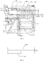
- FIG. 3 shows an enlarged view of a part of the dotted line box A-A in FIG. 2
- FIG. 4 shows an enlarged view of the first magnetic resistance piece 160 and the first parallel section 111 of the first stationary contact 110 in FIG. 2 .
- the shortest distance L1 between the movable contact 120 and the first arc guiding section 151 is approximately equal to the shortest distance L2 between the first arc guiding section 151 and the arc extinguishing grid sheet 141.
- the first movable contact portion 121, the first stationary contact portion 114, the second movable contact portion 120 and the second stationary contact portion 110' are all flat surfaces.
- the distance L3 between the first arc running piece 180 and the arc guiding piece 150 in the first direction X is the shortest. In the first direction X, the distance L3 between the first arc running piece 180 and the arc guiding piece 150 is approximately equal to the distance L4 between the first movable contact portion 121 and the first stationary contact portion 114 upon the movable contact 120 being at the open position.
- the first movable contact portion 121 is closer to the first stationary contact 110 than the arc guiding piece 150 in the first direction X, and the shortest distance L5 between the first movable contact portion 121 and the arc guiding piece 150 at the open position is approximately equal to the shortest distance L1 in the second direction Y between the movable contact 120 and the first arc guiding piece 151.
- the distance L6 between the first magnetic resistance piece 160 and the first parallel section 111 of the first stationary contact 110 in the first direction X is less than 0.5 mm.
- An embodiment according to the present disclosure further provides a breaker assembly, which includes a plurality of breakers, for example, the plurality of breakers as described above.
- the plurality of breakers are respectively used for controlling current paths of multiple phase currents, such as three phase current paths and two phase current paths.
- the actuating members 130 of the plurality of breakers are connected to each other to move in linkage.
- each of the breakers is only used for controlling one current path, it is possible to conveniently replace the breaker, combine the breakers to flexibly design the breaker assembly, and reduce the maintenance cost and modularize the breaker.
- An embodiment according to the present disclosure further provides a contactor, which includes a breaker, such as a plurality of breakers.
- a contactor which includes a breaker, such as a plurality of breakers.
- the breaker is the abovementioned breaker.
Applications Claiming Priority (2)
| Application Number | Priority Date | Filing Date | Title |
|---|---|---|---|
| CN201922351226.7U CN210956485U (zh) | 2019-12-24 | 2019-12-24 | 分断器、分断器组件和接触器 |
| PCT/CN2020/139013 WO2021129738A1 (fr) | 2019-12-24 | 2020-12-24 | Disjoncteur, ensemble disjoncteur et contacteur |
Publications (2)
| Publication Number | Publication Date |
|---|---|
| EP4064306A1 true EP4064306A1 (fr) | 2022-09-28 |
| EP4064306A4 EP4064306A4 (fr) | 2023-12-13 |
Family
ID=71395961
Family Applications (1)
| Application Number | Title | Priority Date | Filing Date |
|---|---|---|---|
| EP20908135.5A Pending EP4064306A4 (fr) | 2019-12-24 | 2020-12-24 | Disjoncteur, ensemble disjoncteur et contacteur |
Country Status (4)
| Country | Link |
|---|---|
| US (1) | US20230026399A1 (fr) |
| EP (1) | EP4064306A4 (fr) |
| CN (1) | CN210956485U (fr) |
| WO (1) | WO2021129738A1 (fr) |
Families Citing this family (5)
| Publication number | Priority date | Publication date | Assignee | Title |
|---|---|---|---|---|
| CN210956485U (zh) * | 2019-12-24 | 2020-07-07 | 施耐德电器工业公司 | 分断器、分断器组件和接触器 |
| CN210897140U (zh) * | 2019-12-24 | 2020-06-30 | 施耐德电器工业公司 | 分断器和接触器 |
| CN113948324A (zh) | 2020-07-16 | 2022-01-18 | 施耐德电器工业公司 | 一种具有支架导向组件的模块化分断单元和接触器 |
| CN215988605U (zh) * | 2021-05-28 | 2022-03-08 | 施耐德电器工业公司 | 偏转件、分断模块和接触器 |
| CN116387111B (zh) * | 2023-06-01 | 2023-11-14 | 广东南冠电气有限公司 | 智能量测断路器 |
Family Cites Families (18)
| Publication number | Priority date | Publication date | Assignee | Title |
|---|---|---|---|---|
| JP3411206B2 (ja) * | 1997-12-26 | 2003-05-26 | 三菱電機株式会社 | 接点開閉機器の消弧装置 |
| US6064024A (en) * | 1999-06-25 | 2000-05-16 | Eaton Corporation | Magnetic enhanced arc extinguisher for switching assemblies having rotatable permanent magnets in housings mounted to fixed contacts |
| CN2415444Y (zh) * | 2000-01-08 | 2001-01-17 | 上海电器科学研究所 | 交流接触器触头灭弧装置 |
| DE10356271B4 (de) * | 2003-11-28 | 2008-02-14 | Siemens Ag | Schaltgerät |
| US7551050B2 (en) * | 2006-09-22 | 2009-06-23 | Rockwell Automation Technologies, Inc. | Contactor assembly with arc steering system |
| WO2011147458A1 (fr) * | 2010-05-28 | 2011-12-01 | Abb Research Ltd | Commutateur pour courant continu |
| KR101386582B1 (ko) * | 2010-06-04 | 2014-04-18 | 엘에스산전 주식회사 | 배선용 차단기 |
| EP2463878A1 (fr) * | 2010-12-07 | 2012-06-13 | Eaton Industries GmbH | Commutateur doté d'une chambre d'extinction |
| FR2999791B1 (fr) * | 2012-12-18 | 2015-01-02 | Schneider Electric Ind Sas | Dispositif modulaire de commutation electrique comportant au moins un bloc de coupure unipolaire et ensemble de commutation comportant de tels dispositifs |
| FR3003392B1 (fr) * | 2013-03-15 | 2016-07-22 | Schneider Electric Ind Sas | Bloc unitaire de commutation et dispositif de commutation comportant au moins un tel bloc |
| CN103311063B (zh) * | 2013-06-05 | 2016-03-02 | 常熟开关制造有限公司(原常熟开关厂) | 一种断路器触头结构 |
| EP2989653B1 (fr) * | 2013-09-13 | 2017-05-31 | Siemens Aktiengesellschaft | Contacteur avec un mécanisme de déclenchement amélioré en cas de court-circuit |
| FR3030870B1 (fr) * | 2014-12-19 | 2018-01-05 | Schneider Electric Industries Sas | Dispositif de commutation electrique muni de moyens de signalisation de la presence de blocs auxiliaires |
| FR3050566B1 (fr) * | 2016-04-21 | 2019-08-30 | Schneider Electric Industries Sas | Disjoncteur a coupure dans l'air presentant une chambre de coupure d'arc electrique amelioree |
| FR3060193B1 (fr) * | 2016-12-08 | 2019-05-17 | Schneider Electric Industries Sas | Element amovible de coupure pour un appareil de coupure electrique et appareil de coupure d'un courant electrique comprenant un tel element amovible |
| CN109285704A (zh) * | 2018-10-16 | 2019-01-29 | 浙江正泰电器股份有限公司 | 双断点触头的灭弧结构 |
| CN210956485U (zh) * | 2019-12-24 | 2020-07-07 | 施耐德电器工业公司 | 分断器、分断器组件和接触器 |
| CN210897140U (zh) * | 2019-12-24 | 2020-06-30 | 施耐德电器工业公司 | 分断器和接触器 |
-
2019
- 2019-12-24 CN CN201922351226.7U patent/CN210956485U/zh active Active
-
2020
- 2020-12-24 WO PCT/CN2020/139013 patent/WO2021129738A1/fr unknown
- 2020-12-24 US US17/788,004 patent/US20230026399A1/en active Pending
- 2020-12-24 EP EP20908135.5A patent/EP4064306A4/fr active Pending
Also Published As
| Publication number | Publication date |
|---|---|
| EP4064306A4 (fr) | 2023-12-13 |
| WO2021129738A1 (fr) | 2021-07-01 |
| US20230026399A1 (en) | 2023-01-26 |
| CN210956485U (zh) | 2020-07-07 |
Similar Documents
| Publication | Publication Date | Title |
|---|---|---|
| EP4064306A1 (fr) | Disjoncteur, ensemble disjoncteur et contacteur | |
| EP4064311A1 (fr) | Disjoncteur et contacteur | |
| JP6103489B2 (ja) | 直流開閉器の消弧機構、および当該消弧機構を有する直流開閉器並びに直流遮断器 | |
| MX2015003013A (es) | Tobogan de arco de corriente continua sencillo, y aparato interruptor electrico de corriente, continua, bi-direccional que lo emplea. | |
| KR940006164A (ko) | 개폐기 | |
| CN105679610A (zh) | 带辅助触点的高压密封直流接触器 | |
| US2898427A (en) | Arc extinguishing means | |
| US3895199A (en) | Multi-pole vacuum switching apparatus | |
| CN220172050U (zh) | 灭弧室和断路器 | |
| US2874245A (en) | Circuit breaker | |
| CN102623252B (zh) | 具有双稳态限流触头的电容接触器 | |
| CN107230586A (zh) | 一种小型断路器改良结构 | |
| EP3385974A1 (fr) | Disjoncteur différentiel | |
| JP6044927B2 (ja) | 直流開閉器および直流遮断器 | |
| JP6098078B2 (ja) | 直流開閉器および直流遮断器 | |
| WO2014137642A2 (fr) | Appareil de commutation électrique et ensemble liaison pour celui-ci | |
| CN202307611U (zh) | 电气装置的电弧室 | |
| CN217768254U (zh) | 断路器隔离结构和断路器 | |
| JP7076635B2 (ja) | 回路遮断器 | |
| WO2017141197A1 (fr) | Interrupteur électrique incorporant un système de sectionnement d'arc | |
| KR100443943B1 (ko) | 아크 자기구동방식의 차단기 및 개폐기용 소호부 구조체 | |
| CN104040672A (zh) | 塑壳断路器 | |
| KR200241477Y1 (ko) | 배선용차단기의소호장치 | |
| CN115831641A (zh) | 一种无极性磁场驱动电弧结构 | |
| JPH06283090A (ja) | 回路遮断器 |
Legal Events
| Date | Code | Title | Description |
|---|---|---|---|
| STAA | Information on the status of an ep patent application or granted ep patent |
Free format text: STATUS: THE INTERNATIONAL PUBLICATION HAS BEEN MADE |
|
| PUAI | Public reference made under article 153(3) epc to a published international application that has entered the european phase |
Free format text: ORIGINAL CODE: 0009012 |
|
| STAA | Information on the status of an ep patent application or granted ep patent |
Free format text: STATUS: REQUEST FOR EXAMINATION WAS MADE |
|
| 17P | Request for examination filed |
Effective date: 20220624 |
|
| AK | Designated contracting states |
Kind code of ref document: A1 Designated state(s): AL AT BE BG CH CY CZ DE DK EE ES FI FR GB GR HR HU IE IS IT LI LT LU LV MC MK MT NL NO PL PT RO RS SE SI SK SM TR |
|
| DAV | Request for validation of the european patent (deleted) | ||
| DAX | Request for extension of the european patent (deleted) | ||
| REG | Reference to a national code |
Ref country code: DE Ref legal event code: R079 Free format text: PREVIOUS MAIN CLASS: H01H0009020000 Ipc: H01H0050540000 |
|
| A4 | Supplementary search report drawn up and despatched |
Effective date: 20231110 |
|
| RIC1 | Information provided on ipc code assigned before grant |
Ipc: H01H 50/54 20060101AFI20231106BHEP |