EP4064237A1 - Harzbehälter und überwachungsvorrichtung - Google Patents
Harzbehälter und überwachungsvorrichtung Download PDFInfo
- Publication number
- EP4064237A1 EP4064237A1 EP20888823.0A EP20888823A EP4064237A1 EP 4064237 A1 EP4064237 A1 EP 4064237A1 EP 20888823 A EP20888823 A EP 20888823A EP 4064237 A1 EP4064237 A1 EP 4064237A1
- Authority
- EP
- European Patent Office
- Prior art keywords
- lid
- signal
- reflector
- communication unit
- resin container
- Prior art date
- Legal status (The legal status is an assumption and is not a legal conclusion. Google has not performed a legal analysis and makes no representation as to the accuracy of the status listed.)
- Withdrawn
Links
Images


Classifications
-
- G—PHYSICS
- G01—MEASURING; TESTING
- G01S—RADIO DIRECTION-FINDING; RADIO NAVIGATION; DETERMINING DISTANCE OR VELOCITY BY USE OF RADIO WAVES; LOCATING OR PRESENCE-DETECTING BY USE OF THE REFLECTION OR RERADIATION OF RADIO WAVES; ANALOGOUS ARRANGEMENTS USING OTHER WAVES
- G01S13/00—Systems using the reflection or reradiation of radio waves, e.g. radar systems; Analogous systems using reflection or reradiation of waves whose nature or wavelength is irrelevant or unspecified
- G01S13/02—Systems using reflection of radio waves, e.g. primary radar systems; Analogous systems
- G01S13/04—Systems determining presence of a target
-
- H—ELECTRICITY
- H01—ELECTRIC ELEMENTS
- H01Q—ANTENNAS, i.e. RADIO AERIALS
- H01Q19/00—Combinations of primary active antenna elements and units with secondary devices, e.g. with quasi-optical devices, for giving the antenna a desired directional characteristic
- H01Q19/10—Combinations of primary active antenna elements and units with secondary devices, e.g. with quasi-optical devices, for giving the antenna a desired directional characteristic using reflecting surfaces
-
- G—PHYSICS
- G08—SIGNALLING
- G08B—SIGNALLING SYSTEMS, e.g. PERSONAL CALLING SYSTEMS; ORDER TELEGRAPHS; ALARM SYSTEMS
- G08B13/00—Burglar, theft or intruder alarms
- G08B13/02—Mechanical actuation
- G08B13/08—Mechanical actuation by opening, e.g. of door, of window, of drawer, of shutter, of curtain, of blind
-
- H—ELECTRICITY
- H01—ELECTRIC ELEMENTS
- H01Q—ANTENNAS, i.e. RADIO AERIALS
- H01Q1/00—Details of, or arrangements associated with, antennas
- H01Q1/04—Adaptation for subterranean or subaqueous use
-
- H—ELECTRICITY
- H01—ELECTRIC ELEMENTS
- H01Q—ANTENNAS, i.e. RADIO AERIALS
- H01Q19/00—Combinations of primary active antenna elements and units with secondary devices, e.g. with quasi-optical devices, for giving the antenna a desired directional characteristic
- H01Q19/10—Combinations of primary active antenna elements and units with secondary devices, e.g. with quasi-optical devices, for giving the antenna a desired directional characteristic using reflecting surfaces
- H01Q19/12—Combinations of primary active antenna elements and units with secondary devices, e.g. with quasi-optical devices, for giving the antenna a desired directional characteristic using reflecting surfaces wherein the surfaces are concave
-
- G—PHYSICS
- G01—MEASURING; TESTING
- G01S—RADIO DIRECTION-FINDING; RADIO NAVIGATION; DETERMINING DISTANCE OR VELOCITY BY USE OF RADIO WAVES; LOCATING OR PRESENCE-DETECTING BY USE OF THE REFLECTION OR RERADIATION OF RADIO WAVES; ANALOGOUS ARRANGEMENTS USING OTHER WAVES
- G01S13/00—Systems using the reflection or reradiation of radio waves, e.g. radar systems; Analogous systems using reflection or reradiation of waves whose nature or wavelength is irrelevant or unspecified
- G01S13/003—Bistatic radar systems; Multistatic radar systems
-
- G—PHYSICS
- G01—MEASURING; TESTING
- G01S—RADIO DIRECTION-FINDING; RADIO NAVIGATION; DETERMINING DISTANCE OR VELOCITY BY USE OF RADIO WAVES; LOCATING OR PRESENCE-DETECTING BY USE OF THE REFLECTION OR RERADIATION OF RADIO WAVES; ANALOGOUS ARRANGEMENTS USING OTHER WAVES
- G01S13/00—Systems using the reflection or reradiation of radio waves, e.g. radar systems; Analogous systems using reflection or reradiation of waves whose nature or wavelength is irrelevant or unspecified
- G01S13/88—Radar or analogous systems specially adapted for specific applications
-
- G—PHYSICS
- G01—MEASURING; TESTING
- G01S—RADIO DIRECTION-FINDING; RADIO NAVIGATION; DETERMINING DISTANCE OR VELOCITY BY USE OF RADIO WAVES; LOCATING OR PRESENCE-DETECTING BY USE OF THE REFLECTION OR RERADIATION OF RADIO WAVES; ANALOGOUS ARRANGEMENTS USING OTHER WAVES
- G01S7/00—Details of systems according to groups G01S13/00, G01S15/00, G01S17/00
- G01S7/003—Transmission of data between radar, sonar or lidar systems and remote stations
- G01S7/006—Transmission of data between radar, sonar or lidar systems and remote stations using shared front-end circuitry, e.g. antennas
-
- G—PHYSICS
- G08—SIGNALLING
- G08B—SIGNALLING SYSTEMS, e.g. PERSONAL CALLING SYSTEMS; ORDER TELEGRAPHS; ALARM SYSTEMS
- G08B25/00—Alarm systems in which the location of the alarm condition is signalled to a central station, e.g. fire or police telegraphic systems
- G08B25/01—Alarm systems in which the location of the alarm condition is signalled to a central station, e.g. fire or police telegraphic systems characterised by the transmission medium
- G08B25/08—Alarm systems in which the location of the alarm condition is signalled to a central station, e.g. fire or police telegraphic systems characterised by the transmission medium using communication transmission lines
-
- G—PHYSICS
- G08—SIGNALLING
- G08B—SIGNALLING SYSTEMS, e.g. PERSONAL CALLING SYSTEMS; ORDER TELEGRAPHS; ALARM SYSTEMS
- G08B25/00—Alarm systems in which the location of the alarm condition is signalled to a central station, e.g. fire or police telegraphic systems
- G08B25/01—Alarm systems in which the location of the alarm condition is signalled to a central station, e.g. fire or police telegraphic systems characterised by the transmission medium
- G08B25/10—Alarm systems in which the location of the alarm condition is signalled to a central station, e.g. fire or police telegraphic systems characterised by the transmission medium using wireless transmission systems
Definitions
- the present invention relates to a resin container that houses cables, and a monitoring device.
- wireless communication devices When wireless communication devices are installed in underground spaces, physical contact is more likely to occur to the wireless communication devices than when the wireless communication devices are installed above (spatially above) buildings and other structures. This increases the possibility of wireless communication devices being stolen, destroyed, or otherwise damaged.
- an object of the present invention to provide a resin container and a monitoring device capable of monitoring the state of a lid and reducing or preventing theft, destruction, or other damage to the contents based on the monitoring results.
- a resin container is directed to a resin container that accommodates a cable, and the resin container includes: a container body including an opening which is open upward; a lid that closes the opening; and at least one device that detects a change from an initial installation state of the resin container by an optical or electrical means.
- the device includes a wireless communication device that transmits a detection result to outside
- the resin container further includes a monitoring device which is installed inside or outside of the resin container, and examines a change in a state of the resin container based on the detection result.
- the device includes one or more first reflector(s) provided at a predetermined location inside of the lid.
- the first reflector is provided in a position and at an angle such that, when a signal is transmitted from a second communication unit of the wireless communication device with the lid closing the opening, the first reflector reflects the signal, and the signal is received by the second communication unit.
- the first reflector is provided in a position and at an angle such that, when signals are transmitted from the second communication unit in two or more different directions with the lid closing the opening, the first reflector reflects all signals transmitted from the second communication unit, and the all signals are received by the second communication unit.
- the resin container includes one or more second reflector(s) provided at a predetermined location inside of the container body, and the first reflector and the second reflector are each provided in a position and at an angle such that, when a signal is transmitted from the second communication unit with the lid closing the opening, the first reflector and the second reflector each reflect the signal, and the signal is received by the second communication unit.
- first reflector and the second reflector are each provided in a position and at an angle such that, when signals are transmitted from the second communication unit in two or more different directions with the lid closing the opening, the first reflector and the second reflector reflect all signals transmitted from the second communication unit, and the all signals are received by the second communication unit.
- a monitoring device is directed to a monitoring device that monitors a state of the lid of the resin container, and the monitoring device includes: a determinator that determines whether the state of the lid has changed beyond a certain level based on a signal received by the second communication unit; and an error signal generator that, when the determinator determines that the state of the lid has changed beyond a certain level, generates an error signal.
- the determinator determines whether the state of the lid has changed beyond a certain level based on an electric field strength of the signal received by the second communication unit.
- the monitoring device includes a memory unit that stores one or more pattern(s) indicating a change in the state of the lid, and the determinator compares a pattern of an electric field strength of the signal with a pattern stored in the memory unit to determine whether the state of the lid has changed beyond a certain level based on a comparison result.
- the monitoring device includes a memory unit that stores one or more pattern(s) indicating a change in the state of the lid; and an identification unit that identifies the change in the state of the lid, in which the identification unit compares a pattern of an electric field strength of the signal with a pattern stored in the memory unit to determine whether the state of the lid has changed beyond a certain level based on a comparison result.
- a resin container and a monitoring device capable of monitoring the state of the lid and reducing or preventing theft, destruction, or other damage to the contents based on the monitoring results.
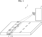
- FIG. 1 shows an overview of a monitoring system 1 according to the present invention.
- the monitoring system 1 is intended to detect theft, destruction, or other damage to a wireless communication device 2 located inside a resin container 5.
- the monitoring system 1 includes the wireless communication device 2, a management device 3, and an error reporting device 4.
- the wireless communication device 2 sends and receives communication radio waves for wirelessly communicating with wireless communication apparatuses.
- the wireless communication device 2 is, for example, a base station device for 5G (5th generation mobile communication system). However, the wireless communication device 2 is not limited to base station devices for 5G.
- the wireless communication apparatuses are, for example, mobile phones, smartphones, tablets, etc.
- the management device 3 is connected to the wireless communication device 2 by wired or wireless means.
- the management device 3 receives an error signal from the wireless communication device 2, and sends an error reporting signal to the error reporting device 4 to report the error.
- the error reporting device 4 receives the error reporting signal from the management device 3, and reports the error of wireless communication device 2.
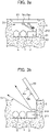
- FIGS. 2a and 2b show an overview of the wireless communication device 2 and the resin container 5 according to the first embodiment.
- the wireless communication device 2 functioning as a monitoring device is installed inside the resin container 5.
- the resin container 5 is described as one in which a portion of a lid 53 is exposed on the surface and a container body 52 is buried in the ground.
- the resin container 5 is a container for cables such as a communication line 6 and a power line 7.
- the power line 7 is connected to the wireless communication device 2 and supplies power to the wireless communication device 2.
- the resin container 5 has an opening 51, the container body 52, the lid 53, and a first reflector 54a.
- the container body 52 is buried underground.
- the container body 52 has the opening 51 that opens upward.
- the lid 53 closes the opening 51 and seals the container body 52.
- the lid 53 is made of a material that transmits radio waves sent and received between the wireless communication device 2 and the wireless communication apparatus.
- the first reflector 54a is provided at a predetermined location inside the lid 53 (the side facing the opening 51 when the container body 52 is sealed).
- the first reflector 54a reflects a signal transmitted from a second communication unit 212.
- the wireless communication device 2 is provided inside the container body 52.
- the wireless communication device 2 has a mechanism for detecting changes from the initial installation state of the resin container 5.
- the wireless communication device 2 transmits the detection results to the outside.
- the wireless communication device 2 is installed inside or outside of the resin container 5.
- the wireless communication device 2 functions as a monitoring device that examines changes in the state of the resin container 5 based on the detection results.
- the first reflector 54a and the wireless communication device 2 each function as a mechanism for detecting changes from the initial installation state of the resin container 5 by an optical or electrical means.
- the wireless communication device 2 includes a first communication unit 211 and a second communication unit 212.
- the first communication unit 211 communicates with wireless communication apparatuses.
- the second communication unit 212 sends and receives signals to monitor the status of the lid 53.
- the communication line 6 includes, for example, an optical fiber.
- the communication line 6 may include a coaxial cable.
- the wireless communication device 2 and a switching station (not shown) are connected by the communication line 6.
- the first communication unit 211 performs a prescribed communication with the switching station via the communication line 6.
- the wireless communication apparatus can communicate and talk with other wireless communication apparatuses by communicating with the first communication unit 211.
- the management device 3 may be directly connected to the wireless communication device 2 by wire (the communication line 6) or wirelessly. Alternatively, the management device 3 may be connected to the wireless communication device 2 via the internet through a gateway (not shown) connected to a switching device.
- the wireless communication device 2 transmits the information obtained from the second communication unit 212 to the management device 3.
- the management device 3 monitors (determines) the state of the lid 53 (whether the lid 53 is open or not) based on the result of the communication by the second communication unit 212.
- the management device 3 monitors (determines) the state of the lid 53 (whether the lid 53 is displaced or not) based on the result of the communication by the second communication unit 212.
- the first reflector 54a is provided, for example, in the position and at the angle shown in FIG. 2a .
- the first reflector 54a reflects the signal.
- the signal is received by the second communication unit 212.
- the first reflector 54a reflects a part of or the entire signal. This reflected signal is considered to be reflected in a different direction from the reflected signal with the lid 53 fully closed. Then, depending on the angle of the reflected signal, the second communication unit 212 either does not receive the reflected signal or receives a reflected signal of weak strength (in electric field strength).
- the second communication unit 212 transmits signals at a predetermined timing.
- the wireless communication device 2 transmits the information obtained by the second communication unit 212 to the management device 3.
- the information obtained by the second communication unit 212 includes, for example, information such as the presence or absence of a reflected signal, the strength of the reflected signal, and the time required to receive the reflected signal after transmitting the signal.
- the management device 3 monitors the status of the lid 53 based on the information obtained from the second communication unit 212.
- a unique ID is assigned to the wireless communication device 2.
- the wireless communication device 2 sends this unique ID together with the information obtained by the second communication unit 212 to the management device 3.
- the management device 3 can identify the location where the wireless communication device 2 is located based on the unique ID.
- the management device 3 can determine that the lid 53 is not closing the opening 51. Furthermore, when the strength of the reflected signal is found to be weaker or stronger than normal based on the information obtained by the second communication unit 212, the management device 3 can determine that the lid 53 is displaced, or flexing inward. Furthermore, when it is found that the time required to receive the reflected signal is shorter or longer than usual based on the information obtained by the second communication unit 212, the management device 3 can determine that the lid 53 is displaced, etc.
- the monitoring system 1 can monitor the state of the lid 53, and detect whether the lid 53 is in an erroneous state (e.g., the lid 53 is open) based on the signal reflected by the first reflector 54a.
- the monitoring system 1 can also communicate, to the monitoring staff, information relating to the location where the wireless communication device 2 is located, as identified by the management device 3. This allows the staff to check the status of the lid 53 in which an error has been detected. Furthermore, the monitoring system 1 can also activate an alarm device located near the wireless communication device 2. Therefore, the monitoring system 1 can quickly determine the status of theft, destruction, or other damage to the wireless communication device 2 located in the resin container 5 covered by the lid 53 in which an error has been detected. Furthermore, the monitoring system 1 can also activate an alarm device located near the wireless communication device 2. This can prevent theft or destruction of the wireless communication device 2 located in the resin container 5 covered by the lid 53 for which an error has been detected.
- a resin container 5 according to the second embodiment includes a first reflector 54b in addition to the first reflector 54a. This point differs mainly from the first embodiment. In terms of other configurations, the second embodiment has the same configuration as the wireless communication device and resin container of the first embodiment shown in FIG. 2 .
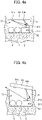
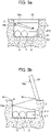
- FIG. 3a and 3b show an overview of a wireless communication device and a resin container according to the second embodiment.
- the resin container 5 includes first reflectors 54a and 54b.
- the first reflectors 54a and 54b include a plurality of reflectors.
- the plurality of reflectors are located at predetermined locations inside the lid 53.
- the first reflectors 54a and 54b are, for example, provided in the positions and at the angles as shown in FIG. 3a .
- the first reflectors 54a and 54b reflect all signals transmitted from the second communication unit 212, and those signals are received by the second communication unit 212.
- the first reflector 54a is disposed in the vicinity of one end of the lid 53.
- the first reflector 54b is disposed in the vicinity of the other end of the lid 53.
- the monitoring system 1 can monitor the state of the lid 53 (whether the lid 53 is open wide, the side on which the lid 53 is open), and detect an error in the lid 53 based on the presence/absence or strength of the reflected signals from the respective first reflectors 54a and 54b which are provided at the different locations of the lid 53.
- the monitoring system 1 can also communicate to the monitoring staff information on the location where the wireless communication device 2 is located, as identified by the management device 3. This allows the staff to check the status of the lid 53 in which an error has been detected. Furthermore, the monitoring system 1 can also activate an alarm device located near the wireless communication device 2. Therefore, the monitoring system 1 can quickly determine the status of theft, destruction, or other damage to the wireless communication device 2 located in the resin container 5 covered by the lid 53 in which an error has been detected. Furthermore, the monitoring system 1 can also activate an alarm device located near the wireless communication device 2. This can prevent theft or destruction of the wireless communication device 2 located in the resin container 5 covered by the lid 53 in which the error has been detected.
- a resin container 5 according to the third embodiment includes a second reflector 54c in addition to the first reflector 54a.
- the third embodiment differs from the first embodiment in this respect. In other configurations, the third embodiment is identical to the first embodiment.
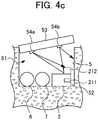
- FIGS. 5a and 5b show an overview of a wireless communication device and a resin container according to the third embodiment.
- the resin container 5 includes a first reflector 54a and a second reflector 54c.
- the first reflector 54a is disposed at a predetermined location inside of the lid 53.
- the second reflector 54c is disposed at a predetermined location inside of the container body 52.
- the first reflector 54a and the second reflector 54c are, for example, provided in the positions and at the angles as shown in FIG. 5a .
- the first reflector 54a and the second reflector 54c reflect the signal, and the signal is received by the second communication unit 212.
- the transmitted signal is reflected by the second reflector 54c located on the container body 52, then reflected by the first reflector 54a located on the lid 53, and received by the second communication unit 212.
- the signal transmitted from the second communication unit 212 may be reflected by the first reflector 54a located on the lid 53, then reflected by the second reflector 54c located on the container body 52, and received by the second communication unit 212.
- the monitoring system 1 of the third embodiment can monitor the state of the lid 53 with higher precision than the configuration of the resin container 5 according to the first embodiment.
- the monitoring system 1 can monitor the state of lid 53 based on the first reflector 54a located on the lid 53 and the second reflector 54c located on the container body 52, and can detect an error in the lid 53 (the lid 53 is open, for example).
- the monitoring system 1 can also communicate, to the monitoring staff, information on the location where the wireless communication device 2 is located, as identified by the management device 3. This allows them to check the status of the lid 53 in which an error has been detected. Furthermore, the monitoring system 1 can activate an alarm device located near the wireless communication device 2. Therefore, the monitoring system 1 can quickly determine the status of theft, destruction, or other damage to the wireless communication device 2 located in the resin container 5 covered by the lid 53 in which an error has been detected. Furthermore, the monitoring system 1 can also activate an alarm device located near the wireless communication device 2. This can prevent theft or destruction of the wireless communication device 2 located in the resin container 5 covered by the lid 53 in which the error has been detected.
- a resin container 5 according to the fourth embodiment includes two first reflectors 54a and 54b and two second reflectors 54C and 54D.
- the fourth embodiment differs from the third embodiment in this respect. In the other configurations, the fourth embodiment is identical to the third embodiment.
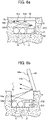
- FIGS. 6a and 6b show an overview of a wireless communication device and a resin container according to the fourth embodiment.
- the first reflectors 54a and 54b are each disposed at a predetermined location inside of the lid 53.
- the second reflectors 54c and 54d are each disposed at predetermined locations inside of the container body 52.
- the first reflectors 54a and 54b, and the second reflector 54c and 54d are, for example, provided in the positions and at the angles as shown in FIG. 6a .
- the first reflectors 54a and 54b, and the second reflector 54c and 54d reflect all the signals transmitted from the second communication unit 212, and those signals are received by the second communication unit 212.
- the one signal transmitted from the second communication unit 212 may be reflected by the first reflector 54a located on the lid 53, then may be reflected by the second reflector 54c located on the container body 52, and may be received by the second communication unit 212.
- the other signal transmitted from the second communication unit 212 may be reflected by the first reflector 54b located on the lid 53, then may be reflected by the second reflector 54d located on the container body 52, and may be received by the second communication unit 212.
- the resin container 5 according to the fourth embodiment is similar to the resin container 5 of the second embodiment, and the first reflector 54a may be located near one end of the lid 53, and the first reflector 54b may be located near the other end of the lid 53.
- the monitoring system 1 can monitor the state of the lid 53 (whether the lid 53 is wide open, the side on which the lid 53 is open, etc.) based on the presence/ absence or the strength of the reflected signals from the respective first reflectors 54a and 54b. This allows the monitoring system 1 to detect an error in the lid 53.
- the monitoring system 1 of the fourth embodiment can monitor the state of the lid 53 with higher precision than the configuration of the resin container 5 according to the first embodiment.
- the monitoring system 1 can also communicate to the monitoring staff information on the location where the wireless communication device 2 is located, as identified by the management device 3. This allows the staff to check the status of the lid 53 in which an error has been detected. Furthermore, the monitoring system 1 can activate an alarm device located near the wireless communication device 2. Therefore, the monitoring system 1 can quickly determine the status of theft, destruction, or other damage to the wireless communication device 2 located in the resin container 5 covered by the lid 53 in which an error has been detected. Furthermore, the monitoring system 1 can also activate an alarm device located near the wireless communication device 2. This can prevent theft or destruction of the wireless communication device 2 located in the resin container 5 covered by the lid 53 in which the error has been detected. [0064].
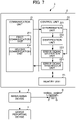
- FIG. 7 shows a block diagram showing functions of the monitoring system 1. As shown in FIG. 7 , the monitoring system 1 includes the wireless communication device 2, the management device 3, and the error reporting device 4.
- the wireless communication device 2 includes the communication unit 21, the control unit 22, and the memory unit 23.
- the communication unit 21 includes a transmitter and a receiver. This transmitter and receiver send and receive signals for wireless communication with external devices.
- the communication unit 21 of the wireless communication device 2 includes a first communication unit 211 and a second communication unit 212.
- the first communication unit 211 communicates with wireless communication apparatuses.
- the second communication unit 212 sends and receives signals to detect an error in the lid 53. It should be noted that, in the present embodiments, components for processing signals transmitted and received by the second communication unit 212 will be explained. In practice, however, the wireless communication device 2 also includes components (not shown) for processing signals transmitted and received by the first communication unit 211.
- the control unit 22 is a CPU (Central Processing Unit).
- the CPU executes programs stored in memory unit 23 so as to function as a determination unit 221, an identification unit 222, an error signal generation unit 223 and an error signal transmission unit 224.
- the determination unit 221 determines whether the state of the lid 53 has changed beyond a certain level based on the signal received by the second communication unit 212. More specifically, the memory unit 23 stores information (waveform, strength, etc.) of signals received when the lid 53 is closing the opening 51. The determination unit 221 analyzes the waveform of the signal received by the second communication unit 212. The determination unit 221 then compares the results of the analysis with the information stored in the memory unit 23. When there is a certain amount of difference between them, the determination unit 221 determines that the state of the lid 53 has changed by a certain amount.
- the wireless communication device 2 determines whether or not the state of the lid 53 has changed beyond a certain level based on the signals received by the second communication unit 212 and the information stored in the memory unit 23.
- the determination unit 221 determines whether the state of the lid 53 has changed beyond a certain level based on the electric field strength of the signal received by the second communication unit 212.
- the determination unit 221 uses Received Signal Strength Indicator (RSSI) for measuring the electric field strength to determine whether the state of the body 53 has changed beyond a certain level.
- RSSI Received Signal Strength Indicator
- a memory unit 23 stores the electric field strength of the signal received when the lid 53 is closing the opening 51.
- the determination unit 221 measures the electric field strength of the signal received by the second communication unit 212.
- the determination unit 221 then compares the measurement results with the electric field strengths stored in the memory unit 23. When there is a difference beyond a certain level between them, the determination unit 221 determines that the state of the lid 53 has changed beyond a certain level.
- the wireless communication device 2 can determine whether the state of the lid 53 has changed beyond a certain level based on the electric field strength of the signal received by the second communication unit 212 and the electric field strength stored in the memory unit 23.
- the determination unit 221 may compare the pattern of the electric field strength of the signal with the pattern stored in the memory unit 23 based on the comparison result, and determine whether the state of the lid 53 has changed beyond a certain level.
- the pattern of the electric field strength of the signal is expressed, for example, as a waveform pattern of the electric field strength of the signal within a fixed period of time.
- a fixed period of time is, for example, a few seconds, tens of seconds, or minutes.
- the determination unit 22 uses pattern matching to determine whether the pattern of the electric field strength of the signal received by the second communication unit 212 within a fixed period of time matches the pattern stored in the memory unit 23.
- the determination unit 221 uses the pattern of the electric field strength of the signal as described above.
- the present invention is not limited thereto.
- the determination unit 221 may determine that the state of the lid 53 has changed by a certain amount. For example, when a signal is received by the second communication unit 212 in a case where the lid 53 is displaced and the distance between the second communication unit 212 and the reflector in the resin container 5 becomes far, the electric field strength of the signal is considered to be equal to or less than a predetermined threshold value.
- the electric field strength of the signal is considered to be greater than the predetermined threshold value.
- the wireless communication device 2 can determine whether the state of the lid 53 has changed beyond a certain level based on the pattern of the field strength of the signal received by the second communication unit 212 and the pattern of the field strength of the signal received by the memory unit 23.
- the identification unit 222 identifies the change in the state of the lid 53. More specifically, the identification unit 222 compares the pattern of the electric field strength of the signal with the pattern stored in the memory unit 23, and then identifies the change in the state of the lid 53 based on the result of said comparison.
- the memory unit 23 has a table T.
- a plurality of patterns of the electric field strength of the signal are associated with a plurality of changes in the state of the lid 53 indicated by the patterns.
- the first pattern indicating the electric field strength of the signal is associated with the change in the state of the lid 53, which is "the side near the one end of the lid is open”
- the second pattern indicating the electric field strength of the signal is associated with the change in the state of the lid 53, which is "the lid is flexing inward”
- third pattern indicating the electric field strength of the signal is associated with the change in the state of the lid 53, which is "the lid is flapping".
- the identification unit 222 measures the pattern of the electric field strength of the signal received by the second communication unit 212. The identification unit 222 then refers to the table T stored in the memory unit 23. Thereafter, the identification unit 222 identifies the change in the state of the lid 53 corresponding to the pattern of the measured electric field strength.
- the wireless communication device 2 can specifically identify the change in the state of the lid 53 based on the pattern of the electric field strength of the signal received by the second communication unit 212 and the table stored in the memory unit 23.
- the signal transmitted from the second communication unit 212 is not reflected by the first reflectors 54a and 54b and not received by the second communication unit 212. Therefore, in this case, the pattern of the electric field strength of the signal is unmeasurable.
- the wireless communication device 2 identifies the change in the state of the lid 53 as the lid 53 being displaced.
- the electric field strength of the signal fluctuates between the lid 53 being open and closed. Therefore, the pattern of the electric field strength of the signal repeatedly becomes stronger and weaker.
- the error signal generation unit 223 When the determination unit 221 determines that the state of the lid 53 has changed beyond a certain level, the error signal generation unit 223 generates an error signal indicating an error in the lid 53. Furthermore, the error signal may include a signal indicating the change in the state of the lid 53 identified by the identification unit 222.
- the error signal transmission unit 224 transmits an error signal generated by the error signal generation unit 223 to the management device 3.
- the error signal is transmitted by wireless communication or by wired communication through the communication line 6 provided in the resin container 5.
- the memory unit 23 is, for example, a storage unit such as ROM (Read Only Memory) storing the Operating System (OS), application programs, etc., RAM (Random Access Memory), hard disk drives and SSD (Solid State Drives) for storing various pieces of information, and other storage devices.
- the memory unit 23 stores, for example, one or more of the patterns indicating the change in the state of the lid 53 described above.
- the management device 3 is connected to the wireless communication device 2 by wireless communication or by wired communication via the communication line 6.
- the management device 3 receives an error signal from the wireless communication device 2, the management device 3 generates a reporting signal to report the error in the lid 53 based on the error signal.
- the management device 3 then transmits the reporting signal to the error reporting device 4.
- the error reporting device 4 receives the reporting signal from the management device 3 and reports the error in the lid 53 based on the reporting signal. There are various possible ways in which the error can be reported by the error reporting device 4. For example, an alarm device, which is the error reporting device 4 installed in the vicinity of the wireless communication device 2, may report by alarm. An alarm system, which is the error reporting device 4 installed around the wireless communication device 2, may also operate.
- the management device 3 may also transmit the reporting signal to an unmanned flying vehicle D, such as a drone.
- the unmanned flying vehicle D is directed by flight to the resin container 5 covered by the lid 53 in which an error has been detected.
- the unmanned flying vehicle D takes pictures of the area around the resin container 5 with its onboard camera.
- the administrator can monitor live images taken by the unmanned flying vehicle D to identify the error in the lid 53.
- the wireless communication device 2 located in the resin container 5 is stolen or destroyed at this time, the police or other authorities can be reported.
- error reporting device 4 may also control monitoring cameras or other devices installed around the wireless communication device 2 to monitor the status of the wireless communication device 2.
- the first communication unit 211 may not only communicate with wireless communication apparatuses, but also have a function of sending and receiving signals to monitor the state of the lid 53. In this configuration, the wireless communication device 2 does not need the second communication unit 212. Therefore, cost reduction can be achieved.
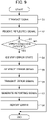
- FIG. 9 is a flowchart showing the process flow of the monitoring system 1.
- the second communication unit 212 transmits the signal. This signal is used to monitor the status of the resin container 5.
- the second communication unit 212 receives the signal reflected by the first reflectors 54a and 54b, and the second reflectors 54c and 54d.
- step S3 the determination unit 221 determines whether the state of the lid 53 has changed beyond a certain level based on the signal received by the second communication unit 212.
- the processing advances to step S4, and when the state of the lid 53 has not changed (NO), the processing ends.
- step S4 the identification unit 222 identifies the change in the state of the lid 53.
- step S5 the error signal generation unit 223 generates an error signal indicating an error in the lid 53.
- step S6 the error signal transmission unit 224 transmits the error signal generated by the error signal generation unit 223 to the management device 3 via wireless communication or wired communication through the communication line 6.
- step S7 when the management device 3 receives the error signal, the management device 3 generates a reporting signal reporting the error in the lid 53 based on the received error signal, and transmits the generated reporting signal to the error reporting device 4.
- step S8 the error reporting device 4 receives the reporting signal from the management device 3. The error reporting device 4 then reports the error of the wireless communication device 2 based on the reporting signal.
- the monitoring system 1 can monitor the status of the lid 53 based on the signal reflected by the reflector provided on the lid 53. This allows the monitoring system 1 to detect whether there is an error in the lid 53 (for example, the lid 53 is open).
- the monitoring system 1 can also communicate, to the monitoring staff, information on the location where the wireless communication device 2 is located, as identified by the management device 3. This allows the staff to check the status of the lid 53 in which an error has been detected. Furthermore, the monitoring system 1 can activate an alarm device located near the wireless communication device 2. Therefore, the monitoring system 1 can quickly determine the status of theft, destruction, or other damage to the wireless communication device 2 located in the resin container 5 covered by the lid 53 in which an error has been detected. Furthermore, the monitoring system 1 can also activate an alarm device located near the wireless communication device 2. This can prevent theft or destruction of the wireless communication device 2 located in the resin container 5 covered by the lid 53 in which the error has been detected.
Landscapes
- Engineering & Computer Science (AREA)
- Radar, Positioning & Navigation (AREA)
- Remote Sensing (AREA)
- Physics & Mathematics (AREA)
- General Physics & Mathematics (AREA)
- Computer Networks & Wireless Communication (AREA)
- Burglar Alarm Systems (AREA)
- Processing And Handling Of Plastics And Other Materials For Molding In General (AREA)
Applications Claiming Priority (2)
| Application Number | Priority Date | Filing Date | Title |
|---|---|---|---|
| JP2019211027 | 2019-11-22 | ||
| PCT/JP2020/043495 WO2021100870A1 (ja) | 2019-11-22 | 2020-11-20 | 樹脂容器および監視装置 |
Publications (2)
| Publication Number | Publication Date |
|---|---|
| EP4064237A1 true EP4064237A1 (de) | 2022-09-28 |
| EP4064237A4 EP4064237A4 (de) | 2023-12-13 |
Family
ID=75981608
Family Applications (1)
| Application Number | Title | Priority Date | Filing Date |
|---|---|---|---|
| EP20888823.0A Withdrawn EP4064237A4 (de) | 2019-11-22 | 2020-11-20 | Harzbehälter und überwachungsvorrichtung |
Country Status (5)
| Country | Link |
|---|---|
| US (1) | US20220283280A1 (de) |
| EP (1) | EP4064237A4 (de) |
| JP (1) | JPWO2021100870A1 (de) |
| AU (1) | AU2020385850A1 (de) |
| WO (1) | WO2021100870A1 (de) |
Families Citing this family (1)
| Publication number | Priority date | Publication date | Assignee | Title |
|---|---|---|---|---|
| JP7898580B1 (ja) * | 2025-07-05 | 2026-07-31 | 株式会社新昭和 | ケーブル盗難防止システム |
Family Cites Families (17)
| Publication number | Priority date | Publication date | Assignee | Title |
|---|---|---|---|---|
| US4017863A (en) * | 1976-03-10 | 1977-04-12 | The United States Of America As Represented By The Secretary Of The Navy | Hardened electromagnetic wave energy sensor |
| US4314243A (en) * | 1980-03-04 | 1982-02-02 | Phelps Clifford R | Well pump theft alarm |
| JPH0643049U (ja) * | 1992-11-17 | 1994-06-07 | 二宮産業株式会社 | 地上孔蓋落下防止構造 |
| JP2591471B2 (ja) * | 1994-05-11 | 1997-03-19 | 日本電気株式会社 | 画像処理装置 |
| US20080210852A1 (en) * | 2003-03-21 | 2008-09-04 | Browning Thomas E | Fiber optic security system for sensing the intrusion of secured locations |
| US7402790B2 (en) * | 2003-05-03 | 2008-07-22 | Woven Electronics, Llc | Fiber optic security system for sensing the intrusion of secured locations |
| US7323986B2 (en) * | 2004-09-03 | 2008-01-29 | Gore Enterprise Holdings, Inc. | Reusable tamper respondent enclosure |
| US20060071770A1 (en) * | 2004-10-04 | 2006-04-06 | Frank Giotto | Fiber optic cable sensor for movable objects |
| US7456738B2 (en) * | 2005-06-01 | 2008-11-25 | Thermo King Corporation | Transport refrigeration door status sensing device |
| WO2007058302A1 (ja) * | 2005-11-21 | 2007-05-24 | Nec Corporation | 位置推定システム、位置推定方法および位置推定用プログラム |
| JP2007320655A (ja) * | 2006-05-30 | 2007-12-13 | Thermo King Corp | 輸送冷凍ドア状態検知装置 |
| US8368552B2 (en) * | 2009-12-22 | 2013-02-05 | At&T Intellectual Property I, L.P. | Manhole security device and methods thereof |
| US9001002B2 (en) * | 2011-09-30 | 2015-04-07 | Apple Inc. | Portable electronic device housing having insert molding around antenna |
| ITGE20120014U1 (it) * | 2012-02-23 | 2013-08-24 | Def Di R Doni S P A | Dispositivo antifurto per cavi, in particolare cavi elettrici e nei cavidotti o simili |
| FR3011396B1 (fr) * | 2013-09-30 | 2016-01-15 | Nexans | Dispositif d'alerte pour enceinte de cheminement de cables |
| WO2015156096A1 (ja) | 2014-04-10 | 2015-10-15 | 日本電気株式会社 | 無線通信構造及び無線通信方法 |
| EP3660978B1 (de) | 2017-08-24 | 2022-09-28 | Ntt Docomo, Inc. | Antennenvorrichtung, drahtlose basisstation und antennenvorrichtungsbehälter |
-
2020
- 2020-11-20 JP JP2021558480A patent/JPWO2021100870A1/ja not_active Withdrawn
- 2020-11-20 WO PCT/JP2020/043495 patent/WO2021100870A1/ja not_active Ceased
- 2020-11-20 AU AU2020385850A patent/AU2020385850A1/en not_active Abandoned
- 2020-11-20 EP EP20888823.0A patent/EP4064237A4/de not_active Withdrawn
-
2022
- 2022-05-23 US US17/664,450 patent/US20220283280A1/en not_active Abandoned
Also Published As
| Publication number | Publication date |
|---|---|
| WO2021100870A1 (ja) | 2021-05-27 |
| EP4064237A4 (de) | 2023-12-13 |
| AU2020385850A1 (en) | 2022-07-07 |
| JPWO2021100870A1 (de) | 2021-05-27 |
| US20220283280A1 (en) | 2022-09-08 |
Similar Documents
| Publication | Publication Date | Title |
|---|---|---|
| US8294568B2 (en) | Wireless mine tracking, monitoring, and rescue communications system | |
| US8395513B2 (en) | Technique for detecting tracking device tampering using an auxiliary device | |
| US8354925B1 (en) | Monitoring using RF communication technology | |
| US9405948B2 (en) | Method for monitoring the functioning of an RFID-based radio communication network in a spatially extensive area | |
| EP2224407A1 (de) | Behälternachverfolgung | |
| US10534404B2 (en) | Wireless network systems and related methods for marine applications | |
| US20150145684A1 (en) | Auxiliary device for a hazard alarm constructed as a point type detector for function monitoring of the hazard alarm, and an arrangement and method of monitoring using a device of this kind | |
| US20080164984A1 (en) | Security System for Vehicles, Trucks and Shipping Containers | |
| CN103282591A (zh) | 用于远程跟踪挂锁的状态检测器和通信单元以及系统 | |
| US10068462B2 (en) | Systems and methods for manual tamper reset in a monitoring system | |
| CN109410537A (zh) | 一种可监测偷拍设备的装置及其控制方法 | |
| JP2018513447A (ja) | センサ装置の動作方法及びセンサ装置 | |
| US10097952B2 (en) | Systems and methods for monitoring altitude sensing beacons | |
| US20220283280A1 (en) | Resin container and monitoring device | |
| KR20200034892A (ko) | 무선 통신 시스템에서 기지국의 방위각 결정 방법 및 장치 | |
| JP3674161B2 (ja) | テレメータ・テレコントロール装置 | |
| CN111406258B (zh) | 对资产进行安全本地访问并利用移动设备进行验证的装置、包括该装置的系统和方法 | |
| EP3571521B1 (de) | System und verfahren zum erfassen der bewegung eines mobilen vermögenswertes und steuerungsoperationen des vermögenswertes auf basis seiner bewegung | |
| KR20180047038A (ko) | 드론의 GPS 수신 신호 이상시 LoRa를 이용한 드론 위치정보 획득 시스템 및 그 방법 | |
| US9148796B2 (en) | Resilient antenna disturbance detector | |
| US20070149139A1 (en) | Wireless Network System with Energy Management | |
| KR100862186B1 (ko) | 이동 감지 센서를 구비한 이동 노드 및 동체 감지 센서를구비한 고정 노드간 저전력 구현 및 이동 노드의 식별자의중복 전송을 방지하기 위한 방법 및 이동 노드 | |
| KR102347461B1 (ko) | 원격 조종이나 자율 이동 가능한 이동체를 위한 해킹 방지 장치 및 방법 | |
| US10113900B2 (en) | Field device with multiple protocol support | |
| KR102534328B1 (ko) | 통신과 감지 겸용의 현장 단말기 |
Legal Events
| Date | Code | Title | Description |
|---|---|---|---|
| STAA | Information on the status of an ep patent application or granted ep patent |
Free format text: STATUS: THE INTERNATIONAL PUBLICATION HAS BEEN MADE |
|
| PUAI | Public reference made under article 153(3) epc to a published international application that has entered the european phase |
Free format text: ORIGINAL CODE: 0009012 |
|
| STAA | Information on the status of an ep patent application or granted ep patent |
Free format text: STATUS: REQUEST FOR EXAMINATION WAS MADE |
|
| 17P | Request for examination filed |
Effective date: 20220614 |
|
| AK | Designated contracting states |
Kind code of ref document: A1 Designated state(s): AL AT BE BG CH CY CZ DE DK EE ES FI FR GB GR HR HU IE IS IT LI LT LU LV MC MK MT NL NO PL PT RO RS SE SI SK SM TR |
|
| DAV | Request for validation of the european patent (deleted) | ||
| DAX | Request for extension of the european patent (deleted) | ||
| REG | Reference to a national code |
Ref country code: DE Ref legal event code: R079 Free format text: PREVIOUS MAIN CLASS: G08B0013184000 Ipc: G08B0013080000 |
|
| A4 | Supplementary search report drawn up and despatched |
Effective date: 20231110 |
|
| RIC1 | Information provided on ipc code assigned before grant |
Ipc: G08B 25/10 20060101ALN20231106BHEP Ipc: G08B 25/08 20060101ALN20231106BHEP Ipc: G01S 13/88 20060101ALN20231106BHEP Ipc: G01S 13/00 20060101ALN20231106BHEP Ipc: G01S 7/00 20060101ALN20231106BHEP Ipc: H01Q 1/04 20060101ALI20231106BHEP Ipc: H01Q 19/10 20060101ALI20231106BHEP Ipc: G08B 13/08 20060101AFI20231106BHEP |
|
| STAA | Information on the status of an ep patent application or granted ep patent |
Free format text: STATUS: THE APPLICATION IS DEEMED TO BE WITHDRAWN |
|
| 18D | Application deemed to be withdrawn |
Effective date: 20240529 |