EP4064188B1 - Verarbeitung von multimodalen netzhautbildern - Google Patents
Verarbeitung von multimodalen netzhautbildern Download PDFInfo
- Publication number
- EP4064188B1 EP4064188B1 EP22164127.7A EP22164127A EP4064188B1 EP 4064188 B1 EP4064188 B1 EP 4064188B1 EP 22164127 A EP22164127 A EP 22164127A EP 4064188 B1 EP4064188 B1 EP 4064188B1
- Authority
- EP
- European Patent Office
- Prior art keywords
- oct
- data
- image
- feature
- retina
- Prior art date
- Legal status (The legal status is an assumption and is not a legal conclusion. Google has not performed a legal analysis and makes no representation as to the accuracy of the status listed.)
- Active
Links
Images


Classifications
-
- A—HUMAN NECESSITIES
- A61—MEDICAL OR VETERINARY SCIENCE; HYGIENE
- A61B—DIAGNOSIS; SURGERY; IDENTIFICATION
- A61B3/00—Apparatus for testing the eyes; Instruments for examining the eyes
- A61B3/0016—Operational features thereof
- A61B3/0025—Operational features thereof characterised by electronic signal processing, e.g. eye models
-
- A—HUMAN NECESSITIES
- A61—MEDICAL OR VETERINARY SCIENCE; HYGIENE
- A61B—DIAGNOSIS; SURGERY; IDENTIFICATION
- A61B3/00—Apparatus for testing the eyes; Instruments for examining the eyes
- A61B3/0016—Operational features thereof
- A61B3/0041—Operational features thereof characterised by display arrangements
- A61B3/0058—Operational features thereof characterised by display arrangements for multiple images
-
- A—HUMAN NECESSITIES
- A61—MEDICAL OR VETERINARY SCIENCE; HYGIENE
- A61B—DIAGNOSIS; SURGERY; IDENTIFICATION
- A61B3/00—Apparatus for testing the eyes; Instruments for examining the eyes
- A61B3/10—Objective types, i.e. instruments for examining the eyes independent of the patients' perceptions or reactions
- A61B3/102—Objective types, i.e. instruments for examining the eyes independent of the patients' perceptions or reactions for optical coherence tomography [OCT]
-
- A—HUMAN NECESSITIES
- A61—MEDICAL OR VETERINARY SCIENCE; HYGIENE
- A61B—DIAGNOSIS; SURGERY; IDENTIFICATION
- A61B3/00—Apparatus for testing the eyes; Instruments for examining the eyes
- A61B3/10—Objective types, i.e. instruments for examining the eyes independent of the patients' perceptions or reactions
- A61B3/12—Objective types, i.e. instruments for examining the eyes independent of the patients' perceptions or reactions for looking at the eye fundus, e.g. ophthalmoscopes
- A61B3/1225—Objective types, i.e. instruments for examining the eyes independent of the patients' perceptions or reactions for looking at the eye fundus, e.g. ophthalmoscopes using coherent radiation
-
- A—HUMAN NECESSITIES
- A61—MEDICAL OR VETERINARY SCIENCE; HYGIENE
- A61B—DIAGNOSIS; SURGERY; IDENTIFICATION
- A61B3/00—Apparatus for testing the eyes; Instruments for examining the eyes
- A61B3/10—Objective types, i.e. instruments for examining the eyes independent of the patients' perceptions or reactions
- A61B3/14—Arrangements specially adapted for eye photography
-
- G—PHYSICS
- G06—COMPUTING OR CALCULATING; COUNTING
- G06T—IMAGE DATA PROCESSING OR GENERATION, IN GENERAL
- G06T11/00—2D [Two Dimensional] image generation
- G06T11/001—Texturing; Colouring; Generation of texture or colour
-
- G—PHYSICS
- G06—COMPUTING OR CALCULATING; COUNTING
- G06T—IMAGE DATA PROCESSING OR GENERATION, IN GENERAL
- G06T5/00—Image enhancement or restoration
- G06T5/50—Image enhancement or restoration using two or more images, e.g. averaging or subtraction
-
- G—PHYSICS
- G06—COMPUTING OR CALCULATING; COUNTING
- G06T—IMAGE DATA PROCESSING OR GENERATION, IN GENERAL
- G06T7/00—Image analysis
- G06T7/0002—Inspection of images, e.g. flaw detection
- G06T7/0012—Biomedical image inspection
-
- G—PHYSICS
- G06—COMPUTING OR CALCULATING; COUNTING
- G06T—IMAGE DATA PROCESSING OR GENERATION, IN GENERAL
- G06T7/00—Image analysis
- G06T7/30—Determination of transform parameters for the alignment of images, i.e. image registration
- G06T7/33—Determination of transform parameters for the alignment of images, i.e. image registration using feature-based methods
-
- G—PHYSICS
- G06—COMPUTING OR CALCULATING; COUNTING
- G06T—IMAGE DATA PROCESSING OR GENERATION, IN GENERAL
- G06T7/00—Image analysis
- G06T7/50—Depth or shape recovery
-
- G—PHYSICS
- G06—COMPUTING OR CALCULATING; COUNTING
- G06V—IMAGE OR VIDEO RECOGNITION OR UNDERSTANDING
- G06V30/00—Character recognition; Recognising digital ink; Document-oriented image-based pattern recognition
- G06V30/10—Character recognition
- G06V30/19—Recognition using electronic means
- G06V30/191—Design or setup of recognition systems or techniques; Extraction of features in feature space; Clustering techniques; Blind source separation
- G06V30/19107—Clustering techniques
-
- G—PHYSICS
- G06—COMPUTING OR CALCULATING; COUNTING
- G06T—IMAGE DATA PROCESSING OR GENERATION, IN GENERAL
- G06T11/00—2D [Two Dimensional] image generation
- G06T11/60—Editing figures and text; Combining figures or text
-
- G—PHYSICS
- G06—COMPUTING OR CALCULATING; COUNTING
- G06T—IMAGE DATA PROCESSING OR GENERATION, IN GENERAL
- G06T2200/00—Indexing scheme for image data processing or generation, in general
- G06T2200/24—Indexing scheme for image data processing or generation, in general involving graphical user interfaces [GUIs]
-
- G—PHYSICS
- G06—COMPUTING OR CALCULATING; COUNTING
- G06T—IMAGE DATA PROCESSING OR GENERATION, IN GENERAL
- G06T2207/00—Indexing scheme for image analysis or image enhancement
- G06T2207/10—Image acquisition modality
- G06T2207/10024—Color image
-
- G—PHYSICS
- G06—COMPUTING OR CALCULATING; COUNTING
- G06T—IMAGE DATA PROCESSING OR GENERATION, IN GENERAL
- G06T2207/00—Indexing scheme for image analysis or image enhancement
- G06T2207/10—Image acquisition modality
- G06T2207/10072—Tomographic images
- G06T2207/10101—Optical tomography; Optical coherence tomography [OCT]
-
- G—PHYSICS
- G06—COMPUTING OR CALCULATING; COUNTING
- G06T—IMAGE DATA PROCESSING OR GENERATION, IN GENERAL
- G06T2207/00—Indexing scheme for image analysis or image enhancement
- G06T2207/20—Special algorithmic details
- G06T2207/20081—Training; Learning
-
- G—PHYSICS
- G06—COMPUTING OR CALCULATING; COUNTING
- G06T—IMAGE DATA PROCESSING OR GENERATION, IN GENERAL
- G06T2207/00—Indexing scheme for image analysis or image enhancement
- G06T2207/20—Special algorithmic details
- G06T2207/20092—Interactive image processing based on input by user
- G06T2207/20101—Interactive definition of point of interest, landmark or seed
-
- G—PHYSICS
- G06—COMPUTING OR CALCULATING; COUNTING
- G06T—IMAGE DATA PROCESSING OR GENERATION, IN GENERAL
- G06T2207/00—Indexing scheme for image analysis or image enhancement
- G06T2207/20—Special algorithmic details
- G06T2207/20092—Interactive image processing based on input by user
- G06T2207/20104—Interactive definition of region of interest [ROI]
-
- G—PHYSICS
- G06—COMPUTING OR CALCULATING; COUNTING
- G06T—IMAGE DATA PROCESSING OR GENERATION, IN GENERAL
- G06T2207/00—Indexing scheme for image analysis or image enhancement
- G06T2207/20—Special algorithmic details
- G06T2207/20212—Image combination
-
- G—PHYSICS
- G06—COMPUTING OR CALCULATING; COUNTING
- G06T—IMAGE DATA PROCESSING OR GENERATION, IN GENERAL
- G06T2207/00—Indexing scheme for image analysis or image enhancement
- G06T2207/20—Special algorithmic details
- G06T2207/20212—Image combination
- G06T2207/20221—Image fusion; Image merging
-
- G—PHYSICS
- G06—COMPUTING OR CALCULATING; COUNTING
- G06T—IMAGE DATA PROCESSING OR GENERATION, IN GENERAL
- G06T2207/00—Indexing scheme for image analysis or image enhancement
- G06T2207/30—Subject of image; Context of image processing
- G06T2207/30004—Biomedical image processing
- G06T2207/30041—Eye; Retina; Ophthalmic
Definitions
- Example aspects herein generally relate to the field of retinal image processing and, more particularly, to the processing of a reflectance image of a retina to include supplementary information derived from optical coherence tomography (OCT) data acquired from the retina.
- OCT optical coherence tomography
- Two-dimensional images of the ocular fundus acquired by a fundus camera or a scanning laser ophthalmoscope (SLO), for example, are widely used to detect various eye diseases, as well as systemic diseases in a subject.
- these imaging methods tend to have a varying sensitivity with depth in the retina, their depth specificity tends to be low, so that the depth of an observed feature in a retinal fundus image is usually uncertain.
- some common eye diseases such as age-related macular degeneration, diabetic retinopathy and retinal vein occlusion, are associated with features such as hyper-reflective dots which furthermore have a similar appearance in retinal fundus image, it is often difficult for a clinician to distinguish between these diseases from an inspection of a retinal fundus image alone.
- Artefacts in retinal fundus images such as those resulting from a highly reflective inner limiting membrane (ILM), and atrophy of the retinal pigment epithelium (RPE) may also confuse the identification of disease-related features, such as exudative, RPE-related and drusenoid hyper-reflective dots. Further information on a feature of interest that has been identified on a retinal fundus image may be obtained by examining an OCT thickness map which covers the feature of interest.
- ILM inner limiting membrane
- RPE retinal pigment epithelium
- US 2012/0075584 A1 discloses various methods for mapping OCT data to facilitate review and diagnosis.
- high resolution 2D line scans are obtained along with lower density 3D cube scans and displayed in a manner to provide context to the clinician.
- OCT data is analysed to provide information about non-uniformities of the tissue.
- Binary image maps of maps useful for determining tautness of membranes are also disclosed.
- multi-directional OCT a technique for investigation of the scattering properties of directionally reflective tissue samples.
- This approach enables simultaneous acquisition of multiple reflectivity depth-scans probing a mutual sample location from differing angular orientations.
- the application of multi-directional OCT in retinal imaging allows for in-depth investigations on the directional reflectivity of the retinal nerve fiber layer, Henle's fiber layer and the photoreceptor layer.
- Major ophthalmic diseases (such as glaucoma or age-related macular degeneration) have been reported to alter the directional reflectivity properties of these retinal layers.
- the concept of multidirectional OCT might help to gain improved understanding of pathology development and progression.
- US 2016/0284103 A1 discloses technology relating to analysis of images and particularly, but not exclusively, to methods and systems for determining the area and/or volume of a region of interest using optical coherence tomography data. Some examples provide for determining the area and/or volume of a lesion in retinal tissue using three-dimensional optical coherence tomography data and a two-dimensional optical coherence tomography fundus image.
- the present invention provides a computer-implemented method according to Claim 1, a computer program according to Claim 13, a non-transitory computer-readable storage medium according to Claim 14, and an apparatus according to Claim 15.
- Optional features are set out in the dependent claims.
- a computer-implemented method of processing image data defining a fundus image of a portion of a retina of an eye to include supplementary information on a designated feature in the fundus image comprises designating a feature in the fundus image, receiving optical coherence tomography (OCT) data of a C-scan of the portion of the retina, and selecting a subset of the OCT data which represents a volumetric image of a part of the retina at a location on the retina corresponding to a location of the designated feature in the fundus image.
- OCT optical coherence tomography
- the method further comprises processing the selected subset of the OCT data to generate, as the supplementary information, supplementary image data indicative of a variation, along a depth direction of the retina, of a measured reflectance of the eye in the selected subset of the OCT data.
- the method further comprises generating combined image data by combining the image data with the supplementary image data, such that a combined image defined by the combined image data provides an indication of the variation of the measured reflectance of the eye in the selected subset of the OCT data at the designated feature.
- the combined image data is generated by replacing pixel values of a subset of pixels of the fundus image data with pixel values of the supplementary image data, such that a combined image defined by the combined image data provides an indication of the variation of the measured reflectance of the eye in the selected subset of the OCT data at the designated feature.
- the combined image data may be generated by replacing pixel values of a subset of pixels of the fundus image data, which subset of pixels defines a subregion of the fundus image which is at the location of the designated feature in the fundus image, with pixel values of the supplementary image data, such that a combined image defined by the combined image data provides an indication of the variation of the measured reflectance of the eye in the selected subset of the OCT data at the designated feature.
- the supplementary image data may define a graphic which is indicative of the variation, along the depth direction of the retina, of the measured reflectance of the eye in the selected subset of the OCT data or, more specifically, how the measured reflectance of the eye, as indicated in the selected subset of the OCT data varies along a depth direction of the retina.
- the combined image data may be generated by replacing pixel values of a subset of pixels of the fundus image data with pixel values of the supplementary image data such that a combined image defined by the combined image data comprises the graphic, which is overlaid on the fundus image so as to provide an indication of the variation of the measured reflectance of the eye in the selected subset of the OCT data at the designated feature.
- the computer-implemented method set out above may, in accordance with an example embodiment, further comprise causing the fundus image and a cursor to be displayed on a display, such that the cursor can be controlled to move over the displayed fundus image by a signal from a user input device, wherein the feature in the fundus image is designated by recording, in response to a feature designation command, a value of a first location indicator that is indicative of a display location of the cursor on the displayed fundus image.
- the method of the example embodiment may further comprise: processing the OCT data to generate an OCT en-face image of the portion of the retina; and causing the OCT en-face image to be displayed on the display together with the fundus image, such that the cursor can be controlled to move over the displayed OCT en-face image by the signal from the user input device, wherein the subset of the OCT data is selected based on a value of a second location indicator, which is indicative of a display location of the cursor when the cursor has been guided by the signal from the user input device to overlay a part of the displayed OCT en-face image which corresponds to the designated feature in the displayed fundus image.
- the feature in the fundus image may alternatively be designated automatically by a feature extraction algorithm.
- the computer-implemented method may further comprise: causing the fundus image and a feature location indicator, which indicates a location of the designated feature in the fundus image, to be displayed on a display; processing the OCT data to generate an OCT en-face image of the portion of the retina; and causing the OCT en-face image and a cursor to be displayed on the display together with the fundus image, such that the cursor can be controlled to move over the displayed OCT en-face image by a signal from a user input device, wherein the subset of the OCT data is selected based on a value of a second location indicator, which is indicative of a display location of the cursor when the cursor has been guided by the signal from the user input device to overlay a part of the displayed OCT en-face image whose location corresponds to the location of the designated feature in the fundus image that is indicated by the feature location indicator.
- the subset of the OCT data may be selected by applying a geometric transformation, which maps locations in the fundus image to corresponding A-scan locations in the OCT data, to the location of the feature in the fundus image which has been designated by the feature extraction algorithm.
- the feature may be one of a dot and a hyper-reflective dot in the fundus image, the feature having a pathological cause or being caused by a reflection from an inner limiting membrane of the retina.
- the feature may have a pathological cause comprising one of blood leakage, exudation, drusen, atrophy and/or naevi in the retina, and atrophy of a retinal pigment epithelium in the retina.
- the selected subset of the OCT data may be processed to generate the supplementary image data by the following scheme 1, scheme 2 or scheme 3.
- the selected subset of the OCT data is processed to generate the supplementary image data by: detecting a plurality of anatomical layers of the eye in the selected subset of the OCT data, the anatomical layers comprising one or more retinal layers of the retina; calculating, for each of at least two of the detected anatomical layers, a respective sum value by summing values of data elements of the subset of the OCT data in the anatomical layer; calculating, for each of the at least two of the detected anatomical layers, a respective ratio between the sum value calculated for the anatomical layer and a sum of all the data elements that are in the at least two of the detected anatomical layers and in the subset of the OCT data; and generating, as the supplementary image data, and based on an ordered sequence of the calculated ratios, wherein the calculated ratios are arranged in order of the corresponding anatomical layers in the eye, colour information defining a colour which is to be displayed in the combined image and identifies the ordered sequence of the calculated ratios, such that the
- the colour information may be generated by assigning, to each of a red colour component, a green colour component and a blue colour component of the colour to be displayed in the combined image, a respective weighting for the colour component in accordance with a respective one of the calculated ratios in the ordered sequence of the calculated ratios.
- the selected subset of the OCT data is processed to generate the supplementary image data by: detecting a plurality of anatomical layers of the eye in the selected subset of the OCT data, the anatomical layers comprising one or more retinal layers of the retina; calculating, for each anatomical layer of the detected anatomical layers, a respective sum value by summing values of data elements of the subset of the OCT data in the anatomical layer; selecting, based on the calculated sum values, an anatomical layer of the detected anatomical layers which provides a dominant contribution to the measured reflectance of the eye; and generating, as the supplementary image data, graphic image data defining a graphic which identifies the selected anatomical layer.
- the selected subset of the OCT data represents a volumetric image of a part of the retina having a feature of a predetermined type and is processed to generate the supplementary image data by: training a model for determining a depth of the feature of the predetermined type in the depth direction of the retina, by supervised learning of examples of OCT data of pathological regions of at least one other retina, each of the examples of OCT data comprising a single OCT A-scan or two or more adjacent OCT A-scans, and each of the pathological regions having a respective feature of the predetermined type, wherein an indication of a respective depth of the respective feature in the depth direction of the retina in each of the examples of OCT data is specified by a user during the training; processing the selected subset of the OCT data using the trained model to determine the depth of the feature in the depth direction of the retina; and generating, as the supplementary image data, one of (i) graphic image data defining a graphic which indicates the determined depth of the feature and is to be overlaid on the fundus image (
- a computer program comprising computer program instructions which, when executed by a computer, cause the computer to perform the method set out above.
- the computer program may be stored on a non-transitory computer-readable storage medium, or it may be carried by a signal.
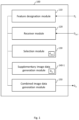
- an apparatus for processing image data defining a fundus image of a portion of a retina of an eye to include supplementary information on a designated feature in the fundus image comprises a feature designation module arranged to designate a feature in the fundus image, and a receiver module arranged to receive OCT data of a C-scan of the portion of the retina.
- the apparatus further comprises a selection module arranged to select a subset of the OCT data which represents a volumetric image of a part of the retina at a location on the retina corresponding to a location of the designated feature in the fundus image, and a supplementary image data generation module arranged to process the selected subset of the OCT data to generate, as the supplementary information, supplementary image data indicative of a variation, along a depth direction of the retina, of a measured reflectance of the eye in the selected subset of the OCT data.
- the apparatus further comprises a combined image data generation module arranged to generate combined image data by combining the image data with the supplementary image data, such that a combined image defined by the combined image data provides an indication of the variation at the designated feature.
- the combined image data generation module is arranged to generate the combined image data by replacing pixel values of a subset of pixels of the fundus image data with pixel values of the supplementary image data, such that a combined image defined by the combined image data provides an indication of the variation of the measured reflectance of the eye in the selected subset of the OCT data at the designated feature.
- the combined image data generation module may be arranged to generate the combined image data by replacing pixel values of a subset of pixels of the fundus image data, which subset of pixels defines a subregion of the fundus image which is at the location of the designated feature in the fundus image, with pixel values of the supplementary image data, such that a combined image defined by the combined image data provides an indication of the variation of the measured reflectance of the eye in the selected subset of the OCT data at the designated feature.
- the supplementary image data generation module may be arranged to generate supplementary image data which defines a graphic indicative of the variation, along the depth direction of the retina, of the measured reflectance of the eye in the selected subset of the OCT data or, more specifically, how the measured reflectance of the eye, as indicated in the selected subset of the OCT data varies along a depth direction of the retina.
- the combined image data generation module may be arranged to generate the combined image data by replacing pixel values of a subset of pixels of the fundus image data with pixel values of the supplementary image data such that a combined image defined by the combined image data comprises the graphic, which is overlaid on the fundus image so as to provide an indication of the variation of the measured reflectance of the eye in the selected subset of the OCT data at the designated feature.
- retinal fundus image data may assist a clinician to assess a distribution of, and distinguish between, features of some common eye diseases which have similar appearance in retinal fundus images, such as diabetic retinopathy, age-related macular degeneration and retinal vein occlusion, and that may help avoid misreading of retinal fundus images caused by specular imaging artefacts.
- the techniques described herein may allow additional information in OCT data to be leveraged for a clearer rendering of features (e.g. bright spots) in the retinal fundus images.
- the information can be assimilated by the user without reviewing OCT data.
- the user may be notified of whether a feature in a retinal fundus image is coincident with a feature in OCT, thereby helping to avoid misinterpretation of artefactual spots and the like in the retinal fundus image.
- FIG 1 is a schematic illustration of an apparatus 100 for processing image data according to a first example embodiment.
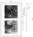
- the apparatus 100 is arranged to process received image data D F , which defines a fundus image 10 of a portion of a retina of an eye, to include supplementary information on a designated feature 12 in the fundus image 10, as illustrated in Fig. 2 , where the fundus image 10 and the designated feature 12 are shown to be displayed on a display 14 (e.g. a visual display unit, such as a computer monitor), together with a user-controlled cursor 16.
- a display 14 e.g. a visual display unit, such as a computer monitor
- the fundus image of the retina (also referred to herein as a retinal fundus image) 10 may be acquired by any fundus imaging process by which a two-dimensional representation of the three-dimensional (semi-transparent) retinal tissues projected onto an imaging plane of a fundus imaging apparatus (not shown) is obtained using light collected from the retina.
- the fundus image may be acquired by illumination of the retina by global illumination or by a scanned light beam provided by the fundus imaging apparatus.
- the light reflected from the retina is collected by a receiver of the fundus imaging apparatus, and its position-dependent intensity is detected, and then converted into the image data D F representing the two-dimensional fundus image 10.
- the term 'fundus imaging' used herein refers to any process which results in a two-dimensional image of a portion of the retina, wherein image pixel values represent respective intensities of light collected from the retina, and is to be contrasted with OCT imaging (discussed below).
- the fundus image 10 may be acquired by one of many types of fundus imaging apparatus known to those versed in the art, including but not limited to fundus cameras and scanning laser ophthalmoscopes (SLOs). In combination with light filters, these types of fundus imaging apparatus may be used to acquire monochromatic or autofluorescence images of the fundus and, with the injection of intravenous contrast material, may also be used to acquire fundus fluorescein angiograms, indocyanine green angiograms and the like. Fundus imaging thus covers various modalities/techniques, including monochromatic fundus photography, colour fundus photography, scanning laser ophthalmoscopy (SLO), adaptive optics SLO, fluorescein angiography and indocyanine angiography.
- SLO scanning laser ophthalmoscopy
- the fundus imaging apparatus may have a relatively narrow field of view or 30°-55° or so that is typical in conventional fundus imaging, or it may be a widefield fundus imaging apparatus having a field of view of about 100°.
- the fundus imaging apparatus may be an ultra-widefield (UWF TM ) fundus imaging apparatus having a field of view of about 200°, such as the Optos California TM system made by Optos plc.
- UWF TM ultra-widefield
- the apparatus 100 comprises a feature designation module 110, which is arranged to designate a feature 12 in the fundus image 10 received from the fundus imaging apparatus.
- the feature 12 may be an image of a structure having a relatively high reflectivity (whether inside the retina or in another part of the eye being imaged), and may therefore be a part of the fundus image 10 representing higher reflectance than a region of the fundus image 10 surrounding that part.
- the feature 12 may alternatively be an image of a structure having a relatively low reflectivity (whether inside the retina or in another part of the eye being imaged), and may therefore be a part of the fundus image 10 representing lower reflectance than a region of the fundus image 10 surrounding that part.
- the feature 12 may, for example, be a dot feature, whose extent in the fundus image is small compared to the size of the fundus image.
- Dot features of this kind can have a pathological cause, such as blood leakage, exudation, drusen, atrophy and/or naevi in the retina.
- Dot features related to these pathologies have a very similar, characteristic appearance (in terms of their sizes and the brightness difference between dot features and their surroundings in the fundus image 10), and are difficult for a clinician to disambiguate by inspection of the fundus image 10 alone.
- the dot feature may be a hyper-reflective dot/focus, for example, which is often observed in retinal fundus images.
- Hyper-reflective foci may have a pathological cause such as blood leakage, exudation, drusen, atrophy and/or naevi in the retina or atrophy of a retinal pigment epithelium in the retina, or a non-pathological cause such as a reflection from an inner limiting membrane of the retina.
- Hyper-reflective dots in all these cases have a very similar, characteristic appearance, and are difficult to distinguish by inspection of the fundus image 10 alone.
- the feature designation module 110 may designate the feature 12 in the fundus image 10 in one of a number of different ways.
- the feature designation module 110 causes the fundus image 10 and the cursor 16 to be displayed on the display 14.
- the display location of the cursor 16 on the displayed fundus image 10 is controllable by a signal from a user input device 18, such as a computer mouse, a trackpad or the like.
- the feature 12 in the fundus image 10 is designated by recording, in response to a feature designation command, a value of a first location indicator that is indicative of a display location of the cursor 16 when the cursor has been guided by the signal to overlay the displayed fundus image 10.
- the feature designation module 110 may cause a graphic 19 to be overlaid on the reluctance image 10 at the location in the fundus image 10 indicated by the first location indicator.
- the feature designation command may, as in the present example embodiment, be provided by the user, for example by the user operating the user input device 18 (e.g. providing a mouse click in case the user input device is provided in the form of a computer mouse, or a finger tap in case the user input device is provided in the form of a trackpad).
- the feature designation command may alternatively be provided by the user operating another user input device, for example pressing a key on a computer keyboard.
- the feature designation command may be generated by the feature designation module 110 in response to a prescribed condition being met, for example the expiry of a predetermined time period which is started by a display on the display 14 of an instruction to the user to designate a feature of interest in the displayed fundus image 10.
- the feature designation module 110 need not rely on such a human interaction to designate the feature 12, and may, in an alternative example embodiment, perform the designation automatically, using one of a number of feature extraction algorithms known to those versed in the art, for example as described in " Automated detection of age-related macular degeneration in color fundus photography: a systematic review" by Pead, E., Megaw, R., Cameron, J., Fleming, A., Dhillon, B., Trucco, E. and MacGillivray, T., 2019, published in Survey of Ophthalmology, 64(4), 2019 at pages 498-511 , or " A review on exudates detection methods for diabetic retinopathy" by Joshi, S. and Karule, P.
- the apparatus 100 also has a receiver module 120, which is arranged to receive optical OCT data D OCT of a C-scan (shown at 20 in Fig. 3 ) of the portion of the retina acquire by an OCT imaging system (not shown).
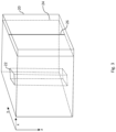
- the apparatus 100 also has a selection module 130, which is arranged to select a subset d OCT of the OCT data D OCT , which represents a volumetric image (defined by voxels of a set 22 of A-scans in Fig. 3 ) of a part of the retina at a location on the retina corresponding to a location of the designated feature 12 in the fundus image 10. As illustrated schematically in Fig.
- the C-scan 20 is composed of a series of B-scans 24, wherein each B-scan 24 is composed of a series of A-scans 26.
- the value of each data element in an A-scan 26 provides an indication of a measured reflectance of the eye at a respective location in the depth direction of the retina that corresponds to the location of the data element along the A-scan 26 (i.e. along the z-axis direction in Fig. 3 ).
- the location of the A-scan 26 along the y-axis and x-axis directions of data element array forming the C-scan 20 corresponds to a location on the retina of a measurement taken by the OCT imaging system to acquire the A-scan 26.
- the OCT imaging system used to acquire the OCT data D OCT may be of any type known to those versed in the art, for example a point-scan OCT imaging system, which can acquire an OCT image by scanning a laser beam laterally across a region of the eye.
- the OCT imaging system may alternatively be a parallel acquisition OCT imaging system, such as Full-Field OCT (FF-OCT) or Line-Field OCT (LF-OCT), which may offer superior A-scan acquisition rates (up to tens of MHz) by illuminating an area or a line on the sample, rather than scanning a single spot across the eye.
- FF-OCT Full-Field OCT
- LF-OCT Line-Field OCT
- FF-OCT a two-dimensional region of the eye is illuminated at the same time and the lateral positions across the region are concurrently captured using a photodetector array such as a high-speed charge-coupled device (CCD) camera.
- CCD charge-coupled device
- the OCT imaging system is a Full-field OCT, it may take the form of a full-field time-domain OCT (FF-TD-OCT) or full-field swept-source OCT (FF-SS-OCT), for example.
- FF-TD-OCT the optical length of the reference arm can be varied during a scan in order to image regions at different depths in the eye.
- Each frame captured by the high-speed camera in FF-TD-OCT therefore corresponds to a slice of the eye at a respective depth within the eye.
- the sample region is full-field illuminated using a swept light source that emits light whose wavelength varies over time.
- a spectrogram correlating reflectivity information against optical wavelength can be generated by the high-speed camera for each camera pixel.
- Each frame captured by the camera therefore corresponds to reflectivity information for a single wavelength of the swept light source.
- a C-scan of the region can be obtained by performing a Fourier transform on the samples of spectrograms generated by the camera.
- LF-OCT line-field OCT
- a line of illumination may be provided to the sample and a B-scan may be acquired in the imaging process.
- Line-field OCT may be classified as line-field time-domain OCT (LF-TD-OCT), line-field swept-source OCT (LF-SS-OCT), or line-field spectral-domain OCT (LF-SD-OCT), for example.
- the OCT imaging system used to acquire the OCT data and the fundus imaging apparatus used to acquire the fundus image may be separate devices. It should be noted, however, that the fundus image and the OCT data may be acquired by a single, multimodal retinal imaging system, such as the Silverstone combined UWF retinal imaging device and UWF-guided swept source OCT scanner made by Optos plc.
- the subset d OCT of the received OCT data D OCT may, as in the present example embodiment, be selected by the selection module 130 based on an input from a user who has inspected a two-dimensional representation of the OCT data D OCT shown on the display 14, determined a location in the representation of the OCT data D OCT which corresponds to the location of the designated feature 12 in the reference image 10 also shown on the display 14, and guided the cursor 16 to overlay the determined location in the representation of the OCT data D OCT .
- the selection module 130 processes the received OCT data D OCT to generate an OCT en-face image of the portion of the retina.
- the OCT en-face image 30 is a projection of the (three-dimensional) C-scan 20 image to the same two-dimensional plane that would be viewed in the fundus image 10 of the same portion of the retina.
- the generation of the OCT en-face image 30 may involve a summation, a weighted summation or a maximisation of the data elements (voxels) of the C-scan along the depth axis (z) of the OCT C-scan 20.
- the selection module 130 causes the OCT en-face image 30 to be displayed on the display 14 together with the fundus image 10, for example alongside the fundus image 10 as illustrated in Fig. 2 , with the cursor 16 being controllable by the signal from the user input device 18 to move over the displayed OCT en-face image 30.
- the display 14 is provided in the form of a single visual display unit in the present example embodiment, the display 14 may alternatively be provided in the form of a first monitor (or other visual display unit) and a second monitor (or other visual display unit, not necessarily of the same kind as the first visual display unit), which are arranged to respectively display the fundus image 10 and the OCT en-face image 30 simultaneously to the user.
- the subset d OCT of the OCT data D OCT is selected by the selection module 130 based on a value of a second location indicator that is indicative of a display location of the cursor 16 when the cursor 16 has been guided by the signal from the user input device 18 to overlay a part 32 of the displayed OCT en-face image 30 which is judged by the user (based on a comparison of retinal features in the displayed images 10 and 30) to correspond to the designated feature 12 in the displayed fundus image 10, and in response to a feature designation commend of the kind described above.
- the subset d OCT of the OCT data D OCT may be selected based on the value of a second location indicator by mapping the value of the second location indicator to an A-scan of the OCT C-scan 20 having a corresponding (x, y) coordinate, and selecting the A-scan, or the A-scan together with a predefined arrangement of neighbouring (adjacent) A-scans (e.g. m adjacent A-scans that are nearest to the mapped to- and selected A-scan in the x-y plane of the C-scan 20, where m is an integer, preferably greater than 4 and more preferably greater than 8), as the subset d OCT of the OCT data D OCT .
- a predefined arrangement of neighbouring (adjacent) A-scans e.g. m adjacent A-scans that are nearest to the mapped to- and selected A-scan in the x-y plane of the C-scan 20, where m is an integer, preferably greater
- the subset d OCT of the OCT data D OCT need not be defined by the mapped to- and selected A-scan together with a predefined arrangement of neighbouring A-scans but may alternatively be defined by a set of A-scans that are enclosed by a contour in the x-y plane of the C-scan 20 defied by straight-line segments linking A-scans of the C-scan 20 that have been selected based on respective values of the second location indicator, in response to the user issuing multiple feature designation commands as he/she moves the cursor 16 around the boundary of a feature of interest in the fundus image 10.
- the subset d OCT of the OCT data D OCT may therefore correspond to a region of the OCT en-face image 30 having a predefined shape (as in the present example embodiment) or a shaped defined by the user.
- the selection module 130 may cause a graphic 34 to be overlaid on the OCT en-face image 30 at the location in the en-face image 30 indicated by the second location indicator.
- the graphic 34 may the same as the graphic 19, or different from graphic 19 in case a different colour and/or shape for the graphic 34 provides better visibility on the OCT en-face image 30, for example.
- the appearance of the cursor 16 whilst overlaying the displayed fundus image 10 may be different (in terms of shape and/or colour) from its appearance whilst overlaying the displayed OCT en-face image 30.
- the selection module 130 may cause a feature location indicator (e.g. in the form of graphic 19) to be overlaid on the displayed fundus image 10, so as to indicate the location of the designated feature 12 in the fundus image 10.
- a feature location indicator e.g. in the form of graphic 19
- the subset d OCT of the OCT data D OCT may be selected based on a value of the second location indicator as described above, which is indicative of a display location of the cursor 16 when the cursor 16 has been guided by the signal from the user input device 18 to overlay a part of the displayed OCT en-face image 30 whose location is judged by the user (based on a comparison of retinal features in the displayed images 10 and 30) to correspond to the location in the fundus image 10 indicated by the feature location indicator.
- the correspondence between the location of the designated feature 12 in the fundus image 10 and the location of the subset d OCT within OCT data D OCT need not be determined by a user from an inspection of a displayed fundus image 10 and a displayed OCT en-face image of a common portion of the retina.
- the location of the subset d OCT within OCT data D OCT may be determined automatically, on the basis of the location of the designated feature 12 in the fundus image 10, by use of a predetermined geometric transformation.
- the predetermined geometric transformation maps locations in the fundus image 10 to corresponding A-scan locations in the OCT data, and may be applied by the selection module 130 to the location of the feature 12 in the fundus image 10 that has been designated by the feature extraction algorithm, in order to identify a corresponding A-scan location in the C-scan 20 of an A-scan 26 which is to be included in the subset d OCT of the OCT data (optionally, together with one or more adjacent A-scans in the C-scan 20).
- the geometric transformation may be determined in one of a number of different ways.
- the geometric transformation may be determined by registering image data D F defining the fundus image 10 with image data defining an OCT en-face image 30 that has been generated as described above, without the OCT en-face image 30 being displayed to the user.
- Any intensity- and/or feature-based registration algorithm know to those versed in the art may be used to determine the geometric transformation and thus establish a point-to-point correspondence between locations in the fundus image 10 and lateral positions (defined by coordinates along the x- and y-axes in Fig. 3 ) in the OCT C-scan 20.
- registration algorithms may operate directly on the two-dimensional dataset defining the fundus image 10 and the three-dimensional dataset defining the OCT C-scan 20, rather than on the two-dimensional dataset defining the fundus image 10 and the two-dimensional dataset of the OCT en-face image 30 that is derived from the three-dimensional dataset of the OCT C-scan 20.
- both the designation of a feature in the fundus image 10 by the feature designation module 110, and the selection of the subset d OCT of the OCT data D OCT by the selection module 130 may be performed automatically (i.e. without any user input).
- the feature designation module 110 may designate a part of the image data D F defining a feature 12 in the fundus image 10 using a feature extraction algorithm, and the selection module 130 may select the subset d OCT of the OCT data D OCT by applying the geometric transformation described above to the location of the designated part in the image data D F of the fundus image 10.
- the designation of the feature 12 and the selection of the subset d OCT of the OCT data is performed without displaying any representation of the image data D F of the fundus image 10 or of the OCT data D OCT to the user, and without requiring any user input.
- the apparatus 100 also has a supplementary image data generation module 140-1, which is arranged to process the selected subset d OCT of the OCT data D OCT to generate, as the supplementary information, supplementary image data D SI indicative of a variation, along the depth direction of the retina (i.e. the direction in which light rays enter the retina), of a measured reflectance of the eye in the selected subset d OCT of the OCT data.
- a supplementary image data generation module 140-1 is arranged to process the selected subset d OCT of the OCT data D OCT to generate, as the supplementary information, supplementary image data D SI indicative of a variation, along the depth direction of the retina (i.e. the direction in which light rays enter the retina), of a measured reflectance of the eye in the selected subset d OCT of the OCT data.
- the apparatus 100 also has a combined image data generation module 150-1, which is arranged to generate combined image data D CI by combining the image data D F with the supplementary image data D SI , such that a combined image defined by the combined image data D CI provides an indication of the variation of the measured reflectance of the eye in the selected subset d OCT of the OCT data D OCT at the designated feature.
- a combined image data generation module 150-1 which is arranged to generate combined image data D CI by combining the image data D F with the supplementary image data D SI , such that a combined image defined by the combined image data D CI provides an indication of the variation of the measured reflectance of the eye in the selected subset d OCT of the OCT data D OCT at the designated feature.
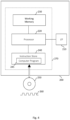
- Figure 4 is a schematic illustration of a programmable signal processing hardware 200, which may be configured to perform the operations of the apparatus 100 of the first example embodiment.
- the programmable signal processing apparatus 200 includes a communication interface (I/F) 210, for communicating with the fundus imaging apparatus and the OCT imaging system (or with the combined imaging system mentioned above, which is capable of generating both the image data D F defining the fundus image 10 and the OCT data D OCT of a subject retina) to receive the image data D F of the fundus image 10 and the OCT data D OCT therefrom.
- the signal processing apparatus 200 further includes a processor (e.g. a Central Processing Unit, CPU) 220, a working memory 230 (e.g. a random access memory) and an instruction store 240 storing a computer program 245 comprising computer-readable instructions which, when executed by the processor 220, cause the processor 220 to perform various functions of the apparatus 100 described herein.
- a processor e.g. a Central Processing Unit, CPU
- working memory 230 e.g. a random access memory
- an instruction store 240 storing a computer program 245 comprising computer-readable instructions which, when executed by the
- the working memory 230 stores information used by the processor 220 during execution of the computer program 245.
- the instruction store 240 may include a ROM (e.g. in the form of an electrically-erasable programmable read-only memory (EEPROM) or flash memory) which is pre-loaded with the computer-readable instructions.
- the instruction store 240 may include a RAM or similar type of memory, and the computer-readable instructions of the computer program 245 can be input thereto from a computer program product, such as a non-transitory, computer-readable storage medium 250 in the form of a CD-ROM, DVD-ROM, etc. or a computer-readable signal 260 carrying the computer-readable instructions.
- the computer program 24 when executed by the processor 220, causes the processor 220 to execute a method of processing the image data to include the supplementary information described herein.
- the apparatus 100 may alternatively be implemented in non-programmable hardware, such as an application-specific integrated circuit (ASIC).
- ASIC application-specific integrated circuit
- Figure 5 is a flow diagram illustrating a method by which the apparatus 100 of Fig. 1 processes the image data D F defining the fundus image 10 to include supplementary information on a designated feature 12 in the fundus image 10.
- the feature designation module 110 designates a feature 12 in the reflectance image 10 of a portion of a retina that is defined by image data D F received from a fundus imaging apparatus, as described above.
- process S20 of Fig. 5 the receiver module 120 receives OCT data D OCT of an OCT C-scan of the portion of the retina, as described above.
- process S20 is illustrated to occur following process S10 in Fig. 5 , it will be appreciated that the order in which these processes are performed may be reversed, and that at least parts of these processes may be performed concurrently.
- the section module 130 selects a subset d OCT of the received OCT data D OCT which represents a volumetric image of a part of the retina at a location on the retina corresponding to a location of the designated feature 12 in the fundus image 10, as described above.
- the supplementary image data generation module 140-1 processes the selected subset d OCT of the OCT data D OCT to generate, as the supplementary information, supplementary image data D SI that is indicative of a variation, along a depth direction of the retina, of a measured reflectance of the eye in the selected subset d OCT of the OCT data D OCT .
- the supplementary image data D SI indicates how the measured reflectance of the eye, as indicated by the voxels in the selected subset d OCT of the OCT data D OCT , varies along the depth direction of the retina.
- the supplementary image data D SI may chart the variation of the measured reflectance of the eye, as indicated by the voxels in the selected subset d OCT of the OCT data D OCT , with position along the depth direction of the retina.
- the supplementary image data D SI may thus provide a profile of the measured reflectance along the depth direction of the retina.
- the supplementary image data generation module 140-1 processes the selected subset d OCT of the OCT data D OCT to generate the supplementary image data D SI by a method which will now be described with reference to Fig. 6 .
- the supplementary image data generation module 140-1 detects a plurality of anatomical layers in the selected subset d OCT of the OCT data D OCT .
- the anatomical layers are anatomically distinct structures of the eye that overlie each other and may be distinguished in the depth axis of an OCT image because of differences in their light diffusive characteristics.
- the anatomical layers include anatomical layers that are present in the posterior segment of the eye, including one or more layers of the retina of the eye. Each layer has an inner surface and an outer surface (relative to the vitreous of the eye).
- the retina can be divided into 10 layers, namely: (1) the inner limiting membrane (ILM); (2) the nerve fiber layer (NFL); (3) the ganglion cell layer (GCL); (4) the inner plexiform layer (IPL); (5) the inner nuclear layer (INL); (6) the outer plexiform layer (OPL); (7) the outer nuclear layer (ONL); (8) the outer limiting membrane (OLM); (9) the photoreceptor layer (PL); and (10) the retinal pigmented epithelium (RPE) monolayer.
- ILM inner limiting membrane
- NNL nerve fiber layer
- GCL ganglion cell layer
- IPL inner plexiform layer
- IPL inner nuclear layer
- OPL outer plexiform layer
- OLM outer nuclear layer
- PL photoreceptor layer
- RPE retinal pigmented epithelium
- the supplementary image data generation module 140-1 may detect the anatomical layers in the selected subset d OCT of the OCT data D OCT using one of a number of types of algorithm for ocular layer segmentation known to those skilled in the art, a review of which is provided in " A Review of Algorithms for Segmentation of Optical Coherence Tomography from Retina” by R. Kafieh et al, J Med Signals Sens. 2013 Jan-Mar; 3(1): 45-60 .
- An anatomical layer segmentation algorithm is thus used in process S42 to generate layer identification information identifying the boundaries (i.e.
- the detected anatomical layers in the selected subset d OCT of the OCT data D OCT which can be used to identify a respective set of data elements (voxels) in the selected subset d OCT of the OCT data D OCT belonging to each of the detected anatomical layers.
- the supplementary image data generation module 140-1 calculates, for each of the detected anatomical layers, a respective sum value by summing values of data elements (voxels) in the subset d OCT of the OCT data in the respective anatomical layer. In other words, the supplementary image data generation module 140-1 generates a sum value S i for each anatomical layer L i of the n detected anatomical layers, L 1 ,...
- n is an integer greater than or equal to 2, which have been identified using the anatomical layer identification information, by summing values of voxels that are located along the A-scans in the subset d OCT of the OCT data D OCT so as to be between the inner surface and the outer surface of the anatomical layer L i .
- the supplementary image data generation module 140-1 generates colour information (as the supplementary image data D SI ) based on an ordered sequence of the calculated ratios r 1 to r n , wherein the calculated ratios r 1 to r n are arranged in the same order as the order in which the corresponding anatomical layers are arranged in the posterior segment of the eye.
- the colour information is generated so as to define a colour to be displayed in the combined image that uniquely identifies the ordered sequence of the calculated ratios r 1 to r n .
- the colour displayed in the combined image, at the location of the designated feature 12, is therefore indicative of the variation of the measured reflectance of the eye in the selected subset d OCT of the OCT data D OCT along the depth direction of the retina.
- processes S44 to S48 in Fig. 6 need not operate on all of the anatomical layers in the selected subset d OCT of the OCT data D OCT that have been detected in process S42 of Fig. 6 , and may instead operate on at least two of these anatomical layers.
- Processes S44 to S48 in Fig. 6 operate on one or more detected anatomical layers forming part of the retina, and may additionally operate on one or more anatomical layers that do not form part of the retina, such as a sub-retinal layer which includes the choroid and pathological sub-retinal fluid, for example.
- a first anatomical layer L 1 , a second anatomical layer L 2 , and a third anatomical layer L 3 are detected by the supplementary image data generation module 140-1 in process S42 of Fig. 6 .
- the supplementary image data generation module 140-1 generates respective sum values S 1 , S 2 and S 3 for the anatomical layers L 1 , L 2 and L 3 , and calculates (in process S46 of Fig. 6 ) respective ratios r 1 , r 2 and r 3 for the anatomical layers L 1 , L 2 and L 3 .
- r 1 is calculated as S 1 /(S 1 +S 2 +S 3 ).
- the supplementary image data generation module 140-1 generates the colour information by assigning, to each of a red colour component R, a green colour component G and a blue colour component B of the colour to be displayed in the combined image, a respective weighting, w R , w G or w B , for the colour component in accordance with a respective one of the calculated ratios r 1 , r 2 or r 3 in the ordered sequence r 1 ; r 2 ; r 3 of the calculated ratios. For instance, in an example where the ratios calculated in process S46 of Fig.
- the display of a yellow colour in the combined image would indicate that anatomical layers L 1 and L 2 provide the main contribution to the measured reflectance.
- the display of a cyan colour in the combined image would indicate that layers L 2 and L 3 provide the main contribution to the measured reflectance.
- the combined image data generation module 150-1 generates the combined image data D CI by combining the image data D F with the supplementary image data D SI , such that a combined image defined by the combined image data D CI provides an indication of the variation at the designated feature 12.
- the combined image data generation module 150-1 may be arranged to generate the combined image data D CI by replacing pixel values of a subset of pixels of the fundus image data D F with pixel values of the supplementary image data D SI , such that a combined image defined by the combined image data D CI provides an indication of the variation of the measured reflectance of the eye in the selected subset d OCT of the OCT data D OCT at the designated feature 12.
- the combined image data generation module 150-1 may be arranged to generate the combined image data D CI by replacing pixel values of a subset of pixels of the fundus image data D F , which subset of pixels defines a subregion of the fundus image which is at the location of the designated feature 12 in the fundus image 10, with pixel values of the supplementary image data D SI , such that a combined image defined by the combined image data D CI provides an indication of the variation of the measured reflectance of the eye in the selected subset d OCT of the OCT data D OCT at the designated feature 12.
- the combined image data generation module 150-1 may, as in the present example embodiment, generate the combined image data D CI by modifying the image data D F such that pixel values in the fundus image 10, which are at pixel locations corresponding to pixel locations in the OCT en-face image 30 showing data from the selected subset d OCT of the OCT data D OCT , are replaced by pixel values representing the colour determined by the supplementary image data generation module 140-1 for that subset d OCT of the OCT data D OCT .
- the aforementioned correspondence between pixel locations in the fundus image 10 and the OCT en-face image 30 may be determined by the geometric transformation discussed above.
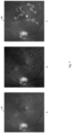
- Image A in Fig. 7 is an example of a fundus image 10, which shows several features of interest that are highlighted in image B of Fig. 7 .
- the curves bounding the features of interest that are shown in image B are based on an output from a feature extraction algorithm.
- Image C of Fig. 7 is an example of a combined image 40, wherein the regions of the fundus image 10 highlighted in image B are coloured in accordance with the colour information generated by the supplementary image data generation module 140-1.
- regions 41, 42 and 43 are predominantly blue
- regions 44 and 45 are predominantly red
- region 46 is predominantly white
- the remaining regions are predominantly green.
- Regions 41-43 relate to features of the retina that are nearest the (inner) retinal surface, specifically within the inner and outer neurological retina, which is a first anatomical layer detected in this example.
- Figure 8 shows an image of a B-scan taken along the horizontal line in image C of Fig. 7 . Regions of the retina in Fig 8 , which correspond to those in Fig. 7 where the horizontal line crosses regions 41 and 42, have a higher reflectance near the inner surface of the retina (towards the top of Fig. 8 ) than the surrounding regions of the retina in Fig. 8 .
- the predominantly green regions relate to features of a deeper retinal layer that is detected in this example, which is the retinal pigment epithelium (RPE) in this example.
- Regions 44 and 45 relate to yet deeper features that are farthest the retinal surface, and lie within the choroid or pathological subretinal fluid, which are in the third anatomical layer that is detected in this example.
- Figure 9 is a schematic illustration of an apparatus 300 for processing image data according to a second example embodiment.
- the apparatus 300 of the second example embodiment differs from the apparatus 100 of the first example embodiment by the arrangement of the supplementary image data generation module 140-2, which is arranged to generate a different kind of supplementary image data, D' SI .
- the apparatus 300 of the second example embodiment is the same as apparatus 100 of the first example embodiment, as described above.
- the supplementary image data generation module 140-2 processes the selected subset d OCT of the OCT data D OCT to generate the supplementary image data D SI by a method which is a variant of the method described above with reference to Fig. 6 , and which will now be described with reference to Fig. 10 .
- Processes S42 and S44 in Fig. 10 are the same as processes S42 and S44 in Fig. 6 , and will therefore not be described again here.
- the supplementary image data generation module 140-2 selects, based on the sum values calculated in process S44, an anatomical (e.g. retinal) layer of the detected layers L 1 to L n which provides a dominant contribution to the measured reflectance of the among the detected layers for which the sum values have been calculated.
- the supplementary image data generation module 140-2 may, as in the present example embodiment, select the anatomical layer that provides a dominant contribution by selecting the layer for which the calculated sum value is largest among the detected layers for which the sum values have been calculated.
- the supplementary image data generation module 140-2 generates, as the supplementary image data D' SI , graphic image data defining a graphic which identifies the selected anatomical layer, for example by a text label naming the layer (in full or in an abbreviated form, for example).
- the graphic need not such a self-contained identification of the selected anatomical layer, however, and may comprise a pattern, for example, which the viewer can use to identify the selected anatomical layer by reference to a legend (showing an association between different forms (e.g. patterns) of the graphic and corresponding named anatomical layers) that is also displayed on the screen.
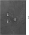
- the combined image data generation module 150 is arranged to generate the combined image data D' CI by combining the image data D F with the graphic image data such that the combined image is an annotated version of the fundus image 10, wherein the graphic is overlaid on the fundus image 10 (and preferably shaped, for example to have a pointed feature such as an arrow or the like) so as to indicate the location of designated feature 12. Examples of such an annotated version of the fundus image 10 are shown in Figs. 11 and 12 .
- the combined image data generation module 150 is arranged to generate the combined image data D' CI by replacing pixel values of a subset of pixels of the fundus image data with pixel values of the supplementary image data D' SI , such that a combined image defined by the combined image data D' CI provides an indication of the variation of the measured reflectance of the eye in the selected subset of the OCT data at the designated feature 12.
- the supplementary image data generation module 140-2 may be arranged to generate supplementary image data which defines a graphic that is indicative of the variation, along the depth direction of the retina, of the measured reflectance of the eye in the selected subset of the OCT data or, more particularly, how the measured reflectance of the eye, as indicated in the selected subset of the OCT data varies along a depth direction of the retina.
- the combined image data generation module 150 may be arranged to generate the combined image data D' CI by replacing pixel values of a subset of pixels of the fundus image data with pixel values of the supplementary image data D' SI such that a combined image defined by the combined image data D' CI comprises the graphic, which is overlaid on the fundus image 10 so as to provide an indication of the variation of the measured reflectance of the eye in the selected subset of the OCT data at the designated feature 12.
- the label “INL” is overlaid on the fundus image so as to indicate the location in the fundus image of a feature that is located in the inner nuclear layer (INL) of the retina
- the label “GCL” is overlaid on the fundus image so as to indicate the location in the fundus image of a feature that is located in the ganglion cell layer (GCL) of the retina.
- the label “None” is overlaid on the fundus image indicates that the associated feature in the fundus image is not located within any layer of the retina.
- the label "RPE” is overlaid on the fundus image so as to indicate the location in the fundus image of a feature that is located in the retinal pigment epithelium (RPE) of the retina
- the label "ILM” is overlaid on the fundus image so as to indicate the location in the fundus image of a feature that is located in the inner limiting membrane (ILM) that lies between the retina and the vitreous body.
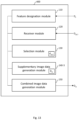
- Figure 13 is a schematic illustration of an apparatus 400 for processing image data according to a third example embodiment.
- the apparatus 400 of the third example embodiment differs from the apparatus of the first and second example embodiments by the arrangement of the supplementary image data generation module 140-3, which is arranged to generate the supplementary information described in these example embodiments in a different way.
- the apparatus 300 of the second example embodiment is the same as apparatus 100 of the first example embodiment, as described above.
- the selected subset d OCT of the OCT data D OCT represents a volumetric image of a part of the retina (possibly in addition to another part of the for example beneath the outer surface of the retina) having a feature of a predetermined type and is processed by the supplementary image data generation module 140-3 to generate the supplementary image data D SI by a method which will now be described with reference to Fig. 14 .
- a model for determining a depth of the feature of the predetermined type in the depth direction of the retina is trained by supervised learning of examples of OCT data of pathological regions of at least one other retina.
- Each of these examples of OCT data comprises a single OCT A-scan or two or more adjacent OCT A-scans, and each of the pathological regions has a respective feature of the predetermined type.
- an indication of a respective depth of the respective feature in the depth direction of the retina in each of the examples of OCT data is specified by a user.
- the model may also be provided with the locations of retinal layers in the A-scan(s) and, in the training process, the model may learn to output the depth of the feature when given the A-scan (or a group of adjacent A-scans) and the layers as input.
- the depth of the feature may be specified in several ways.
- the depth is usually defined relative to one or more retinal layers.
- the depth may be defined in terms of a number of pixels or as a linear measurement (assuming pixel dimensions have been previously estimated) relative to one of the retinal layers.
- the innermost or outermost retinal surfaces may provide suitable reference points for this measurement.
- the depth may be defined relative to multiple retinal layers which have been identified by automated means. In this case, the depth may be indicated by the name of the layer that the feature is in and, optionally, the displacement of the feature relative to the inner or outer surface of the layer.
- the depth may be indicated by the name of the layer that the feature is in and a unitless normalised displacement of the feature relative to both inner and outer surfaces of the layer, e.g. such that 0 indicates being at the inner surface of the layer and 1 indicates being at the outer surface of the layer.
- the supplementary image data generation module 140-3 processes the selected subset d OCT of the OCT data D OCT by using the model that has been trained in process S41 to determine the depth of the feature in the depth direction of the retina.
- the supplementary image data generation module 140-3 generates, as the supplementary image data, either (i) graphic image data defining a graphic which indicates the determined depth of the feature and is to be overlaid on the fundus image 10 so as to indicate a location of the feature in the combined image 40, or (ii) colour information defining a colour which is to be displayed at a location of the feature in the combined image and indicates the determined depth of the feature.
- the graphic image data and the colour information may be generated as described above.
- the example aspects described here avoid limitations, specifically rooted in computer technology, relating to the processing of retinal fundus images.
- features of some common eye diseases have similar appearance in fundus images, which may be difficult to disambiguate from specular imaging artefacts and the like.
- additional information in OCT data may be leveraged for a clearer rendering of features in fundus images, which can be assimilated by a user without needing to review OCT data, and which can help the user to avoid misinterpretation of artefactual spots and the like in fundus images.
- the example aspects described herein improve computers and computer processing/functionality, and also improve the field(s) of at least retinal image analysis.
- Software embodiments of the examples presented herein are provided as a computer program, or software, such as one or more programs having instructions or sequences of instructions, included or stored in an article of manufacture such as a machine-accessible or machine-readable medium, an instruction store, or computer-readable storage device, each of which can be non-transitory, in one example embodiment.
- the program or instructions on the non-transitory machine-accessible medium, machine-readable medium, instruction store, or computer-readable storage device may be used to program a computer system or other electronic device.
- the machine- or computer-readable medium, instruction store, and storage device may include, but are not limited to, floppy diskettes, optical disks, and magneto-optical disks or other types of media/machine-readable medium/instruction store/storage device suitable for storing or transmitting electronic instructions.
- the techniques described herein are not limited to any particular software configuration. They may find applicability in any computing or processing environment.
- computer-readable shall include any medium that is capable of storing, encoding, or transmitting instructions or a sequence of instructions for execution by the machine, computer, or computer processor and that causes the machine/computer/computer processor to perform any one of the methods described herein.
- Some embodiments may also be implemented by the preparation of application-specific integrated circuits, field-programmable gate arrays, or by interconnecting an appropriate network of conventional component circuits.
- Some embodiments include a computer program product.
- the computer program product may be a storage medium or media, instruction store(s), or storage device(s), having instructions stored thereon or therein which can be used to control, or cause, a computer or computer processor to perform any of the procedures of the example embodiments described herein.
- the storage medium/instruction store/storage device may include, by example and without limitation, an optical disc, a ROM, a RAM, an EPROM, an EEPROM, a DRAM, a VRAM, a flash memory, a flash card, a magnetic card, an optical card, nanosystems, a molecular memory integrated circuit, a RAID, remote data storage/archive/warehousing, and/or any other type of device suitable for storing instructions and/or data.
- some implementations include software for controlling both the hardware of the system and for enabling the system or microprocessor to interact with a human user or other mechanism utilizing the results of the example embodiments described herein.
- Such software may include without limitation device drivers, operating systems, and user applications.
- Such computer-readable media or storage device(s) further include software for performing example aspects herein, as described above.
- a module includes software, although in other example embodiments herein, a module includes hardware, or a combination of hardware and software.
Landscapes
- Engineering & Computer Science (AREA)
- Health & Medical Sciences (AREA)
- Life Sciences & Earth Sciences (AREA)
- Physics & Mathematics (AREA)
- General Health & Medical Sciences (AREA)
- Medical Informatics (AREA)
- Biomedical Technology (AREA)
- Heart & Thoracic Surgery (AREA)
- Ophthalmology & Optometry (AREA)
- Molecular Biology (AREA)
- Surgery (AREA)
- Animal Behavior & Ethology (AREA)
- Biophysics (AREA)
- Public Health (AREA)
- Veterinary Medicine (AREA)
- Theoretical Computer Science (AREA)
- General Physics & Mathematics (AREA)
- Computer Vision & Pattern Recognition (AREA)
- Radiology & Medical Imaging (AREA)
- Nuclear Medicine, Radiotherapy & Molecular Imaging (AREA)
- Quality & Reliability (AREA)
- Signal Processing (AREA)
- Multimedia (AREA)
- Eye Examination Apparatus (AREA)
Claims (15)
- Computerimplementiertes Verfahren zur Verarbeitung von Bilddaten (DF), die ein Fundusbild (10) eines Teils der Netzhaut eines Auges definieren, umfassend zusätzliche Informationen über ein bestimmtes Merkmal (12) in dem Fundusbild (10), wobei das Verfahren umfasst:Bestimmung (S10) eines Merkmals (12) an einer Stelle im Fundusbild (10);Empfangen (S20) von optischen Kohärenztomographie-, OCT, -daten (DOCT) eines C-Scans (20) des Teils der Netzhaut;Auswählen (S30) einer Teilmenge (dOCT) der OCT-Daten (DOCT), wobei die Teilmenge (dOCT) ein volumetrisches Bild eines Teils der Netzhaut an einer Stelle auf der Netzhaut repräsentiert, die der Stelle des bezeichneten Merkmals (12) im Fundusbild (10) entspricht;Verarbeiten (S40) der ausgewählten Teilmenge (dOCT) der OCT-Daten (DOCT), um als zusätzliche Information zusätzliche Bilddaten (DSI) zu erzeugen, die angeben, wie eine gemessene Reflektanz des Auges, wie in der ausgewählten Teilmenge (dOCT) der OCT-Daten (DOCT) angegeben, entlang einer Tiefenrichtung der Netzhaut variiert; undErzeugen (S50) kombinierter Bilddaten (DCI) durch Kombinieren der Bilddaten (DF) mit den zusätzlichen Bilddaten (DSI), durch Ersetzen von Pixelwerten einer Teilmenge von Pixeln der Bilddaten (DF) durch Pixelwerte der zusätzlichen Bilddaten (DSI), so dass ein kombiniertes Bild (40), das durch die kombinierten Bilddaten (DCI) definiert ist, eine Angabe der Variation der gemessenen Reflektanz des Auges in der ausgewählten Teilmenge (dOCT) der OCT-Daten (DOCT) an dem bezeichneten Merkmal (12) bereitstellt.
- Computerimplementiertes Verfahren nach Anspruch 1, ferner umfassend:Veranlassen, dass das Fundusbild (10) und ein Cursor (16) auf einer Anzeige (14) angezeigt werden, so dass der Cursor (16) durch ein Signal von einer Benutzereingabevorrichtung (18) über das angezeigte Fundusbild (10) bewegt werden kann,wobei das Merkmal (12) in dem Fundusbild (10) durch Aufzeichnung eines Wertes eines ersten Positionsanzeigers, der eine Position der Anzeige des Cursors (16) auf dem angezeigten Fundusbild (10) anzeigt, als Reaktion auf eine Merkmalsbestimmungsanweisung bestimmt wird.
- Computerimplementiertes Verfahren nach Anspruch 2, ferner umfassend:Verarbeiten der OCT-Daten (DOCT), um ein OCT-En-face-Bild (30) des Teils der Netzhaut zu erzeugen; undVeranlassen, dass das OCT-En-Face-Bild (30) zusammen mit dem Fundusbild (10) auf der Anzeige (14) angezeigt wird, so dass der Cursor (16) durch das Signal von der Benutzereingabevorrichtung (18) über das angezeigte OCT-En-Face-Bild (30) bewegt werden kann,wobei die Teilmenge (dOCT) der OCT-Daten (DOCT) basierend auf einem Wert eines zweiten Positionsanzeigers ausgewählt wird, der eine Anzeigeposition des Cursors (16) anzeigt, wenn der Cursor (16) durch das Signal von der Benutzereingabevorrichtung (18) so geleitet wurde, dass er einen Teil des angezeigten OCT-En-Face-Bildes (30) überlagert, der dem bezeichneten Merkmal (12) in dem angezeigten Fundusbild (10) entspricht.
- Computerimplementiertes Verfahren nach Anspruch 1, wobei das Merkmal (12) in dem Fundusbild (10) automatisch durch einen Merkmalsentnahmealgorithmus bestimmt wird.
- Computerimplementiertes Verfahren nach Anspruch 4, ferner umfassend:Veranlassen, dass das Fundusbild (10) und ein Merkmalslokalisierungsindikator (19), der die Position des bezeichneten Merkmals (12) in dem Fundusbild (10) angibt, auf einer Anzeige (14) angezeigt werden;Verarbeiten der OCT-Daten (DOCT), um ein OCT-En-face-Bild (30) des Teils der Netzhaut zu erzeugen; undVeranlassen, dass das OCT-En-Face-Bild (30) und ein Cursor (16) auf der Anzeige (14) zusammen mit dem Fundusbild (10) angezeigt werden, so dass der Cursor (16) durch ein Signal von einer Benutzereingabevorrichtung (18) über das angezeigte OCT-En-Face-Bild (30) bewegt werden kann,wobei die Teilmenge (dOCT) der OCT-Daten (DOCT) basierend auf einem Wert eines zweiten Positionsanzeigers ausgewählt wird, der eine Anzeigeposition des Cursors (16) anzeigt, wenn der Cursor (16) durch das Signal von der Benutzereingabevorrichtung (18) so geleitet wurde, dass er einen Teil des angezeigten OCT-En-Face-Bildes (30) überlagert, dessen Position der Position des bezeichneten Merkmals (12) in dem Fundusbild (10) entspricht, das durch den Merkmalspositionsanzeiger (19) angezeigt wird.
- Computerimplementiertes Verfahren nach Anspruch 4, wobei die Teilmenge (dOCT) der OCT-Daten (DOCT) durch Anwenden einer geometrischen Transformation ausgewählt wird, die eine Zuordnung von Positionen im Fundusbild (10) zu entsprechenden A-Scan-Positionen in den OCT-Daten (DOCT) zu der Position des Merkmals (12) im Fundusbild (10) vornimmt, das durch den Merkmalsentnahmealgorithmus bestimmt wurde.
- Computerimplementiertes Verfahren nach einem der vorstehenden Ansprüche, wobei das Merkmal (12) eines von einem Punkt und einem hyperreflektiven Punkt in dem Fundusbild (10) ist, wobei das Merkmal (12) eine pathologische Ursache aufweist oder durch eine Reflexion von einer inneren Grenzmembran der Netzhaut bewirkt wird.
- Computerimplementiertes Verfahren nach Anspruch 7, wobei das Merkmal (12) eine pathologische Ursache aufweist, umfassend Blutleckage, Exsudation, Drusen, Atrophie und/oder Naevi in der Retina und Atrophie eines retinalen Pigmentepithels in der Netzhaut.
- Computerimplementiertes Verfahren nach einem der vorstehenden Ansprüche, wobei die ausgewählte Teilmenge (dOCT) der OCT-Daten (DOCT) verarbeitet wird, um die zusätzlichen Bilddaten (DSI) zu erzeugen, durch:Erkennen (S42) einer Vielzahl anatomischer Schichten des Auges in der ausgewählten Teilmenge (dOCT) der OCT-Daten (DOCT), wobei die anatomischen Schichten eine oder mehrere Schichten der Netzhaut umfassen;Berechnen (544) eines entsprechenden Summenwerts für jede von mindestens zwei der erkannten anatomischen Schichten durch Summieren von Werten von Datenelementen der Teilmenge (dOCT) der OCT-Daten (DOCT) in der anatomischen Schicht;Berechnen (546) eines entsprechenden Verhältnisses zwischen dem für die anatomische Schicht berechneten Summenwert und einer Summe aller Datenelemente, die in den mindestens zwei der erkannten anatomischen Schichten und in der Teilmenge (dOCT) der OCT-Daten (DOCT) enthalten sind, für jede der mindestens zwei erkannten anatomischen Schichten; undErzeugung (548), als die zusätzlichen Bilddaten (DSI), und basierend auf einer geordneten Abfolge der berechneten Verhältnisse, wobei die berechneten Verhältnisse in der Reihenfolge der entsprechenden anatomischen Schichten des Auges angeordnet sind, wobei die Farbinformationen eine Farbe definieren, die in dem kombinierten Bild angezeigt werden soll und die geordnete Abfolge der berechneten Verhältnisse identifiziert, so dass die Farbe die Variation des gemessenen Reflexionsgrades des Auges in der ausgewählten Teilmenge (dOCT) der OCT-Daten (DOCT).
- Computerimplementiertes Verfahren nach Anspruch 9, wobeidrei anatomische Schichten in der ausgewählten Teilmenge (dOCT) der OCT-Daten (DOCT) erkannt werden (S42), unddie Farbinformationen erzeugt werden (S48), indem jeder einer roten, einer grünen und einer blauen Farbkomponente der Farbe, die in dem kombinierten Bild angezeigt werden soll, eine entsprechende Gewichtung für die Farbkomponente gemäß einem entsprechenden der berechneten Verhältnisse in der geordneten Folge der berechneten Verhältnisse zugewiesen wird.
- Computerimplementiertes Verfahren nach einem der Ansprüche 1-8, wobei die ausgewählte Teilmenge (dOCT) der OCT-Daten (DOCT) verarbeitet wird, um die zusätzlichen Bilddaten (DSI) zu erzeugen, durch:Erkennen einer Vielzahl anatomischer Schichten des Auges in der ausgewählten Teilmenge (dOCT) der OCT-Daten (DOCT), wobei die anatomischen Schichten eine oder mehrere Schichten der Netzhaut umfassen;Berechnen eines entsprechenden Summenwerts für jede anatomische Schicht der erkannten anatomischen Schichten durch Summieren von Werten von Datenelementen der Teilmenge (dOCT) der OCT-Daten (DOCT) in der anatomischen Schicht;Auswählen einer anatomischen Schicht der erkannten anatomischen Schichten, die einen dominanten Beitrag zu der gemessenen Reflexion des Auges bereitstellt, basierend auf den berechneten Summenwerten; undErzeugen von grafischen Bilddaten, die eine Grafik definieren, welche die ausgewählte anatomische Schicht identifiziert, als zusätzliche Bilddaten (DSI).
- Computerimplementiertes Verfahren nach einem der Ansprüche 1-8, wobei die ausgewählte Teilmenge (dOCT) der OCT-Daten (DOCT) ein volumetrisches Bild eines Teils der Netzhaut mit einem Merkmal eines vorbestimmten Typs repräsentiert und verarbeitet wird, um die zusätzlichen Bilddaten (DSI) zu erzeugen, durch:Trainieren eines Modells zum Bestimmen einer Tiefe des Merkmals des vorbestimmten Typs in der Tiefenrichtung der Netzhaut durch überwachtes Lernen von Beispielen von OCT-Daten pathologischer Bereiche mindestens einer anderen Netzhaut, wobei jedes der Beispiele von OCT-Daten einen einzelnen OCT-A-Scan oder zwei oder mehr angrenzende OCT-A-Scans umfasst und jeder der pathologischen Bereiche ein entsprechendes Merkmal des vorbestimmten Typs aufweist, wobei eine Angabe einer entsprechenden Tiefe des entsprechenden Merkmals in der Tiefenrichtung der Netzhaut in jedem der Beispiele von OCT-Daten von einem Benutzer während des Trainings spezifiziert wird;Verarbeitung der ausgewählten Teilmenge (DOCT) der OCT-Daten (DOCT) unter Verwendung des trainierten Modells, um die Tiefe des Merkmals in der Tiefenrichtung der Netzhaut zu bestimmen; undErzeugung, als zusätzliche Bilddaten, eines vongrafischen Bilddaten, die eine Grafik definieren, welche die bestimmte Tiefe des Merkmals anzeigt und auf das Fundusbild (10) zu legen ist, um eine Position des Merkmals in dem kombinierten Bild (40) anzuzeigen, undFarbinformationen, die eine Farbe definieren, die an einer Position des Merkmals in dem kombinierten Bild zur Anzeige zu bringen ist und die bestimmte Tiefe des Merkmals anzeigt.
- Computerprogramm (245) umfassend Computerprogrammanweisungen, die, wenn sie durch einen Computerprozessor (220) ausgeführt werden, den Computerprozessor (220) veranlassen das Verfahren nach mindestens einem der vorstehenden Ansprüche durchzuführen.
- Nichttransitorisches, computerlesbares Speichermedium (250), das das Computerprogramm (245) nach Anspruch 13 speichert.
- Apparat (100) zur Verarbeitung von Bilddaten, die ein Fundusbild (10) eines Teils einer Netzhaut eines Auges definieren, um zusätzliche Informationen über ein bestimmtes Merkmal (12) in dem Fundusbild (10) zu umfassen, wobei der Apparat umfasst:ein Merkmalbestimmungsmodul (110), das angeordnet ist, ein Merkmal an einer Stelle in dem Fundusbild (10) zu bestimmen;ein Empfängermodul (120), das angeordnet ist, optische Kohärenztomographie-, OCT, -daten (DOCT) eines C-Scans (20) des Teils der Netzhaut zu empfangen;ein Auswahlmodul (130), das angeordnet ist, eine Teilmenge (DOCT) der OCT-Daten (DOCT) auszuwählen, wobei die Teilmenge (DOCT) ein volumetrisches Bild eines Teils der Netzhaut an einer Stelle auf der Netzhaut repräsentiert, die der Stelle des bezeichneten Merkmals (12) in dem Fundusbild (10) entspricht;ein Zusatzbilddatenerzeugungsmodul (140-1), das angeordnet ist, die ausgewählte Teilmenge (DOCT) der OCT-Daten (DOCT) zu verarbeiten, um als die zusätzliche Information zusätzliche Bilddaten (DSI) zu erzeugen, die anzeigen, wie eine gemessene Reflektanz des Auges, wie in der ausgewählten Teilmenge (DOCT) der OCT-Daten angezeigt, entlang einer Tiefe di der Netzhaut variiert; undein Kombinationsdatenerzeugungsmodul (150-1), das angeordnet ist, um kombinierte Bilddaten (DCT) durch Kombinieren der Bilddaten (DF) mit den zusätzlichen Bilddaten (DSI) zu erzeugen, durch Ersetzen von Pixelwerten einer Teilmenge von Pixeln der Bilddaten durch Pixelwerte der zusätzlichen Bilddaten (DSI), so dass ein durch die kombinierten Bilddaten (DCI) definiertes kombiniertes Bild eine Angabe der Variation des gemessenen Reflexionsvermögens des Auges in der ausgewählten Teilmenge (DOCT) der OCT-Daten (DOCT) an dem bezeichneten Merkmal (12) bereitstellt.
Applications Claiming Priority (1)
| Application Number | Priority Date | Filing Date | Title |
|---|---|---|---|
| EP21165193.0A EP4064185A1 (de) | 2021-03-26 | 2021-03-26 | Verarbeitung von multimodalen netzhautbildern |
Publications (2)
| Publication Number | Publication Date |
|---|---|
| EP4064188A1 EP4064188A1 (de) | 2022-09-28 |
| EP4064188B1 true EP4064188B1 (de) | 2025-06-18 |
Family
ID=75252393
Family Applications (2)
| Application Number | Title | Priority Date | Filing Date |
|---|---|---|---|
| EP21165193.0A Withdrawn EP4064185A1 (de) | 2021-03-26 | 2021-03-26 | Verarbeitung von multimodalen netzhautbildern |
| EP22164127.7A Active EP4064188B1 (de) | 2021-03-26 | 2022-03-24 | Verarbeitung von multimodalen netzhautbildern |
Family Applications Before (1)
| Application Number | Title | Priority Date | Filing Date |
|---|---|---|---|
| EP21165193.0A Withdrawn EP4064185A1 (de) | 2021-03-26 | 2021-03-26 | Verarbeitung von multimodalen netzhautbildern |
Country Status (4)
| Country | Link |
|---|---|
| US (1) | US12256990B2 (de) |
| EP (2) | EP4064185A1 (de) |
| JP (1) | JP7382439B2 (de) |
| CN (1) | CN115120181A (de) |
Families Citing this family (2)
| Publication number | Priority date | Publication date | Assignee | Title |
|---|---|---|---|---|
| CN116205896B (zh) * | 2023-03-16 | 2025-09-05 | 广州黄埔银海光圈医疗科技有限公司 | 基于层次剥离与局部特征的出血区域检测方法及装置 |
| WO2025057045A1 (en) * | 2023-09-15 | 2025-03-20 | Alcon Inc. | Spatial binding of imaging data from multiple modalities |
Family Cites Families (10)
| Publication number | Priority date | Publication date | Assignee | Title |
|---|---|---|---|---|
| US7768652B2 (en) * | 2006-03-16 | 2010-08-03 | Carl Zeiss Meditec, Inc. | Methods for mapping tissue with optical coherence tomography data |
| JP5007114B2 (ja) | 2006-12-22 | 2012-08-22 | 株式会社トプコン | 眼底観察装置、眼底画像表示装置及びプログラム |
| JP5631339B2 (ja) | 2012-01-06 | 2014-11-26 | キヤノン株式会社 | 画像処理装置、画像処理方法、眼科装置、眼科システム及びコンピュータプログラム |
| US9107610B2 (en) * | 2012-11-30 | 2015-08-18 | Kabushiki Kaisha Topcon | Optic neuropathy detection with three-dimensional optical coherence tomography |
| US9179834B2 (en) * | 2013-02-01 | 2015-11-10 | Kabushiki Kaisha Topcon | Attenuation-based optic neuropathy detection with three-dimensional optical coherence tomography |
| JP2016041222A (ja) | 2014-08-19 | 2016-03-31 | 株式会社トプコン | 眼底撮影装置 |
| CA2981021C (en) * | 2015-03-26 | 2020-11-17 | Eyekor, Llc | Image analysis |
| JP2017104309A (ja) * | 2015-12-10 | 2017-06-15 | 株式会社トプコン | 眼科画像表示装置及び眼科撮影装置 |
| JP6779690B2 (ja) * | 2016-07-27 | 2020-11-04 | 株式会社トプコン | 眼科画像処理装置及び眼科撮影装置 |
| JP7286283B2 (ja) | 2018-08-30 | 2023-06-05 | 株式会社トプコン | 眼科装置 |
-
2021
- 2021-03-26 EP EP21165193.0A patent/EP4064185A1/de not_active Withdrawn
-
2022
- 2022-03-23 US US17/702,119 patent/US12256990B2/en active Active
- 2022-03-24 EP EP22164127.7A patent/EP4064188B1/de active Active
- 2022-03-28 JP JP2022052606A patent/JP7382439B2/ja active Active
- 2022-03-28 CN CN202210315432.6A patent/CN115120181A/zh active Pending
Also Published As
| Publication number | Publication date |
|---|---|
| EP4064185A1 (de) | 2022-09-28 |
| US20220304566A1 (en) | 2022-09-29 |
| EP4064188A1 (de) | 2022-09-28 |
| CN115120181A (zh) | 2022-09-30 |
| JP7382439B2 (ja) | 2023-11-16 |
| US12256990B2 (en) | 2025-03-25 |
| JP2022151874A (ja) | 2022-10-07 |
Similar Documents
| Publication | Publication Date | Title |
|---|---|---|
| US10872237B2 (en) | Image processing system, processing method, and storage medium | |
| US12039704B2 (en) | Image processing apparatus, image processing method and computer-readable medium | |
| JP6624945B2 (ja) | 画像形成方法及び装置 | |
| JP5693101B2 (ja) | 画像処理装置及び画像処理方法 | |
| JP6146952B2 (ja) | 画像処理装置、画像処理方法及びプログラム。 | |
| GB2589250A (en) | Medical image processing device, medical image processing method and program | |
| CN112822972A (zh) | 图像处理装置、图像处理方法和程序 | |
| JP5932369B2 (ja) | 画像処理システム、処理方法及びプログラム | |
| US10102621B2 (en) | Apparatus, method, and program for processing image | |
| WO2016167001A1 (ja) | 眼科画像表示装置及び眼科撮影装置 | |
| JP6526145B2 (ja) | 画像処理システム、処理方法及びプログラム | |
| US9307902B2 (en) | Image processing device, image processing system, image processing method, and program | |
| JP2015083276A (ja) | 画像処理装置、画像処理方法及びプログラム | |
| EP4064188B1 (de) | Verarbeitung von multimodalen netzhautbildern | |
| JP7106304B2 (ja) | 画像処理装置、画像処理方法及びプログラム | |
| US20250315978A1 (en) | Image processing method, image processing device, and program | |
| JP6815798B2 (ja) | 眼科撮影装置及び眼科画像処理装置 | |
| JP6849776B2 (ja) | 情報処理装置及び情報処理方法 | |
| JP2025172181A (ja) | 眼科情報処理プログラムおよび眼科装置 | |
| JP7652526B2 (ja) | 画像処理装置、学習済モデル、画像処理方法およびプログラム | |
| JP7158860B2 (ja) | 画像処理装置、画像処理方法及びプログラム | |
| JP2013153881A (ja) | 画像処理システム、処理方法及びプログラム | |
| JP2019195586A (ja) | 画像処理装置、画像処理方法及びプログラム | |
| JP2019208845A (ja) | 画像処理装置、画像処理方法及びプログラム | |
| JP2013153880A (ja) | 画像処理システム、処理方法及びプログラム |
Legal Events
| Date | Code | Title | Description |
|---|---|---|---|
| PUAI | Public reference made under article 153(3) epc to a published international application that has entered the european phase |
Free format text: ORIGINAL CODE: 0009012 |
|
| STAA | Information on the status of an ep patent application or granted ep patent |
Free format text: STATUS: REQUEST FOR EXAMINATION WAS MADE |
|
| 17P | Request for examination filed |
Effective date: 20220324 |
|
| AK | Designated contracting states |
Kind code of ref document: A1 Designated state(s): AL AT BE BG CH CY CZ DE DK EE ES FI FR GB GR HR HU IE IS IT LI LT LU LV MC MK MT NL NO PL PT RO RS SE SI SK SM TR |
|
| P01 | Opt-out of the competence of the unified patent court (upc) registered |
Effective date: 20230512 |
|
| GRAP | Despatch of communication of intention to grant a patent |
Free format text: ORIGINAL CODE: EPIDOSNIGR1 |
|
| STAA | Information on the status of an ep patent application or granted ep patent |
Free format text: STATUS: GRANT OF PATENT IS INTENDED |
|
| RIC1 | Information provided on ipc code assigned before grant |
Ipc: G06T 11/60 20060101ALN20241009BHEP Ipc: G06T 5/50 20060101ALN20241009BHEP Ipc: A61B 3/10 20060101ALN20241009BHEP Ipc: G06T 7/00 20170101AFI20241009BHEP |
|
| INTG | Intention to grant announced |
Effective date: 20241018 |
|
| GRAJ | Information related to disapproval of communication of intention to grant by the applicant or resumption of examination proceedings by the epo deleted |
Free format text: ORIGINAL CODE: EPIDOSDIGR1 |
|
| STAA | Information on the status of an ep patent application or granted ep patent |
Free format text: STATUS: REQUEST FOR EXAMINATION WAS MADE |
|
| RAP3 | Party data changed (applicant data changed or rights of an application transferred) |
Owner name: OPTOS PLC |
|
| GRAP | Despatch of communication of intention to grant a patent |
Free format text: ORIGINAL CODE: EPIDOSNIGR1 |
|
| STAA | Information on the status of an ep patent application or granted ep patent |
Free format text: STATUS: GRANT OF PATENT IS INTENDED |
|
| INTC | Intention to grant announced (deleted) | ||
| RAP3 | Party data changed (applicant data changed or rights of an application transferred) |
Owner name: OPTOS PLC |
|
| RIC1 | Information provided on ipc code assigned before grant |
Ipc: G06T 11/60 20060101ALN20250122BHEP Ipc: G06T 5/50 20060101ALN20250122BHEP Ipc: A61B 3/10 20060101ALN20250122BHEP Ipc: G06T 7/00 20170101AFI20250122BHEP |
|
| INTG | Intention to grant announced |
Effective date: 20250129 |
|
| GRAS | Grant fee paid |
Free format text: ORIGINAL CODE: EPIDOSNIGR3 |
|
| GRAA | (expected) grant |
Free format text: ORIGINAL CODE: 0009210 |
|
| STAA | Information on the status of an ep patent application or granted ep patent |
Free format text: STATUS: THE PATENT HAS BEEN GRANTED |
|
| AK | Designated contracting states |
Kind code of ref document: B1 Designated state(s): AL AT BE BG CH CY CZ DE DK EE ES FI FR GB GR HR HU IE IS IT LI LT LU LV MC MK MT NL NO PL PT RO RS SE SI SK SM TR |
|
| REG | Reference to a national code |
Ref country code: GB Ref legal event code: FG4D |
|
| REG | Reference to a national code |
Ref country code: CH Ref legal event code: EP |
|
| REG | Reference to a national code |
Ref country code: DE Ref legal event code: R096 Ref document number: 602022015970 Country of ref document: DE |
|
| REG | Reference to a national code |
Ref country code: CH Ref legal event code: EP |
|
| REG | Reference to a national code |
Ref country code: IE Ref legal event code: FG4D |
|
| RAP4 | Party data changed (patent owner data changed or rights of a patent transferred) |
Owner name: OPTOS PLC |
|
| PG25 | Lapsed in a contracting state [announced via postgrant information from national office to epo] |
Ref country code: FI Free format text: LAPSE BECAUSE OF FAILURE TO SUBMIT A TRANSLATION OF THE DESCRIPTION OR TO PAY THE FEE WITHIN THE PRESCRIBED TIME-LIMIT Effective date: 20250618 |
|
| REG | Reference to a national code |
Ref country code: LT Ref legal event code: MG9D |
|
| PG25 | Lapsed in a contracting state [announced via postgrant information from national office to epo] |
Ref country code: NO Free format text: LAPSE BECAUSE OF FAILURE TO SUBMIT A TRANSLATION OF THE DESCRIPTION OR TO PAY THE FEE WITHIN THE PRESCRIBED TIME-LIMIT Effective date: 20250918 Ref country code: GR Free format text: LAPSE BECAUSE OF FAILURE TO SUBMIT A TRANSLATION OF THE DESCRIPTION OR TO PAY THE FEE WITHIN THE PRESCRIBED TIME-LIMIT Effective date: 20250919 |
|
| PG25 | Lapsed in a contracting state [announced via postgrant information from national office to epo] |
Ref country code: BG Free format text: LAPSE BECAUSE OF FAILURE TO SUBMIT A TRANSLATION OF THE DESCRIPTION OR TO PAY THE FEE WITHIN THE PRESCRIBED TIME-LIMIT Effective date: 20250618 |
|
| PG25 | Lapsed in a contracting state [announced via postgrant information from national office to epo] |
Ref country code: HR Free format text: LAPSE BECAUSE OF FAILURE TO SUBMIT A TRANSLATION OF THE DESCRIPTION OR TO PAY THE FEE WITHIN THE PRESCRIBED TIME-LIMIT Effective date: 20250618 |
|
| PG25 | Lapsed in a contracting state [announced via postgrant information from national office to epo] |
Ref country code: RS Free format text: LAPSE BECAUSE OF FAILURE TO SUBMIT A TRANSLATION OF THE DESCRIPTION OR TO PAY THE FEE WITHIN THE PRESCRIBED TIME-LIMIT Effective date: 20250918 |
|
| REG | Reference to a national code |
Ref country code: NL Ref legal event code: MP Effective date: 20250618 |
|
| PG25 | Lapsed in a contracting state [announced via postgrant information from national office to epo] |
Ref country code: LV Free format text: LAPSE BECAUSE OF FAILURE TO SUBMIT A TRANSLATION OF THE DESCRIPTION OR TO PAY THE FEE WITHIN THE PRESCRIBED TIME-LIMIT Effective date: 20250618 |
|
| PG25 | Lapsed in a contracting state [announced via postgrant information from national office to epo] |
Ref country code: NL Free format text: LAPSE BECAUSE OF FAILURE TO SUBMIT A TRANSLATION OF THE DESCRIPTION OR TO PAY THE FEE WITHIN THE PRESCRIBED TIME-LIMIT Effective date: 20250618 |