EP4064013A1 - Informationsverarbeitungssystem, programm und informationsverarbeitungsverfahren - Google Patents
Informationsverarbeitungssystem, programm und informationsverarbeitungsverfahren Download PDFInfo
- Publication number
- EP4064013A1 EP4064013A1 EP21194208.1A EP21194208A EP4064013A1 EP 4064013 A1 EP4064013 A1 EP 4064013A1 EP 21194208 A EP21194208 A EP 21194208A EP 4064013 A1 EP4064013 A1 EP 4064013A1
- Authority
- EP
- European Patent Office
- Prior art keywords
- icon
- display
- case
- information processing
- processor
- Prior art date
- Legal status (The legal status is an assumption and is not a legal conclusion. Google has not performed a legal analysis and makes no representation as to the accuracy of the status listed.)
- Withdrawn
Links
Images


Classifications
-
- G—PHYSICS
- G06—COMPUTING OR CALCULATING; COUNTING
- G06F—ELECTRIC DIGITAL DATA PROCESSING
- G06F3/00—Input arrangements for transferring data to be processed into a form capable of being handled by the computer; Output arrangements for transferring data from processing unit to output unit, e.g. interface arrangements
- G06F3/01—Input arrangements or combined input and output arrangements for interaction between user and computer
- G06F3/048—Interaction techniques based on graphical user interfaces [GUI]
- G06F3/0481—Interaction techniques based on graphical user interfaces [GUI] based on specific properties of the displayed interaction object or a metaphor-based environment, e.g. interaction with desktop elements like windows or icons, or assisted by a cursor's changing behaviour or appearance
- G06F3/04817—Interaction techniques based on graphical user interfaces [GUI] based on specific properties of the displayed interaction object or a metaphor-based environment, e.g. interaction with desktop elements like windows or icons, or assisted by a cursor's changing behaviour or appearance using icons
-
- G—PHYSICS
- G06—COMPUTING OR CALCULATING; COUNTING
- G06F—ELECTRIC DIGITAL DATA PROCESSING
- G06F3/00—Input arrangements for transferring data to be processed into a form capable of being handled by the computer; Output arrangements for transferring data from processing unit to output unit, e.g. interface arrangements
- G06F3/01—Input arrangements or combined input and output arrangements for interaction between user and computer
- G06F3/048—Interaction techniques based on graphical user interfaces [GUI]
- G06F3/0484—Interaction techniques based on graphical user interfaces [GUI] for the control of specific functions or operations, e.g. selecting or manipulating an object, an image or a displayed text element, setting a parameter value or selecting a range
- G06F3/04842—Selection of displayed objects or displayed text elements
-
- G—PHYSICS
- G06—COMPUTING OR CALCULATING; COUNTING
- G06F—ELECTRIC DIGITAL DATA PROCESSING
- G06F3/00—Input arrangements for transferring data to be processed into a form capable of being handled by the computer; Output arrangements for transferring data from processing unit to output unit, e.g. interface arrangements
- G06F3/01—Input arrangements or combined input and output arrangements for interaction between user and computer
- G06F3/048—Interaction techniques based on graphical user interfaces [GUI]
- G06F3/0484—Interaction techniques based on graphical user interfaces [GUI] for the control of specific functions or operations, e.g. selecting or manipulating an object, an image or a displayed text element, setting a parameter value or selecting a range
- G06F3/04845—Interaction techniques based on graphical user interfaces [GUI] for the control of specific functions or operations, e.g. selecting or manipulating an object, an image or a displayed text element, setting a parameter value or selecting a range for image manipulation, e.g. dragging, rotation, expansion or change of colour
-
- G—PHYSICS
- G06—COMPUTING OR CALCULATING; COUNTING
- G06F—ELECTRIC DIGITAL DATA PROCESSING
- G06F3/00—Input arrangements for transferring data to be processed into a form capable of being handled by the computer; Output arrangements for transferring data from processing unit to output unit, e.g. interface arrangements
- G06F3/01—Input arrangements or combined input and output arrangements for interaction between user and computer
- G06F3/048—Interaction techniques based on graphical user interfaces [GUI]
- G06F3/0484—Interaction techniques based on graphical user interfaces [GUI] for the control of specific functions or operations, e.g. selecting or manipulating an object, an image or a displayed text element, setting a parameter value or selecting a range
- G06F3/0486—Drag-and-drop
-
- G—PHYSICS
- G06—COMPUTING OR CALCULATING; COUNTING
- G06F—ELECTRIC DIGITAL DATA PROCESSING
- G06F2203/00—Indexing scheme relating to G06F3/00 - G06F3/048
- G06F2203/048—Indexing scheme relating to G06F3/048
- G06F2203/04805—Virtual magnifying lens, i.e. window or frame movable on top of displayed information to enlarge it for better reading or selection
-
- G—PHYSICS
- G06—COMPUTING OR CALCULATING; COUNTING
- G06F—ELECTRIC DIGITAL DATA PROCESSING
- G06F2203/00—Indexing scheme relating to G06F3/00 - G06F3/048
- G06F2203/048—Indexing scheme relating to G06F3/048
- G06F2203/04806—Zoom, i.e. interaction techniques or interactors for controlling the zooming operation
Definitions
- the present invention relates to an information processing system, a program, and an information processing method.
- a service for collectively arranging documents of work in progress in a virtual space prepared on a cloud storage is present.
- this space for work will be referred to as a "workspace”.
- the workspace is managed by an application program (hereinafter, referred to as an "app” or a "program”) and can be accessed from a plurality of devices.
- an icon that is a reduced image of a head page of each document, or an icon representing a type of document can be arranged at any location or section designated by a user.
- the workspace is represented as a virtual workbench.
- the entire workspace is not always displayed on the display.
- the thumbnail or the like displayed on the display may be wanted to be moved to a position not displayed on the display.
- JP6217318B discloses a technology for specifying a group as a movement destination in accordance with a speed or a movement distance of the thumbnail or the like in a drag direction on an assumption that the user perceives the entire image of the workspace in advance.
- the user does not always perceive the entire image of the workspace.
- the user needs to perform a drag operation on the thumbnail or the like after performing a work of reducing a display size of the workspace to a size in which the movement destination can be perceived.
- An object of the present invention is to facilitate, in a case where a user who does not perceive the entire image of a space for work moves an icon displayed on a display to a part not displayed on the display in a state where only a part of the space for work in which the icon is arranged is displayed on the display, movement of the icon to the part not displayed on the display compared to a case where an opportunity to perceive information about the part not displayed on the display is not provided during movement of the icon.
- an information processing system including a processor configured to: in a case where only a part of a space for work in which an icon is arranged is displayed on a display, reduce a display magnification of the space for work upon detection of a specific operation of changing a position of the icon.
- the processor may be configured to gradually reduce the display magnification.
- the processor may be configured to control reduction of the display magnification in accordance with the position of the icon on the display.
- the processor may be configured to increase a speed of a change in the display magnification in a case where the icon is positioned near an end portion of the display, compared to a case where the icon is positioned near a center of the display.
- the processor may be configured to reduce the display magnification faster than movement of the icon.
- the processor may be configured to switch to a magnification at which the entire space for work is displayable on the display.
- the processor may be configured to also reduce a size of the icon in accordance with reduction of the display magnification.
- the processor may be configured to forcibly move the icon to near a center of the display.
- the specific operation may be an operation of moving the icon to a position further than a predetermined distance from the first position.
- the information processing system according to any one of the first to eighth aspects, in which the specific operation may be an operation of moving the icon to a position within a predetermined distance from an end portion of the display.
- the information processing system according to any one of the first to eighth aspects, in which the specific operation may be an operation of moving the icon at a speed faster than a predetermined threshold value.
- the information processing system according to any one of the first to eighth aspects, in which the specific operation may be an operation of moving the icon in a direction in which another icon that is not displayed on the display is present.
- the processor may be configured to add an operator for reducing the display magnification around the icon, upon detection of the operation of changing the position of the icon.
- the processor may be configured to, in a case where the icon is overlaid on the operator, execute reduction of the display magnification.
- the processor may be configured to gradually reduce the display magnification while the icon is overlaid on the operator.
- the processor may be configured to, in a case where the icon moves in a direction of separating from the operator by a predetermined distance or more, cause the operator to follow movement of the icon.
- the processor may be configured to, in a case where a size of the space for work after the reduction becomes smaller than the display: return the display magnification of the space for work to a magnification before the reduction, and perform superimposed display of an image in which the entire space for work is reduced, on the display.
- the processor may be configured to perform superimposed display of an image in which the entire space for work is reduced, on the display upon detection of the operation of changing the position of the icon.
- the processor may be configured to, in a case where a speed of movement of the icon is less than a predetermined speed, retract the image in which the entire space for work is reduced, from a direction of movement of the icon.
- the processor may be configured to, in a case where a speed of movement of the icon is faster than a predetermined speed, permit movement of the icon onto the image in which the entire space for work is reduced.
- the processor may be configured to, in a case where movement of the icon stops for a predetermined time period or more, perform superimposed display of an image in which only a surrounding area of the icon is enlarged.
- the processor may be configured to, in a case where movement of the icon stops for a predetermined time period or more, return the display magnification of the space for work to a magnification before the reduction.
- a program causing a computer to implement a function of detecting, in a case where only a part of a space for work in which an icon is arranged is displayed on a display, a specific operation of changing a position of the icon, and a function of reducing a display magnification of the space for work upon detection of the specific operation.
- an information processing method including detecting, in a case where only a part of a space for work in which an icon is arranged is displayed on a display, a specific operation of changing a position of the icon, and reducing a display magnification of the space for work upon detection of the specific operation.
- the icon displayed on the display in a case where a user who does not perceive the entire image of the space for work moves the icon displayed on the display to a part not displayed on the display in a state where only the part of the space for work in which the icon is arranged is displayed on the display, movement of the icon to the part not displayed on the display can be facilitated compared to a case where an opportunity to perceive information about the part not displayed on the display is not provided during movement of the icon.
- information related to a movement destination of the icon can be presented during movement of the icon.
- presentation of the information related to the movement destination of the icon can be controlled in accordance with the position of the moving icon.
- the information related to the movement destination can be presented before the icon reaches an outer edge of the display.
- the information related to the movement destination of the icon can be presented in accordance with the speed of movement of the icon.
- information about the entire space for work can be presented during movement of the icon.
- perception of a relationship in arrangement between an icon of a target of movement and other icons can be facilitated.
- perception of the relationship in arrangement between the icon of the target of movement and the other icons can be facilitated.
- the display magnification can be reduced only in a case where there is a possibility of movement to an outside of the displayed part.
- the display magnification can be reduced only in a case where there is a possibility of movement to the outside of the displayed part.
- the display magnification can be reduced only in a case where there is a possibility of movement to the outside of the displayed part.
- the display magnification can be reduced only in a case where reduction is meaningful for presentation of information outside the displayed part.
- the user can issue an instruction for a timing at which the display magnification is reduced.
- the display magnification can be reduced only in a case where an explicit instruction of the user is present.
- the user can adjust the display magnification.
- the user can decide the timing at which the display magnification is reduced.
- a positional relationship between the icon being moved and the entire space for work can be checked.
- the positional relationship between the icon being moved and the entire space for work can be checked.
- checking of the movement destination of the icon can be facilitated.
- the icon can be moved to an intended position in a short time period.
- the icon can be accurately moved to an intended location.
- the icon can be accurately moved to the intended location.
- the twenty-third aspect of the present disclosure in a case where the user who does not perceive the entire image of the space for work moves the icon displayed on the display to the part not displayed on the display in a state where only the part of the space for work in which the icon is arranged is displayed on the display, movement of the icon to the part not displayed on the display can be facilitated compared to a case where the opportunity to perceive the information about the part not displayed on the display is not provided during movement of the icon.
- the twenty-fourth aspect of the present disclosure in a case where the user who does not perceive the entire image of the space for work moves the icon displayed on the display to the part not displayed on the display in a state where only the part of the space for work in which the icon is arranged is displayed on the display, movement of the icon to the part not displayed on the display can be facilitated compared to a case where the opportunity to perceive the information about the part not displayed on the display is not provided during movement of the icon.
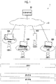
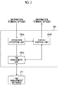
- Fig. 1 is a diagram for describing a summary of a cloud system 1 that provides a service for a workspace.
- the workspace in the present exemplary embodiment is used for temporarily storing a document of work in progress.
- the cloud system 1 is configured with a cloud server 20 that is connected to a network 10, and an information terminal that is used for accessing the cloud server 20 by a user who uses the service.
- the cloud server 20 in the present exemplary embodiment is an example of an information processing system.
- a "user A” and a “user B” are illustrated as individual users, and a "group AA” and a “group BB” are illustrated as users (hereinafter, referred to as a "group user") of a group configured with a plurality of users.
- the workspace is managed in units of users or group users .
- a desktop computer 30A used at an office a laptop computer 30B used at a satellite office, a smartphone 30C used in, for example, an outdoor space during movement, and a laptop computer 30D used at home are illustrated as an example of the information terminal used for accessing the cloud server 20 by the user A.
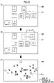
- Figs. 2A and 2B are diagrams for describing a relationship between the entire workspace and a work screen.
- Fig. 2A illustrates a relationship between the entire workspace and a range displayed on the information terminal
- Fig. 2B illustrates an example of the work screen displayed on the information terminal.
- the workspace is used as a virtual workbench dedicated to the user. Thus, a method of using the workspace depends on the user.
- Icons corresponding to files are arranged on the workspace.
- the files include, for example, a data file and a program file.
- the icons corresponding to the files include a thumbnail in which an image of a head page or a representative page of a document is reduced, a thumbnail of a photograph, a thumbnail in which an image of a head frame or a representative frame of a video film is reduced, a design or a text representing a type of document, a design or a text representing an app, a tray or a folder indicating a storage location of the document or the like, and the like.
- the icons can be arranged at any locations in the workspace.
- the "one collection” refers to a state where a collection that can be distinguished from others is formed. For example, in the workspace illustrated in Fig. 2A , a plurality of collections are formed.
- the icons can be arranged at any location designated by the user on the workspace illustrated in Fig. 2A .
- one icon can be arranged to be overlaid on another icon.
- "overlaid” includes not only a case of partial overlaying but also a case of overlaying of the entirety.
- Such display is because in a case where the number of icons managed in the workspace is large, displaying the entire workspace on a display of the information terminal excessively increases a scale ratio, and contents of the icons are not easily identified.
- a range in which the contents of the icons can be identified is cut out from the workspace and displayed on the work screen of the information terminal.
- a scale that defines the range in which the contents of the icons can be identified is predetermined based on initial setting.
- a display magnification of the workspace displayed on the work screen may be variable based on an instruction of the user for the work screen. Seven icons are displayed on the work screen illustrated in Fig. 2B .
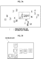
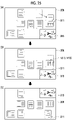
- Figs. 3A and 3B are diagrams for describing a hardware configuration example of the cloud server 20 used in Exemplary Embodiment 1.
- Fig. 3A illustrates an example of a hardware configuration
- Fig. 3B illustrates a structure example of data stored in an auxiliary storage device 204.
- the cloud server 20 illustrated in Fig. 3A includes a processor 201 that controls an operation of the entire apparatus, a read only memory (ROM) 202 that stores a basic input output system (BIOS) or the like, a random access memory (RAM) 203 that is used as a work area of the processor 201, the auxiliary storage device 204 that stores data such as a program, and a communication interface (IF) 205 that is used for external communication.
- the processor 201 is connected to each unit through a signal line 206 such as a bus.
- the processor 201, the ROM 202, and the RAM 203 function as a so-called computer.
- the processor 201 implements various functions through execution of the program.
- the processor 201 implements a service for providing the workspace through execution of the program.
- auxiliary storage device 204 semiconductor memory or a hard disk device is used in the auxiliary storage device 204.
- the program and data related to the workspace are stored in the auxiliary storage device 204.
- the program includes an operation system and an app for the workspace.
- the auxiliary storage device 204 stores a file management database 211 as the data related to the workspace.
- the file management database 211 stores management data 211A, 211B, 211AA, and 211BB for each user.
- the management data 211A is for the user A
- the management data 211B is for the user B
- the management data 211AA is for the group user AA
- the management data 211BB is for the group user BB.
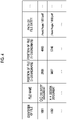
- Fig. 4 is a diagram illustrating a data example of the file management database 211. In Fig. 4 , a part of fields constituting the file management database 211 are represented.
- an "identifier of file”, a "file name”, a “position of file”, and a “path of file entity” are represented in a meaning of a file corresponding to an icon.
- the "position of file” is provided as coordinates on the workspace.
- the "position of file” is represented by an X coordinate and a Y coordinate.
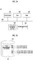
- Fig. 5 is a diagram for describing a functional configuration example of the cloud server 20 used in Exemplary Embodiment 1.
- a functional configuration illustrated in Fig. 5 is implemented through execution of the app by the processor 201.
- an operation detection unit 201A, a display control unit 201B, and a file management unit 201C are represented as functions related to the workspace.
- the operation detection unit 201A detects an operation (hereinafter, referred to as "drag") of moving a position of an icon on the workspace through an operation performed on the work screen of the information terminal.
- an instruction from the information terminal operated by the user is not limited to the drag.
- the operation detection unit 201A also detects an operation of changing a range of the workspace displayed on the work screen or changing the display magnification.
- the operation detection unit 201A in the present exemplary embodiment also acquires the position of the icon being dragged, a speed of the drag, and a direction of the drag.
- the operation detection unit 201A detects an operation of the user performed on a symbol for changing a scale of the workspace displayed on the work screen.
- the scale is an example of the display magnification.
- the operation detection unit 201A changes the scale of the workspace.
- the symbol includes a symbol for reduction and a symbol for enlargement.
- the symbol is an example of an "operator" used for changing the display magnification.
- the operation detection unit 201A detects an operation (hereinafter, referred to as "drop") of finishing the drag of the icon on the workspace.
- the display control unit 201B controls generation of the work screen displayed on the information terminal operated by the user.
- the work screen generated by the display control unit 201B is transmitted to the information terminal of the corresponding user.
- the display control unit 201B also has a function of changing the scale of the workspace displayed on the work screen in accordance with the position of the icon being dragged, the speed of the drag, and the direction of the drag.
- the display control unit 201B controls display of the symbol for changing the scale on the work screen and movement of the symbol on the work screen in accordance with the position of the icon being dragged, the speed of the drag, and the direction of the drag.
- the file management unit 201C manages a position at which the icon is dropped on the workspace, as the "position of file” in the file management database 211.
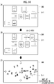
- Fig. 6 is a diagram for describing a hardware configuration example of the information terminal used in Exemplary Embodiment 1.
- a hardware configuration of the desktop computer 30A used at the office is illustrated.
- the computer 30A illustrated in Fig. 6 includes a processor 301 that controls an operation of the entire apparatus, a ROM 302 that stores a BIOS or the like, a RAM 303 that is used as a work area of the processor 301, an auxiliary storage device 304 that stores data such as a program, an operation reception device 305 that receives an operation of the user, a display 306 that displays information about the workspace on the work screen, and a communication interface (IF) 307 that is used for external communication.
- the processor 301 is connected to each unit through a signal line 308 such as a bus.
- the processor 301, the ROM 302, and the RAM 303 function as a so-called computer.
- the processor 301 implements various functions through execution of the program.
- the processor 301 provides a service for the workspace through execution of the program.
- auxiliary storage device 304 semiconductor memory or a hard disk device is used in the auxiliary storage device 304.
- the program and the like are stored in the auxiliary storage device 304.
- the program includes an operation system.
- a keyboard or a mouse is used in the operation reception device 305.
- the display 306 is, for example, a liquid crystal display or an organic EL display and is used for displaying the workspace.
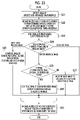
- Fig. 7 is a flowchart for describing an example of a processing operation performed by the cloud server 20 (refer to Fig. 1 ) in Exemplary Embodiment 1.
- Symbol S in Fig. 7 denotes a step.
- the processing operation illustrated in Fig. 7 is started in a state where the information about the workspace is displayed on the information terminal.
- the processor 201 detects drag of a specific icon arranged on the workspace (step S1).
- step S2 the processor 201 starts reduced display of the workspace.
- the reduced display of the workspace is not executed in response to the drag of the icon that does not correspond to the specific operation.
- the specific operation is such that a distance of the drag is greater than or equal to a predetermined distance, the speed of the drag is greater than or equal to a predetermined speed, another icon is present in the direction of the drag, or a distance between the icon of a target of the drag and an end portion of the display is less than a predetermined distance.
- the processor 201 In a case where the processor 201 detects drop of the icon on the workspace (step S3), the processor 201 records information about a position at which the icon is dropped, in the file management database 211 (step S4).
- Fig. 8 is a diagram for describing an example of the reduced display of the workspace in a case where a distance L1 of drag is greater than or equal to a predetermined distance LT1.
- A illustrates a display screen at a point in time of a start of the drag
- B illustrates the display screen immediately before a start of the reduced display
- C illustrates the display screen after the reduced display;
- a starting point of the distance L1 is the position of the icon before the start of the drag.
- the distance L1 may be a straight distance between the starting point and a current position of the icon being dragged, or may be a distance along a path of the drag.
- the direction of the drag is a right end side of the display 306.
- the distance L1 of the drag is greater than or equal to the predetermined distance LT1.
- the processor 201 determines that the specific operation is executed, and starts the reduced display.
- reduction of the display magnification is represented by reduction of sizes of the icons displayed on the work screen and an increase in number of displayed icons.
- the user during the drag can find a location at which the drop is to be performed.
- the processor 201 controls a speed of reduction of a display size of the workspace displayed on the display 306 to be greater than the speed of the drag of the icon on the display 306.
- Fig. 9 is a diagram for describing an example of the reduced display of the workspace in a case where a distance L2 between the icon of the target of the drag and the end portion of the display 306 is less than a predetermined distance LT2.
- (A) illustrates the display screen at the point in time of the start of the drag
- (B) illustrates the display screen immediately before the start of the reduced display
- (C) illustrates the display screen after the reduced display.
- the processor 201 determines that the specific operation is executed, and starts the reduced display.
- the processor 201 executes the reduced display of the workspace.
- the reduced display of the workspace may be started in a case where the icon is being dragged.
- a speed of reduction in a case where the icon being dragged is positioned near the center of the display 306 or the work screen may be less than the speed of reduction in a case where the icon being dragged is positioned in an outer edge portion of the display 306 or an outer edge portion of the work screen.
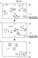
- Fig. 10 is a diagram for describing an example of the reduced display of the workspace in a case where a speed V1 of the drag is greater than or equal to a predetermined speed VT1.
- A illustrates the display screen at the point in time of the start of the drag
- B illustrates the display screen immediately before the start of the reduced display
- C illustrates the display screen after the reduced display.
- the direction of the drag is the right end side of the display 306.
- the speed V1 of the drag is greater than or equal to the predetermined speed VT1.
- the speed V1 of the drag is defined as a speed in a workflow.
- the speed V1 may be defined as a speed on the display 306.
- the processor 201 determines that the specific operation is executed, and starts the reduced display.
- Fig. 11 is a diagram for describing an example of the reduced display of the workspace in a case where another icon is present in the direction of the drag.
- (A) illustrates the display screen at the point in time of the start of the drag
- (B) illustrates the display screen after the reduced display in a case where the other icon is present in the direction of the drag.
- FIG. 11 In (A) of Fig. 11 , the cursor 311 is moved onto the icon of the target of the drag, and the drag is started.
- a case of (B) of Fig. 11 is a case where the other icon is present in a right direction of the display 306 on the workspace.
- the processor 201 determines that the specific operation is executed, and starts the reduced display.
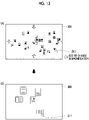
- Fig. 12 is a diagram for describing an example of the reduced display of the workspace in a case where the other icon is not present in the direction of the drag.
- (A) illustrates the display screen at the point in time of the start of the drag
- (B) illustrates the display screen in a case where the other icon is not present in the direction of the drag.
- Fig. 13 is a diagram for describing an example of a change in display magnification of the workspace in a case where the icon being dragged stops at a specific position, or a case where the icon is dropped.
- (A) illustrates a display example during the drag
- (B) illustrates a display example in a case where, for example, the icon stops at the specific position.
- the change in display magnification illustrated in Example 5 is used in combination with Example 1 to Example 4.
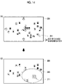
- Fig. 14 is a diagram for describing another example of the change in display magnification of the workspace in a case where the icon being dragged stops at the specific position.
- (A) illustrates a display example during the drag
- (B) illustrates a display example in a case where, for example, the icon stops at the specific position.
- the change in display magnification illustrated in Example 6 is also used in combination with Example 1 to Example 4.
- Fig. 15 is a diagram for describing another example of the reduced display in a case where the drag of the icon corresponds to the specific operation.
- (A) illustrates the display screen at the point in time of the start of the drag
- (B) illustrates the display screen after switching to a magnification at which the entire workspace is displayed on the display 306.
- Example 1 While an example in which display of the workspace displayed on the display 306 is gradually reduced is described in a case of Example 1 to Example 4, the display magnification is switched at once in the present example.
- the cursor 311 While a position of the cursor 311 is forcibly changed, the cursor 311 is positioned near the center of the display 306. Thus, the distance of the drag is decreased even in a case of dragging the icon in any direction.
- a configuration of the cloud system 1 (refer to Fig. 1 ) described in Exemplary Embodiment 2 is the same as Exemplary Embodiment 1.
- a configuration of the cloud server 20 (refer to Fig. 1 ) that provides the service for the workspace is the same as Exemplary Embodiment 1.
- Fig. 16 is a flowchart for describing an example of a processing operation performed by the cloud server 20 (refer to Fig. 1 ) in Exemplary Embodiment 2.
- the processor 201 detects the drag of the specific icon arranged on the workspace (step S11).
- the processor 201 displays the symbol for reduction and the symbol for enlargement on the workspace (step S12).
- step S13 the processor 201 loops steps S14 to S18 (step S13).
- the processor 201 determines whether or not the icon is dragged onto a symbol (step S14).
- determination results in three ways.
- the processor 201 determines whether or not a distance between the icon being dragged and the symbol is greater than or equal to a threshold value (step S15).
- the processor 201 obtains a negative result in step S15 and returns to step S13.
- the processor 201 obtains a positive result in step S15 and moves the symbol such that the distance is less than the threshold value (step S18) .
- This movement of the symbol means that the symbol follows the drag of the icon. During the drag, the distance between the symbol and the icon is maintained at the threshold value in step S15.
- step S14 in a case where a determination that the icon is dragged onto the symbol for reduction is made, the processor 201 reduces the entire workspace while the icon is present on the symbol for reduction (step S16). Then, the processor 201 returns to step S13.
- step S14 while the icon is present on the symbol for enlargement, the entire workspace is enlarged (step S17). Then, the processor 201 returns to step S13.
- a position at which the drop is performed is recorded in the file management database 211 (step S19).
- the display magnification of the workspace displayed on the display 306 can be adjusted based on an instruction of the user.
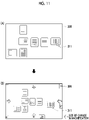
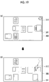
- Fig. 17 is a diagram for describing an example of displaying only a symbol for reduction 312 in a case where the drag of the icon is detected.
- (A) illustrates the display screen at the point in time of the start of the drag
- (B) illustrates a state where the symbol for reduction 312 is displayed on the display 306 as a result of detecting the drag of the icon performed using the cursor 311.
- Fig. 18 is a diagram for describing the reduced display of the workspace using the symbol for reduction 312.
- (A) illustrates a state where the icon is overlaid on the symbol for reduction 312
- (B) illustrates a state where the reduced display of the workspace continues.
- the reduced display of the workspace is started at a sign of overlaying of the icon on the symbol for reduction 312.
- the workspace is reduced in a direction toward the center of the display 306.
- the part not displayed gradually appears on the display 306.
- the reduced display of the workspace continues while the icon is overlaid on the symbol for reduction 312.
- Fig. 19 is a diagram for describing following of the symbol for reduction 312 in a case where the icon is dragged in a direction of separating from the symbol for reduction 312.
- (A) illustrates the drag of the icon in a state where the symbol for reduction 312 is displayed
- (B) illustrates a state of following of the symbol for reduction 312 in the drag direction of the icon.
- the position of the icon in (B) of Fig. 19 moves in a lower-left direction of the display 306 with respect to the position of the icon in (A) of Fig. 19 .
- the symbol for reduction 312 moves in the lower-left direction of the display 306 in a state where a constant distance to the icon being dragged is maintained. That is, the symbol for reduction 312 follows the icon being dragged.
- the icon can be overlaid on the symbol for reduction 312 by slightly returning the icon in a direction opposite to the drag direction. In a case where the icon is overlaid on the symbol for reduction 312, the reduced display of the workspace is started.
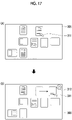
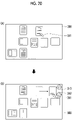
- Fig. 20 is a diagram for describing an example in which both of the symbol for reduction 312 and a symbol for enlargement 313 are displayed in a case where the drag of the icon is detected.
- (A) illustrates the display screen at the point in time of the start of the drag
- (B) illustrates a state where the symbol for reduction 312 and the symbol for enlargement 313 are displayed on the display 306 as a result of detecting the drag of the icon performed using the cursor 311.
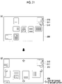
- Fig. 21 is a diagram for describing enlarged display of the workspace using the symbol for enlargement 313.
- (A) illustrates a state where the icon is overlaid on the symbol for enlargement 313, and (B) illustrates a state where the enlarged display of the workspace continues.
- the enlarged display of the workspace is started at a sign of overlaying of the icon on the symbol for enlargement 313.
- an image corresponding to the workspace is enlarged outward from the center of the display 306, and arrangement of other icons present around the drag destination of the icon is easily perceived.
- the enlarged display of the workspace continues while the icon is overlaid on the symbol for enlargement 313.
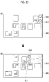
- Fig. 22 is a diagram for describing following of the two symbols 312 and 313 in a case where the icon is dragged in a direction of separating from the symbol for reduction 312 and the symbol for enlargement 313.
- (A) illustrates the drag of the icon in a state where the two symbols 312 and 313 are displayed
- (B) illustrates a state of following of the two symbols 312 and 313 in the drag direction of the icon.
- the icon in (B) of Fig. 22 moves in a left direction of the display 306 from the position of the icon in (A) of Fig. 22 as a starting point. Along with this movement, the symbol for reduction 312 and the symbol for enlargement 313 also follow the icon being dragged, at a constant distance.
- the icon can be overlaid on the symbol for reduction 312 or the symbol for enlargement 313 by slightly returning the icon in the direction opposite to the drag direction. In a case where the icon is overlaid on the symbol for enlargement 313, the enlarged display of the workspace is started.
- a configuration of the cloud system 1 (refer to Fig. 1 ) described in Exemplary Embodiment 3 is the same as Exemplary Embodiment 1.
- a configuration of the cloud server 20 (refer to Fig. 1 ) that provides the service for the workspace is the same as Exemplary Embodiment 1.
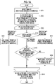
- Fig. 23 is a flowchart for describing an example of a processing operation performed by the cloud server 20 (refer to Fig. 1 ) in Exemplary Embodiment 3.
- the processor 201 detects the drag of the specific icon arranged on the workspace (step S21) .
- the processor 201 displays a reduced image of the entire workspace in a separate frame on the display 306 (step S22).
- step S23 the processor 201 loops steps S24 to S28 (step S23).
- the processor 201 determines whether or not the icon passes through a frame line of the reduced image (step S24).
- determination results in three ways.
- the processor 201 repeats the determination in step S24.
- the processor 201 determines whether or not a speed V2 of the drag is greater than or equal to a threshold value VT2 (step S25).
- step S25 the processor 201 obtains a positive result in step S25 and continues the drag of the icon on the reduced image (step S26). The reduced display of the icon being dragged is also performed on the reduced image. Then, the processor 201 returns to step S23.
- the processor 201 obtains a negative result in step S25 and moves the reduced image to a location in other than the direction of the drag (step S27) . Then, the processor 201 returns to step S23.
- step S24 in a case where a determination that the icon exits from the reduced image is made, the processor 201 continues the drag of the icon on the workspace outside the reduced image (step S28). The processor 201 restores a size of the icon being dragged. Then, the processor 201 returns to step S23.
- the processor 201 In a case where the processor 201 detects the drop of the icon, the processor 201 records the position at which the drop is performed, in the file management database 211 (step S29) .
- Fig. 24 is a diagram for describing an example in which the superimposed display of a reduced image 315 representing the entire workspace is performed on the display 306 (refer to Fig. 6 ) in a case where the drag of the icon is detected.
- (A) illustrates the display screen at the point in time of the start of the drag
- (B) illustrates a case where the icon enters the reduced image 315 at the speed V2 greater than or equal to the threshold value VT2
- (C) illustrates the drag of the icon within the reduced image 315.
- the display magnification of the workspace being displayed does not change . In other words, the reduced display of the workspace is not performed.
- a position of display is not limited to the lower-right corner.
- the position at which the reduced image 315 is displayed may be predetermined.
- the reduced image 315 may be present ahead in the direction of the drag of the icon.
- the reduced image 315 is appropriate for perceiving the entire workspace. Thus, by dragging the icon onto the reduced image 315, a time period required for dragging the icon to a target location is shortened, compared to a case of dragging the icon outside the reduced image 315.
- the superimposed display of the reduced image 315 is stopped. At this point, information about a surrounding area of a location at which the icon is dropped, or a location at which the icon is stopped may be displayed on the display 306.
- a content that is displayed in real dimensions on the display 306 as a background of the reduced image 315 subjected to the superimposed display may be changed following the drag of the icon within the reduced image 315.
- Fig. 25 is a diagram for describing another example in which the superimposed display of the reduced image 315 representing the entire workspace is performed on the display 306 (refer to Fig. 6 ) in a case where the drag of the icon is detected.
- (A) illustrates the display screen at the point in time of the start of the drag
- (B) illustrates a case where the icon enters the reduced image 315 at the speed V2 less than the threshold value VT2
- (C) illustrates a state where a position of the reduced image 315 is moved to a position at which the icon is avoided.
- the icon does not penetrate into the reduced image 315, and movement of the icon within a space displayed as the background of the reduced image 315 continues.
- the reduced image 315 is retracted to a location in other than the direction of the drag of the icon such that visual recognition of a space in which the icon is dragged is not impeded.
- the reduced image 315 is moved to an upper-right corner of the display 306.
- the upper-right corner of the display 306 is on a side opposite to the direction of the drag of the icon.
- the reduced image 315 after movement does not impede the drag of the icon.
- a movement destination of the reduced image 315 may be an upper-left corner or a lower-left corner of the display 306 or other locations.
- the superimposed display of the reduced image 315 may be executed in a case where the display size of the workspace displayed on the display 306 becomes smaller than a size of the display 306.
- Fig. 26 is a diagram for describing an example of a change in display magnification of the workspace in a case where the display size of the workspace displayed on the display 306 becomes smaller than the size of the display 306.
- (A) illustrates a display example during the drag
- (B) illustrates a state where the entire workspace displayed on the display 306 is reduced
- (C) illustrates a state where a combined screen of an image at the display magnification before the start of the reduced display and the reduced image 315 is displayed.
- the reduced display of the workspace is not executed in response to the drag of the icon that does not correspond to the specific operation.
- the reduced display of the workspace displayed on the work screen may be executed on a condition that the drag of the icon is detected.
- the service for the workspace is provided through the cloud server 20 (refer to Fig. 1 ) is described.
- the service is not limited to a service on a cloud.
- the workspace may be provided as a function on a server that is provided on a local area network (LAN).
- LAN local area network
- a function of the workspace may be provided as a function of the program that operates on the computers 30A, 30B, and 30D (refer to Fig. 1 ) and the smartphone 30C (refer to Fig. 1 ) operated by the user.
- the program may be any of the operation system, firmware, and the application program.
- the computers 30A, 30B, and 30D and the smartphone 30C are an example of the information processing system.
- the icons corresponding to the files can be arranged at any locations in the workspace, and one icon can be overlaid on another icon. However, only one icon may be arrangeable on one section arranged in a lattice form, as in a so-called desktop screen or a home screen.
- the workspace is not limited to the temporary storage location of the document, and the document does not need to be a work in progress.
- processor refers to hardware in a broad sense.
- the processor include general processors (e.g., CPU: Central Processing Unit) and dedicated processors (e.g., GPU: Graphics Processing Unit, ASIC: Application Specific Integrated Circuit, FPGA: Field Programmable Gate Array, and programmable logic device).
- general processors e.g., CPU: Central Processing Unit
- dedicated processors e.g., GPU: Graphics Processing Unit
- ASIC Application Specific Integrated Circuit
- FPGA Field Programmable Gate Array
- programmable logic device e.g., programmable logic device
Landscapes
- Engineering & Computer Science (AREA)
- General Engineering & Computer Science (AREA)
- Theoretical Computer Science (AREA)
- Human Computer Interaction (AREA)
- Physics & Mathematics (AREA)
- General Physics & Mathematics (AREA)
- User Interface Of Digital Computer (AREA)
Applications Claiming Priority (1)
| Application Number | Priority Date | Filing Date | Title |
|---|---|---|---|
| JP2021054218A JP7651904B2 (ja) | 2021-03-26 | 2021-03-26 | 情報処理システム |
Publications (1)
| Publication Number | Publication Date |
|---|---|
| EP4064013A1 true EP4064013A1 (de) | 2022-09-28 |
Family
ID=77595357
Family Applications (1)
| Application Number | Title | Priority Date | Filing Date |
|---|---|---|---|
| EP21194208.1A Withdrawn EP4064013A1 (de) | 2021-03-26 | 2021-09-01 | Informationsverarbeitungssystem, programm und informationsverarbeitungsverfahren |
Country Status (4)
| Country | Link |
|---|---|
| US (1) | US20220308740A1 (de) |
| EP (1) | EP4064013A1 (de) |
| JP (1) | JP7651904B2 (de) |
| CN (1) | CN115202532A (de) |
Families Citing this family (2)
| Publication number | Priority date | Publication date | Assignee | Title |
|---|---|---|---|---|
| US11714928B2 (en) * | 2020-02-27 | 2023-08-01 | Maxon Computer Gmbh | Systems and methods for a self-adjusting node workspace |
| JP7658083B2 (ja) * | 2020-12-22 | 2025-04-08 | 富士フイルムビジネスイノベーション株式会社 | 情報処理装置及び情報処理プログラム |
Citations (5)
| Publication number | Priority date | Publication date | Assignee | Title |
|---|---|---|---|---|
| JPS6217318B2 (de) | 1980-06-13 | 1987-04-16 | Matsushita Electric Ind Co Ltd | |
| US6052110A (en) * | 1998-05-11 | 2000-04-18 | Sony Corporation | Dynamic control of zoom operation in computer graphics |
| EP2397936A2 (de) * | 2010-06-17 | 2011-12-21 | LG ELectronics INC. | Mobiles Endgerät und Ansteuerungsverfahren dafür |
| US20130132895A1 (en) * | 2011-11-17 | 2013-05-23 | Prezi, Inc. | Grouping with frames to transform display elements within a zooming user interface |
| US20160170608A1 (en) * | 2013-09-03 | 2016-06-16 | Apple Inc. | User interface for manipulating user interface objects |
Family Cites Families (17)
| Publication number | Priority date | Publication date | Assignee | Title |
|---|---|---|---|---|
| US6628304B2 (en) * | 1998-12-09 | 2003-09-30 | Cisco Technology, Inc. | Method and apparatus providing a graphical user interface for representing and navigating hierarchical networks |
| EP1725927A4 (de) * | 2004-02-23 | 2007-12-26 | Hillcrest Lab Inc | Verfahren zum inkrementellen echtzeit-zoomen |
| US20090027421A1 (en) * | 2007-07-27 | 2009-01-29 | Franklin Servan-Schreiber | Computer system with a zooming capability and method |
| US8082518B2 (en) * | 2008-08-29 | 2011-12-20 | Microsoft Corporation | Scrollable area multi-scale viewing |
| JP5751608B2 (ja) * | 2010-02-05 | 2015-07-22 | 日本電気株式会社 | ズーム処理装置、ズーム処理方法、及びコンピュータプログラム |
| JP5494337B2 (ja) * | 2010-07-30 | 2014-05-14 | ソニー株式会社 | 情報処理装置、情報処理方法及び情報処理プログラム |
| JP5722642B2 (ja) | 2011-01-24 | 2015-05-27 | 京セラ株式会社 | 携帯端末装置 |
| US20130057587A1 (en) | 2011-09-01 | 2013-03-07 | Microsoft Corporation | Arranging tiles |
| US20140258903A1 (en) | 2011-09-28 | 2014-09-11 | Sharp Kabushiki Kaisha | Display device and display method for enhancing visibility |
| JP5999830B2 (ja) * | 2011-10-28 | 2016-09-28 | 任天堂株式会社 | 情報処理プログラム、情報処理装置、情報処理システム、および、情報処理方法 |
| US20130132867A1 (en) * | 2011-11-21 | 2013-05-23 | Bradley Edward Morris | Systems and Methods for Image Navigation Using Zoom Operations |
| KR101955979B1 (ko) | 2012-09-04 | 2019-03-08 | 엘지전자 주식회사 | 이동 단말기 및 그의 어플리케이션 아이콘 이동 방법 |
| JP2014071724A (ja) | 2012-09-28 | 2014-04-21 | Kyocera Corp | 電子機器、制御方法及び制御プログラム |
| JP6179353B2 (ja) | 2013-10-31 | 2017-08-16 | 富士ゼロックス株式会社 | ファイル管理装置及びプログラム |
| JP7043804B2 (ja) | 2017-11-22 | 2022-03-30 | コニカミノルタ株式会社 | 情報処理装置、情報処理装置の制御方法、およびプログラム |
| US11416130B2 (en) * | 2019-10-01 | 2022-08-16 | Microsoft Technology Licensing, Llc | Moving applications on multi-screen computing device |
| CN114253433B (zh) * | 2020-09-24 | 2024-09-24 | 荣耀终端有限公司 | 一种动态元素控制方法、电子设备和计算机可读存储介质 |
-
2021
- 2021-03-26 JP JP2021054218A patent/JP7651904B2/ja active Active
- 2021-07-30 US US17/389,375 patent/US20220308740A1/en not_active Abandoned
- 2021-09-01 EP EP21194208.1A patent/EP4064013A1/de not_active Withdrawn
- 2021-09-02 CN CN202111026118.8A patent/CN115202532A/zh active Pending
Patent Citations (5)
| Publication number | Priority date | Publication date | Assignee | Title |
|---|---|---|---|---|
| JPS6217318B2 (de) | 1980-06-13 | 1987-04-16 | Matsushita Electric Ind Co Ltd | |
| US6052110A (en) * | 1998-05-11 | 2000-04-18 | Sony Corporation | Dynamic control of zoom operation in computer graphics |
| EP2397936A2 (de) * | 2010-06-17 | 2011-12-21 | LG ELectronics INC. | Mobiles Endgerät und Ansteuerungsverfahren dafür |
| US20130132895A1 (en) * | 2011-11-17 | 2013-05-23 | Prezi, Inc. | Grouping with frames to transform display elements within a zooming user interface |
| US20160170608A1 (en) * | 2013-09-03 | 2016-06-16 | Apple Inc. | User interface for manipulating user interface objects |
Non-Patent Citations (1)
| Title |
|---|
| ANDREWS CHRISTOPHER ET AL: "The Impact of Physical Navigation on Spatial Organization for Sensemaking", IEEE TRANSACTIONS ON VISUALIZATION AND COMPUTER GRAPHICS, IEEE, USA, vol. 19, no. 12, 1 December 2013 (2013-12-01), pages 2207 - 2216, XP011529753, ISSN: 1077-2626, [retrieved on 20131016], DOI: 10.1109/TVCG.2013.205 * |
Also Published As
| Publication number | Publication date |
|---|---|
| JP2022151240A (ja) | 2022-10-07 |
| US20220308740A1 (en) | 2022-09-29 |
| JP7651904B2 (ja) | 2025-03-27 |
| CN115202532A (zh) | 2022-10-18 |
Similar Documents
| Publication | Publication Date | Title |
|---|---|---|
| KR102024422B1 (ko) | 파일 폴더 내의 파일을 오픈하기 위한 방법 및 단말기 | |
| US9092121B2 (en) | Copy and paste experience | |
| US8683377B2 (en) | Method for dynamically modifying zoom level to facilitate navigation on a graphical user interface | |
| US8892997B2 (en) | Overflow stack user interface | |
| US10627990B2 (en) | Map information display device, map information display method, and map information display program | |
| US20090019385A1 (en) | Management of Icons in a Display Interface | |
| EP3155507B1 (de) | Speichersystembenutzerschnittstelle mit umlaufdateiensammlung | |
| US9747010B2 (en) | Electronic content visual comparison apparatus and method | |
| US20090040240A1 (en) | Hovering table headers | |
| EP2521025B1 (de) | Verfahren und benutzervorrichtung zur komponentenanzeige | |
| CN105094592A (zh) | 内容显示装置、内容显示方法及程序 | |
| EP2778880B1 (de) | Verfahren zur Steuerung der Anzeigefunktion und elektronische Vorrichtung dafür | |
| EP2959370A1 (de) | Verfahren und vorrichtung für zweidimensionale dokumentennavigation | |
| US20150324068A1 (en) | User interface structure (uis) for geographic information system applications | |
| US10048829B2 (en) | Method for displaying icons and electronic apparatus | |
| KR20160086842A (ko) | 디스플레이 콘텐츠의 리사이징 기법 | |
| CN111638823A (zh) | 应用图标显示方法、装置及电子设备 | |
| EP4064013A1 (de) | Informationsverarbeitungssystem, programm und informationsverarbeitungsverfahren | |
| CN111143731A (zh) | 一种网页界面缩放时的显示方法、装置及终端设备 | |
| CN113296661A (zh) | 图像处理方法、装置、电子设备及可读存储介质 | |
| DE102017102691B4 (de) | Ausführen von Aktionen in Erwiderung auf ein Schweben über einer Eingabeoberfläche | |
| US20180088785A1 (en) | Navigating a set of selectable items in a user interface | |
| CN113986076A (zh) | 图标显示控制方法、装置、电子设备及存储介质 | |
| KR102371098B1 (ko) | 오브젝트를 편집 가능한 형태로 전체 화면 팝 아웃하는 기법 | |
| US11157130B2 (en) | Cursor-based resizing for copied image portions |
Legal Events
| Date | Code | Title | Description |
|---|---|---|---|
| PUAI | Public reference made under article 153(3) epc to a published international application that has entered the european phase |
Free format text: ORIGINAL CODE: 0009012 |
|
| STAA | Information on the status of an ep patent application or granted ep patent |
Free format text: STATUS: REQUEST FOR EXAMINATION WAS MADE |
|
| 17P | Request for examination filed |
Effective date: 20210901 |
|
| AK | Designated contracting states |
Kind code of ref document: A1 Designated state(s): AL AT BE BG CH CY CZ DE DK EE ES FI FR GB GR HR HU IE IS IT LI LT LU LV MC MK MT NL NO PL PT RO RS SE SI SK SM TR |
|
| RBV | Designated contracting states (corrected) |
Designated state(s): AL AT BE BG CH CY CZ DE DK EE ES FI FR GB GR HR HU IE IS IT LI LT LU LV MC MK MT NL NO PL PT RO RS SE SI SK SM TR |
|
| STAA | Information on the status of an ep patent application or granted ep patent |
Free format text: STATUS: EXAMINATION IS IN PROGRESS |
|
| 17Q | First examination report despatched |
Effective date: 20250221 |
|
| STAA | Information on the status of an ep patent application or granted ep patent |
Free format text: STATUS: THE APPLICATION HAS BEEN WITHDRAWN |
|
| 18W | Application withdrawn |
Effective date: 20250522 |