EP4063989B1 - Kombinationsregler für kryogene behälter - Google Patents
Kombinationsregler für kryogene behälter Download PDFInfo
- Publication number
- EP4063989B1 EP4063989B1 EP22159204.1A EP22159204A EP4063989B1 EP 4063989 B1 EP4063989 B1 EP 4063989B1 EP 22159204 A EP22159204 A EP 22159204A EP 4063989 B1 EP4063989 B1 EP 4063989B1
- Authority
- EP
- European Patent Office
- Prior art keywords
- regulator
- pressure regulator
- pressure
- port
- outlet port
- Prior art date
- Legal status (The legal status is an assumption and is not a legal conclusion. Google has not performed a legal analysis and makes no representation as to the accuracy of the status listed.)
- Active
Links
Images



Classifications
-
- F—MECHANICAL ENGINEERING; LIGHTING; HEATING; WEAPONS; BLASTING
- F17—STORING OR DISTRIBUTING GASES OR LIQUIDS
- F17C—VESSELS FOR CONTAINING OR STORING COMPRESSED, LIQUEFIED OR SOLIDIFIED GASES; FIXED-CAPACITY GAS-HOLDERS; FILLING VESSELS WITH, OR DISCHARGING FROM VESSELS, COMPRESSED, LIQUEFIED, OR SOLIDIFIED GASES
- F17C13/00—Details of vessels or of the filling or discharging of vessels
- F17C13/04—Arrangement or mounting of valves
-
- F—MECHANICAL ENGINEERING; LIGHTING; HEATING; WEAPONS; BLASTING
- F16—ENGINEERING ELEMENTS AND UNITS; GENERAL MEASURES FOR PRODUCING AND MAINTAINING EFFECTIVE FUNCTIONING OF MACHINES OR INSTALLATIONS; THERMAL INSULATION IN GENERAL
- F16K—VALVES; TAPS; COCKS; ACTUATING-FLOATS; DEVICES FOR VENTING OR AERATING
- F16K17/00—Safety valves; Equalising valves, e.g. pressure relief valves
- F16K17/02—Safety valves; Equalising valves, e.g. pressure relief valves opening on surplus pressure on one side; closing on insufficient pressure on one side
- F16K17/04—Safety valves; Equalising valves, e.g. pressure relief valves opening on surplus pressure on one side; closing on insufficient pressure on one side spring-loaded
- F16K17/0446—Safety valves; Equalising valves, e.g. pressure relief valves opening on surplus pressure on one side; closing on insufficient pressure on one side spring-loaded with an obturating member having at least a component of their opening and closing motion not perpendicular to the closing faces
- F16K17/0453—Safety valves; Equalising valves, e.g. pressure relief valves opening on surplus pressure on one side; closing on insufficient pressure on one side spring-loaded with an obturating member having at least a component of their opening and closing motion not perpendicular to the closing faces the member being a diaphragm
-
- G—PHYSICS
- G05—CONTROLLING; REGULATING
- G05D—SYSTEMS FOR CONTROLLING OR REGULATING NON-ELECTRIC VARIABLES
- G05D16/00—Control of fluid pressure
- G05D16/04—Control of fluid pressure without auxiliary power
- G05D16/0402—Control of fluid pressure without auxiliary power with two or more controllers mounted in series
-
- F—MECHANICAL ENGINEERING; LIGHTING; HEATING; WEAPONS; BLASTING
- F16—ENGINEERING ELEMENTS AND UNITS; GENERAL MEASURES FOR PRODUCING AND MAINTAINING EFFECTIVE FUNCTIONING OF MACHINES OR INSTALLATIONS; THERMAL INSULATION IN GENERAL
- F16K—VALVES; TAPS; COCKS; ACTUATING-FLOATS; DEVICES FOR VENTING OR AERATING
- F16K11/00—Multiple-way valves, e.g. mixing valves; Pipe fittings incorporating such valves
- F16K11/10—Multiple-way valves, e.g. mixing valves; Pipe fittings incorporating such valves with two or more closure members not moving as a unit
- F16K11/20—Multiple-way valves, e.g. mixing valves; Pipe fittings incorporating such valves with two or more closure members not moving as a unit operated by separate actuating members
- F16K11/22—Multiple-way valves, e.g. mixing valves; Pipe fittings incorporating such valves with two or more closure members not moving as a unit operated by separate actuating members with an actuating member for each valve, e.g. interconnected to form multiple-way valves
-
- F—MECHANICAL ENGINEERING; LIGHTING; HEATING; WEAPONS; BLASTING
- F16—ENGINEERING ELEMENTS AND UNITS; GENERAL MEASURES FOR PRODUCING AND MAINTAINING EFFECTIVE FUNCTIONING OF MACHINES OR INSTALLATIONS; THERMAL INSULATION IN GENERAL
- F16K—VALVES; TAPS; COCKS; ACTUATING-FLOATS; DEVICES FOR VENTING OR AERATING
- F16K17/00—Safety valves; Equalising valves, e.g. pressure relief valves
- F16K17/02—Safety valves; Equalising valves, e.g. pressure relief valves opening on surplus pressure on one side; closing on insufficient pressure on one side
- F16K17/04—Safety valves; Equalising valves, e.g. pressure relief valves opening on surplus pressure on one side; closing on insufficient pressure on one side spring-loaded
- F16K17/048—Safety valves; Equalising valves, e.g. pressure relief valves opening on surplus pressure on one side; closing on insufficient pressure on one side spring-loaded combined with other safety valves, or with pressure control devices
-
- F—MECHANICAL ENGINEERING; LIGHTING; HEATING; WEAPONS; BLASTING
- F16—ENGINEERING ELEMENTS AND UNITS; GENERAL MEASURES FOR PRODUCING AND MAINTAINING EFFECTIVE FUNCTIONING OF MACHINES OR INSTALLATIONS; THERMAL INSULATION IN GENERAL
- F16K—VALVES; TAPS; COCKS; ACTUATING-FLOATS; DEVICES FOR VENTING OR AERATING
- F16K17/00—Safety valves; Equalising valves, e.g. pressure relief valves
- F16K17/20—Excess-flow valves
- F16K17/22—Excess-flow valves actuated by the difference of pressure between two places in the flow line
- F16K17/24—Excess-flow valves actuated by the difference of pressure between two places in the flow line acting directly on the cutting-off member
- F16K17/28—Excess-flow valves actuated by the difference of pressure between two places in the flow line acting directly on the cutting-off member operating in one direction only
- F16K17/30—Excess-flow valves actuated by the difference of pressure between two places in the flow line acting directly on the cutting-off member operating in one direction only spring-loaded
-
- F—MECHANICAL ENGINEERING; LIGHTING; HEATING; WEAPONS; BLASTING
- F16—ENGINEERING ELEMENTS AND UNITS; GENERAL MEASURES FOR PRODUCING AND MAINTAINING EFFECTIVE FUNCTIONING OF MACHINES OR INSTALLATIONS; THERMAL INSULATION IN GENERAL
- F16K—VALVES; TAPS; COCKS; ACTUATING-FLOATS; DEVICES FOR VENTING OR AERATING
- F16K27/00—Construction of housing; Use of materials therefor
- F16K27/02—Construction of housing; Use of materials therefor of lift valves
- F16K27/0263—Construction of housing; Use of materials therefor of lift valves multiple way valves
-
- F—MECHANICAL ENGINEERING; LIGHTING; HEATING; WEAPONS; BLASTING
- F16—ENGINEERING ELEMENTS AND UNITS; GENERAL MEASURES FOR PRODUCING AND MAINTAINING EFFECTIVE FUNCTIONING OF MACHINES OR INSTALLATIONS; THERMAL INSULATION IN GENERAL
- F16K—VALVES; TAPS; COCKS; ACTUATING-FLOATS; DEVICES FOR VENTING OR AERATING
- F16K31/00—Actuating devices; Operating means; Releasing devices
- F16K31/44—Mechanical actuating means
- F16K31/50—Mechanical actuating means with screw-spindle or internally threaded actuating means
-
- F—MECHANICAL ENGINEERING; LIGHTING; HEATING; WEAPONS; BLASTING
- F16—ENGINEERING ELEMENTS AND UNITS; GENERAL MEASURES FOR PRODUCING AND MAINTAINING EFFECTIVE FUNCTIONING OF MACHINES OR INSTALLATIONS; THERMAL INSULATION IN GENERAL
- F16K—VALVES; TAPS; COCKS; ACTUATING-FLOATS; DEVICES FOR VENTING OR AERATING
- F16K31/00—Actuating devices; Operating means; Releasing devices
- F16K31/44—Mechanical actuating means
- F16K31/60—Handles
-
- F—MECHANICAL ENGINEERING; LIGHTING; HEATING; WEAPONS; BLASTING
- F17—STORING OR DISTRIBUTING GASES OR LIQUIDS
- F17C—VESSELS FOR CONTAINING OR STORING COMPRESSED, LIQUEFIED OR SOLIDIFIED GASES; FIXED-CAPACITY GAS-HOLDERS; FILLING VESSELS WITH, OR DISCHARGING FROM VESSELS, COMPRESSED, LIQUEFIED, OR SOLIDIFIED GASES
- F17C13/00—Details of vessels or of the filling or discharging of vessels
-
- F—MECHANICAL ENGINEERING; LIGHTING; HEATING; WEAPONS; BLASTING
- F17—STORING OR DISTRIBUTING GASES OR LIQUIDS
- F17C—VESSELS FOR CONTAINING OR STORING COMPRESSED, LIQUEFIED OR SOLIDIFIED GASES; FIXED-CAPACITY GAS-HOLDERS; FILLING VESSELS WITH, OR DISCHARGING FROM VESSELS, COMPRESSED, LIQUEFIED, OR SOLIDIFIED GASES
- F17C7/00—Methods or apparatus for discharging liquefied, solidified, or compressed gases from pressure vessels, not covered by another subclass
- F17C7/02—Discharging liquefied gases
- F17C7/04—Discharging liquefied gases with change of state, e.g. vaporisation
-
- G—PHYSICS
- G05—CONTROLLING; REGULATING
- G05D—SYSTEMS FOR CONTROLLING OR REGULATING NON-ELECTRIC VARIABLES
- G05D16/00—Control of fluid pressure
- G05D16/04—Control of fluid pressure without auxiliary power
- G05D16/06—Control of fluid pressure without auxiliary power the sensing element being a flexible membrane, yielding to pressure, e.g. diaphragm, bellows, capsule
- G05D16/063—Control of fluid pressure without auxiliary power the sensing element being a flexible membrane, yielding to pressure, e.g. diaphragm, bellows, capsule the sensing element being a membrane
- G05D16/0644—Control of fluid pressure without auxiliary power the sensing element being a flexible membrane, yielding to pressure, e.g. diaphragm, bellows, capsule the sensing element being a membrane the membrane acting directly on the obturator
- G05D16/0663—Control of fluid pressure without auxiliary power the sensing element being a flexible membrane, yielding to pressure, e.g. diaphragm, bellows, capsule the sensing element being a membrane the membrane acting directly on the obturator using a spring-loaded membrane with a spring-loaded slideable obturator
-
- F—MECHANICAL ENGINEERING; LIGHTING; HEATING; WEAPONS; BLASTING
- F17—STORING OR DISTRIBUTING GASES OR LIQUIDS
- F17C—VESSELS FOR CONTAINING OR STORING COMPRESSED, LIQUEFIED OR SOLIDIFIED GASES; FIXED-CAPACITY GAS-HOLDERS; FILLING VESSELS WITH, OR DISCHARGING FROM VESSELS, COMPRESSED, LIQUEFIED, OR SOLIDIFIED GASES
- F17C2205/00—Vessel construction, in particular mounting arrangements, attachments or identifications means
- F17C2205/03—Fluid connections, filters, valves, closure means or other attachments
- F17C2205/0302—Fittings, valves, filters, or components in connection with the gas storage device
- F17C2205/0323—Valves
-
- F—MECHANICAL ENGINEERING; LIGHTING; HEATING; WEAPONS; BLASTING
- F17—STORING OR DISTRIBUTING GASES OR LIQUIDS
- F17C—VESSELS FOR CONTAINING OR STORING COMPRESSED, LIQUEFIED OR SOLIDIFIED GASES; FIXED-CAPACITY GAS-HOLDERS; FILLING VESSELS WITH, OR DISCHARGING FROM VESSELS, COMPRESSED, LIQUEFIED, OR SOLIDIFIED GASES
- F17C2205/00—Vessel construction, in particular mounting arrangements, attachments or identifications means
- F17C2205/03—Fluid connections, filters, valves, closure means or other attachments
- F17C2205/0302—Fittings, valves, filters, or components in connection with the gas storage device
- F17C2205/0338—Pressure regulators
-
- F—MECHANICAL ENGINEERING; LIGHTING; HEATING; WEAPONS; BLASTING
- F17—STORING OR DISTRIBUTING GASES OR LIQUIDS
- F17C—VESSELS FOR CONTAINING OR STORING COMPRESSED, LIQUEFIED OR SOLIDIFIED GASES; FIXED-CAPACITY GAS-HOLDERS; FILLING VESSELS WITH, OR DISCHARGING FROM VESSELS, COMPRESSED, LIQUEFIED, OR SOLIDIFIED GASES
- F17C2205/00—Vessel construction, in particular mounting arrangements, attachments or identifications means
- F17C2205/03—Fluid connections, filters, valves, closure means or other attachments
- F17C2205/0302—Fittings, valves, filters, or components in connection with the gas storage device
- F17C2205/0382—Constructional details of valves, regulators
- F17C2205/0385—Constructional details of valves, regulators in blocks or units
-
- F—MECHANICAL ENGINEERING; LIGHTING; HEATING; WEAPONS; BLASTING
- F17—STORING OR DISTRIBUTING GASES OR LIQUIDS
- F17C—VESSELS FOR CONTAINING OR STORING COMPRESSED, LIQUEFIED OR SOLIDIFIED GASES; FIXED-CAPACITY GAS-HOLDERS; FILLING VESSELS WITH, OR DISCHARGING FROM VESSELS, COMPRESSED, LIQUEFIED, OR SOLIDIFIED GASES
- F17C2221/00—Handled fluid, in particular type of fluid
- F17C2221/01—Pure fluids
- F17C2221/011—Oxygen
-
- F—MECHANICAL ENGINEERING; LIGHTING; HEATING; WEAPONS; BLASTING
- F17—STORING OR DISTRIBUTING GASES OR LIQUIDS
- F17C—VESSELS FOR CONTAINING OR STORING COMPRESSED, LIQUEFIED OR SOLIDIFIED GASES; FIXED-CAPACITY GAS-HOLDERS; FILLING VESSELS WITH, OR DISCHARGING FROM VESSELS, COMPRESSED, LIQUEFIED, OR SOLIDIFIED GASES
- F17C2221/00—Handled fluid, in particular type of fluid
- F17C2221/01—Pure fluids
- F17C2221/013—Carbon dioxide
-
- F—MECHANICAL ENGINEERING; LIGHTING; HEATING; WEAPONS; BLASTING
- F17—STORING OR DISTRIBUTING GASES OR LIQUIDS
- F17C—VESSELS FOR CONTAINING OR STORING COMPRESSED, LIQUEFIED OR SOLIDIFIED GASES; FIXED-CAPACITY GAS-HOLDERS; FILLING VESSELS WITH, OR DISCHARGING FROM VESSELS, COMPRESSED, LIQUEFIED, OR SOLIDIFIED GASES
- F17C2221/00—Handled fluid, in particular type of fluid
- F17C2221/01—Pure fluids
- F17C2221/014—Nitrogen
-
- F—MECHANICAL ENGINEERING; LIGHTING; HEATING; WEAPONS; BLASTING
- F17—STORING OR DISTRIBUTING GASES OR LIQUIDS
- F17C—VESSELS FOR CONTAINING OR STORING COMPRESSED, LIQUEFIED OR SOLIDIFIED GASES; FIXED-CAPACITY GAS-HOLDERS; FILLING VESSELS WITH, OR DISCHARGING FROM VESSELS, COMPRESSED, LIQUEFIED, OR SOLIDIFIED GASES
- F17C2223/00—Handled fluid before transfer, i.e. state of fluid when stored in the vessel or before transfer from the vessel
- F17C2223/01—Handled fluid before transfer, i.e. state of fluid when stored in the vessel or before transfer from the vessel characterised by the phase
- F17C2223/0146—Two-phase
- F17C2223/0153—Liquefied gas, e.g. LPG, GPL
- F17C2223/0161—Liquefied gas, e.g. LPG, GPL cryogenic, e.g. LNG, GNL, PLNG
-
- F—MECHANICAL ENGINEERING; LIGHTING; HEATING; WEAPONS; BLASTING
- F17—STORING OR DISTRIBUTING GASES OR LIQUIDS
- F17C—VESSELS FOR CONTAINING OR STORING COMPRESSED, LIQUEFIED OR SOLIDIFIED GASES; FIXED-CAPACITY GAS-HOLDERS; FILLING VESSELS WITH, OR DISCHARGING FROM VESSELS, COMPRESSED, LIQUEFIED, OR SOLIDIFIED GASES
- F17C2270/00—Applications
- F17C2270/05—Applications for industrial use
- F17C2270/0509—"Dewar" vessels
-
- G—PHYSICS
- G05—CONTROLLING; REGULATING
- G05D—SYSTEMS FOR CONTROLLING OR REGULATING NON-ELECTRIC VARIABLES
- G05D16/00—Control of fluid pressure
- G05D16/04—Control of fluid pressure without auxiliary power
- G05D16/06—Control of fluid pressure without auxiliary power the sensing element being a flexible membrane, yielding to pressure, e.g. diaphragm, bellows, capsule
- G05D16/063—Control of fluid pressure without auxiliary power the sensing element being a flexible membrane, yielding to pressure, e.g. diaphragm, bellows, capsule the sensing element being a membrane
- G05D16/0675—Control of fluid pressure without auxiliary power the sensing element being a flexible membrane, yielding to pressure, e.g. diaphragm, bellows, capsule the sensing element being a membrane the membrane acting on the obturator through a lever
- G05D16/0683—Control of fluid pressure without auxiliary power the sensing element being a flexible membrane, yielding to pressure, e.g. diaphragm, bellows, capsule the sensing element being a membrane the membrane acting on the obturator through a lever using a spring-loaded membrane
Definitions
- the present invention relates to pressure regulators or pressure regulating control valves, and in particular pressure regulators for cryogenic tanks.
- the present disclosure concerns regulators for cryogenic cylinders or liquid dewars.
- Liquid dewars are cylinders designed to contain a liquefied gas, vaporize the liquid and safely control the output pressure and flow to a downstream process. These containers are uniquely designed to keep cryogenic gases such as nitrogen, oxygen and carbon dioxide in the liquid state as long as possible. There are hazards associated with cryogenic gases such as low temperatures and the possibility that the cryogenic gases could be exposed to ambient temperatures, which will cause flashing resulting in extremely high pressures in a closed system. Because of the inherent dangers associated with cryogenics, these cylinders utilize a significant amount of hardware, valves and regulators to safely handle the gas. The presence of such hardware can clutter a portion of the cylinder, such as the top of the cylinder.
- the combination pressure regulator includes a regulator body having an inlet port on an exterior surface of the regulator body, an outlet port on the exterior surface of the regulator body, and a combined inlet and outlet port on the exterior surface of the regulator body.
- the combination pressure regulator has a first pressure regulator including a first diaphragm, a first valve assembly movable by the first diaphragm, and a first biasing member that applies a first bias force to the first diaphragm to establish a first pressure regulator setting.
- the combination pressure regulator has a second pressure regulator including a second diaphragm, a second valve assembly movable by the second diaphragm, and a second biasing member that applies a second bias force to the second diaphragm to establish a second pressure regulator setting different from the first pressure regulator setting.
- An input portion of the first pressure regulator is in fluid communication with the inlet port.
- An output portion of the second pressure regulator is in fluid communication with the outlet port. Both of an output portion of the first pressure regulator and an input portion of the second pressure regulator are in fluid communication with the combined inlet and outlet port.
- the combination pressure regulator includes a regulator body having an inlet port, an outlet port, and a combined inlet and outlet port spaced along an exterior surface of the regulator body.
- the combination pressure regulator has a first pressure regulator including a first diaphragm, a first valve assembly attached to the first diaphragm, and a first biasing member that applies a first bias force to the first diaphragm to establish a first pressure regulator setting.
- the combination pressure regulator has a second pressure regulator including a second diaphragm, a second valve assembly attached to the second diaphragm, and a second biasing member that applies a second bias force to the second diaphragm to establish a second pressure regulator setting different from the first pressure regulator setting.
- An input portion of the first pressure regulator is in fluid communication with the inlet port, and an output portion of the second pressure regulator is in fluid communication with the outlet port.
- An output portion of the first pressure regulator is in fluid communication with an input portion of the second pressure regulator within the regulator body.
- the combination pressure regulator includes a regulator body having an inlet port, an outlet port, and a combined inlet and outlet port spaced along an exterior surface of the regulator body.
- the combination pressure regulator has a first pressure regulator including a first diaphragm, a first valve assembly movable by the first diaphragm, and a first biasing member that applies a first bias force to the first diaphragm to establish a first pressure regulator setting.
- the combination pressure regulator has a second pressure regulator including a second diaphragm, a second valve assembly movable by the second diaphragm, and a second biasing member that applies a second bias force to the second diaphragm to establish a second pressure regulator setting different from the first pressure regulator setting.
- the regulator body further includes a first internal fluid channel connecting an input portion of the first pressure regulator to the inlet port, a second internal fluid channel connecting an output portion of the second pressure regulator to the outlet port, a third internal fluid channel connecting an output portion of the first pressure regulator to the combined inlet and outlet port, and a fourth internal fluid channel connecting an input portion of the second pressure regulator to the combined inlet and outlet port.
- the present invention relates to pressure regulators for cryogenic tanks.
- the present invention will now be described with reference to the drawings, wherein like reference numerals are used to refer to like elements throughout. It is to be appreciated that the various drawings are not necessarily drawn to scale from one figure to another nor inside a given figure, and in particular that the size of the components are arbitrarily drawn for facilitating the understanding of the drawings.
- numerous specific details are set forth in order to provide a thorough understanding of the present invention. It may be evident, however, that the present invention can be practiced without these specific details. Additionally, other embodiments of the invention are possible and the invention is capable of being practiced and carried out in ways other than as described.
- each of the expressions “at least one of A, B and C”, “at least one of A, B, or C”, “one or more of A, B, and C", “one or more of A, B, or C" and "A, B, and/or C” means A alone, B alone, C alone, A and B together, A and C together, B and C together, or A, B and C together.
- FIG. 1 is a schematic diagram of an example conventional bulk CO2 storage system 10.
- the system 10 includes an insulated tank 12 or cylinder and various regulators and valves.
- the system 10 utilizes each of an economizer regulator 14, a final line regulator 16, and a pressure building regulator 18.
- the pressure building regulator 18 sets and controls the pressure in the vapor space, or head pressure, above the liquid inside of the cylinder.
- the head pressure allows gas to be withdrawn from the cylinder through the final line regulator 16.
- the pressure building regulator 18 receives liquid and/or gas via a pressure building coil 20. Liquid from the bottom of the cylinder flows through and is vaporized in the pressure building coil 20.
- the pressure building regulator 18 discharges gas to the vapor space of the cylinder and regulates the pressure of the vapor space.
- the final line regulator 16 regulates the pressure of the gas that is discharged to a downstream process that uses the gas.
- the pressure building regulator 18 and final line regulator 16 are separate devices mounted to the cylinder, and have their own valve bodies and pressure control hardware.
- the present invention combines the pressure building regulator and final line regulator into a single device having a common regulator body and two separate regulators at opposite ends of the body.
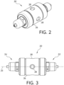
- Figures 2 through 4 are exterior views of an example combination pressure building regulator and final line regulator 30.
- the pressure building and final line regulators are combined into a single body, which reduces the number of devices connected to the cryogenic cylinder.
- the pressure building regulator 32 is located at one axial side of the combination regulator 30, and the final line regulator 34 is located at an opposite axial side of the combination regulator.
- the pressure building regulator 32 is axially aligned with the final line regulator 34 along an axis 35 of the regulator body 36.
- the regulators 32, 34 need not be axially aligned as shown.
- the body 36 of the combination regulator 30 includes a number of ports 38 arranged symmetrically around the circumference of the body 36 (e.g., spaced 90 degrees apart).
- the combination regulator 30 includes four ports 38 arranged symmetrically around the circumference of the regulator body 36 and located on the exterior surface of the regulator body and spaced along the exterior surface of the body.
- the ports are for connections to the input to the pressure building regulator (inlet port), the output of the final line regulator (outlet port), a gauge port, and a combined pressure building regulator outlet and final line regulator inlet port (combined inlet and outlet port).
- the inlet port for the pressure building regulator will be connected to and in fluid communication with the pressure building coil inside of the cylinder.
- the combined pressure building regulator outlet and final line regulator inlet port (combined inlet and outlet port) will be connected to and in fluid communication with the vapor space or head space within the cylinder.
- a pressure gauge can be connected to the gauge port to monitor the pressure of the final line regulator.
- the gauge port is in fluid communication with the output portion of the final line regulator.
- the final line regulator outlet port will be connected to the downstream process that utilizes the gas from the cylinder.
- a bulk storage system that includes the combination regulator 30 can further include additional shut off valves in-line with the ports as shown schematically in Fig. 1 , for example to isolate one or both of the regulators 32, 34.
- FIG. 5 and 6 Cross-sections of the combination pressure building regulator and final line regulator 30 are shown in Figs. 5 and 6 . It can be seen that the pressure building regulator 32 and the final line regulator 34 are similarly constructed. Each includes a spring 40a, 40b, a diaphragm 42a, 42b, and a valve assembly 44a, 44b attached to a respective diaphragm. The operations of the valve assemblies 44a, 44b are controlled by the corresponding regulator's pressure setpoint as established by the springs 40a, 40b and diaphragms 42a, 42b. The valve assemblies 44a, 44b are attached to and movable by their respective diaphragms 42a, 42b.
- the springs 40a, 40b are biasing members that apply a bias force against the diaphragms 42a, 42b, which tends to open the valves 44a, 44b when the regulated output pressures are less than the respective pressure setpoints.
- the respective pressure setpoints of the pressure building regulator 32 and the final line regulator 34 can be adjusted by screws 46a, 46b, which adjust the spring loads on the diaphragms 42a, 42b.
- Each regulator 32, 34 includes a bonnet 48a, 48b attached to the body 36.
- the bonnets 48a, 48b extend from opposite axial ends of the regulator body 36.
- the bias springs 40a, 40b are located within the bonnets 48a, 48b, and the bonnets cover the springs and diaphragms.
- the adjusting screws 46a, 46b extend through the bonnets 48a, 48b.
- the operation of diaphragm pressure regulators is known and need not be discussed in detail herein.
- the inlet port 50 of the combination regulator 30 can be seen in Fig. 5 .
- the inlet port 50 is in fluid communication with an input portion of the pressure building regulator 32 via an internal fluid channel 52 within the regulator body 36.
- the internal fluid channel 52 connects the input portion of the pressure building regulator 32 at the valve assembly 44a to the inlet port 50, which is connected to the pressure building coil on the cryogenic cylinder.
- the outlet port 54 of the combination regulator 30 can also be seen in Fig. 5 .
- the outlet port 54 is in fluid communication with an output portion of the final line regulator 34 via an internal fluid channel 56 within the regulator body 36.
- the internal fluid channel 56 connects the output portion of the final line regulator 34 at the downstream side of the valve assembly 44b to the outlet port 54, which is connected to a downstream processes that utilizes the stored gas.
- the gauge port 58 of the combination regulator 30 can be seen in Fig. 6 .
- the gauge port 58 is in fluid communication with the output portion of the final line regulator 34 via an internal fluid channel 60 within the regulator body 36.
- the internal fluid channel 60 connects the output portion of the final line regulator 34 at the downstream side of the valve assembly 44b to the gauge port 58.
- a pressure gauge can be connected to the gauge port 58 for monitoring the pressure of the gas supplied to the downstream process.
- the diameter of the internal fluid channel 60 that connects the output portion of the final line regulator 34 to the gauge port 58 can be the same as the internal fluid channel 56 that connects the output portion of the final line regulator to the outlet port 54, or the internal fluid channels 56, 60 can have different diameters. In the embodiment shown in the figures, the diameter of the internal fluid channel 60 that connects the output portion of the final line regulator 34 to the gauge port 58 is smaller than the diameter of the internal fluid channel 56 that connects the output portion of the final line regulator to the outlet port 54.
- the combined inlet and outlet port 62 of the combination regulator 30 can be seen in Fig. 6 .
- the combined inlet and outlet port 62 is in fluid communication with both of the output portion of the pressure building regulator 32 and the input portion of the final line regulator 34. It can be seen that the output portion of the pressure building regulator 32 is in fluid communication with the input portion of the final line regulator 34 within the regulator body 36.
- the regulator body 36 includes respective internal fluid channels 64, 66 that connect the combined inlet and outlet port 62 to the output portion of the of the pressure building regulator 32 (at the downstream side of the valve assembly 44a) and the input portion of the final line regulator 34 (at the upstream side of the valve assembly 44b).
- the pressure building regulator 32 regulates the pressure of the gas in the head space of the cylinder, and the final line regulator 34 receives gas from the head space/pressure building regulator 32 and regulates the supplied gas pressure to a downstream process.
- Fig. 6 shows separate internal fluid channels 64, 66 extending from the regulators 32, 34 to the combined inlet and outlet port 62
- the regulator body 36 could include an internal fluid channel that directly connects the output portion of the pressure building regulator 32 to the input portion of the final line regulator 34, so that the two regulators are in fluid communication with each other.
- the combination pressure building regulator and final line regulator 30 can be used on systems for delivering various cryogenic gasses.
- the combination regulator 30 is designed for use on CO2 cylinders used in the food and beverage industry for example.
- the combination regulator 30 can meet food and beverage use requirements promulgated by a standards-issuing organization, such as a government entity or other organization (e.g., NSF International). To that end, the combination regulator 30 does not expose the process gas that is discharged to a downstream process to any components that may contain lead.
- the pressure building regulator 32 will control and limit the head pressure of the CO2 cylinder.
- the valve 44a opens, liquid CO2 flows from the cylinder and through the cylinder's pressure building coil. Liquid and/or gas CO2 is pushed into the input side or input portion of the pressure building regulator 32 through its inlet port 50.
- the pressure regulating valve 44a and spring-loaded diaphragm 212a control the head pressure of the cylinder. Liquid and/or gas CO2 enters the pressure building regulator 32, is regulated to a specific pressure through the regulator, and the outlet of the pressure building regulator allows gaseous CO2 to enter the headspace or vapor space of the cylinder to maintain a constant head pressure.
- the pressure building regulator's pressure setting is increased (by compressing the spring 40a), the head pressure of the cylinder will be increased. Likewise, if the pressure building regulator's pressure setting is decreased (by reducing the spring's 40a compression), the head pressure of the cylinder will be decreased.
- An example pressure range for the pressure building regulator 32 is 120-130 PSI, although other pressure ranges are possible.
- the final line regulator 34 takes the output pressure from the pressure building regulator 32 and regulates this down to a usable level for a downstream process.
- An example pressure range for the output of the final line regulator 32 is 110-115 PSI, although other pressure ranges are possible.
- the output pressure of the pressure building regulator 32 is the input pressure to the final line regulator 34 (and also the head pressure of the cylinder).
- the outlet port 62 on the regulator body 36 for the pressure building regulator 32 is shared as the inlet port for the final line regulator 34.
- the regulator body 36 includes the combined inlet and outlet port 62.
- the output side or output portion of the pressure building regulator 32 is in fluid communication with the input side or input portion of the final line regulator 34, and in fluid communication with the combined inlet and outlet port 62, through the internal fluid channels 64, 66.
- the regulator body 36 can be made from aluminum barstock, anodized and cleaned for oxidizing gas service per CGA G-4.1.
- the combination regulator 30 can include 300 series stainless steel diaphragms for both the pressure building side and the final line regulator side.
- the valve seats and seal can be made from virgin PTFE which will be compatible with cryogenic temperatures. All internal wetted components can be either lead-free or electroless nickel plated with 100% coverage to insure the gas does not contact any leaded material.
- the various ports and internal passages can be sized so as not to restrict the required flow of gas out of the cylinder or the time to build the head pressure internally.
- the bonnets 48a, 48b can be constructed from zinc die cast, chrome plated.
- the springs 40a, 400b and pressure adjusting screws 46a, 46b do not come in contact with the gas and can be constructed of materials which perform the required function. Diaphragm seals can be made from VITON material.
- the ports on the regulator body can be 1/4 inch NPT (national pipe taper).
Landscapes
- Engineering & Computer Science (AREA)
- General Engineering & Computer Science (AREA)
- Mechanical Engineering (AREA)
- Physics & Mathematics (AREA)
- Fluid Mechanics (AREA)
- General Physics & Mathematics (AREA)
- Automation & Control Theory (AREA)
- Filling Or Discharging Of Gas Storage Vessels (AREA)
- Control Of Fluid Pressure (AREA)
- Safety Valves (AREA)
- Containers, Films, And Cooling For Superconductive Devices (AREA)
Claims (8)
- Kombinationsdruckregler (30), umfassend:- einen Reglerkörper (36), der einen Einlassanschluss (50) auf einer Außenoberfläche des Reglerkörpers (36) und einen Auslassanschluss (54) auf der Außenoberfläche des Reglerkörpers (36) aufweist,- einen ersten Druckregler (32); und- einen zweiten Druckregler (34);
wobei ein Eingangsabschnitt des ersten Druckreglers (32) in Fluidverbindung mit dem Einlassanschluss (50) steht und ein Ausgangsabschnitt des zweiten Druckreglers (34) in Fluidverbindung mit dem Auslassanschluss (54) steht; und gekennzeichnet durch:wobei der Reglerkörper (36) ferner einen kombinierten Einlass- und Auslassanschluss (62) auf der Außenoberfläche des Reglerkörpers (36) aufweist;wobei der erste Druckregler (32) eine erste Diaphragma (42a), eine erste Ventilanordnung (44a), die durch die erste Diaphragma (42a) bewegbar ist, und ein erstes Vorspannelement einschließt, das eine erste Vorspannkraft auf die erste Diaphragma (42a) aufbringt, um eine erste Druckreglereinstellung herzustellen;wobei der zweite Druckregler (34) eine zweite Diaphragma (42b), eine zweite Ventilanordnung (44b), die durch die zweite Diaphragma (42b) bewegbar ist, und ein zweites Vorspannelement einschließt, das eine zweite Vorspannkraft auf die zweite Diaphragma (42b) aufbringt, um eine zweite Druckreglereinstellung herzustellen, die sich von der ersten Druckreglereinstellung unterscheidet; undwobei sowohl ein Ausgangsabschnitt des ersten Druckreglers (32) als auch ein Eingangsabschnitt des zweiten Druckreglers (34) in Fluidverbindung mit dem kombinierten Einlass- und Auslassanschluss (62) stehen und/oder wobei der Ausgangsabschnitt des ersten Druckreglers (32) in Fluidverbindung mit dem Eingangsabschnitt des zweiten Druckreglers (34) innerhalb des Reglerkörpers (36) steht. - Kombinationsdruckregler (30) nach Anspruch 1, wobei der Reglerkörper (36) ferner einen Messanschluss einschließt, und wobei der Ausgangsabschnitt des zweiten Druckreglers (34) in Fluidverbindung mit dem Messanschluss steht,
wobei vorzugsweise der Einlassanschluss (50), der Auslassanschluss (54), der kombinierte Einlass- und Auslassanschluss (62) und der Messanschluss symmetrisch um den Reglerkörper (36) herum angeordnet sind. - Kombinationsdruckregler (30) nach Anspruch 2, wobei der Reglerkörper (36) einen inneren Fluidkanal, der den Ausgangsabschnitt des zweiten Druckreglers (34) mit dem Auslassanschluss (54) verbindet, und einen weiteren inneren Fluidkanal einschließt, der den Ausgangsabschnitt des zweiten Druckreglers (34) mit dem Messanschluss verbindet, und wobei ein Durchmesser des weiteren inneren Fluidkanals, der den Ausgangsabschnitt des zweiten Druckreglers (34) mit dem Messanschluss verbindet, kleiner als ein Durchmesser des inneren Fluidkanals ist, der den Ausgangsabschnitt des zweiten Druckreglers (34) mit dem Auslassanschluss (54) verbindet.
- Kombinationsdruckregler (30) nach einem der vorstehenden Ansprüche, ferner umfassend eine erste Haube, die sich von einem ersten Ende des Reglerkörpers (36) erstreckt, und eine zweite Haube, die sich von einem zweiten Ende des Reglerkörpers (36) gegenüber dem ersten Ende erstreckt, wobei sich das erste Vorspannelement innerhalb der ersten Haube befindet und sich das zweite Vorspannelement innerhalb der zweiten Haube befindet,
wobei vorzugsweise der erste Druckregler (32) an dem zweiten Druckregler (34) entlang einer Achse des Reglerkörpers (36) axial ausgerichtet ist. - Kombinationsdruckregler (30) nach einem der vorstehenden Ansprüche, wobei der Reglerkörper (36) einschließt:einen ersten inneren Fluidkanal, der den Eingangsabschnitt des ersten Druckreglers (32) mit dem Einlassanschluss (50) verbindet,einen zweiten inneren Fluidkanal, der den Ausgangsabschnitt des zweiten Druckreglers (34) mit dem Auslassanschluss (54) verbindet,einen dritten inneren Fluidkanal, der den Ausgangsabschnitt des ersten Druckreglers (32) mit dem kombinierten Einlass- und Auslassanschluss (62) verbindet, undeinen vierten inneren Fluidkanal, der den Eingangsabschnitt des zweiten Druckreglers (34) mit dem kombinierten Einlass- und Auslassanschluss (62) verbindet.
- Kombinationsdruckregler (30) nach Anspruch 2 und 5, wobei der Reglerkörper (36) ferner einen fünften inneren Fluidkanal einschließt, der den Ausgangsabschnitt des zweiten Druckreglers (34) mit dem Messanschluss verbindet.
- Kombinationsdruckregler (30) nach Anspruch 6, wobei der Einlassanschluss (50), der Auslassanschluss (54), der kombinierte Einlass- und Auslassanschluss (62) und der Messanschluss symmetrisch um den Reglerkörper (36) herum angeordnet sind.
- Kombinationsdruckregler (30) nach Anspruch 6 oder 7, wobei ein Durchmesser des fünften inneren Fluidkanals, der den Ausgangsabschnitt des zweiten Druckreglers (34) mit dem Messanschluss verbindet, kleiner als ein Durchmesser des zweiten inneren Fluidkanals ist, der den Ausgangsabschnitt des zweiten Druckreglers (34) mit dem Auslassanschluss (54) verbindet.
Applications Claiming Priority (2)
| Application Number | Priority Date | Filing Date | Title |
|---|---|---|---|
| US202163155848P | 2021-03-03 | 2021-03-03 | |
| US17/386,012 US11852255B2 (en) | 2021-03-03 | 2021-07-27 | Combination regulator for cryogenic tanks |
Publications (3)
| Publication Number | Publication Date |
|---|---|
| EP4063989A1 EP4063989A1 (de) | 2022-09-28 |
| EP4063989C0 EP4063989C0 (de) | 2024-03-27 |
| EP4063989B1 true EP4063989B1 (de) | 2024-03-27 |
Family
ID=80595465
Family Applications (1)
| Application Number | Title | Priority Date | Filing Date |
|---|---|---|---|
| EP22159204.1A Active EP4063989B1 (de) | 2021-03-03 | 2022-02-28 | Kombinationsregler für kryogene behälter |
Country Status (7)
| Country | Link |
|---|---|
| US (1) | US11852255B2 (de) |
| EP (1) | EP4063989B1 (de) |
| JP (1) | JP7841791B2 (de) |
| KR (1) | KR20220124649A (de) |
| CN (1) | CN115031161A (de) |
| AU (1) | AU2022201493A1 (de) |
| BR (1) | BR102022003858A2 (de) |
Families Citing this family (1)
| Publication number | Priority date | Publication date | Assignee | Title |
|---|---|---|---|---|
| USD1121536S1 (en) | 2023-06-12 | 2026-04-07 | Ghotra Innovations Inc. | Portable power station |
Family Cites Families (25)
| Publication number | Priority date | Publication date | Assignee | Title |
|---|---|---|---|---|
| US3495625A (en) | 1967-04-21 | 1970-02-17 | Mastabar Mining Equipment Co L | Rotary fluid flow control valve assembly |
| FR1562104A (de) | 1968-02-05 | 1969-04-04 | ||
| US3804056A (en) | 1972-09-15 | 1974-04-16 | Clow Corp | Valve indicator post |
| US3908871A (en) | 1974-10-15 | 1975-09-30 | Double Check Ind Inc | Keg closure and coupler assembly |
| US4624277A (en) * | 1985-10-03 | 1986-11-25 | Harry Veite | Pressure regulating and relief valve |
| JP2575057Y2 (ja) * | 1993-03-24 | 1998-06-25 | 株式会社ユタカ | 圧力調整器 |
| US5829472A (en) | 1997-08-04 | 1998-11-03 | Carten Controls Inc. | Dual contained purge connection for dual containment valves |
| DE29802433U1 (de) | 1998-02-16 | 1998-09-17 | GOK Regler- und Armaturen- Gesellschaft mbH & Co. KG, 97342 Seinsheim | Automatisches Zuschaltventil für Flüssiggas |
| JPH11282541A (ja) * | 1998-03-30 | 1999-10-15 | Koganei Corp | 調質機器用アダプタ |
| IT1302646B1 (it) | 1998-10-12 | 2000-09-29 | Pagani Algela | Regolatore di pressione a doppio stadio con doppia sicurezza,particolarmente per bombole di gas liquido. |
| US6742550B2 (en) | 1999-12-01 | 2004-06-01 | Rudolph Caparros | Secondary containment cap apparatus for either permanent or removable attachment to a primary chlorine container turret |
| FR2810260B1 (fr) | 2000-06-20 | 2002-08-30 | Air Liquide | Dispositif de stockage et de melange de deux gaz |
| ITMI20021879A1 (it) | 2002-09-03 | 2004-03-04 | Cavagna Group S P A Divisione Reca Ora Cavagna Gr | Dispositivo di regolazione del flusso di gas verso l'utilizzazione. |
| JP2005016709A (ja) | 2003-06-04 | 2005-01-20 | Neriki:Kk | ガス容器及びガス容器用バルブ装置並びにガス容器とバルブ装置の接続構造 |
| JP2005157913A (ja) | 2003-11-27 | 2005-06-16 | Yutaka:Kk | 圧力調整器 |
| JP2006107039A (ja) | 2004-10-04 | 2006-04-20 | Fuji Koki Kk | ガス圧力調整器 |
| DE102005012634B3 (de) | 2005-03-18 | 2006-05-11 | Honeywell B.V. | Gasregelgerät |
| JP2007046697A (ja) * | 2005-08-10 | 2007-02-22 | Fujikin Inc | 継手付き流体制御器 |
| JP2009041549A (ja) | 2007-08-13 | 2009-02-26 | Walbro Japan Inc | 液化ガスエンジン用燃料供給装置 |
| US8375983B2 (en) * | 2009-02-13 | 2013-02-19 | Tescom Corporation | Multi-stage fluid regulators |
| US20110061742A1 (en) * | 2009-09-11 | 2011-03-17 | Tyco Valves & Controls Lp | Cryogenic liquid cylinder manifold |
| GB201207833D0 (en) * | 2012-05-04 | 2012-06-20 | Norgren Ltd C A | Pressure regulator |
| PL2835709T3 (pl) * | 2013-08-06 | 2016-09-30 | Urządzenie do regulacji ciśnienia gazu | |
| EP2887169A1 (de) * | 2013-12-18 | 2015-06-24 | The Boeing Company | Leichter Gasdruckregler |
| WO2016057475A1 (en) * | 2014-10-06 | 2016-04-14 | Scott Technologies, Inc. | System and method for automatically filling fluid cylinders |
-
2021
- 2021-07-27 US US17/386,012 patent/US11852255B2/en active Active
-
2022
- 2022-02-28 EP EP22159204.1A patent/EP4063989B1/de active Active
- 2022-03-02 BR BR102022003858-9A patent/BR102022003858A2/pt not_active Application Discontinuation
- 2022-03-02 CN CN202210199668.8A patent/CN115031161A/zh active Pending
- 2022-03-02 KR KR1020220026987A patent/KR20220124649A/ko active Pending
- 2022-03-03 JP JP2022032623A patent/JP7841791B2/ja active Active
- 2022-03-03 AU AU2022201493A patent/AU2022201493A1/en not_active Abandoned
Also Published As
| Publication number | Publication date |
|---|---|
| JP2022136028A (ja) | 2022-09-15 |
| US11852255B2 (en) | 2023-12-26 |
| JP7841791B2 (ja) | 2026-04-07 |
| US20220282798A1 (en) | 2022-09-08 |
| KR20220124649A (ko) | 2022-09-14 |
| EP4063989C0 (de) | 2024-03-27 |
| EP4063989A1 (de) | 2022-09-28 |
| CN115031161A (zh) | 2022-09-09 |
| AU2022201493A1 (en) | 2022-09-22 |
| BR102022003858A2 (pt) | 2022-09-13 |
Similar Documents
| Publication | Publication Date | Title |
|---|---|---|
| KR100352886B1 (ko) | 개량된2단계압력조절기 | |
| US7134447B2 (en) | Gas pressure regulator | |
| US9977005B2 (en) | Gas sampling device and filling station comprising such a device | |
| EP4063989B1 (de) | Kombinationsregler für kryogene behälter | |
| US8281804B2 (en) | Pressure relief valves | |
| JP2004515841A (ja) | 圧力調整器 | |
| US11578810B2 (en) | Valve control assembly | |
| EP0781958A2 (de) | Vakuumisolierter Kryobehälter | |
| EP3467292B1 (de) | Integriertes erdgasdurchflussregulierungssystem mit kraftstofftemperaturhomogenisierung für verbesserte motorleistung und für verringerte emissionen | |
| US20180037307A1 (en) | Ultra-high pressure regulator and a method of using the same | |
| US20110061742A1 (en) | Cryogenic liquid cylinder manifold | |
| US3044486A (en) | Gas storage and delivery system | |
| US12535187B2 (en) | Double-skin cryogenic tank equipped with at least one inspection device | |
| US20060027272A1 (en) | Gas shut-off valve assembly | |
| KR20070038163A (ko) | 고압 탱크 및 밸브 어셈블리 | |
| US20150053290A1 (en) | Medical Gas Manifold | |
| US11906111B2 (en) | Delivery tank with pressure reduction, saturation and desaturation features | |
| US20160208934A1 (en) | Gas cylinder valve | |
| EP0779469B1 (de) | Einrichtung zum Versorgen eines Verbrauchers mit Kryokraftstoff aus einem Kryotank | |
| US11655908B2 (en) | Low pressure shut off valve and system | |
| DE102004057466B4 (de) | Druckregler für ein gasbetriebenes Kraftfahrzeug | |
| NO320602B1 (no) | Styreventil som styrer stromningen av gass i henhold til dens trykk | |
| DE3935171A1 (de) | Membranventil | |
| US20050229977A1 (en) | Flow regulating valve assembly | |
| JP2025539738A (ja) | コンパクトかつ壁面に取付可能なlngサンプル気化アセンブリ |
Legal Events
| Date | Code | Title | Description |
|---|---|---|---|
| PUAI | Public reference made under article 153(3) epc to a published international application that has entered the european phase |
Free format text: ORIGINAL CODE: 0009012 |
|
| STAA | Information on the status of an ep patent application or granted ep patent |
Free format text: STATUS: THE APPLICATION HAS BEEN PUBLISHED |
|
| AK | Designated contracting states |
Kind code of ref document: A1 Designated state(s): AL AT BE BG CH CY CZ DE DK EE ES FI FR GB GR HR HU IE IS IT LI LT LU LV MC MK MT NL NO PL PT RO RS SE SI SK SM TR |
|
| STAA | Information on the status of an ep patent application or granted ep patent |
Free format text: STATUS: REQUEST FOR EXAMINATION WAS MADE |
|
| 17P | Request for examination filed |
Effective date: 20230328 |
|
| RBV | Designated contracting states (corrected) |
Designated state(s): AL AT BE BG CH CY CZ DE DK EE ES FI FR GB GR HR HU IE IS IT LI LT LU LV MC MK MT NL NO PL PT RO RS SE SI SK SM TR |
|
| GRAP | Despatch of communication of intention to grant a patent |
Free format text: ORIGINAL CODE: EPIDOSNIGR1 |
|
| STAA | Information on the status of an ep patent application or granted ep patent |
Free format text: STATUS: GRANT OF PATENT IS INTENDED |
|
| INTG | Intention to grant announced |
Effective date: 20231113 |
|
| GRAS | Grant fee paid |
Free format text: ORIGINAL CODE: EPIDOSNIGR3 |
|
| GRAA | (expected) grant |
Free format text: ORIGINAL CODE: 0009210 |
|
| STAA | Information on the status of an ep patent application or granted ep patent |
Free format text: STATUS: THE PATENT HAS BEEN GRANTED |
|
| AK | Designated contracting states |
Kind code of ref document: B1 Designated state(s): AL AT BE BG CH CY CZ DE DK EE ES FI FR GB GR HR HU IE IS IT LI LT LU LV MC MK MT NL NO PL PT RO RS SE SI SK SM TR |
|
| REG | Reference to a national code |
Ref country code: GB Ref legal event code: FG4D |
|
| REG | Reference to a national code |
Ref country code: CH Ref legal event code: EP |
|
| REG | Reference to a national code |
Ref country code: DE Ref legal event code: R096 Ref document number: 602022002499 Country of ref document: DE |
|
| REG | Reference to a national code |
Ref country code: IE Ref legal event code: FG4D |
|
| U01 | Request for unitary effect filed |
Effective date: 20240418 |
|
| U07 | Unitary effect registered |
Designated state(s): AT BE BG DE DK EE FI FR IT LT LU LV MT NL PT SE SI Effective date: 20240425 |
|
| PG25 | Lapsed in a contracting state [announced via postgrant information from national office to epo] |
Ref country code: GR Free format text: LAPSE BECAUSE OF FAILURE TO SUBMIT A TRANSLATION OF THE DESCRIPTION OR TO PAY THE FEE WITHIN THE PRESCRIBED TIME-LIMIT Effective date: 20240628 |
|
| PG25 | Lapsed in a contracting state [announced via postgrant information from national office to epo] |
Ref country code: HR Free format text: LAPSE BECAUSE OF FAILURE TO SUBMIT A TRANSLATION OF THE DESCRIPTION OR TO PAY THE FEE WITHIN THE PRESCRIBED TIME-LIMIT Effective date: 20240327 Ref country code: RS Free format text: LAPSE BECAUSE OF FAILURE TO SUBMIT A TRANSLATION OF THE DESCRIPTION OR TO PAY THE FEE WITHIN THE PRESCRIBED TIME-LIMIT Effective date: 20240627 |
|
| PG25 | Lapsed in a contracting state [announced via postgrant information from national office to epo] |
Ref country code: RS Free format text: LAPSE BECAUSE OF FAILURE TO SUBMIT A TRANSLATION OF THE DESCRIPTION OR TO PAY THE FEE WITHIN THE PRESCRIBED TIME-LIMIT Effective date: 20240627 Ref country code: NO Free format text: LAPSE BECAUSE OF FAILURE TO SUBMIT A TRANSLATION OF THE DESCRIPTION OR TO PAY THE FEE WITHIN THE PRESCRIBED TIME-LIMIT Effective date: 20240627 Ref country code: HR Free format text: LAPSE BECAUSE OF FAILURE TO SUBMIT A TRANSLATION OF THE DESCRIPTION OR TO PAY THE FEE WITHIN THE PRESCRIBED TIME-LIMIT Effective date: 20240327 Ref country code: GR Free format text: LAPSE BECAUSE OF FAILURE TO SUBMIT A TRANSLATION OF THE DESCRIPTION OR TO PAY THE FEE WITHIN THE PRESCRIBED TIME-LIMIT Effective date: 20240628 |
|
| PG25 | Lapsed in a contracting state [announced via postgrant information from national office to epo] |
Ref country code: IS Free format text: LAPSE BECAUSE OF FAILURE TO SUBMIT A TRANSLATION OF THE DESCRIPTION OR TO PAY THE FEE WITHIN THE PRESCRIBED TIME-LIMIT Effective date: 20240727 |
|
| PG25 | Lapsed in a contracting state [announced via postgrant information from national office to epo] |
Ref country code: SM Free format text: LAPSE BECAUSE OF FAILURE TO SUBMIT A TRANSLATION OF THE DESCRIPTION OR TO PAY THE FEE WITHIN THE PRESCRIBED TIME-LIMIT Effective date: 20240327 |
|
| PG25 | Lapsed in a contracting state [announced via postgrant information from national office to epo] |
Ref country code: ES Free format text: LAPSE BECAUSE OF FAILURE TO SUBMIT A TRANSLATION OF THE DESCRIPTION OR TO PAY THE FEE WITHIN THE PRESCRIBED TIME-LIMIT Effective date: 20240327 |
|
| PG25 | Lapsed in a contracting state [announced via postgrant information from national office to epo] |
Ref country code: CZ Free format text: LAPSE BECAUSE OF FAILURE TO SUBMIT A TRANSLATION OF THE DESCRIPTION OR TO PAY THE FEE WITHIN THE PRESCRIBED TIME-LIMIT Effective date: 20240327 |
|
| PG25 | Lapsed in a contracting state [announced via postgrant information from national office to epo] |
Ref country code: PL Free format text: LAPSE BECAUSE OF FAILURE TO SUBMIT A TRANSLATION OF THE DESCRIPTION OR TO PAY THE FEE WITHIN THE PRESCRIBED TIME-LIMIT Effective date: 20240327 |
|
| PG25 | Lapsed in a contracting state [announced via postgrant information from national office to epo] |
Ref country code: SK Free format text: LAPSE BECAUSE OF FAILURE TO SUBMIT A TRANSLATION OF THE DESCRIPTION OR TO PAY THE FEE WITHIN THE PRESCRIBED TIME-LIMIT Effective date: 20240327 |
|
| PG25 | Lapsed in a contracting state [announced via postgrant information from national office to epo] |
Ref country code: SM Free format text: LAPSE BECAUSE OF FAILURE TO SUBMIT A TRANSLATION OF THE DESCRIPTION OR TO PAY THE FEE WITHIN THE PRESCRIBED TIME-LIMIT Effective date: 20240327 Ref country code: SK Free format text: LAPSE BECAUSE OF FAILURE TO SUBMIT A TRANSLATION OF THE DESCRIPTION OR TO PAY THE FEE WITHIN THE PRESCRIBED TIME-LIMIT Effective date: 20240327 Ref country code: RO Free format text: LAPSE BECAUSE OF FAILURE TO SUBMIT A TRANSLATION OF THE DESCRIPTION OR TO PAY THE FEE WITHIN THE PRESCRIBED TIME-LIMIT Effective date: 20240327 Ref country code: PL Free format text: LAPSE BECAUSE OF FAILURE TO SUBMIT A TRANSLATION OF THE DESCRIPTION OR TO PAY THE FEE WITHIN THE PRESCRIBED TIME-LIMIT Effective date: 20240327 Ref country code: IS Free format text: LAPSE BECAUSE OF FAILURE TO SUBMIT A TRANSLATION OF THE DESCRIPTION OR TO PAY THE FEE WITHIN THE PRESCRIBED TIME-LIMIT Effective date: 20240727 Ref country code: ES Free format text: LAPSE BECAUSE OF FAILURE TO SUBMIT A TRANSLATION OF THE DESCRIPTION OR TO PAY THE FEE WITHIN THE PRESCRIBED TIME-LIMIT Effective date: 20240327 Ref country code: CZ Free format text: LAPSE BECAUSE OF FAILURE TO SUBMIT A TRANSLATION OF THE DESCRIPTION OR TO PAY THE FEE WITHIN THE PRESCRIBED TIME-LIMIT Effective date: 20240327 |
|
| REG | Reference to a national code |
Ref country code: DE Ref legal event code: R097 Ref document number: 602022002499 Country of ref document: DE |
|
| PLBE | No opposition filed within time limit |
Free format text: ORIGINAL CODE: 0009261 |
|
| STAA | Information on the status of an ep patent application or granted ep patent |
Free format text: STATUS: NO OPPOSITION FILED WITHIN TIME LIMIT |
|
| 26N | No opposition filed |
Effective date: 20250103 |
|
| U20 | Renewal fee for the european patent with unitary effect paid |
Year of fee payment: 4 Effective date: 20250224 |
|
| U1H | Name or address of the proprietor changed after the registration of the unitary effect |
Owner name: LINCOLN GLOBAL, INC.; US |
|
| PG25 | Lapsed in a contracting state [announced via postgrant information from national office to epo] |
Ref country code: MC Free format text: LAPSE BECAUSE OF FAILURE TO SUBMIT A TRANSLATION OF THE DESCRIPTION OR TO PAY THE FEE WITHIN THE PRESCRIBED TIME-LIMIT Effective date: 20240327 |
|
| REG | Reference to a national code |
Ref country code: CH Ref legal event code: PL |
|
| PG25 | Lapsed in a contracting state [announced via postgrant information from national office to epo] |
Ref country code: CH Free format text: LAPSE BECAUSE OF NON-PAYMENT OF DUE FEES Effective date: 20250228 |
|
| PG25 | Lapsed in a contracting state [announced via postgrant information from national office to epo] |
Ref country code: IE Free format text: LAPSE BECAUSE OF NON-PAYMENT OF DUE FEES Effective date: 20250228 |