EP4063940B1 - Lichtteilende flache platte, lichtteilende vorrichtung, lichtteilende linse, kamera und elektronische vorrichtung - Google Patents
Lichtteilende flache platte, lichtteilende vorrichtung, lichtteilende linse, kamera und elektronische vorrichtung Download PDFInfo
- Publication number
- EP4063940B1 EP4063940B1 EP20913943.5A EP20913943A EP4063940B1 EP 4063940 B1 EP4063940 B1 EP 4063940B1 EP 20913943 A EP20913943 A EP 20913943A EP 4063940 B1 EP4063940 B1 EP 4063940B1
- Authority
- EP
- European Patent Office
- Prior art keywords
- beam splitter
- plate
- visible light
- infrared light
- transmissive plate
- Prior art date
- Legal status (The legal status is an assumption and is not a legal conclusion. Google has not performed a legal analysis and makes no representation as to the accuracy of the status listed.)
- Active
Links
Images


Classifications
-
- G—PHYSICS
- G02—OPTICS
- G02B—OPTICAL ELEMENTS, SYSTEMS OR APPARATUS
- G02B5/00—Optical elements other than lenses
- G02B5/20—Filters
- G02B5/208—Filters for use with infrared or ultraviolet radiation, e.g. for separating visible light from infrared and/or ultraviolet radiation
-
- G—PHYSICS
- G02—OPTICS
- G02B—OPTICAL ELEMENTS, SYSTEMS OR APPARATUS
- G02B27/00—Optical systems or apparatus not provided for by any of the groups G02B1/00 - G02B26/00, G02B30/00
- G02B27/10—Beam splitting or combining systems
- G02B27/1006—Beam splitting or combining systems for splitting or combining different wavelengths
-
- G—PHYSICS
- G02—OPTICS
- G02B—OPTICAL ELEMENTS, SYSTEMS OR APPARATUS
- G02B1/00—Optical elements characterised by the material of which they are made; Optical coatings for optical elements
- G02B1/10—Optical coatings produced by application to, or surface treatment of, optical elements
- G02B1/11—Anti-reflection coatings
-
- G—PHYSICS
- G02—OPTICS
- G02B—OPTICAL ELEMENTS, SYSTEMS OR APPARATUS
- G02B13/00—Optical objectives specially designed for the purposes specified below
- G02B13/14—Optical objectives specially designed for the purposes specified below for use with infrared or ultraviolet radiation
-
- G—PHYSICS
- G02—OPTICS
- G02B—OPTICAL ELEMENTS, SYSTEMS OR APPARATUS
- G02B27/00—Optical systems or apparatus not provided for by any of the groups G02B1/00 - G02B26/00, G02B30/00
- G02B27/10—Beam splitting or combining systems
- G02B27/14—Beam splitting or combining systems operating by reflection only
- G02B27/142—Coating structures, e.g. thin films multilayers
-
- G—PHYSICS
- G02—OPTICS
- G02B—OPTICAL ELEMENTS, SYSTEMS OR APPARATUS
- G02B27/00—Optical systems or apparatus not provided for by any of the groups G02B1/00 - G02B26/00, G02B30/00
- G02B27/18—Optical systems or apparatus not provided for by any of the groups G02B1/00 - G02B26/00, G02B30/00 for optical projection, e.g. combination of mirror and condenser and objective
-
- G—PHYSICS
- G02—OPTICS
- G02B—OPTICAL ELEMENTS, SYSTEMS OR APPARATUS
- G02B5/00—Optical elements other than lenses
- G02B5/20—Filters
- G02B5/28—Interference filters
- G02B5/281—Interference filters designed for the infrared light
- G02B5/282—Interference filters designed for the infrared light reflecting for infrared and transparent for visible light, e.g. heat reflectors, laser protection
-
- G—PHYSICS
- G02—OPTICS
- G02B—OPTICAL ELEMENTS, SYSTEMS OR APPARATUS
- G02B27/00—Optical systems or apparatus not provided for by any of the groups G02B1/00 - G02B26/00, G02B30/00
- G02B27/10—Beam splitting or combining systems
- G02B27/1006—Beam splitting or combining systems for splitting or combining different wavelengths
- G02B27/1013—Beam splitting or combining systems for splitting or combining different wavelengths for colour or multispectral image sensors, e.g. splitting an image into monochromatic image components on respective sensors
-
- H—ELECTRICITY
- H04—ELECTRIC COMMUNICATION TECHNIQUE
- H04N—PICTORIAL COMMUNICATION, e.g. TELEVISION
- H04N23/00—Cameras or camera modules comprising electronic image sensors; Control thereof
- H04N23/50—Constructional details
- H04N23/55—Optical parts specially adapted for electronic image sensors; Mounting thereof
Definitions
- This application relates to the field of electronic device technologies, and in particular, to a beam splitter plate, a beam splitter apparatus, a beam splitter lens module, a camera, and an electronic device.
- Low-illumination cameras are widely applied to military, security protection, public safety, and other fields because they can still capture clear images under low-illumination conditions.
- CN 203 414 717 U discloses a device for the frequency-division processing of short wave infrared and visible light of shooting/photographing equipment.
- CN 209 055 730 U discloses a camera module.
- the camera module comprises a lens and a shell.
- CN 104 856 653 A discloses a device and a method for detecting a blood vessel.
- the device comprises a visible light source, an optical fiber coupler, a lighting optical fiber, an imaging receiving channel, an infrared beam splitter, a far infrared lens zoom system, a far infrared detector, a visible light lens zoom system, a visible light image sensor and an image processing system.
- CN 109 445 116 A discloses a thermal image low-light fusion objective optical system.
- CN 101 510 007 A discloses a device for real time taking and self-adaptive fusion of infrared light images and visible light images.
- CN 102 736 153 A discloses an infrared cut-off filter with a low-angle effect.
- US 5 600 487 A discloses a dichroic mirror having a first portion including an H material layer having a high refractive index, and an M material layer having an intermediate refractive index, the H material layer and the M material layer being laminated repeatedly; and a second portion including an H material layer having a high refractive index, and an L material layer having a low refractive index, the H material layer and the L material layer being laminated repeatedly.
- US 5 193 025 A discloses an optical and infrared tracking system for use in a missile launcher to split the optical information received from a target into visible light portions and near infrared components.
- US 2010/193412 A1 discloses a device for splitting light between the visible light spectrum and the near infrared light spectrum, particularly for separating reflected light between the visible light spectrum and the near infrared light spectrum, in determining multiple characteristics of product in a product scanning system.
- Embodiments of this application provide a beam splitter apparatus, a beam splitter lens module, a camera, and an electronic device, to reduce a chromatic aberration and an off-axis aberration introduced by a beam splitter structure, and reduce difficulty in correcting a chromatic aberration and an off-axis aberration of a camera.
- 01 imaging lens module; 02: beam splitter structure; 021: first right angle prism; 0211: first right angle surface; 0212: second right angle surface; 0213: first inclined surface; 022: second right angle prism; 0221: third right angle surface; 0222: fourth right angle surface; 0223: second inclined surface; 023: beam splitter film; 03: visible light sensor; 04: near-infrared light sensor; 05: image fusion module; 1: beam splitter lens module; 11: imaging lens module; 111: lens barrel; 112: imaging lens group; 12: beam splitter apparatus; 121: housing; 122: connecting structure; 10: beam splitter plate; 101: transmissive plate; 1011: first surface; 1012: second surface; 101a: first transmissive plate; 1011a: first surface; 1012a: second surface; 101b: second transmissive plate; 1011b: first surface; 1012b: second surface; 102: beam splitter film; 103: first antireflective film; 104: second antireflective film;
- first and second in the embodiments of this application are merely intended for a purpose of description, and shall not be understood as an indication or implication of relative importance or implicit indication of a quantity of indicated technical features. Therefore, a feature limited by “first” or “second” may explicitly or implicitly include one or more features.
- FIG. 1 is a diagram of an imaging beam path of a camera according to some embodiments of this application.
- the camera is a low-illumination camera, and the camera can output a color image.
- an imaging lens module 01 focuses and forms an imaging beam a.
- the imaging beam a is incident into a beam splitter structure 02, and is split into visible light b and near-infrared light c by the beam splitter structure 02.
- the visible light b is incident into a visible light sensor 03, and the visible light sensor 03 converts the visible light b into a visible light signal.
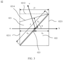
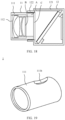
- FIG. 2 is a schematic diagram of a structure of the beam splitter structure 02 according to some embodiments of this application.
- the beam splitter structure 02 includes a beam splitter film 023, and a first right angle prism 021 and a second right angle prism 022 that are configured to support the beam splitter film 023.
- the first right angle prism 021 has a first right angle surface 0211, a second right angle surface 0212, and a first inclined surface 0213.
- the second right angle prism 022 has a third right angle surface 0221, a fourth right angle surface 0222, and a second inclined surface 0223.
- the first inclined surface 0213 and the second inclined surface 0223 are disposed in parallel and opposite to each other, and the beam splitter film 023 is sandwiched between the first inclined surface 0213 and the second inclined surface 0223.
- the imaging beam a focused by the imaging lens module is incident into the beam splitter structure 02 from the first right angle surface 0211 along a direction perpendicular to the first right angle surface 0211.
- the visible light b and the near-infrared light c in the imaging beam a are separated by the beam splitter film 023, the visible light b is emergent out of the beam splitter structure 02 from the third right angle surface 0221 along a direction perpendicular to the third right angle surface 0221, and the near-infrared light c is emergent out of the beam splitter structure 02 from the second right angle surface 0212.
- the separated near-infrared light c is emergent out of the beam splitter structure 02 from the second right angle surface 0212 along a direction perpendicular to the second right angle surface 0212.
- a transmission path length l 02 of the separated near-infrared light c in the first right angle prism 021 is equal to a transmission path length l 01 of the separated visible light b in the second right angle prism 022.
- the separated near-infrared light c can be emergent out of the beam splitter structure 02 from a surface 0214 formed after the cutting and along a direction perpendicular to the surface 0214, and a transmission path length l 02 of the separated near-infrared light c in the first right angle prism 021 is equal to a transmission path length l 01 of the separated visible light b in the second right angle prism 022.
- a region that is on the first right angle prism 021 and that is adjacent to the second right angle surface 0212 is supplemented with a part of a prism, and the supplementary part is a part enclosed by a dashed line shown in FIG. 4 .
- the separated near-infrared light c can be emergent out of the beam splitter structure 02 from a surface 0215 formed after the supplementation and along a direction perpendicular to the surface 0215, and a transmission path length l 02 of the separated near-infrared light c in the first right angle prism 021 is equal to a transmission path length l 01 of the separated visible light b in the second right angle prism 022.
- l 03 is a transmission path length of the imaging beam a in the first right angle prism 021 before the imaging beam a is incident into the beam splitter film 023.
- D is a thickness of the beam splitter structure 02 along the optical axis direction of the imaging beam. To ensure that the first right angle prism 021 and the second right angle prism 022 can be obtained by processing, a dimension of D is usually in centimeters.
- L is a width of the beam splitter film 023 in an inclination direction of itself.
- L ⁇ cos ⁇ represents the projection length of the beam splitter film 023 on the optical axis of the imaging beam a.
- a material of the first right angle prism 021 is the same as a material of the second right angle prism 022, and n 0 is a refractive index of the material of the first right angle prism 021 or the second right angle prism 022.
- the visible light and the near-infrared light in the imaging beam a have relatively long optical paths when transmitted in the beam splitter structure 02, which causes a relatively large chromatic aberration and off-axis aberration, and make it relatively difficult to correct a chromatic aberration and an off-axis aberration of the camera.
- the electronic device includes but is not limited to a mobile phone terminal, an in-vehicle terminal, and a smart wearable device, the electronic device includes a camera, and the camera is a low-illumination camera that can output a color image.
- FIG. 5 is a schematic diagram of a structure of a camera according to some embodiments of this application.
- the camera includes a beam splitter lens module 1.
- the beam splitter lens module 1 is configured to focus to form an imaging beam, and split the imaging beam into visible light and near-infrared light.
- FIG. 6 is a schematic diagram of a structure of the beam splitter lens module 1 according to some embodiments of this application.
- the beam splitter lens module 1 includes an imaging lens module 11 and a beam splitter apparatus 12.
- the imaging lens module 11 is configured to focus to form an imaging beam.
- the imaging lens module 11 may be a common C/CS lens module with a relatively long back focal length, or may be a fixed-focus or zoom lens module. This is not specifically limited herein.
- the beam splitter apparatus 12 is configured to split the imaging beam formed by focusing by the imaging lens module 11 into visible light and near-infrared light.
- FIG. 7 is a cutaway drawing of the imaging lens module of the beam splitter lens module shown in FIG. 6 .
- the imaging lens module 11 includes a lens barrel 111 and an imaging lens group 112 disposed in the lens barrel 111.
- the lens barrel 111 is configured to fix the imaging lens group 112.
- a material of the lens barrel 111 includes but is not limited to metal and plastic.
- the lens barrel 111 has an image side end A, and the image side end A is an end that is of the lens barrel 111 and that is close to an image side.
- the imaging lens group 112 includes at least one lens, the imaging lens group 112 is configured to focus to form an imaging beam, the imaging lens group 112 has an image side surface B, and the image side surface B is a surface that is of the imaging lens group 112 and that faces the image side.
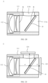
- FIG. 8 is a cutaway drawing of the beam splitter apparatus of the beam splitter lens module shown in FIG. 6 .
- the beam splitter apparatus 12 includes a housing 121, a connecting structure 122, and a beam splitter plate 10.
- a material of the housing 121 includes but is not limited to metal and plastic, and the housing 121 is provided with a light inlet C.
- the connecting structure 122 is disposed on a housing edge at the light inlet C, and the connecting structure 122 includes but is not limited to a screw thread and a buckle.
- the beam splitter plate 10 is disposed obliquely in the housing 121, and the beam splitter plate 10 can separate visible light from near-infrared light in an imaging beam incident from the light inlet C.
- the beam splitter plate 10 includes a transmissive plate and a beam splitter film.
- the transmissive plate is a light-transmitting plate-like structure.
- the beam splitter film is supported on the transmissive plate and is parallel to the transmissive plate.
- the beam splitter film is configured to reflect visible light and transmit near-infrared light, or the beam splitter film is configured to reflect near-infrared light and transmit visible light.
- a thickness d of the transmissive plate satisfies that when the beam splitter plate is disposed obliquely in a transmission path of the imaging beam of the camera, transmission path lengths of visible light and near-infrared light in the imaging beam in the transmissive plate are both less than a projection length of the beam splitter film on an optical axis of the imaging beam.
- the beam splitter film is configured to reflect visible light and transmit near-infrared light, or the beam splitter film is configured to reflect near-infrared light and transmit visible light, visible light and near-infrared light in an imaging beam path can be separated by using the beam splitter film.
- the beam splitter film is supported on the transmissive plate and is parallel to the transmissive plate, and the thickness d of the transmissive plate satisfies that when the beam splitter plate is disposed obliquely in the transmission path of the imaging beam of the camera, the transmission path lengths of the visible light and the near-infrared light in the imaging beam in the transmissive plate are both less than the projection length of the beam splitter film on the optical axis of the imaging beam.
- the projection length of the beam splitter film on the optical axis of the imaging beam a is L ⁇ cos ⁇ .
- a material used for the beam splitter plate is the same as the material of the first right angle prism 021 or the second right angle prism 022 in the embodiment shown in FIG. 2 , FIG. 3 , or FIG.
- the visible light and the near-infrared light in the imaging beam have relatively short optical paths when transmitted in the transmissive plate, which causes a relatively small chromatic aberration and off-axis aberration, and helps reduce difficulty in correcting a chromatic aberration and an off-axis aberration of the camera.
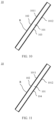
- FIG. 9 is a schematic diagram of a structure of a beam splitter plate 10 which is not an embodiment of this application.
- the beam splitter plate 10 includes a transmissive plate 101 and a beam splitter film 102.
- a material of the transmissive plate 101 includes but is not limited to optical glass.
- the transmissive plate 101 has a first surface 1011 and a second surface 1012 opposite to each other, and the first surface 1011 and the second surface 1012 are perpendicular to a thickness direction of the transmissive plate 101.
- the beam splitter film 102 is disposed on the first surface 1011.
- the structure is simple and is easy to implement.
- the imaging beam a is incident from a surface that is on the beam splitter film 102 and that is in a direction away from the transmissive plate 101 (that is, a light receiving surface R of the beam splitter plate 10), as shown in FIG. 9 , the imaging beam a is incident into the beam splitter plate 10 from the light receiving surface R.
- the beam splitter film 102 reflects one (for example, near-infrared light c ) of the near-infrared light and the visible light in the imaging beam, and transmits the other (for example, visible light b ) of the near-infrared light and the visible light.
- n sin ⁇ /sin ⁇ .
- L 1 d ⁇ n /sin ⁇ can be deduced from that.
- n is a refractive index of the material of the transmissive plate 101.
- the thickness d of the transmissive plate 101 satisfies that the transmission path lengths of the visible light and the near-infrared light in the imaging beam a are both less than the projection length of the beam splitter film 102 on the optical axis of the imaging beam a, that is, the thickness d of the transmissive plate 101 satisfies d ⁇ L sin ⁇ cos ⁇ / n .
- the beam splitter plate 10 When the beam splitter film 102 is configured to reflect near-infrared light and transmit visible light, to increase a transmittance of the visible light at the second surface 1012 of the transmissive plate 101, in some examples, as shown in FIG. 10 , the beam splitter plate 10 further includes a first antireflective film 103.
- the first antireflective film 103 is attached to the second surface 1012.
- the first antireflective film 103 is configured to increase a transmittance of visible light emergent out of the transmissive plate 101 from the second surface 1012, and the transmitted visible light passes through the first antireflective film 103.
- the beam splitter plate 10 When the beam splitter film 102 is configured to reflect visible light and transmit near-infrared light, to increase a transmittance of the near-infrared light at the second surface 1012 of the transmissive plate 101, in some examples, as shown in FIG. 11 , the beam splitter plate 10 further includes a second antireflective film 104.
- the second antireflective film 104 is attached to the second surface 1012.
- the second antireflective film 104 is configured to increase a transmittance of near-infrared light emergent out of the transmissive plate 101 from the second surface 1012, and the transmitted near-infrared light passes through the second antireflective film 104.
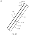
- FIG. 12 is a schematic diagram of a structure of a beam splitter plate 10 according to some other examples of this application.
- the beam splitter plate 10 includes a transmissive plate 101 and a beam splitter film 102.
- a material of the transmissive plate 101 includes but is not limited to optical glass.
- the transmissive plate 101 has a first surface 1011 and a second surface 1012 opposite to each other, and the first surface 1011 and the second surface 1012 are perpendicular to a thickness direction of the transmissive plate 101.
- the beam splitter film 102 is attached to the second surface 1012.
- the structure is simple and is easy to implement.
- the imaging beam a is incident from the first surface 1011 (that is, a light receiving surface R of the beam splitter plate 10), as shown in FIG. 12 , the imaging beam a is incident into the beam splitter plate 10 from the light receiving surface R.
- the beam splitter film 102 reflects one (for example, near-infrared light c ) of the near-infrared light and the visible light in the imaging beam, and transmits the other (for example, visible light b ) of the near-infrared light and the visible light.
- n sin ⁇ /sin ⁇ .
- L 1 d ⁇ n /sin ⁇ and 2 ⁇ d ⁇ n /sin ⁇ can be deduced from that.
- the thickness d of the transmissive plate 101 satisfies that the transmission path lengths of the visible light and the near-infrared light in the imaging beam a are both less than the projection length of the beam splitter film 102 on the optical axis of the imaging beam a, that is, the thickness d of the transmissive plate 101 satisfies d ⁇ L sin ⁇ cos ⁇ / 2n.
- the beam splitter plate 10 further includes a third antireflective film 105.
- the third antireflective film 105 is attached to the first surface 1011.
- the third antireflective film 105 is configured to increase transmittances of visible light and near-infrared light that are incident into the transmissive plate 101 from the first surface 1011, and the visible light and the near-infrared light in the imaging beam pass through the third antireflective film 105.
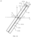
- FIG. 14 is a schematic diagram of a structure of a beam splitter plate 10 according to some other embodiments of this application.
- the beam splitter plate 10 includes a first transmissive plate 101a, a second transmissive plate 101b, and a beam splitter film 102.
- Materials of the first transmissive plate 101a and the second transmissive plate 101b include but are not limited to optical glass.
- the first transmissive plate 101a has a first surface 1011a and a second surface 1012a opposite to each other, and the first surface 1011a and the second surface 1012a are perpendicular to a thickness direction of the first transmissive plate 101a.
- the second transmissive plate 101b has a first surface 1011b and a second surface 1012b opposite to each other, and the first surface 1011b and the second surface 1012b are perpendicular to a thickness direction of the second transmissive plate 101b.
- the beam splitter film 102 is sandwiched between the second surface 1012a and the first surface 1011b.
- the beam splitter film 102 is configured to reflect visible light and transmit near-infrared light, or the beam splitter film 102 is configured to reflect near-infrared light and transmit visible light.
- the structure is simple and easy to implement, and can perform waterproof and dustproof protection on the beam splitter film.
- the imaging beam a is incident from the first surface 1011a (that is, a light receiving surface R of the beam splitter plate 10), as shown in FIG. 14 , the imaging beam a is incident into the beam splitter plate 10 from the light receiving surface R.
- the beam splitter film 102 reflects one (for example, near-infrared light c ) of the near-infrared light and the visible light in the imaging beam, and transmits the other (for example, visible light b ) of the near-infrared light and the visible light.
- n sin ⁇ /sin ⁇ .
- n is a refractive index of the material of the transmissive plate 101.
- d 1 is a thickness of the first transmissive plate 101a.
- d 2 is a thickness of the second transmissive plate 101b.
- the thickness d of the transmissive plate 101 satisfies that the transmission path lengths of the visible light and the near-infrared light in the imaging beam a are both less than the projection length of the beam splitter film 102 on the optical axis of the imaging beam a, that is, the thickness d of the transmissive plate 101 satisfies d ⁇ L sin ⁇ cos ⁇ / n and d 1 ⁇ d 2 .
- the beam splitter plate 10 further includes a fourth antireflective film 106.
- the fourth antireflective film 106 is attached to the first surface 1011a of the first transmissive plate 101a.
- the fourth antireflective film 106 is configured to increase transmittances of visible light and near-infrared light that are incident into the first transmissive plate 101a from the first surface 1011a of the first transmissive plate 101a, and the visible light and the near-infrared light in the imaging beam pass through the fourth antireflective film 106.
- the beam splitter plate 10 further includes a fifth antireflective film 107.
- the fifth antireflective film 107 is attached to the second surface 1012b of the second transmissive plate 101b.
- the fifth antireflective film 107 is configured to increase a transmittance of visible light emergent out of the second transmissive plate 101b from the second surface 1012b of the second transmissive plate 101b, and the transmitted visible light passes through the fifth antireflective film 107.
- the beam splitter plate 10 When the beam splitter film 102 is configured to reflect visible light and transmit near-infrared light, to increase a transmittance of the near-infrared light at the second surface 1012b of the second transmissive plate 101b, in some embodiments, as shown in FIG. 17 , the beam splitter plate 10 further includes a sixth antireflective film 108.
- the sixth antireflective film 108 is attached to the second surface 1012b of the second transmissive plate 101b.
- the sixth antireflective film 108 is configured to increase a transmittance of near-infrared light emergent out of the second transmissive plate 101b from the second surface 1012b of the second transmissive plate 101b, and the transmitted near-infrared light passes through the sixth antireflective film 108.
- the thickness d of the transmissive plate 101 is less than 0.5 mm. In this way, the thickness of the transmissive plate 101 is relatively small, and when the beam splitter plate 10 is disposed obliquely in the transmission path of the imaging beam of the camera, the transmission path lengths of the visible light b and the near-infrared light c in the imaging beam a in the transmissive plate 101 are relatively small, which causes a relatively small chromatic aberration and off-axis aberration, and reduces difficulty in correcting a chromatic aberration and an off-axis aberration of the camera.
- the inclination angle ⁇ of the beam splitter plate 10 is 40° to 60°. When the inclination angle of the beam splitter plate 10 is within this range, visible light and near-infrared light can be separated.
- the beam splitter apparatus 12 further includes a visible light sensor 123 and a near-infrared light sensor 124.
- the visible light sensor 123 is disposed in the housing 121, and the visible light sensor 123 is configured to convert the visible light b reflected or transmitted by the beam splitter plate 10 into a visible light signal.
- the near-infrared light sensor 124 is disposed in the housing 121, and the near-infrared light sensor 124 is configured to convert the near-infrared light c transmitted or reflected by the beam splitter plate 10 into a luminance signal.
- the beam splitter plate 10, the visible light sensor 123, and the near-infrared light sensor 124 are integrated in the same housing, so that accuracy of optical paths from the beam splitter plate 10 to the visible light sensor 123 and from the beam splitter plate 10 to the near-infrared light sensor 124 can be ensured.
- the beam splitter apparatus 12 further includes a visible light filter (not shown in the figure), the visible light filter is disposed between the beam splitter plate 10 and the near-infrared light sensor 124, and the visible light filter is configured to filter out visible light in the near-infrared light reflected or transmitted by the beam splitter plate 10. In this way, the visible light and the near-infrared light can be further separated, to avoid interference from the visible light to sensing and collection of the near-infrared light.
- a visible light filter not shown in the figure
- the visible light filter is disposed between the beam splitter plate 10 and the near-infrared light sensor 124, and the visible light filter is configured to filter out visible light in the near-infrared light reflected or transmitted by the beam splitter plate 10. In this way, the visible light and the near-infrared light can be further separated, to avoid interference from the visible light to sensing and collection of the near-infrared light.
- the beam splitter apparatus 12 further includes a near-infrared light filter (not shown in the figure), the near-infrared light filter is disposed between the beam splitter plate 10 and the visible light sensor 123, and the near-infrared light filter is configured to filter out near-infrared light in the visible light reflected or transmitted by the beam splitter plate 10. In this way, the near-infrared light and the visible light can be further separated, to avoid interference from the near-infrared light to sensing and collection of the visible light.
- a near-infrared light filter not shown in the figure
- the near-infrared light filter is disposed between the beam splitter plate 10 and the visible light sensor 123
- the near-infrared light filter is configured to filter out near-infrared light in the visible light reflected or transmitted by the beam splitter plate 10. In this way, the near-infrared light and the visible light can be further separated, to avoid interference from the near-infrared light to sensing and collection of
- FIG. 18 is a cutaway drawing of the beam splitter lens module shown in FIG. 6 .
- the housing 121 of the beam splitter apparatus 12 is connected to the image side end A of the lens barrel 111 of the imaging lens module 11 by using the connecting structure 122, and the light inlet C of the beam splitter apparatus 12 is opposite to the image side surface B of the imaging lens group 112 of the imaging lens module 11.
- the beam splitter lens module is assembled, and the beam splitter apparatus can be assembled with different imaging lens modules to form beam splitter lens modules having different functions, which makes it unnecessary to develop a new beam splitter lens module, thereby saving development costs of the beam splitter lens module.
- FIG. 19 is a schematic diagram of a structure of a beam splitter lens module 1 according to some other embodiments of this application.
- FIG. 20 is a cutaway drawing of the beam splitter lens module shown in FIG. 19 .
- the beam splitter lens module 1 includes a lens barrel 111, an imaging lens group 112, and a beam splitter plate 10.
- the lens barrel 111 is configured to fix the imaging lens group 112 and the beam splitter plate 10.
- a material of the lens barrel 111 includes but is not limited to metal and plastic.
- the imaging lens group 112 is disposed in the lens barrel 111, the imaging lens group 112 includes at least one lens, and the imaging lens group 112 is configured to focus to form an imaging beam.
- the beam splitter plate 10 is the same as the beam splitter plate 10 in the beam splitter apparatus 12, the beam splitter plate 10 is disposed obliquely in the lens barrel 111, the beam splitter plate 10 is located on an image side of the imaging lens group 112, and a light receiving surface R of the beam splitter plate 10 faces an image side surface B of the imaging lens group.
- the imaging lens group 112 and the beam splitter plate 10 are integrated into the lens barrel 111, so that relative position accuracy between the imaging lens group 112 and the beam splitter plate 10 can be ensured, and accuracy of an optical path from the imaging lens group 112 to the beam splitter plate 10 can be ensured.
- a first opening 111a is enclosed by an image side end of the lens barrel 111, and visible light or near-infrared light transmitted by the beam splitter plate 10 can be emergent from the first opening 111a.
- a second opening 111b is provided on a side wall of the lens barrel 111, and near-infrared light or visible light reflected by the beam splitter plate 10 can be emergent from the second opening 111b.
- the beam splitter lens module 1 further includes a visible light sensor 123 and a near-infrared light sensor 124.
- the visible light sensor 123 is disposed outside the lens barrel 111 and fixed to the lens barrel 111, and the visible light sensor 123 is configured to convert the visible light b reflected or transmitted by the beam splitter plate 10 into a visible light signal.
- the near-infrared light sensor 124 is disposed outside the lens barrel 111 and fixed to the lens barrel 111, and the near-infrared light sensor 124 is configured to convert the near-infrared light c transmitted or reflected by the beam splitter plate 10 into a luminance signal.
- the beam splitter plate 10, the visible light sensor 123, and the near-infrared light sensor 124 are fixed together, so that accuracy of optical paths from the beam splitter plate 10 to the visible light sensor 123 and from the beam splitter plate 10 to the near-infrared light sensor 124 can be ensured.
- the beam splitter lens module 1 further includes a visible light filter (not shown in the figure), the visible light filter is disposed between the beam splitter plate 10 and the near-infrared light sensor 124, and the visible light filter is configured to filter out visible light in the near-infrared light reflected or transmitted by the beam splitter plate 10. In this way, the visible light and the near-infrared light can be further separated, to avoid interference from the visible light to sensing and collection of the near-infrared light.
- a visible light filter not shown in the figure
- the visible light filter is disposed between the beam splitter plate 10 and the near-infrared light sensor 124
- the visible light filter is configured to filter out visible light in the near-infrared light reflected or transmitted by the beam splitter plate 10. In this way, the visible light and the near-infrared light can be further separated, to avoid interference from the visible light to sensing and collection of the near-infrared light.
- the beam splitter lens module 1 further includes a near-infrared light filter (not shown in the figure), the near-infrared light filter is disposed between the beam splitter plate 10 and the visible light sensor 123, and the near-infrared light filter is configured to filter out near-infrared light in the visible light reflected or transmitted by the beam splitter plate 10. In this way, the near-infrared light and the visible light can be further separated, to avoid interference from the near-infrared light to sensing and collection of the visible light.
- a near-infrared light filter is disposed between the beam splitter plate 10 and the visible light sensor 123
- the near-infrared light filter is configured to filter out near-infrared light in the visible light reflected or transmitted by the beam splitter plate 10. In this way, the near-infrared light and the visible light can be further separated, to avoid interference from the near-infrared light to sensing and collection of the visible light.
- the camera further includes a camera host 2, and the camera host 2 includes an image fusion module (not shown in the figure).
- the image fusion module is electrically connected to the visible light sensor 123, and the image fusion module is electrically connected to the near-infrared light sensor 124.
- the image fusion module is configured to perform separate image processing on the visible light signal converted by the visible light sensor 123 and the luminance signal converted by the near-infrared light sensor 124, and fuse a processed visible light signal and a processed luminance signal.
Landscapes
- Physics & Mathematics (AREA)
- General Physics & Mathematics (AREA)
- Optics & Photonics (AREA)
- Health & Medical Sciences (AREA)
- Toxicology (AREA)
- Blocking Light For Cameras (AREA)
- Studio Devices (AREA)
- Optical Elements Other Than Lenses (AREA)
Claims (10)
- Strahlteilereinrichtung (12), die umfasst:ein Gehäuse (121), das mit einem Lichteinlass (C) versehen ist;eine Verbindungsstruktur (122), die an einer Gehäusekante an dem Lichteinlass (C) angeordnet ist, wobei die Verbindungsstruktur (122) konfiguriert ist, um mit einem bildseitigen Ende eines Linsentubus (111) eines Abbildungslinsenmoduls (11) verbunden zu werden, sodass der Lichteinlass (C) einer bildseitigen Oberfläche (B) einer Abbildungslinsengruppe (112) des Abbildungslinsenmoduls (11) gegenüberliegt; undeine Strahlteilerplatte (10), die schräg in dem Gehäuse (121) und in einem Durchlasspfad eines Abbildungsstrahls einer Kamera angeordnet ist, die umfasst:eine durchlässige Platte (101), die eine lichtdurchlässige plattenartige Struktur ist; undeine Strahlteilerfolie (102), die auf der durchlässigen Platte (101) getragen wird und parallel zu der durchlässigen Platte (101) ist, wobei die Strahlteilerfolie (102) konfiguriert ist, um sichtbares Licht zu reflektieren und Nahinfrarotlicht durchzulassen, oder die Strahlteilerfolie (102) konfiguriert ist, um Nahinfrarotlicht zu reflektieren und sichtbares Licht durchzulassen, wobeieine Dicke der durchlässigen Platte (101) genügt, dass, wenn die Strahlteilerplatte (101) schräg in dem Durchlasspfad des Abbildungsstrahls der Kamera angeordnet ist, Durchlasspfadlängen von sichtbarem Licht und Nahinfrarotlicht in dem Abbildungsstrahl in der durchlässigen Platte beide kürzer als eine Projektionslänge der Strahlteilerfolie auf einer optischen Achse des Abbildungsstrahls sind,wobei die durchlässige Platte (101) eine erste Oberfläche (1011) und eine zweite Oberfläche (1012), die einander gegenüberliegen, aufweist; unddie Strahlteilerfolie (102) an der zweiten Oberfläche (1012) angebracht ist und wobei die Strahlteilerplatte (101) ferner umfasst:
eine dritte Antireflexfolie (105), die an der ersten Oberfläche (1011) angebracht ist, wobei die dritte Antireflexfolie (105) konfiguriert ist, um Durchlässigkeiten von sichtbarem Licht und Nahinfrarotlicht, die von der ersten Oberfläche (1011) in die durchlässige Platte (101) einfallen, zu erhöhen. - Strahlteilereinrichtung nach Anspruch 1, wobei die durchlässige Platte eine erste durchlässige Platte (101a) und eine zweite durchlässige Platte (101b) umfasst;die erste durchlässige Platte (101a) eine erste Oberfläche (1011a) und eine zweite Oberfläche (1012a), die einander gegenüberliegen, aufweist;die zweite durchlässige Platte (101b) eine erste Oberfläche (1011b) und eine zweite Oberfläche (1012b), die einander gegenüberliegen, aufweist; unddie Strahlteilerfolie zwischen der zweiten Oberfläche (1012a) der ersten durchlässigen Platte (101a) und der ersten Oberfläche (1011b) der zweiten durchlässigen Platte (101b) eingeschoben ist.
- Strahlteilereinrichtung nach Anspruch 2, wobei die Strahlteilerplatte ferner umfasst: eine vierte Antireflexfolie (106), die an der ersten Oberfläche der ersten durchlässigen Platte angebracht ist, wobei die vierte Antireflexfolie (106) konfiguriert ist, um Durchlässigkeiten von sichtbarem Licht und Nahinfrarotlicht, die von der ersten Oberfläche der ersten durchlässigen Platte in die erste durchlässige Platte einfallen, zu erhöhen.
- Strahlteilereinrichtung nach Anspruch 2 oder 3, wobei, wenn die Strahlteilerfolie Nahinfrarotlicht reflektiert und sichtbares Licht durchlässt, die Strahlteilerplatte ferner umfasst:eine fünfte Antireflexfolie (107), die an der zweiten Oberfläche der zweiten durchlässigen Platte angebracht ist, wobei die fünfte Antireflexfolie (107) konfiguriert ist, um eine Durchlässigkeit von sichtbarem Licht, das aus der zweiten durchlässigen Platte von der zweiten Oberfläche der zweiten durchlässigen Platte austritt, zu erhöhen; undwenn die Strahlteilerfolie sichtbares Licht reflektiert und Nahinfrarotlicht durchlässt, die Strahlteilerplatte ferner umfasst:
eine sechste Antireflexfolie (108), die an der zweiten Oberfläche der zweiten durchlässigen Platte angebracht ist, wobei die sechste Antireflexfolie (108) konfiguriert ist, um eine Durchlässigkeit von Nahinfrarotlicht, das aus der zweiten durchlässigen Platte von der zweiten Oberfläche der zweiten durchlässigen Platte austritt, zu erhöhen. - Strahlteilereinrichtung nach Anspruch 1, die ferner umfasst:einen Sensor (123) für sichtbares Licht, der in dem Gehäuse angeordnet ist, wobei der Sensor (123) für sichtbares Licht konfiguriert ist, um sichtbares Licht, das durch die Strahlteilerplatte reflektiert oder durchgelassen wird, in ein sichtbares Lichtsignal umzuwandeln; undeinen Nahinfrarotlichtsensor (124), der in dem Gehäuse angeordnet ist, wobei der Nahinfrarotlichtsensor (124) konfiguriert ist, um Nahinfrarotlicht, das durch die Strahlteilerplatte durchgelassen oder reflektiert wird, in ein Luminanzsignal umzuwandeln.
- Strahlteilerlinsenmodul (1), das umfasst:ein Abbildungslinsenmodul (11), das einen Linsentubus (111) und eine Abbildungslinsengruppe (112), die in dem Linsentubus (111) angeordnet ist, umfasst, wobei der Linsentubus (111) ein bildseitiges Ende aufweist, die Abbildungslinsengruppe (112) konfiguriert ist, um zu fokussieren, um einen Abbildungsstrahl auszubilden, und die Abbildungslinsengruppe (112) eine bildseitige Oberfläche aufweist; undeine Strahlteilereinrichtung (12), die die Strahlteilereinrichtung nach einem der Ansprüche 1 bis 5 ist, wobei ein Gehäuse (121) der Strahlteilereinrichtung (12) durch Verwenden einer Verbindungsstruktur mit dem bildseitigen Ende des Linsentubus (111) verbunden ist und ein Lichteinlass der Strahlteilereinrichtung (12) der bildseitigen Oberfläche der Abbildungslinsengruppe (112) gegenüberliegt.
- Strahlteilerlinsenmodul (1), das umfasst:einen Linsentubus (111);eine Abbildungslinsengruppe (112), die in dem Linsentubus (111) angeordnet ist, wobei die Abbildungslinsengruppe (112) konfiguriert ist, um zu fokussieren, um einen Abbildungsstrahl auszubilden; undeine Strahlteilerplatte (10), wobei sich die Strahlteilerplatte (10) auf einer Bildseite der Abbildungslinsengruppe (112) befindet und die Strahlteilerplatte (10) schräg in dem Linsentubus (111) und in einem Durchlasspfad eines Abbildungsstrahls einer Kamera angeordnet ist,wobei die Strahlteilerplatte (10) umfasst:eine durchlässige Platte (101), die eine lichtdurchlässige plattenartige Struktur ist; undeine Strahlteilerfolie (102), die auf der durchlässigen Platte (101) getragen wird und parallel zu der durchlässigen Platte (101) ist, wobei die Strahlteilerfolie (102) konfiguriert ist, um sichtbares Licht zu reflektieren und Nahinfrarotlicht durchzulassen, oder die Strahlteilerfolie (102) konfiguriert ist, um Nahinfrarotlicht zu reflektieren und sichtbares Licht durchzulassen, wobeieine Dicke der durchlässigen Platte (101) genügt, dass, wenn die Strahlteilerplatte (101) schräg in dem Durchlasspfad des Abbildungsstrahls der Kamera angeordnet ist, Durchlasspfadlängen von sichtbarem Licht und Nahinfrarotlicht in dem Abbildungsstrahl in der durchlässigen Platte beide kürzer als eine Projektionslänge der Strahlteilerfolie auf einer optischen Achse des Abbildungsstrahls sind,wobei die durchlässige Platte (101) eine erste Oberfläche (1011) und eine zweite Oberfläche (1012), die einander gegenüberliegen, aufweist; unddie Strahlteilerfolie (102) an der zweiten Oberfläche (1012) angebracht ist und wobei die Strahlteilerplatte (101) ferner umfasst:
eine dritte Antireflexfolie (105), die an der ersten Oberfläche (1011) angebracht ist, wobei die dritte Antireflexfolie (105) konfiguriert ist, um Durchlässigkeiten von sichtbarem Licht und Nahinfrarotlicht zu erhöhen, die von der ersten Oberfläche (1011) in die durchlässige Platte (101) einfallen. - Strahlteilerlinsenmodul nach Anspruch 7, wobei eine erste Öffnung (111a) von einem bildseitigen Ende des Linsentubus umgeben ist und sichtbares Licht oder Nahinfrarotlicht, das durch die Strahlteilerplatte durchgelassen wird, von der ersten Öffnung (111a) austritt; und eine zweite Öffnung (111b) an einer Seitenwand des Linsentubus bereitgestellt ist und Nahinfrarotlicht oder sichtbares Licht, das durch die Strahlteilerplatte reflektiert wird, von der zweiten Öffnung (111b) austritt; und
das Strahlteilerlinsenmodul ferner umfasst:einen Sensor (123) für sichtbares Licht, der außerhalb des Linsentubus angeordnet und an dem Linsentubus befestigt ist, wobei der Sensor (123) für sichtbares Licht konfiguriert ist, um das sichtbare Licht, das durch die Strahlteilerplatte reflektiert oder durchgelassen wird, in ein sichtbares Lichtsignal umzuwandeln; undeinen Nahinfrarotlichtsensor (124), der außerhalb des Linsentubus angeordnet und an dem Linsentubus befestigt ist, wobei der Nahinfrarotlichtsensor (124) konfiguriert ist, um das Nahinfrarotlicht, das durch die Strahlteilerplatte durchgelassen oder reflektiert wird, in ein Luminanzsignal umzuwandeln. - Kamera, die das Strahlteilerlinsenmodul (1) nach einem der Ansprüche 6 bis 8 umfasst.
- Elektronische Vorrichtung, die die Kamera nach Anspruch 9 umfasst.
Applications Claiming Priority (3)
| Application Number | Priority Date | Filing Date | Title |
|---|---|---|---|
| CN202010036850 | 2020-01-14 | ||
| CN202010235860.9A CN113189782A (zh) | 2020-01-14 | 2020-03-27 | 一种分光平板、分光装置、分光镜头、摄像机和电子设备 |
| PCT/CN2020/118581 WO2021143204A1 (zh) | 2020-01-14 | 2020-09-28 | 一种分光平板、分光装置、分光镜头、摄像机和电子设备 |
Publications (3)
| Publication Number | Publication Date |
|---|---|
| EP4063940A1 EP4063940A1 (de) | 2022-09-28 |
| EP4063940A4 EP4063940A4 (de) | 2023-01-18 |
| EP4063940B1 true EP4063940B1 (de) | 2025-06-25 |
Family
ID=76863513
Family Applications (1)
| Application Number | Title | Priority Date | Filing Date |
|---|---|---|---|
| EP20913943.5A Active EP4063940B1 (de) | 2020-01-14 | 2020-09-28 | Lichtteilende flache platte, lichtteilende vorrichtung, lichtteilende linse, kamera und elektronische vorrichtung |
Country Status (3)
| Country | Link |
|---|---|
| US (1) | US20220342226A1 (de) |
| EP (1) | EP4063940B1 (de) |
| WO (1) | WO2021143204A1 (de) |
Families Citing this family (2)
| Publication number | Priority date | Publication date | Assignee | Title |
|---|---|---|---|---|
| CN115381384B (zh) * | 2022-08-09 | 2025-07-08 | 安徽七色光医疗科技有限公司 | 一种带红外成像的内窥镜摄像模组及系统 |
| KR20240033940A (ko) * | 2022-09-06 | 2024-03-13 | 현대자동차주식회사 | 모빌리티용 적외선 램프 장치 및 시스템 |
Family Cites Families (15)
| Publication number | Priority date | Publication date | Assignee | Title |
|---|---|---|---|---|
| US5193025A (en) * | 1992-01-21 | 1993-03-09 | Hughes Aircraft Company | Optical viewing and near infrared tracking system for a portable missle launcher |
| US5600487A (en) * | 1994-04-14 | 1997-02-04 | Omron Corporation | Dichroic mirror for separating/synthesizing light with a plurality of wavelengths and optical apparatus and detecting method using the same |
| US20100193412A1 (en) * | 2009-02-02 | 2010-08-05 | Satake Usa, Inc. | Beam splitter |
| CN101510007B (zh) * | 2009-03-20 | 2011-01-05 | 北京科技大学 | 一种红外光图像与可见光图像实时摄取与自适应融合装置 |
| CN102495474B (zh) * | 2011-12-09 | 2013-04-03 | 北京理工大学 | 一种可见光/长波红外宽波段共调焦光学成像系统 |
| TWI557439B (zh) * | 2012-05-28 | 2016-11-11 | 鴻海精密工業股份有限公司 | 紅外截止濾光片及鏡頭模組 |
| CN102736153A (zh) * | 2012-07-05 | 2012-10-17 | 美德瑞光电科技(上海)有限公司 | 低角度效应的红外截止滤光片 |
| CN203414717U (zh) * | 2013-08-23 | 2014-01-29 | 重庆米森科技有限公司 | 一种用于摄像/照相设备分频处理短波红外与可见光的装置 |
| WO2015157540A1 (en) * | 2014-04-10 | 2015-10-15 | Roman Carlos Gutierrez | Miniature lens assembly and method of making same |
| CN104856653B (zh) * | 2015-06-12 | 2017-06-30 | 广州医软智能科技有限公司 | 用于检测血管的装置与方法 |
| US20170094251A1 (en) * | 2015-09-30 | 2017-03-30 | Faro Technologies, Inc. | Three-dimensional imager that includes a dichroic camera |
| CN107920188A (zh) * | 2016-10-08 | 2018-04-17 | 杭州海康威视数字技术股份有限公司 | 一种镜头及摄像机 |
| US10877274B1 (en) * | 2017-01-27 | 2020-12-29 | Facebook Technologies, Llc | Composite optical element for eye tracking having beam splitter formed by coupling of junction surfaces |
| CN209055730U (zh) * | 2018-12-18 | 2019-07-02 | 信利光电股份有限公司 | 一种摄像模组 |
| CN109445116A (zh) * | 2019-01-10 | 2019-03-08 | 西安广博光电科技有限公司 | 热像微光融合物镜光学系统 |
-
2020
- 2020-09-28 EP EP20913943.5A patent/EP4063940B1/de active Active
- 2020-09-28 WO PCT/CN2020/118581 patent/WO2021143204A1/zh not_active Ceased
-
2022
- 2022-07-12 US US17/862,800 patent/US20220342226A1/en active Pending
Also Published As
| Publication number | Publication date |
|---|---|
| EP4063940A1 (de) | 2022-09-28 |
| WO2021143204A1 (zh) | 2021-07-22 |
| EP4063940A4 (de) | 2023-01-18 |
| US20220342226A1 (en) | 2022-10-27 |
Similar Documents
| Publication | Publication Date | Title |
|---|---|---|
| US20110079713A1 (en) | Uni-axis type lens module for thermal imaging camera | |
| US5161051A (en) | Simultaneous dual field of view sensor | |
| US8326142B2 (en) | Optical image systems | |
| EP3767937B1 (de) | Kameramodul und elektronische vorrichtung | |
| CN102103265A (zh) | 一种单镜头多光谱成像光学系统 | |
| JP2008294819A (ja) | 撮像装置 | |
| US6392238B1 (en) | UV-imager system | |
| CN217483350U (zh) | 一种基于摄像、led瞄准光点融合的瞄具系统 | |
| EP4063940B1 (de) | Lichtteilende flache platte, lichtteilende vorrichtung, lichtteilende linse, kamera und elektronische vorrichtung | |
| CN206804983U (zh) | 一种连续变焦光学镜头 | |
| EP1653257A1 (de) | Bilderfassungsvorrichtung | |
| WO2021017682A1 (zh) | 光学模组 | |
| EP1410419B1 (de) | Sammeln von bilddaten mit mehreren sensoren | |
| US7248401B2 (en) | Common-aperture multispectral objective | |
| US4444472A (en) | Lens system having color separation optics | |
| US6867889B1 (en) | Transceiver for a wireless optical telecommunication system | |
| CN215344717U (zh) | 一种图像采集装置及成像装置 | |
| JP2005309072A (ja) | 可視光・赤外光撮影用アダプター | |
| US4614409A (en) | Finder optical system | |
| US5668664A (en) | Color separation prism assembly for C-mount camera | |
| CN208188579U (zh) | 全景光学系统 | |
| EP4443098A1 (de) | Sichtsystem auf basis einer kombination aus infrarotbildgebung, bildgebung mit geringer beleuchtung und led-visierlichtpunkt sowie sicht mit thermischer bildgebungsfunktion | |
| JPH07168093A (ja) | 3枚玉による結像レンズ | |
| JP4378004B2 (ja) | 色分解光学系及びそれを用いたテレビカメラ | |
| GB2531726A (en) | Compact multispectral wide angle refractive optical system |
Legal Events
| Date | Code | Title | Description |
|---|---|---|---|
| STAA | Information on the status of an ep patent application or granted ep patent |
Free format text: STATUS: THE INTERNATIONAL PUBLICATION HAS BEEN MADE |
|
| PUAI | Public reference made under article 153(3) epc to a published international application that has entered the european phase |
Free format text: ORIGINAL CODE: 0009012 |
|
| STAA | Information on the status of an ep patent application or granted ep patent |
Free format text: STATUS: REQUEST FOR EXAMINATION WAS MADE |
|
| 17P | Request for examination filed |
Effective date: 20220624 |
|
| AK | Designated contracting states |
Kind code of ref document: A1 Designated state(s): AL AT BE BG CH CY CZ DE DK EE ES FI FR GB GR HR HU IE IS IT LI LT LU LV MC MK MT NL NO PL PT RO RS SE SI SK SM TR |
|
| A4 | Supplementary search report drawn up and despatched |
Effective date: 20221219 |
|
| RIC1 | Information provided on ipc code assigned before grant |
Ipc: G02B 27/14 20060101ALI20221213BHEP Ipc: G02B 5/20 20060101ALI20221213BHEP Ipc: G02B 27/20 20060101AFI20221213BHEP |
|
| DAV | Request for validation of the european patent (deleted) | ||
| DAX | Request for extension of the european patent (deleted) | ||
| GRAP | Despatch of communication of intention to grant a patent |
Free format text: ORIGINAL CODE: EPIDOSNIGR1 |
|
| STAA | Information on the status of an ep patent application or granted ep patent |
Free format text: STATUS: GRANT OF PATENT IS INTENDED |
|
| INTG | Intention to grant announced |
Effective date: 20250227 |
|
| P01 | Opt-out of the competence of the unified patent court (upc) registered |
Free format text: CASE NUMBER: APP_15171/2025 Effective date: 20250327 |
|
| GRAS | Grant fee paid |
Free format text: ORIGINAL CODE: EPIDOSNIGR3 |
|
| GRAA | (expected) grant |
Free format text: ORIGINAL CODE: 0009210 |
|
| STAA | Information on the status of an ep patent application or granted ep patent |
Free format text: STATUS: THE PATENT HAS BEEN GRANTED |
|
| AK | Designated contracting states |
Kind code of ref document: B1 Designated state(s): AL AT BE BG CH CY CZ DE DK EE ES FI FR GB GR HR HU IE IS IT LI LT LU LV MC MK MT NL NO PL PT RO RS SE SI SK SM TR |
|
| REG | Reference to a national code |
Ref country code: GB Ref legal event code: FG4D |
|
| REG | Reference to a national code |
Ref country code: CH Ref legal event code: EP |
|
| REG | Reference to a national code |
Ref country code: DE Ref legal event code: R096 Ref document number: 602020053554 Country of ref document: DE |
|
| REG | Reference to a national code |
Ref country code: CH Ref legal event code: EP |
|
| REG | Reference to a national code |
Ref country code: IE Ref legal event code: FG4D |
|
| PG25 | Lapsed in a contracting state [announced via postgrant information from national office to epo] |
Ref country code: FI Free format text: LAPSE BECAUSE OF FAILURE TO SUBMIT A TRANSLATION OF THE DESCRIPTION OR TO PAY THE FEE WITHIN THE PRESCRIBED TIME-LIMIT Effective date: 20250625 |
|
| PGFP | Annual fee paid to national office [announced via postgrant information from national office to epo] |
Ref country code: DE Payment date: 20250805 Year of fee payment: 6 |
|
| REG | Reference to a national code |
Ref country code: LT Ref legal event code: MG9D |
|
| PG25 | Lapsed in a contracting state [announced via postgrant information from national office to epo] |
Ref country code: NO Free format text: LAPSE BECAUSE OF FAILURE TO SUBMIT A TRANSLATION OF THE DESCRIPTION OR TO PAY THE FEE WITHIN THE PRESCRIBED TIME-LIMIT Effective date: 20250925 Ref country code: GR Free format text: LAPSE BECAUSE OF FAILURE TO SUBMIT A TRANSLATION OF THE DESCRIPTION OR TO PAY THE FEE WITHIN THE PRESCRIBED TIME-LIMIT Effective date: 20250926 |
|
| PG25 | Lapsed in a contracting state [announced via postgrant information from national office to epo] |
Ref country code: BG Free format text: LAPSE BECAUSE OF FAILURE TO SUBMIT A TRANSLATION OF THE DESCRIPTION OR TO PAY THE FEE WITHIN THE PRESCRIBED TIME-LIMIT Effective date: 20250625 |
|
| PG25 | Lapsed in a contracting state [announced via postgrant information from national office to epo] |
Ref country code: HR Free format text: LAPSE BECAUSE OF FAILURE TO SUBMIT A TRANSLATION OF THE DESCRIPTION OR TO PAY THE FEE WITHIN THE PRESCRIBED TIME-LIMIT Effective date: 20250625 |
|
| PG25 | Lapsed in a contracting state [announced via postgrant information from national office to epo] |
Ref country code: RS Free format text: LAPSE BECAUSE OF FAILURE TO SUBMIT A TRANSLATION OF THE DESCRIPTION OR TO PAY THE FEE WITHIN THE PRESCRIBED TIME-LIMIT Effective date: 20250925 |
|
| PG25 | Lapsed in a contracting state [announced via postgrant information from national office to epo] |
Ref country code: LV Free format text: LAPSE BECAUSE OF FAILURE TO SUBMIT A TRANSLATION OF THE DESCRIPTION OR TO PAY THE FEE WITHIN THE PRESCRIBED TIME-LIMIT Effective date: 20250625 |
|
| REG | Reference to a national code |
Ref country code: NL Ref legal event code: MP Effective date: 20250625 |
|
| PG25 | Lapsed in a contracting state [announced via postgrant information from national office to epo] |
Ref country code: NL Free format text: LAPSE BECAUSE OF FAILURE TO SUBMIT A TRANSLATION OF THE DESCRIPTION OR TO PAY THE FEE WITHIN THE PRESCRIBED TIME-LIMIT Effective date: 20250625 |
|
| PG25 | Lapsed in a contracting state [announced via postgrant information from national office to epo] |
Ref country code: PT Free format text: LAPSE BECAUSE OF FAILURE TO SUBMIT A TRANSLATION OF THE DESCRIPTION OR TO PAY THE FEE WITHIN THE PRESCRIBED TIME-LIMIT Effective date: 20251027 |
|
| REG | Reference to a national code |
Ref country code: AT Ref legal event code: MK05 Ref document number: 1807065 Country of ref document: AT Kind code of ref document: T Effective date: 20250625 |
|
| PG25 | Lapsed in a contracting state [announced via postgrant information from national office to epo] |
Ref country code: IS Free format text: LAPSE BECAUSE OF FAILURE TO SUBMIT A TRANSLATION OF THE DESCRIPTION OR TO PAY THE FEE WITHIN THE PRESCRIBED TIME-LIMIT Effective date: 20251025 |
|
| PG25 | Lapsed in a contracting state [announced via postgrant information from national office to epo] |
Ref country code: AT Free format text: LAPSE BECAUSE OF FAILURE TO SUBMIT A TRANSLATION OF THE DESCRIPTION OR TO PAY THE FEE WITHIN THE PRESCRIBED TIME-LIMIT Effective date: 20250625 Ref country code: SM Free format text: LAPSE BECAUSE OF FAILURE TO SUBMIT A TRANSLATION OF THE DESCRIPTION OR TO PAY THE FEE WITHIN THE PRESCRIBED TIME-LIMIT Effective date: 20250625 |
|
| PG25 | Lapsed in a contracting state [announced via postgrant information from national office to epo] |
Ref country code: CZ Free format text: LAPSE BECAUSE OF FAILURE TO SUBMIT A TRANSLATION OF THE DESCRIPTION OR TO PAY THE FEE WITHIN THE PRESCRIBED TIME-LIMIT Effective date: 20250625 |
|
| PG25 | Lapsed in a contracting state [announced via postgrant information from national office to epo] |
Ref country code: PL Free format text: LAPSE BECAUSE OF FAILURE TO SUBMIT A TRANSLATION OF THE DESCRIPTION OR TO PAY THE FEE WITHIN THE PRESCRIBED TIME-LIMIT Effective date: 20250625 |
|
| PG25 | Lapsed in a contracting state [announced via postgrant information from national office to epo] |
Ref country code: EE Free format text: LAPSE BECAUSE OF FAILURE TO SUBMIT A TRANSLATION OF THE DESCRIPTION OR TO PAY THE FEE WITHIN THE PRESCRIBED TIME-LIMIT Effective date: 20250625 |
|
| PG25 | Lapsed in a contracting state [announced via postgrant information from national office to epo] |
Ref country code: SK Free format text: LAPSE BECAUSE OF FAILURE TO SUBMIT A TRANSLATION OF THE DESCRIPTION OR TO PAY THE FEE WITHIN THE PRESCRIBED TIME-LIMIT Effective date: 20250625 |
|
| PG25 | Lapsed in a contracting state [announced via postgrant information from national office to epo] |
Ref country code: ES Free format text: LAPSE BECAUSE OF FAILURE TO SUBMIT A TRANSLATION OF THE DESCRIPTION OR TO PAY THE FEE WITHIN THE PRESCRIBED TIME-LIMIT Effective date: 20250625 |
|
| PG25 | Lapsed in a contracting state [announced via postgrant information from national office to epo] |
Ref country code: RO Free format text: LAPSE BECAUSE OF FAILURE TO SUBMIT A TRANSLATION OF THE DESCRIPTION OR TO PAY THE FEE WITHIN THE PRESCRIBED TIME-LIMIT Effective date: 20250625 |