EP4063786B1 - Neigungsschätzung - Google Patents
Neigungsschätzung Download PDFInfo
- Publication number
- EP4063786B1 EP4063786B1 EP22162608.8A EP22162608A EP4063786B1 EP 4063786 B1 EP4063786 B1 EP 4063786B1 EP 22162608 A EP22162608 A EP 22162608A EP 4063786 B1 EP4063786 B1 EP 4063786B1
- Authority
- EP
- European Patent Office
- Prior art keywords
- tilt
- inputs
- sensor
- angular
- component
- Prior art date
- Legal status (The legal status is an assumption and is not a legal conclusion. Google has not performed a legal analysis and makes no representation as to the accuracy of the status listed.)
- Active
Links
Images







Classifications
-
- G—PHYSICS
- G01—MEASURING; TESTING
- G01C—MEASURING DISTANCES, LEVELS OR BEARINGS; SURVEYING; NAVIGATION; GYROSCOPIC INSTRUMENTS; PHOTOGRAMMETRY OR VIDEOGRAMMETRY
- G01C9/00—Measuring inclination, e.g. by clinometers, by levels
- G01C9/12—Measuring inclination, e.g. by clinometers, by levels by using a single pendulum
-
- G—PHYSICS
- G01—MEASURING; TESTING
- G01C—MEASURING DISTANCES, LEVELS OR BEARINGS; SURVEYING; NAVIGATION; GYROSCOPIC INSTRUMENTS; PHOTOGRAMMETRY OR VIDEOGRAMMETRY
- G01C9/00—Measuring inclination, e.g. by clinometers, by levels
- G01C9/12—Measuring inclination, e.g. by clinometers, by levels by using a single pendulum
- G01C9/14—Measuring inclination, e.g. by clinometers, by levels by using a single pendulum movable in more than one direction
-
- G—PHYSICS
- G01—MEASURING; TESTING
- G01C—MEASURING DISTANCES, LEVELS OR BEARINGS; SURVEYING; NAVIGATION; GYROSCOPIC INSTRUMENTS; PHOTOGRAMMETRY OR VIDEOGRAMMETRY
- G01C9/00—Measuring inclination, e.g. by clinometers, by levels
- G01C9/16—Measuring inclination, e.g. by clinometers, by levels by using more than one pendulum
Definitions
- Devices such as automobiles, robots, drones, etc.
- These devices may have to travel at high speeds in different orientations.
- a body such as a two-wheeler
- Such regulation of orientation may find various applications, such as in cruise control in vehicles or in cornering cruise control in two-wheeler vehicles where the throttle may be regulated depending on the angle of tilt of the vehicle.
- the devices are provided with different systems and mechanisms capable of measuring orientation to estimate the orientation of the devices.
- Accurate estimation of orientation of a body is relevant for control systems for use in the mechanical systems, such as automobiles, robotic devices, and other machines.
- control systems for use in the mechanical systems, such as automobiles, robotic devices, and other machines.
- measurement of orientation angle with respect to a frame of reference has to be ascertained.
- Various conventional techniques are known for determining orientation of such systems.
- encoders are used to measure the joint angle of robotic devices.
- such measuring techniques are effective for robots that are fully actuated and are fixed to not be translated from its position, for example robot arms used in assembly lines.
- orientation of the robot with respect to a frame, such as a ground frame is necessary.
- encoders are not effective in measuring joint angles of mobile robots.
- a tilt sensor for determining the tilt of a device is disclosed in US20060168833A1 .
- the tilt sensor comprises a magnet and a pendulum, and it is structured to detect changes in magnetic field directions caused due to changes in the position of the pendulum by using a Hall element.
- gyroscopic sensors for measuring rotation of the body
- accelerometers for measuring a component of acceleration due to gravity along different axes
- an inertial measurement unit (IMU) sensor is used.
- a six axis IMU consists of a 3-axis gyroscopic sensor and a 3-axis accelerometer.
- the IMU sensor is used to measure roll, yaw and pitch angles of the body by combining gyroscopic measurements and accelerometer measurements.
- the 3-axis gyroscopic sensor measures rate of rotation along each of the three principal axes that include x, y and z axes that are perpendicular to each other.
- Angles of rotation of the body, indicating the value of tilt, along the three axes may then be determined by integrating the rates of rotation with respect to time.
- the initial conditions of the body In order to obtain absolute values of rotational angles, the initial conditions of the body must be known. However, in a scenario where a vehicle travels along a curved pathway, the initial condition of the vehicle cannot be easily determined. Further, an incorrect determination of the initial condition of the vehicle may adversely affect the rates of rotation being ascertained. Since the rates of rotation are being integrated, even a small bias error may result in a large deviation from the absolute value.
- the 3-axis accelerometer of the IMU sensor may also measure the rotational angle by obtaining the acceleration due to gravity along the three principal axes.
- the vector sum of acceleration measured by the accelerometer along the principal axes should be equal to 1G.
- the rotational angle measured by the accelerometer is not the equal to the absolute value. In other words, in dynamic conditions, the tilt measured using the IMU sensor may not be accurate.
- the IMU sensor may also be used to measure the orientation angle of the body by combining the gyroscopic measurement and accelerometer measurement.
- Different techniques are employed with which the gyroscopic sensor and accelerometer values are used together to eliminate the shortcomings of the individual sensors.
- a complementary filter may use angular rate values, ascertained by the gyroscopic sensor, to obtain the short-term dynamic response.
- the angular measurement, ascertained by the accelerometers may be used to correct drift error occurring over time.
- the accelerometer data may include a high level of noise, which may result in an inaccurate estimate of the orientation of the body.
- orientation mechanism or system such as cruise control system or cornering control system
- the orientation mechanism or system may receive inputs from roll, pitch, and yaw sensors, the lateral and longitudinal accelerometers, as well as from sensors mounted on suspension of the vehicle.
- roll, pitch, and yaw sensors may receive inputs from roll, pitch, and yaw sensors, the lateral and longitudinal accelerometers, as well as from sensors mounted on suspension of the vehicle.
- sensors are expensive due to the large number of sensors used.
- large quantities of sensorial data require that the computational capability of the system onboard the vehicle is high to be able to process the data.
- the present subject matter discloses techniques to estimate angle of tilt of a mechanical system.
- the mechanical system can include, for example, an automobile or a robotic system.
- the technique for estimating angle of tilt of the mechanical system requires few number of sensors and works effectively even in environments which are affected by vibration.
- the present subject matter can be employed to identify the orientation of robots, vehicles, or drones.
- the technique involves the consumption of considerably low computational resources to measure the orientation of the body and is, therefore, efficient as well as
- a tilt measurement system for estimating angle of tilt of a component and a method for measuring tilt angle of a component are provided as set forth in independent claims 1 and 12 respectively.
- an angular measurement device for measuring an angle of tilt includes a fixable base and a suspended element mounted to the fixable base.
- the suspended element such as a pendulum, can undergo oscillatory movement with respect to the fixable base.
- the angular measurement device further includes an angular position sensor which is operably coupled to a shaft of the suspended element. When the suspended element exhibits an oscillatory movement, the angular position sensor measures an angular displacement of the shaft of the suspended element with respect to the fixable base.
- the angular position sensor may be a potentiometer. The potentiometer converts the angular motion of the suspended element into electrical signals which may be used by an on-board controller to determine the angle of tilt of the fixable base.
- the angular displacement of the suspended element may be measured from a neutral position of the suspended element. Based on the angular displacement of the suspended element, the angle of tilt of the fixable base can be obtained.
- the neutral position of the suspended element is the equilibrium position. In other words, even in a situation where the fixable base tilts, the suspended element tries to align with the neutral position. Therefore, the initial conditions of the suspended element can be estimated continuously. Accordingly, the absolute values of the angle of tilt of the fixable base can be easily obtained at any particular time. Therefore, the present subject matter provides a continuous and precise estimation of the orientation of the fixable base.
- the suspended element may be provided with a pre-determined damping.
- the pre-determined damping nullifies undesirable oscillations which may occur due to inertia of the suspended element.
- the pre-determined damping helps in reducing the adverse effect of vibrations and noise. Therefore, the present subject matter provides a cost-effective and simplistic solution for estimating orientation of the fixable base which can be used in dynamic conditions without employing large number of sensors.
- the angular measurement device may include a damping unit to dampen the oscillatory movement of the suspended element. The damping helps, in addition to the above, in reducing the overshoot of the suspended element. As a result, the error in estimation of the angular displacement of the suspended element decreases. Further, the damping unit also passively filters some of the vibration from being transferred to the suspended element. This results in effectively reducing the noise in the measurements made by the angular measurement device.
- the present subject matter envisages a tilt measurement system employing the angular measurement device, described above, along with an angular rate measurement sensor.
- the angular rate measurement sensor estimates the rate of change of orientation of the body, for example, the rate of change of angle of tilt of the body. Accordingly, the provision of the angular measurement device as well as the angular rate measurement sensor allows for accurate prediction of the angle of tilt in an efficient manner. Further, the present subject matter also provides a cost-effective technique for estimating the orientation of the body as only two sensors can be used to accurately predict the angle of tilt. Additionally, the computational resources required to estimate the orientation of the body are also considerably less and the tilt measurement system can be employed in devices having less space, such as small vehicles including two-wheeler vehicles and drones.
- the angular rate measurement sensor may be a microelectromechanical systems (MEMS) gyroscopic sensor.
- the tilt measurement system also includes a control unit operably coupled to the angular position sensor and the angular rate measurement sensor.
- the control unit receives inputs from the angular position sensor and the angular rate measurement sensor and processes the received inputs to determine the angle of tilt of a component with respect to a reference datum, for example, ground.
- a reference datum for example, ground.
- the present subject matter also envisages a vehicle using the tilt measurement system mounted to a vehicular frame of the vehicle. By determining the angle of tilt of the fixable base, as per the foregoing techniques, the control unit can determine the angle of tilt of the vehicle.
- FIG. 1 illustrates a perspective view of an angular measurement device 100, according to one aspect of the present subject matter.
- FIG. 2 illustrates an isometric view of the angular measurement device 100, according to an aspect of the present subject matter.
- FIG. 3 illustrates an exploded view of the angular measurement device 100, according to an aspect of the present subject matter.
- FIGS. 1 , 2 and 3 have been discussed in conjunction with each other.
- the angular measurement device 100 for measuring an angle of tilt includes a suspended element 102 and an angular position sensor 104 operably coupled to the suspended element 102.
- the angular measurement device 100 further includes a fixable base 106 over which the suspended element 102 and the angular position sensor 104 are mounted.
- the suspended element 102 and the angular position sensor 104 can be mounted to the fixable base 106 using temporary fastening means, such as fasteners 110.
- the suspended element 102 and the angular position sensor 104 can be mounted to the fixable using permanent fastening means, such as welding.
- the suspended element 102 can undergo oscillatory movement with respect to the fixable base 106. For instance, when the fixable base 106 tilts, the suspended element 102 can undergo oscillations.
- the suspended element 102 may be a pendulum.
- the suspended element 102 may be a buoyant pendulum.
- the angular position sensor 104 measures an angular displacement of the shaft of the suspended element 102 with respect to the fixable base 106.
- the angular position sensor 104 is coupled with a shaft of the suspended element 102.
- the angular position sensor 104 may be a potentiometer.
- the potentiometer converts the angular motion of the suspended element 102 into electrical signals which may be used by an on-board controller, such as a control unit, to determine the angle of tilt of the fixable base 106.
- an on-board controller such as a control unit
- the angular position sensor 104 may be one of hall-effect sensor or an encoder.
- the orientation of the fixable base 106 can be estimated without using large number of sensors. Moreover, the computational resources required to estimate the orientation is considerably less. Accordingly, the orientation estimation technique is also cost effective. Further, the orientation of a mechanical device onto which the fixable base 106 is mounted on can also be estimated.
- the mechanical device may be a robot, a drone, an automobile, etc.
- the angular displacement of the suspended element 102 may be measured from a neutral position of the suspended element 102. Based on the angular displacement of the suspended element 102, the angle of tilt of the fixable base 106 can be obtained.
- the neutral position of the suspended element 102 is the equilibrium position.
- the neutral position of the suspended element 102 will be its lowest point.
- the suspended element 102 is biased towards the neutral position. In other words, even in a situation where the fixable base 106 tilts, the suspended element 102 tries to align with the neutral position. Therefore, the initial conditions of the suspended element 102 can be estimated continuously.
- the suspended element 102 may include two pendulums. In another example, the suspended element 102 may be a double pendulum.
- the suspended element 102 may be provided with a pre-determined damping.
- pre-determined damping By providing pre-determined damping to the suspended element 102, the undesirable oscillations which may occur due to inertia of the suspended element 102 can be negated.
- the pre-determined damping helps in reducing the adverse effect of vibrations and noise. Therefore, the present subject matter provides a cost-effective and simplistic solution for estimating orientation of the fixable base which can be used in dynamic conditions.
- the angular measurement device 100 may include a damping unit 108.
- the damping unit 108 dampens the oscillatory movement of the suspended element 102.
- the damping unit 108 may be provided in form of a damping screw.
- the damping unit 108 can be inserted into an opening provided on the fixable base 106.
- the damping unit 108 is positioned in a manner such that it is oriented radially outwards of the shaft of the pendulum.
- the damping unit 108 can be inserted into the hole provided on the fixable base 106.
- the hole may include threads.
- the damping unit 108 may include a knob and a brush. The brush is in contact with the shaft of the suspended element 102. By rotating knob of the damping unit 108, the force applied by the damping unit 108 on the shaft of the suspended element 102 can be varied. Accordingly, the damping of the suspended element 102 can be varied.
- the damping helps, in addition to the above, in reducing the overshoot of the suspended element 102. As a result, the error in estimation of the angular displacement of the suspended element 102 decreases. Further, the damping unit 108 also passively filters some of the vibration from being transferred to the suspended element 102. This results in effectively reducing the noise in the measurements made by the angular measurement device 100.
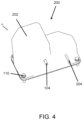
- FIG. 4 illustrates a perspective view of the tilt measurement system 200 secured inside an outer casing 202, in accordance with an example of the present subject matter.
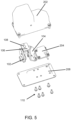
- FIG. 5 illustrates an exploded view of the tilt measurement system 200, in accordance with an example of the present subject matter.
- FIG. 6 illustrates a perspective view of the tilt measurement system 200 without the outer casing 202, in accordance with an example of the present subject matter.
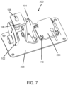
- FIG. 7 illustrates an isometric view of the tilt measurement system 200 without the outer casing 202, in accordance with an example of the present subject matter.
- FIGS. 4 , 5 , 6 and 7 have been discussed in conjunction with each other.
- the tilt measurement system 200 measures an angle of tilt of a component.
- the component may be a part of a mechanical device having the tilt measurement system 200 mounted thereto.
- the component may be a part of a vehicle, such as the chassis.
- the angular measurement device 100 may be mounted to one side of the chassis and the angular rate measurement sensor 204 may be mounted to another side of the chassis. In such case, there is a possibility that the measured values from the angular measurement device 100 and the angular rate measurement sensor 204 are different. Therefore, the angular measurement device 100 and the angular rate measurement sensor 204 will have to be calibrated.
- the component may be a part of the tilt measurement system 200.
- the component may be a base plate 208 onto which the angular measurement device 100 and the angular rate measurement sensor204 are mounted.
- the angular measurement device 100 and the angular rate measurement sensor 204 measure the change in orientation of the same element. i.e. the base plate 208. Therefore, there is no need to calibrate the sensors.
- the tilt measurement system 200 includes an outer casing 202 mounted over a base plate 210.
- the outer casing 202 restricts the entry of unwanted elements, such as moisture.
- the fixable base 106 is be mounted to the component.
- the fixable base 106and component are permanently attached to each other using different joining techniques, such as welding.
- the fixable base 106 can be fixedly mounted to the component using temporary fastening means, such as fasteners 110.
- the angular rate measurement sensor 204 is mounted to the component.
- the angular rate measurement sensor 204 measures rate of change of orientation of the component.
- the angular rate measurement sensor 204 may bea microelectromechanical systems (MEMS) gyroscopic sensor.
- the tilt measurement system 200 further includes a control unit 206 operably coupled to the angular rate measurement sensor 204 and the angular position sensor 104.
- the control unit 206 receives inputs from the angular position sensor 104 and the angular rate measurement sensor 204, and then processes the received inputs to estimate the angle of tilt of the component with respect to a reference datum, for example, ground. Therefore, the angle of tilt of the component can be estimated using 2 sensors only.
- the computational resources required to estimate the orientation is considerably less. Accordingly, the orientation estimation technique is also cost effective. Further, the orientation of a mechanical device onto which the tilt measurement system 200 is mounted on can also be estimated.
- the mechanical device may be a robot, a drone, an automobile, etc.
- control unit 206 can be implemented as a microcontroller, a microcomputer, and/or any other device that manipulates signals based on operational instructions.
- the control unit 206 can include a processor and a device memory.
- the processor can be a single processing unit or a number of units, all of which could include multiple computing units.
- the processor may be implemented as one or more microprocessors, microcomputers, microcontrollers, digital signal processors, central processing units, state machines, logic circuitries, and/or any devices that manipulate signals, based on operational instructions.
- the processor(s) is provided to fetch and execute computer-readable instructions stored in the device memory.
- the device memory may be coupled to the processor and can include any computer-readable medium known in the art including, for example, volatile memory, such as Static-Random Access Memory (SRAM) and Dynamic-Random Access Memory (DRAM), and/or non-volatile memory, such as Read Only Memory (ROM), erasable programmable ROM, flash memories, hard disks, optical disks, and magnetic tapes.
- volatile memory such as Static-Random Access Memory (SRAM) and Dynamic-Random Access Memory (DRAM)
- non-volatile memory such as Read Only Memory (ROM), erasable programmable ROM, flash memories, hard disks, optical disks, and magnetic tapes.
- FIG. 8 illustrates a schematic block diagram of the tilt measurement system 200 for estimating angle of tilt of the component, in accordance with an example of the present subject matter.
- the angular position sensor 104 measures the angular displacement of the suspended element 102 from the neutral position with respect to the fixable base 106.
- the angular rate measurement sensor 204 measures the rate of change of orientation of the component.
- the control unit 206 receives inputs from the angular position sensor 104 and the angular rate measurement sensor 204. Based on the received inputs, the control unit 206 estimates the angle of tilt of the component with respect to a reference datum, for example, ground.
- Fig. 9 illustrates a method 300 for estimating angle of tilt of the component, in accordance with one implementation of the present subject matter.
- the angular position sensor 104 and the angular rate measurement sensor 204 detects that the component has tilted from its original position.
- the angular position sensor 104 measures the angular displacement of the suspended element 102 from the neutral position with respect to the fixable base 106.
- the angular rate measurement sensor 204 measures the rate of change of orientation of the component.
- the control unit 206 receives a first set of inputs, based on the displacement of the suspended element 102 with respect to the fixable base 106, from the angular position sensor 104.
- the control unit 206 receives a second set of inputs, based on the rate of change of orientation of the component, from the angular rate measurement sensor 204. Based on the received inputs, the control unit 206 estimates the angle of tilt of the component with respect to a reference datum, for example, ground.
- the data transmitted by the angular position sensor 104 and the angular rate measurement sensor 204 may be different from the actual values due to vibrations and noise.
- the inputs received from the angular position sensor 104 and the angular rate measurement sensor 204 may include errors.
- the control unit 206 may employ different sensor fusion algorithms to process the data received from the angular position sensor 104 and the angular rate measurement sensor 204. For instance, the control unit 206 may employ Bayesian filter algorithm or Fusion filter algorithm to process the first and second set of inputs.
- the control unit 206 conditions the received first set of inputs and the second set of inputs. At block 308, the control unit 206 estimates the error associated with the first set of inputs using any sensor fusion algorithm. At block 310, the control unit 206 employs the sensor fusion algorithm to estimate the error associated with the second set of inputs. At block 312, the control unit 206 eliminates the estimated errors to obtain a fused output using the sensor fusion algorithms. At block 314, the control unit 206 calculates the angle of tilt of the component with respect to a reference datum based on the fused output.
- Fig. 10 illustrates a schematic block diagram of a tilt measurement system 200 for estimating angle of tilt of a component, in accordance with another example of the present subject matter.
- the tilt measurement system 200 may also include an accelerometer sensor 400 operably coupled to the control unit 206.
- the accelerometer sensor 400 measures the angle of tilt by measuring component of acceleration due to gravity along different axes.
- the control unit 206 receives a third set of inputs from the accelerometer sensor 400. Further, the control unit 206 may estimate the angle of tilt of the component using at least one of the first, second or third set of inputs.
- the third sensor i.e. the accelerometer sensor 400, is only used in situations which require highly accurate estimation of the angle of tilt.
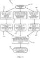
- FIG. 11 illustrates a method 500 for estimating angle of tilt of the component, in accordance with another implementation of the present subject matter.
- the tilt measurement system 200 may include the accelerometer sensor 400.
- the angular position sensor 104, the angular rate measurement sensor 204 and the accelerometer sensor (400) detects that the component has tilted from its original position.
- the angular position sensor 104 measures the angular displacement of the suspended element 102 from the neutral position with respect to the fixable base 106.
- the angular rate measurement sensor 204 measures the rate of change of orientation of the component.
- the accelerometer sensor 400 measures the component of acceleration due to gravity along different axes.
- the control unit 206 receives a first set of inputs, based on the displacement of the suspended element 102 with respect to the fixable base 106, from the angular position sensor 104.
- the control unit 206 receives a second set of inputs, based on the rate of change of orientation of the component, from the angular rate measurement sensor 204.
- the control unit 206 receives a third set of inputs, based on the component of acceleration due to gravity along different axes, from the accelerometer sensor 400. Based on the received inputs, the control unit 206 estimates the angle of tilt of the component with respect to a reference datum, for example, ground.
- the control unit 206 may employ different sensor fusion algorithms, such as Bayesian filter algorithm or Fusion filter algorithm, to process the first, second, and third set of inputs to process the data received from the sensors.
- the control unit 206 processes and conditions the first, set and third set of inputs using the sensor fusion algorithm.
- the control unit 206 estimates the error associated with the first set of inputs.
- the control unit 206 estimates the error associated with the second set of inputs.
- the control unit 206 estimates the error associated with the third set of inputs.
- the control unit 206 obtains a fused output by eliminating the errors associated with the first, second and third set of inputs.
- the control unit 206 estimates the angle of tilt of the component with respect to a reference datum, for example, ground.
- the methods 300, 500 may be described in the general context of computer executable instructions.
- computer executable instructions can include routines, programs, objects, components, data structures, procedures, engines, functions, etc., that perform particular functions or employ particular abstract data types.
- the methods 300, 500 may also be practiced in a distributed computing environment where functions are performed by remote processing devices that are linked through a communications network.
- computer executable instructions may be located in both local and remote computer storage media, including memory storage devices.
- FIG. 12 illustrates a perspective view of a vehicle 600 having the tilt measurement system 200 mounted thereto, in accordance with an example of the present subject matter, whereas FIG. 13 illustrates an isometric view of the vehicle 600.
- FIGS. 12 and 13 have been discussed in conjunction with each other.
- the vehicle 600 includes a vehicular frame 602, a pivot tube 604, a front suspension 606, a front wheel 608, a handle bar 610, a rear suspension 612 and a rear wheel 614.
- the control unit 206 can determine the angle of tilt of the vehicle 600.
- the tilt measurement system 200 is located at a distance of 400 millimeter (mm) to 900 mm from the ground surface.
- the axis of suspended element's shaft is aligned with the axis of the vehicle 600 along which the tilt needs to be measured.
- the suspended element 102 may have a mass between 50 to 500 grams and a length of 2 mm to 50 mm.
- the tilt measurement system 200 may be mounted to the top most position on the device, such as the vehicle 600.
- FIG. 14 illustrates a graph representing the errors associated in determining the angle of tilt of the component.
- the inputs received from the angular position sensor 104 and the angular rate measurement sensor 204 may include errors due to vibrations and noise.
- Line 702 represents angle of tilt of the component estimated based on the inputs received from the angular position sensor 104.
- Line 704 represents angle of tilt of the component estimated based on the inputs received from the angular rate measurement sensor 204.
- the control unit 206 may employ a sensor fusion algorithm to estimate the errors associated with the inputs received from the sensors. Further, the control unit 206 obtains a fused output after eliminating the errors associated with the received inputs. The control unit 206 estimates the angle of tilt of the component based on the obtained fused output.
- FIG. 15 illustrates a graph representing varies values of the angle of tilt of the component with the tilt measurement system 200 mounted to the vehicle 600 at varied heights from the ground.
- the tilt measurement system 200 includes a suspended element 102 having a mass of 500 grams.
- Line 802 represents actual value of the angle of tilt of the component.
- Line 804 represents the angle of tilt of the component when the tilt measurement system 200 is mounted at a height of 500 mm from the ground.
- Line 806 represents the angle of tilt of the component when the tilt measurement system 200 is mounted at a height of 300 mm from the ground.
- Line 808 represents the angle of tilt of the component when the tilt measurement system 200 is mounted at a height of 200 mm from the ground.
- Line 810 represents the angle of tilt of the component when the tilt measurement system 200 is mounted at a height of 100 mm from the ground.
- the difference between the estimated value of the angle of tilt of the component and the actual value decreases as the height of the tilt measurement system 200 from the ground increases. Therefore, the present subject matter also envisages that when the tilt measurement system 200 or at least the angular measurement device 100 is mounted on the vehicle 600 to be at a distance of 400 mm to 900 mm from the ground surface, the performance of the tilt measurement system 200 and/or the angular measurement device 100 is optimized.
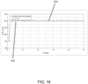
- FIG. 16 represents a graph illustrating the difference between the angular displacement of the suspended element 102 when the suspended element 102 is provided with and without pre-determined damping, as has been discussed previously.
- Line 902 represents the angular displacement of the suspended element 102 when no pre-determined damping is provided to the suspended element 102. Without damping, the angular displacement of the suspended element 102 may be affected due to undesirable oscillations which may occur due to inertia of the suspended element 102. Therefore, line 902 is not the actual value of the angular displacement of the suspended element 102.
- Line 904 represents actual value of the angular displacement of the suspended element 102.
- a pre-determined damping is provided to the suspended element 102, the undesirable effects caused due to inertia of the suspended element 102 can be negated. Also, by damping the suspended element 102, adverse effects of vibrations and noise can be eliminated. Therefore, a pre-determined damping is provided to the suspended element so that the value obtained substantially conforms with the actual value of the angular displacement of the suspended element. Accordingly, the angle of tilt of the fixable base 106 or the component can be determined based on the actual value of the angular displacement of the suspended element 102 and, hence, can be accurately determined, for instance, despite the presence of vibrations in the mechanical system.
Landscapes
- Physics & Mathematics (AREA)
- Engineering & Computer Science (AREA)
- General Physics & Mathematics (AREA)
- Radar, Positioning & Navigation (AREA)
- Remote Sensing (AREA)
- Length Measuring Devices With Unspecified Measuring Means (AREA)
Claims (14)
- Neigungsmesssystem (200) zum Abschätzen des Neigungswinkels eines Bauteils, wobei das Neigungsmesssystem (200) Folgendes umfasst:
eine Winkelmessvorrichtung (100) mit:eine fixierbare Basis (106), die an dem Bauteil befestigt ist;ein aufgehängtes Element (102), das an der fixierbaren Basis (106) montiert ist, wobei das aufgehängte Element (102) in der Lage ist, eine oszillierende Bewegung in Bezug auf die fixierbare Basis (106) durchzuführen; undeinen Winkelpositionssensor (104), der betriebsmäßig mit dem aufgehängten Element (102) gekoppelt ist, um eine Winkelverschiebung des aufgehängten Elements (102) aus einer neutralen Position des aufgehängten Elements (102), gemessen in Bezug auf die fixierbare Basis (106), zu messen;wobei das Neigungssystem dadurch gekennzeichnet ist, dass es umfasst:einen Winkelgeschwindigkeitsmesssensor (204), der an dem Bauteil angebracht ist, wobei der Winkelgeschwindigkeitsmesssensor (204) die Änderungsgeschwindigkeit der Ausrichtung des Bauteils misst; undeine Steuereinheit (206), die betriebsmäßig mit dem Winkelpositionssensor (104) und dem Winkelgeschwindigkeitsmesssensor (204) gekoppelt ist, wobei die Steuereinheit (206) konfiguriert ist, um:einen ersten Satz von Eingaben von dem Winkelpositionssensor (104) zu empfangen;einen zweiten Satz von Eingaben von dem Winkelgeschwindigkeitsmesssensor (204) zu empfangen; undeinen Neigungswinkel des Bauteils in Bezug auf einen Referenzwert auf der Grundlage des ersten Satzes von Eingaben und des zweiten Satzes von Eingaben zu schätzen. - Neigungsmesssystem (200) nach Anspruch 1, wobei die Neutralstellung des aufgehängten Elements (102) die Gleichgewichtsstellung ist.
- Neigungsmesssystem (200) nach Anspruch 1, wobei die Winkelmessvorrichtung (100) ferner eine Dämpfungseinheit (108) zur Dämpfung der Schwingungsbewegung des aufgehängten Elements (102) umfasst.
- Neigungsmesssystem (200) nach Anspruch 1, wobei das aufgehängte Element (102) ein schwimmendes Pendel ist.
- Neigungsmesssystem (200) nach Anspruch 1, wobei der Winkelpositionssensor (104) ein Potentiometer, ein optischer Sensor, ein Encoder oder ein Halleffektsensor ist.
- Neigungsmesssystem (200) nach Anspruch 1, wobei die Steuereinheit (206) ferner einen Bayes'schen Filter umfasst, wobei der Bayes'sche Filter die Steuereinheit (206) veranlasst,:einen Fehler zu schätzen, der mit dem ersten Satz von Eingaben verbunden ist;einen Fehler zu schätzen, der mit dem zweiten Satz von Eingaben verbunden ist;Eliminieren der Fehler, die mit dem ersten und zweiten Satz von Eingaben verbunden sind, um eine fusionierte Ausgabe zu erhalten; undSchätzung des Neigungswinkels des Bauteils in Übereinstimmung mit der fusionierten Ausgabe.
- Neigungsmesssystem (200) nach Anspruch 1, wobei die Steuereinheit (206) ferner einen Fusionsfilter umfasst, wobei der Fusionsfilter die Steuereinheit (206) veranlasst,:einen Fehler abzuschätzen, der mit dem ersten Satz von Eingaben verbunden isteinen Fehler abzuschätzen, der mit dem zweiten Satz von Eingaben verbunden ist;die mit dem ersten und zweiten Satz von Eingaben verbundenen Fehler zu eliminieren, um eine fusionierte Ausgabe zu erhalten; undSchätzung des Neigungswinkels des Bauteils in Übereinstimmung mit der fusionierten Ausgabe.
- Neigungsmesssystem (200) nach Anspruch 1, wobei der Winkelgeschwindigkeitsmesssensor (204) ein MEMS-Gyroskopsensor ist.
- Neigungsmesssystem (200) nach Anspruch 1, das ferner einen Beschleunigungssensor (400) umfasst, der betriebsmäßig mit der Steuereinheit (206) gekoppelt ist, wobei die Steuereinheit (206) dazu dient,:einen dritten Satz von Eingaben von dem Beschleunigungssensor (400) zu empfangen; undden Neigungswinkel des Bauteils auf der Grundlage des dritten Satzes von Eingaben zu schätzen.
- Fahrzeug (600), das einen Fahrzeugrahmen (602) umfasst, an dem ein Neigungsmesssystem (200) nach einem der Ansprüche 1 bis 9 angebracht ist.
- Fahrzeug (600) nach Anspruch 10, wobei das Neigungsmesssystem (200) in einem Abstand von 400 mm bis 900 mm vom Boden angeordnet ist.
- Verfahren zum Messen des Neigungswinkels eines Bauteils, wobei das Verfahren umfasst:Bestimmen, durch einen Winkelpositionssensor (104), einer Winkelverschiebung eines aufgehängten Elements (102), das betriebsmäßig mit dem Winkelpositionssensor (104) gekoppelt ist, wobei der Winkelpositionssensor (104) und das aufgehängte Element (102) an einer an dem Bauteil befestigten fixierbaren Basis (106) angebracht sind;wobei das Verfahren dadurch gekennzeichnet ist, dass es ferner die folgenden Schritte umfasst:Bestimmen der Änderungsrate der Orientierung der fixierbaren Basis (106) durch einen Winkelgeschwindigkeitsmesssensor (204);Empfangen, durch eine Steuereinheit (206), die betriebsmäßig mit dem Winkelpositionssensor (104) gekoppelt ist, eines ersten Satzes von Eingaben, die auf der Winkelverschiebung des aufgehängten Elements (102) basieren;Empfangen, durch die Steuereinheit (206), die betriebsmäßig mit dem Winkelgeschwindigkeitsmesssensor (204) gekoppelt ist, eines zweiten Satzes von Eingaben, basierend auf der Änderungsrate der Orientierung des Bauteils; undVerarbeiten des ersten und zweiten Satzes von Eingaben durch die Steuereinheit (206), um den Neigungswinkel des Bauteils in Bezug auf einen Referenzwert zu schätzen.
- Verfahren nach Anspruch 12, wobei das Verfahren umfasst:Schätzen eines Fehlers, der mit dem ersten Satz von Eingaben verbunden ist;Schätzen eines Fehlers, der mit dem zweiten Satz von Eingaben verbunden ist;Eliminieren der Fehler, die mit dem ersten und zweiten Satz von Eingaben verbunden sind, um eine fusionierte Ausgabe zu erhalten; undSchätzen des Neigungswinkels der fixierbaren Basis (106) in Übereinstimmung mit der fusionierten Ausgabe.
- Verfahren nach Anspruch 12, wobei das Verfahren umfasst:Empfangen eines dritten Satzes von Eingaben von dem Beschleunigungssensor (400); undVerarbeiten des dritten Satzes von Eingaben durch die Steuereinheit (206), um den Neigungswinkel des Bauteils zu schätzen.
Applications Claiming Priority (1)
| Application Number | Priority Date | Filing Date | Title |
|---|---|---|---|
| IN202141012940 | 2021-03-24 |
Publications (2)
| Publication Number | Publication Date |
|---|---|
| EP4063786A1 EP4063786A1 (de) | 2022-09-28 |
| EP4063786B1 true EP4063786B1 (de) | 2025-05-21 |
Family
ID=80787432
Family Applications (1)
| Application Number | Title | Priority Date | Filing Date |
|---|---|---|---|
| EP22162608.8A Active EP4063786B1 (de) | 2021-03-24 | 2022-03-17 | Neigungsschätzung |
Country Status (3)
| Country | Link |
|---|---|
| EP (1) | EP4063786B1 (de) |
| CN (1) | CN115127521A (de) |
| ES (1) | ES3035752T3 (de) |
Family Cites Families (7)
| Publication number | Priority date | Publication date | Assignee | Title |
|---|---|---|---|---|
| US5112126A (en) * | 1990-07-27 | 1992-05-12 | Chevron Research & Technology Company | Apparatuses and methods for making geophysical measurements useful in determining the deflection of the vertical |
| JP4465607B2 (ja) * | 2004-12-27 | 2010-05-19 | 東洋電装株式会社 | 傾倒センサ |
| US7325322B2 (en) * | 2005-02-01 | 2008-02-05 | Delphi Technologies, Inc. | Electric park brake inclinometer |
| JP5038960B2 (ja) * | 2008-03-31 | 2012-10-03 | 公益財団法人鉄道総合技術研究所 | 振子車両の車体傾斜角の制御方法及び振子車両の車体傾斜角の制御システム |
| CN108871182B (zh) * | 2018-06-05 | 2021-03-26 | 重庆电子工程职业学院 | 一种摩托车倾斜角度传感器测试装置 |
| CN109655055B (zh) * | 2018-11-07 | 2020-11-20 | 深圳技术大学(筹) | 一种轨检机器人的定位方法及装置 |
| CN111397577B (zh) * | 2020-02-21 | 2021-11-12 | 浙江运达风电股份有限公司 | 一种倾角传感器和陀螺仪融合的塔架监测系统及方法 |
-
2022
- 2022-03-14 CN CN202210249197.7A patent/CN115127521A/zh active Pending
- 2022-03-17 EP EP22162608.8A patent/EP4063786B1/de active Active
- 2022-03-17 ES ES22162608T patent/ES3035752T3/es active Active
Also Published As
| Publication number | Publication date |
|---|---|
| CN115127521A (zh) | 2022-09-30 |
| ES3035752T3 (en) | 2025-09-08 |
| EP4063786A1 (de) | 2022-09-28 |
Similar Documents
| Publication | Publication Date | Title |
|---|---|---|
| JP4170284B2 (ja) | 移動物体の進行方向の推定方法およびシステム | |
| US8185309B2 (en) | Enhanced inertial system performance | |
| KR100651549B1 (ko) | 이동체의 속력 측정 장치 및 방법 | |
| US8019542B2 (en) | Heading stabilization for aided inertial navigation systems | |
| Wei et al. | A robust adaptive error state Kalman filter for MEMS IMU attitude estimation under dynamic acceleration | |
| KR101160630B1 (ko) | 주행 모드 판별법, 상기 주행 모드 판별을 이용한 항법 시스템 및 그 제공방법 | |
| CN114526731A (zh) | 一种基于助力车的惯性组合导航方向定位方法 | |
| JP6981459B2 (ja) | センサ誤差補正装置 | |
| EP3183394A1 (de) | Erdbewegungsmaschine mit gewichtetem zustandsberechner | |
| KR100520144B1 (ko) | 가속도계를 이용한 이동체의 속력측정 및 그 장치 | |
| CN108871323A (zh) | 一种低成本惯性传感器在机动环境下的高精度导航方法 | |
| KR102038482B1 (ko) | 관성 센서 향상 | |
| EP4063786B1 (de) | Neigungsschätzung | |
| KR102380586B1 (ko) | 오차 추정 장치, 오차 추정 방법 및 항법 시스템 | |
| CN112082544A (zh) | 一种imu数据补偿方法及装置 | |
| US11906542B2 (en) | System for checking an inertial measurement unit | |
| WO2018012064A1 (ja) | 角度計測装置 | |
| Huttner et al. | Offset and Misalignment Estimation for the Online Calibration of an MEMS-IMU Using FIR-Filter Modulating Functions. | |
| JP2015004593A (ja) | ナビゲーション装置 | |
| CN114762002A (zh) | 用于移动设备的摄像机系统、用于定位一个摄像机的方法、以及用于定位多个摄像机的方法 | |
| US11796318B2 (en) | Rotation measurement system using Coriolis and Euler forces | |
| KR101990404B1 (ko) | 발사관의 롤 회전을 이용한 관성항법장치 비정렬각 산출 방법 및 그 장치 | |
| JP3783061B1 (ja) | 傾斜角と並進加速度の検出方法および検出装置 | |
| JP2016031283A (ja) | 角速度センサ装置および角速度センサ補正方法 | |
| JP7238490B2 (ja) | センサ誤差補正装置、及びセンサ誤差補正プログラム |
Legal Events
| Date | Code | Title | Description |
|---|---|---|---|
| PUAI | Public reference made under article 153(3) epc to a published international application that has entered the european phase |
Free format text: ORIGINAL CODE: 0009012 |
|
| STAA | Information on the status of an ep patent application or granted ep patent |
Free format text: STATUS: THE APPLICATION HAS BEEN PUBLISHED |
|
| AK | Designated contracting states |
Kind code of ref document: A1 Designated state(s): AL AT BE BG CH CY CZ DE DK EE ES FI FR GB GR HR HU IE IS IT LI LT LU LV MC MK MT NL NO PL PT RO RS SE SI SK SM TR |
|
| STAA | Information on the status of an ep patent application or granted ep patent |
Free format text: STATUS: REQUEST FOR EXAMINATION WAS MADE |
|
| 17P | Request for examination filed |
Effective date: 20230320 |
|
| RBV | Designated contracting states (corrected) |
Designated state(s): AL AT BE BG CH CY CZ DE DK EE ES FI FR GB GR HR HU IE IS IT LI LT LU LV MC MK MT NL NO PL PT RO RS SE SI SK SM TR |
|
| REG | Reference to a national code |
Ref country code: DE Ref legal event code: R079 Free format text: PREVIOUS MAIN CLASS: G01C0009140000 Ipc: G01C0009160000 Ref country code: DE Ref legal event code: R079 Ref document number: 602022014829 Country of ref document: DE Free format text: PREVIOUS MAIN CLASS: G01C0009140000 Ipc: G01C0009160000 |
|
| RIC1 | Information provided on ipc code assigned before grant |
Ipc: G01C 9/14 20060101ALI20241024BHEP Ipc: G01C 9/16 20060101AFI20241024BHEP |
|
| GRAP | Despatch of communication of intention to grant a patent |
Free format text: ORIGINAL CODE: EPIDOSNIGR1 |
|
| STAA | Information on the status of an ep patent application or granted ep patent |
Free format text: STATUS: GRANT OF PATENT IS INTENDED |
|
| INTG | Intention to grant announced |
Effective date: 20241212 |
|
| GRAS | Grant fee paid |
Free format text: ORIGINAL CODE: EPIDOSNIGR3 |
|
| GRAA | (expected) grant |
Free format text: ORIGINAL CODE: 0009210 |
|
| STAA | Information on the status of an ep patent application or granted ep patent |
Free format text: STATUS: THE PATENT HAS BEEN GRANTED |
|
| AK | Designated contracting states |
Kind code of ref document: B1 Designated state(s): AL AT BE BG CH CY CZ DE DK EE ES FI FR GB GR HR HU IE IS IT LI LT LU LV MC MK MT NL NO PL PT RO RS SE SI SK SM TR |
|
| REG | Reference to a national code |
Ref country code: GB Ref legal event code: FG4D |
|
| REG | Reference to a national code |
Ref country code: CH Ref legal event code: EP |
|
| REG | Reference to a national code |
Ref country code: DE Ref legal event code: R096 Ref document number: 602022014829 Country of ref document: DE |
|
| REG | Reference to a national code |
Ref country code: IE Ref legal event code: FG4D |
|
| REG | Reference to a national code |
Ref country code: ES Ref legal event code: FG2A Ref document number: 3035752 Country of ref document: ES Kind code of ref document: T3 Effective date: 20250908 |
|
| REG | Reference to a national code |
Ref country code: NL Ref legal event code: MP Effective date: 20250521 |
|
| PG25 | Lapsed in a contracting state [announced via postgrant information from national office to epo] |
Ref country code: PT Free format text: LAPSE BECAUSE OF FAILURE TO SUBMIT A TRANSLATION OF THE DESCRIPTION OR TO PAY THE FEE WITHIN THE PRESCRIBED TIME-LIMIT Effective date: 20250922 Ref country code: FI Free format text: LAPSE BECAUSE OF FAILURE TO SUBMIT A TRANSLATION OF THE DESCRIPTION OR TO PAY THE FEE WITHIN THE PRESCRIBED TIME-LIMIT Effective date: 20250521 |
|
| REG | Reference to a national code |
Ref country code: LT Ref legal event code: MG9D |
|
| PG25 | Lapsed in a contracting state [announced via postgrant information from national office to epo] |
Ref country code: GR Free format text: LAPSE BECAUSE OF FAILURE TO SUBMIT A TRANSLATION OF THE DESCRIPTION OR TO PAY THE FEE WITHIN THE PRESCRIBED TIME-LIMIT Effective date: 20250822 Ref country code: NO Free format text: LAPSE BECAUSE OF FAILURE TO SUBMIT A TRANSLATION OF THE DESCRIPTION OR TO PAY THE FEE WITHIN THE PRESCRIBED TIME-LIMIT Effective date: 20250821 |
|
| PG25 | Lapsed in a contracting state [announced via postgrant information from national office to epo] |
Ref country code: PL Free format text: LAPSE BECAUSE OF FAILURE TO SUBMIT A TRANSLATION OF THE DESCRIPTION OR TO PAY THE FEE WITHIN THE PRESCRIBED TIME-LIMIT Effective date: 20250521 Ref country code: NL Free format text: LAPSE BECAUSE OF FAILURE TO SUBMIT A TRANSLATION OF THE DESCRIPTION OR TO PAY THE FEE WITHIN THE PRESCRIBED TIME-LIMIT Effective date: 20250521 |
|
| PG25 | Lapsed in a contracting state [announced via postgrant information from national office to epo] |
Ref country code: BG Free format text: LAPSE BECAUSE OF FAILURE TO SUBMIT A TRANSLATION OF THE DESCRIPTION OR TO PAY THE FEE WITHIN THE PRESCRIBED TIME-LIMIT Effective date: 20250521 |
|
| PG25 | Lapsed in a contracting state [announced via postgrant information from national office to epo] |
Ref country code: HR Free format text: LAPSE BECAUSE OF FAILURE TO SUBMIT A TRANSLATION OF THE DESCRIPTION OR TO PAY THE FEE WITHIN THE PRESCRIBED TIME-LIMIT Effective date: 20250521 |
|
| PG25 | Lapsed in a contracting state [announced via postgrant information from national office to epo] |
Ref country code: RS Free format text: LAPSE BECAUSE OF FAILURE TO SUBMIT A TRANSLATION OF THE DESCRIPTION OR TO PAY THE FEE WITHIN THE PRESCRIBED TIME-LIMIT Effective date: 20250821 |
|
| PG25 | Lapsed in a contracting state [announced via postgrant information from national office to epo] |
Ref country code: IS Free format text: LAPSE BECAUSE OF FAILURE TO SUBMIT A TRANSLATION OF THE DESCRIPTION OR TO PAY THE FEE WITHIN THE PRESCRIBED TIME-LIMIT Effective date: 20250921 |
|
| PG25 | Lapsed in a contracting state [announced via postgrant information from national office to epo] |
Ref country code: LV Free format text: LAPSE BECAUSE OF FAILURE TO SUBMIT A TRANSLATION OF THE DESCRIPTION OR TO PAY THE FEE WITHIN THE PRESCRIBED TIME-LIMIT Effective date: 20250521 |
|
| REG | Reference to a national code |
Ref country code: AT Ref legal event code: MK05 Ref document number: 1797074 Country of ref document: AT Kind code of ref document: T Effective date: 20250521 |
|
| PG25 | Lapsed in a contracting state [announced via postgrant information from national office to epo] |
Ref country code: DK Free format text: LAPSE BECAUSE OF FAILURE TO SUBMIT A TRANSLATION OF THE DESCRIPTION OR TO PAY THE FEE WITHIN THE PRESCRIBED TIME-LIMIT Effective date: 20250521 Ref country code: SM Free format text: LAPSE BECAUSE OF FAILURE TO SUBMIT A TRANSLATION OF THE DESCRIPTION OR TO PAY THE FEE WITHIN THE PRESCRIBED TIME-LIMIT Effective date: 20250521 Ref country code: AT Free format text: LAPSE BECAUSE OF FAILURE TO SUBMIT A TRANSLATION OF THE DESCRIPTION OR TO PAY THE FEE WITHIN THE PRESCRIBED TIME-LIMIT Effective date: 20250521 |
|
| PG25 | Lapsed in a contracting state [announced via postgrant information from national office to epo] |
Ref country code: CZ Free format text: LAPSE BECAUSE OF FAILURE TO SUBMIT A TRANSLATION OF THE DESCRIPTION OR TO PAY THE FEE WITHIN THE PRESCRIBED TIME-LIMIT Effective date: 20250521 |
|
| PG25 | Lapsed in a contracting state [announced via postgrant information from national office to epo] |
Ref country code: EE Free format text: LAPSE BECAUSE OF FAILURE TO SUBMIT A TRANSLATION OF THE DESCRIPTION OR TO PAY THE FEE WITHIN THE PRESCRIBED TIME-LIMIT Effective date: 20250521 |
|
| PG25 | Lapsed in a contracting state [announced via postgrant information from national office to epo] |
Ref country code: SK Free format text: LAPSE BECAUSE OF FAILURE TO SUBMIT A TRANSLATION OF THE DESCRIPTION OR TO PAY THE FEE WITHIN THE PRESCRIBED TIME-LIMIT Effective date: 20250521 |
|
| REG | Reference to a national code |
Ref country code: DE Ref legal event code: R097 Ref document number: 602022014829 Country of ref document: DE |
|
| PLBE | No opposition filed within time limit |
Free format text: ORIGINAL CODE: 0009261 |
|
| STAA | Information on the status of an ep patent application or granted ep patent |
Free format text: STATUS: NO OPPOSITION FILED WITHIN TIME LIMIT |
|
| REG | Reference to a national code |
Ref country code: CH Ref legal event code: L10 Free format text: ST27 STATUS EVENT CODE: U-0-0-L10-L00 (AS PROVIDED BY THE NATIONAL OFFICE) Effective date: 20260402 |
|
| PGFP | Annual fee paid to national office [announced via postgrant information from national office to epo] |
Ref country code: DE Payment date: 20260319 Year of fee payment: 5 |
|
| PGFP | Annual fee paid to national office [announced via postgrant information from national office to epo] |
Ref country code: IT Payment date: 20260324 Year of fee payment: 5 |
|
| PGFP | Annual fee paid to national office [announced via postgrant information from national office to epo] |
Ref country code: FR Payment date: 20260323 Year of fee payment: 5 |
|
| 26N | No opposition filed |
Effective date: 20260224 |