EP4063759B1 - Systeme de chauffage d'eau - Google Patents
Systeme de chauffage d'eau Download PDFInfo
- Publication number
- EP4063759B1 EP4063759B1 EP22163141.9A EP22163141A EP4063759B1 EP 4063759 B1 EP4063759 B1 EP 4063759B1 EP 22163141 A EP22163141 A EP 22163141A EP 4063759 B1 EP4063759 B1 EP 4063759B1
- Authority
- EP
- European Patent Office
- Prior art keywords
- box
- wall
- compartment
- refrigerant
- heat pump
- Prior art date
- Legal status (The legal status is an assumption and is not a legal conclusion. Google has not performed a legal analysis and makes no representation as to the accuracy of the status listed.)
- Active
Links
Images


Classifications
-
- F—MECHANICAL ENGINEERING; LIGHTING; HEATING; WEAPONS; BLASTING
- F24—HEATING; RANGES; VENTILATING
- F24H—FLUID HEATERS, e.g. WATER OR AIR HEATERS, HAVING HEAT-GENERATING MEANS, e.g. HEAT PUMPS, IN GENERAL
- F24H4/00—Fluid heaters characterised by the use of heat pumps
- F24H4/02—Water heaters
- F24H4/04—Storage heaters
-
- F—MECHANICAL ENGINEERING; LIGHTING; HEATING; WEAPONS; BLASTING
- F24—HEATING; RANGES; VENTILATING
- F24H—FLUID HEATERS, e.g. WATER OR AIR HEATERS, HAVING HEAT-GENERATING MEANS, e.g. HEAT PUMPS, IN GENERAL
- F24H9/00—Details
- F24H9/14—Arrangements for connecting different sections, e.g. in water heaters
- F24H9/148—Arrangements of boiler components on a frame or within a casing to build the fluid heater, e.g. boiler
-
- F—MECHANICAL ENGINEERING; LIGHTING; HEATING; WEAPONS; BLASTING
- F24—HEATING; RANGES; VENTILATING
- F24H—FLUID HEATERS, e.g. WATER OR AIR HEATERS, HAVING HEAT-GENERATING MEANS, e.g. HEAT PUMPS, IN GENERAL
- F24H9/00—Details
- F24H9/16—Arrangements for water drainage
- F24H9/17—Means for retaining water leaked from heaters
-
- F—MECHANICAL ENGINEERING; LIGHTING; HEATING; WEAPONS; BLASTING
- F24—HEATING; RANGES; VENTILATING
- F24H—FLUID HEATERS, e.g. WATER OR AIR HEATERS, HAVING HEAT-GENERATING MEANS, e.g. HEAT PUMPS, IN GENERAL
- F24H9/00—Details
- F24H9/20—Arrangement or mounting of control or safety devices
- F24H9/2007—Arrangement or mounting of control or safety devices for water heaters
- F24H9/2014—Arrangement or mounting of control or safety devices for water heaters using electrical energy supply
- F24H9/2021—Storage heaters
-
- F—MECHANICAL ENGINEERING; LIGHTING; HEATING; WEAPONS; BLASTING
- F24—HEATING; RANGES; VENTILATING
- F24D—DOMESTIC- OR SPACE-HEATING SYSTEMS, e.g. CENTRAL HEATING SYSTEMS; DOMESTIC HOT-WATER SUPPLY SYSTEMS; ELEMENTS OR COMPONENTS THEREFOR
- F24D17/00—Domestic hot-water supply systems
- F24D17/02—Domestic hot-water supply systems using heat pumps
-
- F—MECHANICAL ENGINEERING; LIGHTING; HEATING; WEAPONS; BLASTING
- F24—HEATING; RANGES; VENTILATING
- F24D—DOMESTIC- OR SPACE-HEATING SYSTEMS, e.g. CENTRAL HEATING SYSTEMS; DOMESTIC HOT-WATER SUPPLY SYSTEMS; ELEMENTS OR COMPONENTS THEREFOR
- F24D19/00—Details
- F24D19/10—Arrangement or mounting of control or safety devices
- F24D19/1006—Arrangement or mounting of control or safety devices for water heating systems
- F24D19/1051—Arrangement or mounting of control or safety devices for water heating systems for domestic hot water
- F24D19/1054—Arrangement or mounting of control or safety devices for water heating systems for domestic hot water the system uses a heat pump
-
- F—MECHANICAL ENGINEERING; LIGHTING; HEATING; WEAPONS; BLASTING
- F24—HEATING; RANGES; VENTILATING
- F24D—DOMESTIC- OR SPACE-HEATING SYSTEMS, e.g. CENTRAL HEATING SYSTEMS; DOMESTIC HOT-WATER SUPPLY SYSTEMS; ELEMENTS OR COMPONENTS THEREFOR
- F24D2200/00—Heat sources or energy sources
- F24D2200/12—Heat pump
- F24D2200/123—Compression type heat pumps
Definitions
- the present invention relates to a water heating system, in particular domestic water, comprising a water heater and a heat pump device.
- the system comprises a water heater positioned inside the home, provided with a water tank, as well as a heat pump device, comprising in particular a compressor, a condenser, a regulator and a evaporator, part of a thermodynamic loop.
- a heat pump device comprising in particular a compressor, a condenser, a regulator and a evaporator, part of a thermodynamic loop.
- thermodynamic loop a refrigerant circulates which is set in motion and compressed in the compressor, then undergoes condensation in the condenser before being expanded in the expander and finally undergoes evaporation in the evaporator.
- the evaporator and the condenser are heat exchangers, in each of which the refrigerant partially exchanges its thermal energy with another fluid.
- the water tank of the water heater is then heated by the condenser, for example via an element wrapped around the tank.
- the refrigerant was chosen to have flammability class A1, i.e. non-flammable. This is particularly the case for R134a and R513a fluids.
- these gases have a significant, even high, effect on global warming.
- regulations have evolved to encourage the use of fluids with less impact on global warming, in particular less polluting in the sense of global warming.
- these fluids turn out to be flammable, and it is therefore absolutely necessary to protect water heating systems against any leak of this type of refrigerant outside the thermodynamic loop to avoid any risk of fire or explosion of the system which could endanger the occupants of the home as well as material property.
- This disclosure integrates new environmental constraints to limit and/or control the risks in the event of a leak of flammable refrigerant through the design of a heating system.
- a water heating system in particular domestic water heating, comprising a water heater provided with a water tank, as well as a heat pump device provided with a condenser, an evaporator, a compressor fluidly connected to each other so as to circulate a refrigerant, the heating system comprising a compartment for housing the water tank, called the water heater compartment, and a compartment for housing at least the evaporator and of the compressor, called the heat pump compartment, the system comprising at least one ignition source, and a box housing said at least one ignition source, said box preferably being arranged under a point located at the highest point of the heat pump compartment when the system is installed in a service position, characterized in that an internal volume of the box is dimensioned to collect a predetermined quantity of refrigerant in the event of a leak thereof and in that the box comprises vents for refrigerant outlet out of the box.
- the box ensures the safety of the ignition sources which are placed out of reach of the refrigerant in the event of a leak thereof.
- the box comprises a wall, called the rear wall, arranged opposite the water heater compartment, said wall being provided with an opening for the passage of the refrigerant in the event of a leak thereof, in particular in the compartment water heater.
- the box comprises means for bypassing the box by the refrigerant in the event of a leak thereof, in particular in the heat pump compartment.
- the box is delimited by a wall, called upper wall, a wall, called lower, opposite the upper wall, the upper wall being arranged above the lower wall in the service position, the box also being delimited by a wall, called the front, disposed between the upper wall and the lower wall, at least one of said walls, called curved wall, having a curvature to deflect the refrigerant away from the box, said bypass means comprising said at minus a curved wall.
- the heat pump compartment comprises a refrigerant discharge wall provided with refrigerant discharge orifices.
- the system comprises an electrical connection conduit from the heat pump compartment to the box, one end of the conduit being arranged in the heat pump compartment above a lowest height of the fluid evacuation orifices refrigerant and/or one end of the conduit on the box side being arranged below a lowest height of said at least one ignition source of the box.
- said at least one ignition source is at least one of an electric heating element and an electronic control means of the heat pump compartment.
- the box is arranged opposite the water heater compartment and/or under the heat pump compartment.
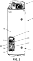
- the subject of the invention is a water heating system, in particular domestic water heating, referenced 1.
- the heated water is intended to supply a network of pipes in a home.
- system 1 is illustrated in a service position, which corresponds to a position in which the system 1 is arranged in or around the home, preferably in a sheltered room, ready to operate .
- System 1 includes in particular a heat pump device 2 as well as a water heater 3.
- the water heater 3 is provided with a water tank 4, the water of which is heated by the heat pump device 2, as will be detailed later.
- the heat pump device 2 is provided with a condenser 5, an evaporator 6, a compressor 7, and an expander (not illustrated) forming a thermodynamic loop.
- the heat pump device 2 advantageously comprises a fan 8 to force a flow of air into the evaporator 6.
- a refrigerant circulates in the thermodynamic loop, in a set of conduits 9 of the device 2.
- the air flow discharges its calories into the evaporator 6, where the refrigerant circulates, while the refrigerant exchanges all or part of the calories it contains in the condenser, which heats water stored in tank 4.
- refrigerant whose global warming power (PRG, or GWP, for “Global Warming Potential” in English) is moderate or even low, advantageously less than or equal to 750, preferably less than or equal to 150.
- PRG global warming power
- GWP Global Warming Potential
- This type of refrigerant has a gas-phase density greater than 1. In other words, when the fluid leaks out of the loop, it tends to descend by gravity.
- the system 1 comprises a first compartment 10, hereinafter called the heat pump compartment, and a second compartment 11, hereinafter called the water heater compartment.
- the heat pump compartment 10 is arranged on the water heater compartment 11 in the service position. In other words, compartment 10 forms the upper part of system 1.
- the heat pump compartment 10 comprises an envelope 12, a base 13, as well as at least the evaporator 6, the compressor 7, the fan 8, the ducts 9 mounted on the base 13.
- the envelope 12 and the base 13 form a housing for elements 6 to 9, preferably cylindrical in shape.
- the water heater compartment 11 comprises the water tank 4, the condenser 5, in the form of a coil arranged around the water tank 4, to heat the water contained in the tank 4, as well as a submerged electric heating resistance in the water tank 4 (not shown), also allowing the heating of the water in the tank 4.
- the compartment 11 comprises a covering, provided with a cylindrical longitudinal wall 15, elements 4 and 5.
- the box 20 is separate from each of the compartments 10 and 11.
- the box 20 is placed under the highest point of the heat pump device 2 in the service position of the system 1. In the illustrated embodiment, the box 20 is placed against the covering 15 of the water heater compartment 11.
- the box 20 houses an ignition source 21 which is a means of electrical control of the heating resistor and/or the heat pump device 2.
- the means 21 is in the form of a printed circuit board fitted with power electronic components.
- control means 21 constitutes what is called a source of ignition or ignition, that is to say that, due to the local heating of the air generated by the operation of the electronic components of the control means 21 or a spark linked to a leaky electrical contact, there is a risk of ignition of the refrigerant in the event of its leak.
- hot spots such as non-immersed heating elements also constitute a source of ignition. Once the auto-ignition temperature is reached, the fluid ignites, even in the absence of electrical contact type.
- the box 20 is shaped so that its internal volume is dimensioned to collect a predetermined quantity of refrigerant in the event of a leak thereof.
- the box 20 distinct from the compartments 10 and 11, and its adapted volume, ensure protection of the ignition source 21 by creating a buffer zone in the event of a leak of the refrigerant.
- the box 20 is delimited by two opposite walls, front and rear, 22, 23, two opposite walls, upper and lower, 24, 25 and two opposite walls, side, 26, 27.
- the rear wall 23 is arranged against the wall longitudinal of the covering 15 of the water heater compartment 11.
- the front and rear walls, 22, 23, extend substantially in a vertical plane (8, z).
- the rear wall 23 is provided with an opening 28 for fluid communication between the interior of the compartment 11 and the box 20.
- the opening 28 is circular.
- the longitudinal wall of the casing 15 is provided with a similar opening, which ensures that a leak of refrigerant can escape from the water heater compartment 11 into the box 20.
- the printed circuit board 27 is arranged in the upper part of the rear wall 23 while the opening 28 is arranged in the lower part of the rear wall 23.
- the internal volume of the box 20 is distributed into a volume of the part high, including the card 27 and a volume of the lower part, including the opening 28.
- the volume of the upper part is referenced V1 and the volume of the lower part V2.
- An interface I delimits the volume V1 of a on one hand and volume V2 on the other hand.
- the interface is not perfectly waterproof because junctions are available between the two volumes (cable passage in particular).
- the box 20 also includes vents 29 for evacuating refrigerant from the box 20.
- the size of the vents, their shape, their spacing, their positions in the walls of the box 20 are chosen so as to allow the flow of the entire charge of refrigerant fluid in a given duration, preferably less than 5 min.
- vents 29 are orifices drilled in the lower wall 25, of rectangular shape and parallel to each other. However, we can also consider positioning the vents in the front wall and/or side walls.
- vents are dimensioned so as to prevent access to the control means 21 by a user (test finger).
- Curved parts 30, 31 provide a junction between the upper wall 24 and each of the side walls 26, 27.
- curved walls 32, 33 provide a junction between the lower wall 25 and each of the side walls 26, 27.
- the front and rear walls 22, 23 have a generally rectangular shape whose corners are curved according to the curvature of the curved parts 30, 31, 32, 33.
- the box 20 comprises means 34 for bypassing the box 20 by the refrigerant in the event of a leak thereof.
- the bypass means 34 comprise the junction parts 30, 31 between the upper wall 24 and the side walls 26, 27.
- the fluid If refrigerant escapes from the heat pump device 2, for example from inside the heat pump compartment 10 into the interior of the water heater compartment 11, or directly from the condenser 5 of the water heater compartment 11 (arrows F2 on the Figure 6 ), the fluid accumulates by gravity in the lower part of the water heater compartment 11 until reaching the height of the opening 28, through which the fluid leaves the compartment 11 and enters the box 20. By gravity again, the fluid descends into the box 20 until it evacuates the box 20 through the vents 29.
- bypass means 34 prevents the fluid from entering the box 20.
- the system 1 also comprises a profile 35 inside which at least one electrical cable ensures the connection between the control means 21 of the heat pump device 2 and the heat pump compartment 11.
- a lower end 35-1 of the profile 35 is placed in the water heater compartment 11 and one end 35-2 of the profile 35 is placed in the heat pump compartment 10.
- Compartment 10 can also be provided with ignition sources 40. These are for example capacitors, wiring, electronic elements.
- the heat pump compartment 10 comprises a wall 36 for evacuating the refrigerant fluid provided with orifices 37 for evacuating the refrigerant fluid, also called huis.
- the wall 36 extends vertically around certain elements of the compartment 10, the evaporator 6 and the fan 8 in particular.
- the wall 34 has a section curved along an arc of a circle, for example a semi-circle.
- the wall 34 is advantageously placed on the base 13 and has a height slightly lower than the height of the envelope 12.
- the orifices 37 are identical and uniformly distributed in the wall 36.
- the invention is not limited to this arrangement and it is possible to envisage orifices of different dimensions and/or shapes. others, and/or distributed non-uniformly in the wall 36.
- the orifices 37 are arranged at the interface between the heat pump compartment 10 and the exterior of the system 1.
- a set of tubes drive the fluid towards the orifices arranged at a lower point of compartment 10 not having sources of ignition.
- the heat pump compartment 10 also includes at least one wall for protecting the ignition sources present in the compartment 10.
- the protective wall(s) have a height higher than the height of the lowest orifices.
- the compartment 10 comprises a set 38 of protective walls, including a flat flat wall 39.
- the fluid cannot reach the sources of ignition because it will be evacuated beforehand through the orifices 37, thus preventing any risk of ignition between the sources of ignition and the fluid.
- the upper end 35-2 of the profile 35 is arranged in the heat pump compartment 10 above the lowest height of the orifices 37. This arrangement makes it possible to prevent refrigerant from escaping from the compartment 10 in profile 29.
- the lower end 35-1 of the conduit 35 on the box side is arranged below a lowest height of the ignition source 21 of the box 20.
- the rear, side and upper faces being designed so as to guide the fluid around the box 20, there is a very strong limitation of the penetration of the fluid into the box 20, which ensures that the concentration of refrigerant remains lower at a threshold value which would trigger ignition under the conditions of use of system 1.
- the opening between the covering 15 and the box 20 makes it possible to avoid trapping fluid under the covering and to evacuate the fluid through the opening, then the vents of the box 20.
- the refrigerant is R290 (generic name propane).
- the total quantity of fluid in system 1 is 150g maximum, preferably 130g.
- the box 20 has dimensions of 460 mm x 235 mm x 55 mm.
- the lower zone of box 20 can contain 5g out of the 130g of the product, or 4%.
- the invention lies in the creation of a zone positioned under the highest point of the heat pump circuit in such a way that the ignition sources can be installed there without possible contact with the refrigerant resulting from any leak.
- protective walls can take various forms and in particular: waterproof compartment on the side faces with or without cowling, the upper part, tube, profile, guide etc.
Landscapes
- Engineering & Computer Science (AREA)
- Physics & Mathematics (AREA)
- Thermal Sciences (AREA)
- Chemical & Material Sciences (AREA)
- Combustion & Propulsion (AREA)
- Mechanical Engineering (AREA)
- General Engineering & Computer Science (AREA)
- Heat-Pump Type And Storage Water Heaters (AREA)
Applications Claiming Priority (1)
| Application Number | Priority Date | Filing Date | Title |
|---|---|---|---|
| FR2102847A FR3120932B1 (fr) | 2021-03-22 | 2021-03-22 | Systeme de chauffage d’eau |
Publications (2)
| Publication Number | Publication Date |
|---|---|
| EP4063759A1 EP4063759A1 (fr) | 2022-09-28 |
| EP4063759B1 true EP4063759B1 (fr) | 2023-12-27 |
Family
ID=75539642
Family Applications (1)
| Application Number | Title | Priority Date | Filing Date |
|---|---|---|---|
| EP22163141.9A Active EP4063759B1 (fr) | 2021-03-22 | 2022-03-21 | Systeme de chauffage d'eau |
Country Status (4)
| Country | Link |
|---|---|
| EP (1) | EP4063759B1 (pl) |
| ES (1) | ES2970140T3 (pl) |
| FR (1) | FR3120932B1 (pl) |
| PL (1) | PL4063759T3 (pl) |
Families Citing this family (3)
| Publication number | Priority date | Publication date | Assignee | Title |
|---|---|---|---|---|
| DE102023105991A1 (de) * | 2023-03-10 | 2024-09-12 | Stiebel Eltron Gmbh & Co. Kg | Warmwasserwärmepumpe |
| US20250075708A1 (en) * | 2023-09-01 | 2025-03-06 | Regal Beloit America, Inc. | Blower assembly enclosure |
| WO2025073139A1 (zh) * | 2023-10-07 | 2025-04-10 | 广东美的制冷设备有限公司 | 一种热泵热水器及控制方法 |
Family Cites Families (4)
| Publication number | Priority date | Publication date | Assignee | Title |
|---|---|---|---|---|
| DK3118537T3 (en) * | 2015-07-14 | 2018-07-30 | Vaillant Gmbh | AIR CONDITIONER WITH VENTILATION CLOSURE |
| EP3128252A1 (en) * | 2015-08-07 | 2017-02-08 | Vaillant GmbH | Heat pump system |
| US10718549B2 (en) * | 2017-10-30 | 2020-07-21 | Rheem Manufacturing Company | Hybrid water heater |
| WO2019175646A1 (en) * | 2018-03-13 | 2019-09-19 | Diederiks Franco | Electric water heating apparatus |
-
2021
- 2021-03-22 FR FR2102847A patent/FR3120932B1/fr active Active
-
2022
- 2022-03-21 EP EP22163141.9A patent/EP4063759B1/fr active Active
- 2022-03-21 ES ES22163141T patent/ES2970140T3/es active Active
- 2022-03-21 PL PL22163141.9T patent/PL4063759T3/pl unknown
Also Published As
| Publication number | Publication date |
|---|---|
| ES2970140T3 (es) | 2024-05-27 |
| FR3120932A1 (fr) | 2022-09-23 |
| EP4063759A1 (fr) | 2022-09-28 |
| FR3120932B1 (fr) | 2023-02-10 |
| PL4063759T3 (pl) | 2024-04-15 |
Similar Documents
| Publication | Publication Date | Title |
|---|---|---|
| EP4063759B1 (fr) | Systeme de chauffage d'eau | |
| EP1168479B1 (fr) | Batterie de générateurs électrochimiques comprenant un dispositif de sécurité | |
| EP4124738B1 (fr) | Ensemble propulsif pour aéronef | |
| FR3073040A1 (fr) | Dispositifs de securite pour installations aerauliques de froid et pompes a chaleur utilisant des fluides frigorigenes toxiques ou inflammables | |
| EP4019107B1 (fr) | Dispositif séparateur de sécurité pour une installation de transfert d'énergie | |
| RS65375B1 (sr) | Uređaj za zagrevanje sa poboljšanom efikasnošću | |
| EP1746351B1 (fr) | Four à cavité ventilée | |
| WO1995012775A1 (fr) | Clapet de retenue pour conduit d'air vicie | |
| CN111174103A (zh) | 防氢气泄露装置 | |
| FR2821307A1 (fr) | Station-service ventilee transportable a securite renforcee | |
| FR3145030A3 (fr) | Système de pompe à chaleur comprenant un dispositif de dégazage et un chauffage d'appoint | |
| JP6611039B2 (ja) | 燃焼試験装置 | |
| EP1442630B1 (fr) | Armoire chauffante | |
| EP4153805A1 (fr) | Appareil de sechage et/ou de lavage de linge equipe d'un systeme autonome d'extinction de feu | |
| FR3128826A1 (fr) | Compartiment sécurisé de réception d’un module de stockage d’électricité et système associé | |
| EP2743601B1 (fr) | Module intérieur compact pour installation de régulation thermique à pompe à chaleur | |
| CN111153061A (zh) | 氢气防泄漏装置 | |
| KR101623913B1 (ko) | 휴대용 온풍 히터 | |
| BE1031357B1 (fr) | Foyer muni de dispositifs de protection contre la surchauffe | |
| FR3118799A3 (fr) | Dispositif de chauffage à conduits radiants | |
| FR2829295A1 (fr) | Procede d'evacuation des vapeurs d'hydrogene pour pile a combustible et dispositif permettant la mise en oeuvre du procede | |
| FR2654491A1 (fr) | Dispositif de stockage de liquide, a climatisation. | |
| FR3167347A1 (fr) | Vehicule electrique a pile a combustible a hydrogene comprenant des composants de distribution d’hydrogene places dans un boitier | |
| FR3101400A3 (fr) | Appareil générateur d’air chaud forcé | |
| EP4452757A1 (fr) | Intégration d'un extincteur en zone "feu" d'une turbomachine |
Legal Events
| Date | Code | Title | Description |
|---|---|---|---|
| PUAI | Public reference made under article 153(3) epc to a published international application that has entered the european phase |
Free format text: ORIGINAL CODE: 0009012 |
|
| STAA | Information on the status of an ep patent application or granted ep patent |
Free format text: STATUS: THE APPLICATION HAS BEEN PUBLISHED |
|
| AK | Designated contracting states |
Kind code of ref document: A1 Designated state(s): AL AT BE BG CH CY CZ DE DK EE ES FI FR GB GR HR HU IE IS IT LI LT LU LV MC MK MT NL NO PL PT RO RS SE SI SK SM TR |
|
| STAA | Information on the status of an ep patent application or granted ep patent |
Free format text: STATUS: REQUEST FOR EXAMINATION WAS MADE |
|
| 17P | Request for examination filed |
Effective date: 20230327 |
|
| RBV | Designated contracting states (corrected) |
Designated state(s): AL AT BE BG CH CY CZ DE DK EE ES FI FR GB GR HR HU IE IS IT LI LT LU LV MC MK MT NL NO PL PT RO RS SE SI SK SM TR |
|
| P01 | Opt-out of the competence of the unified patent court (upc) registered |
Effective date: 20230519 |
|
| GRAP | Despatch of communication of intention to grant a patent |
Free format text: ORIGINAL CODE: EPIDOSNIGR1 |
|
| STAA | Information on the status of an ep patent application or granted ep patent |
Free format text: STATUS: GRANT OF PATENT IS INTENDED |
|
| INTG | Intention to grant announced |
Effective date: 20230828 |
|
| GRAS | Grant fee paid |
Free format text: ORIGINAL CODE: EPIDOSNIGR3 |
|
| GRAA | (expected) grant |
Free format text: ORIGINAL CODE: 0009210 |
|
| STAA | Information on the status of an ep patent application or granted ep patent |
Free format text: STATUS: THE PATENT HAS BEEN GRANTED |
|
| AK | Designated contracting states |
Kind code of ref document: B1 Designated state(s): AL AT BE BG CH CY CZ DE DK EE ES FI FR GB GR HR HU IE IS IT LI LT LU LV MC MK MT NL NO PL PT RO RS SE SI SK SM TR |
|
| REG | Reference to a national code |
Ref country code: GB Ref legal event code: FG4D Free format text: NOT ENGLISH |
|
| REG | Reference to a national code |
Ref country code: CH Ref legal event code: EP |
|
| REG | Reference to a national code |
Ref country code: DE Ref legal event code: R096 Ref document number: 602022001440 Country of ref document: DE |
|
| REG | Reference to a national code |
Ref country code: IE Ref legal event code: FG4D Free format text: LANGUAGE OF EP DOCUMENT: FRENCH |
|
| PG25 | Lapsed in a contracting state [announced via postgrant information from national office to epo] |
Ref country code: GR Free format text: LAPSE BECAUSE OF FAILURE TO SUBMIT A TRANSLATION OF THE DESCRIPTION OR TO PAY THE FEE WITHIN THE PRESCRIBED TIME-LIMIT Effective date: 20240328 |
|
| REG | Reference to a national code |
Ref country code: LT Ref legal event code: MG9D |
|
| PG25 | Lapsed in a contracting state [announced via postgrant information from national office to epo] |
Ref country code: LT Free format text: LAPSE BECAUSE OF FAILURE TO SUBMIT A TRANSLATION OF THE DESCRIPTION OR TO PAY THE FEE WITHIN THE PRESCRIBED TIME-LIMIT Effective date: 20231227 |
|
| PG25 | Lapsed in a contracting state [announced via postgrant information from national office to epo] |
Ref country code: LT Free format text: LAPSE BECAUSE OF FAILURE TO SUBMIT A TRANSLATION OF THE DESCRIPTION OR TO PAY THE FEE WITHIN THE PRESCRIBED TIME-LIMIT Effective date: 20231227 Ref country code: GR Free format text: LAPSE BECAUSE OF FAILURE TO SUBMIT A TRANSLATION OF THE DESCRIPTION OR TO PAY THE FEE WITHIN THE PRESCRIBED TIME-LIMIT Effective date: 20240328 Ref country code: FI Free format text: LAPSE BECAUSE OF FAILURE TO SUBMIT A TRANSLATION OF THE DESCRIPTION OR TO PAY THE FEE WITHIN THE PRESCRIBED TIME-LIMIT Effective date: 20231227 Ref country code: BG Free format text: LAPSE BECAUSE OF FAILURE TO SUBMIT A TRANSLATION OF THE DESCRIPTION OR TO PAY THE FEE WITHIN THE PRESCRIBED TIME-LIMIT Effective date: 20240327 |
|
| REG | Reference to a national code |
Ref country code: NL Ref legal event code: MP Effective date: 20231227 |
|
| REG | Reference to a national code |
Ref country code: AT Ref legal event code: MK05 Ref document number: 1644867 Country of ref document: AT Kind code of ref document: T Effective date: 20231227 |
|
| PG25 | Lapsed in a contracting state [announced via postgrant information from national office to epo] |
Ref country code: NL Free format text: LAPSE BECAUSE OF FAILURE TO SUBMIT A TRANSLATION OF THE DESCRIPTION OR TO PAY THE FEE WITHIN THE PRESCRIBED TIME-LIMIT Effective date: 20231227 |
|
| REG | Reference to a national code |
Ref country code: ES Ref legal event code: FG2A Ref document number: 2970140 Country of ref document: ES Kind code of ref document: T3 Effective date: 20240527 |
|
| PG25 | Lapsed in a contracting state [announced via postgrant information from national office to epo] |
Ref country code: SE Free format text: LAPSE BECAUSE OF FAILURE TO SUBMIT A TRANSLATION OF THE DESCRIPTION OR TO PAY THE FEE WITHIN THE PRESCRIBED TIME-LIMIT Effective date: 20231227 Ref country code: RS Free format text: LAPSE BECAUSE OF FAILURE TO SUBMIT A TRANSLATION OF THE DESCRIPTION OR TO PAY THE FEE WITHIN THE PRESCRIBED TIME-LIMIT Effective date: 20231227 Ref country code: NO Free format text: LAPSE BECAUSE OF FAILURE TO SUBMIT A TRANSLATION OF THE DESCRIPTION OR TO PAY THE FEE WITHIN THE PRESCRIBED TIME-LIMIT Effective date: 20240327 Ref country code: NL Free format text: LAPSE BECAUSE OF FAILURE TO SUBMIT A TRANSLATION OF THE DESCRIPTION OR TO PAY THE FEE WITHIN THE PRESCRIBED TIME-LIMIT Effective date: 20231227 Ref country code: LV Free format text: LAPSE BECAUSE OF FAILURE TO SUBMIT A TRANSLATION OF THE DESCRIPTION OR TO PAY THE FEE WITHIN THE PRESCRIBED TIME-LIMIT Effective date: 20231227 Ref country code: HR Free format text: LAPSE BECAUSE OF FAILURE TO SUBMIT A TRANSLATION OF THE DESCRIPTION OR TO PAY THE FEE WITHIN THE PRESCRIBED TIME-LIMIT Effective date: 20231227 |
|
| PG25 | Lapsed in a contracting state [announced via postgrant information from national office to epo] |
Ref country code: IS Free format text: LAPSE BECAUSE OF FAILURE TO SUBMIT A TRANSLATION OF THE DESCRIPTION OR TO PAY THE FEE WITHIN THE PRESCRIBED TIME-LIMIT Effective date: 20240427 |
|
| PG25 | Lapsed in a contracting state [announced via postgrant information from national office to epo] |
Ref country code: AT Free format text: LAPSE BECAUSE OF FAILURE TO SUBMIT A TRANSLATION OF THE DESCRIPTION OR TO PAY THE FEE WITHIN THE PRESCRIBED TIME-LIMIT Effective date: 20231227 Ref country code: CZ Free format text: LAPSE BECAUSE OF FAILURE TO SUBMIT A TRANSLATION OF THE DESCRIPTION OR TO PAY THE FEE WITHIN THE PRESCRIBED TIME-LIMIT Effective date: 20231227 |
|
| PG25 | Lapsed in a contracting state [announced via postgrant information from national office to epo] |
Ref country code: SK Free format text: LAPSE BECAUSE OF FAILURE TO SUBMIT A TRANSLATION OF THE DESCRIPTION OR TO PAY THE FEE WITHIN THE PRESCRIBED TIME-LIMIT Effective date: 20231227 |
|
| PG25 | Lapsed in a contracting state [announced via postgrant information from national office to epo] |
Ref country code: SM Free format text: LAPSE BECAUSE OF FAILURE TO SUBMIT A TRANSLATION OF THE DESCRIPTION OR TO PAY THE FEE WITHIN THE PRESCRIBED TIME-LIMIT Effective date: 20231227 Ref country code: SK Free format text: LAPSE BECAUSE OF FAILURE TO SUBMIT A TRANSLATION OF THE DESCRIPTION OR TO PAY THE FEE WITHIN THE PRESCRIBED TIME-LIMIT Effective date: 20231227 Ref country code: RO Free format text: LAPSE BECAUSE OF FAILURE TO SUBMIT A TRANSLATION OF THE DESCRIPTION OR TO PAY THE FEE WITHIN THE PRESCRIBED TIME-LIMIT Effective date: 20231227 Ref country code: IS Free format text: LAPSE BECAUSE OF FAILURE TO SUBMIT A TRANSLATION OF THE DESCRIPTION OR TO PAY THE FEE WITHIN THE PRESCRIBED TIME-LIMIT Effective date: 20240427 Ref country code: EE Free format text: LAPSE BECAUSE OF FAILURE TO SUBMIT A TRANSLATION OF THE DESCRIPTION OR TO PAY THE FEE WITHIN THE PRESCRIBED TIME-LIMIT Effective date: 20231227 Ref country code: CZ Free format text: LAPSE BECAUSE OF FAILURE TO SUBMIT A TRANSLATION OF THE DESCRIPTION OR TO PAY THE FEE WITHIN THE PRESCRIBED TIME-LIMIT Effective date: 20231227 Ref country code: AT Free format text: LAPSE BECAUSE OF FAILURE TO SUBMIT A TRANSLATION OF THE DESCRIPTION OR TO PAY THE FEE WITHIN THE PRESCRIBED TIME-LIMIT Effective date: 20231227 |
|
| PG25 | Lapsed in a contracting state [announced via postgrant information from national office to epo] |
Ref country code: PT Free format text: LAPSE BECAUSE OF FAILURE TO SUBMIT A TRANSLATION OF THE DESCRIPTION OR TO PAY THE FEE WITHIN THE PRESCRIBED TIME-LIMIT Effective date: 20240429 |
|
| PG25 | Lapsed in a contracting state [announced via postgrant information from national office to epo] |
Ref country code: PT Free format text: LAPSE BECAUSE OF FAILURE TO SUBMIT A TRANSLATION OF THE DESCRIPTION OR TO PAY THE FEE WITHIN THE PRESCRIBED TIME-LIMIT Effective date: 20240429 |
|
| REG | Reference to a national code |
Ref country code: DE Ref legal event code: R097 Ref document number: 602022001440 Country of ref document: DE |
|
| REG | Reference to a national code |
Ref country code: DE Ref legal event code: R119 Ref document number: 602022001440 Country of ref document: DE |
|
| PG25 | Lapsed in a contracting state [announced via postgrant information from national office to epo] |
Ref country code: DK Free format text: LAPSE BECAUSE OF FAILURE TO SUBMIT A TRANSLATION OF THE DESCRIPTION OR TO PAY THE FEE WITHIN THE PRESCRIBED TIME-LIMIT Effective date: 20231227 |
|
| PG25 | Lapsed in a contracting state [announced via postgrant information from national office to epo] |
Ref country code: DK Free format text: LAPSE BECAUSE OF FAILURE TO SUBMIT A TRANSLATION OF THE DESCRIPTION OR TO PAY THE FEE WITHIN THE PRESCRIBED TIME-LIMIT Effective date: 20231227 |
|
| PLBE | No opposition filed within time limit |
Free format text: ORIGINAL CODE: 0009261 |
|
| STAA | Information on the status of an ep patent application or granted ep patent |
Free format text: STATUS: NO OPPOSITION FILED WITHIN TIME LIMIT |
|
| PG25 | Lapsed in a contracting state [announced via postgrant information from national office to epo] |
Ref country code: LU Free format text: LAPSE BECAUSE OF NON-PAYMENT OF DUE FEES Effective date: 20240321 |
|
| PG25 | Lapsed in a contracting state [announced via postgrant information from national office to epo] |
Ref country code: MC Free format text: LAPSE BECAUSE OF FAILURE TO SUBMIT A TRANSLATION OF THE DESCRIPTION OR TO PAY THE FEE WITHIN THE PRESCRIBED TIME-LIMIT Effective date: 20231227 |
|
| PG25 | Lapsed in a contracting state [announced via postgrant information from national office to epo] |
Ref country code: MC Free format text: LAPSE BECAUSE OF FAILURE TO SUBMIT A TRANSLATION OF THE DESCRIPTION OR TO PAY THE FEE WITHIN THE PRESCRIBED TIME-LIMIT Effective date: 20231227 Ref country code: LU Free format text: LAPSE BECAUSE OF NON-PAYMENT OF DUE FEES Effective date: 20240321 |
|
| 26N | No opposition filed |
Effective date: 20240930 |
|
| PG25 | Lapsed in a contracting state [announced via postgrant information from national office to epo] |
Ref country code: DE Free format text: LAPSE BECAUSE OF NON-PAYMENT OF DUE FEES Effective date: 20241001 |
|
| PG25 | Lapsed in a contracting state [announced via postgrant information from national office to epo] |
Ref country code: IE Free format text: LAPSE BECAUSE OF NON-PAYMENT OF DUE FEES Effective date: 20240321 |
|
| PG25 | Lapsed in a contracting state [announced via postgrant information from national office to epo] |
Ref country code: IE Free format text: LAPSE BECAUSE OF NON-PAYMENT OF DUE FEES Effective date: 20240321 Ref country code: DE Free format text: LAPSE BECAUSE OF NON-PAYMENT OF DUE FEES Effective date: 20241001 |
|
| PG25 | Lapsed in a contracting state [announced via postgrant information from national office to epo] |
Ref country code: SI Free format text: LAPSE BECAUSE OF FAILURE TO SUBMIT A TRANSLATION OF THE DESCRIPTION OR TO PAY THE FEE WITHIN THE PRESCRIBED TIME-LIMIT Effective date: 20231227 |
|
| PGFP | Annual fee paid to national office [announced via postgrant information from national office to epo] |
Ref country code: PL Payment date: 20250221 Year of fee payment: 4 |
|
| PGFP | Annual fee paid to national office [announced via postgrant information from national office to epo] |
Ref country code: ES Payment date: 20250410 Year of fee payment: 4 |
|
| PG25 | Lapsed in a contracting state [announced via postgrant information from national office to epo] |
Ref country code: CY Free format text: LAPSE BECAUSE OF FAILURE TO SUBMIT A TRANSLATION OF THE DESCRIPTION OR TO PAY THE FEE WITHIN THE PRESCRIBED TIME-LIMIT; INVALID AB INITIO Effective date: 20220321 |
|
| REG | Reference to a national code |
Ref country code: CH Ref legal event code: H13 Free format text: ST27 STATUS EVENT CODE: U-0-0-H10-H13 (AS PROVIDED BY THE NATIONAL OFFICE) Effective date: 20251023 |
|
| PG25 | Lapsed in a contracting state [announced via postgrant information from national office to epo] |
Ref country code: TR Free format text: LAPSE BECAUSE OF FAILURE TO SUBMIT A TRANSLATION OF THE DESCRIPTION OR TO PAY THE FEE WITHIN THE PRESCRIBED TIME-LIMIT Effective date: 20231227 |
|
| PG25 | Lapsed in a contracting state [announced via postgrant information from national office to epo] |
Ref country code: CH Free format text: LAPSE BECAUSE OF NON-PAYMENT OF DUE FEES Effective date: 20250331 |
|
| PGFP | Annual fee paid to national office [announced via postgrant information from national office to epo] |
Ref country code: BE Payment date: 20260324 Year of fee payment: 5 Ref country code: IT Payment date: 20260309 Year of fee payment: 5 |
|
| PGFP | Annual fee paid to national office [announced via postgrant information from national office to epo] |
Ref country code: FR Payment date: 20260115 Year of fee payment: 5 |