EP4063071B1 - Betätigungseinheit - Google Patents
Betätigungseinheit Download PDFInfo
- Publication number
- EP4063071B1 EP4063071B1 EP22163299.5A EP22163299A EP4063071B1 EP 4063071 B1 EP4063071 B1 EP 4063071B1 EP 22163299 A EP22163299 A EP 22163299A EP 4063071 B1 EP4063071 B1 EP 4063071B1
- Authority
- EP
- European Patent Office
- Prior art keywords
- retaining element
- actuating unit
- housed
- cylindrical body
- piston
- Prior art date
- Legal status (The legal status is an assumption and is not a legal conclusion. Google has not performed a legal analysis and makes no representation as to the accuracy of the status listed.)
- Active
Links
Images


Classifications
-
- B—PERFORMING OPERATIONS; TRANSPORTING
- B25—HAND TOOLS; PORTABLE POWER-DRIVEN TOOLS; MANIPULATORS
- B25B—TOOLS OR BENCH DEVICES NOT OTHERWISE PROVIDED FOR, FOR FASTENING, CONNECTING, DISENGAGING OR HOLDING
- B25B1/00—Vices
- B25B1/06—Arrangements for positively actuating jaws
- B25B1/18—Arrangements for positively actuating jaws motor driven, e.g. with fluid drive, with or without provision for manual actuation
-
- B—PERFORMING OPERATIONS; TRANSPORTING
- B25—HAND TOOLS; PORTABLE POWER-DRIVEN TOOLS; MANIPULATORS
- B25B—TOOLS OR BENCH DEVICES NOT OTHERWISE PROVIDED FOR, FOR FASTENING, CONNECTING, DISENGAGING OR HOLDING
- B25B5/00—Clamps
- B25B5/06—Arrangements for positively actuating jaws
- B25B5/061—Arrangements for positively actuating jaws with fluid drive
- B25B5/064—Arrangements for positively actuating jaws with fluid drive with clamping means pivoting around an axis perpendicular to the pressing direction
-
- F—MECHANICAL ENGINEERING; LIGHTING; HEATING; WEAPONS; BLASTING
- F15—FLUID-PRESSURE ACTUATORS; HYDRAULICS OR PNEUMATICS IN GENERAL
- F15B—SYSTEMS ACTING BY MEANS OF FLUIDS IN GENERAL; FLUID-PRESSURE ACTUATORS, e.g. SERVOMOTORS; DETAILS OF FLUID-PRESSURE SYSTEMS, NOT OTHERWISE PROVIDED FOR
- F15B15/00—Fluid-actuated devices for displacing a member from one position to another; Gearing associated therewith
- F15B15/20—Other details, e.g. assembly with regulating devices
- F15B15/26—Locking mechanisms
- F15B15/261—Locking mechanisms using positive interengagement, e.g. balls and grooves, for locking in the end positions
-
- F—MECHANICAL ENGINEERING; LIGHTING; HEATING; WEAPONS; BLASTING
- F15—FLUID-PRESSURE ACTUATORS; HYDRAULICS OR PNEUMATICS IN GENERAL
- F15B—SYSTEMS ACTING BY MEANS OF FLUIDS IN GENERAL; FLUID-PRESSURE ACTUATORS, e.g. SERVOMOTORS; DETAILS OF FLUID-PRESSURE SYSTEMS, NOT OTHERWISE PROVIDED FOR
- F15B15/00—Fluid-actuated devices for displacing a member from one position to another; Gearing associated therewith
- F15B15/20—Other details, e.g. assembly with regulating devices
- F15B15/22—Other details, e.g. assembly with regulating devices for accelerating or decelerating the stroke
- F15B15/223—Other details, e.g. assembly with regulating devices for accelerating or decelerating the stroke having a piston with a piston extension or piston recess which completely seals the main fluid outlet as the piston approaches its end position
Definitions
- the present invention generally relates to an actuating unit of the articulated lever or cam type with an integrated self-retaining unit.
- the present invention relates to a clamping unit and a handling unit typically used for processing metal sheets, for example for forming bodies of motor vehicles.
- the actuating units comprise a closing device capable of bringing an actuating arm connected to such a device to an exact closed operating position and once reached, of keeping it in such a position, thus triggering an irreversibility mechanism capable of ensuring the position also in the absence of control, for example in the absence of compressed air in the case of pneumatic control.
- Such actuating units can be mounted in any spatial orientation, so that it is not always guaranteed that the actuating unit is capable of stably maintaining its opening position. In fact, in such a position the actuating arm is free to move, e.g., under the action of gravity.
- actuating units In order to ensure that the open position of the actuating arm is maintained irrespective of the spatial orientation according to which the actuating unit has been mounted, it is known to equip actuating units with self-retaining groups mounted outside the body of the unit, generally consisting of a pair of complementary retaining elements which engage each other when the actuating arm reaches its open position, thus bringing about a releasable stop of the arm in such a position and, consequently, a safety against unintentional movements of the arm. This makes it possible to mount the actuating unit in any orientation.
- Actuating units are also known which comprise a self-retaining group integrated inside the unit itself, without therefore influencing the overall dimensions of the unit.
- a first example, described in document DE202004019495U1 which discloses an actuating unit according to the preamble of claim 1, involves a pair of return valves which prevent air from escaping from the cylinder, thereby maintaining an internal pressure condition even in the absence of a compressed air supply.
- Such a solution besides being quite complex from a constructional point of view, may not be particularly effective in maintaining an open condition in the event of a prolonged power failure.
- a different solution described in document DE29920639U , comprises a shock absorber and stop group consisting of an axial extension of the closing device fork with an enlarged end intended to be accommodated in an elastic retaining seat when the closing device reaches its opening configuration.
- the shock absorber and stop group described in DE29920639U must necessarily be sized so as to be able to ensure that the enlarged end can be released once an axial force is applied to the fork to actuate the closing device. There is therefore no guarantee that the open condition will be reliably maintained.
- An analogous retaining solution is described in document US 2007/062368 .
- the delay in the release due to the time needed to reach a level of pressure sufficient to disengage the pin, means that, once free, the piston starts to translate at an already high speed, consequently moving the actuating arm at a speed which may result in a risk of accident for the personnel in charge and/or damage to the object to be handled and/or locked.
- the opposite chamber of the piston discharges the pressure, thus not allowing the actuating arm to move in a controlled manner downstream of the release.
- Analogous retaining solutions are described in documents US 4,784,037 and US 4,524,676 .
- Document EP 1 669 612 discloses a retaining unit comprising a pusher element which acts on a locking element to move it into a position of disengagement from a first retaining element carried by the piston rod.
- the problem underlying the present invention is to devise an actuating unit with an integrated self-retaining group which offers a high degree of reliability in maintaining the open condition regardless of the installation orientation of the unit, while ensuring safe operation of the unit.
- an object of the present invention is to create an actuating unit with an integrated self-retaining group which is capable of moving the actuating arm in a manner fully comparable to conventional pneumatically operated actuating units, while offering a self-retaining function with a high degree of reliability.
- a further object of the present invention is to create an actuating unit with an integrated self-retaining group of low structural complexity and feasible compact size.
- the invention thus relates to an actuating unit of the articulated lever or cam type comprising an actuator arm rotatable between an open position and a closed operating position; a housing body within which a closing device configured to rotate the actuator arm between the open position and the closed operating position is housed, in which the closing device comprises a mechanism of movement irreversibility configured to engage when the actuator arm reaches the closed operating position; and a fluid-dynamic actuator configured to control the movement of the closing device, the fluid-dynamic actuator comprising a cylindrical body extending between a first head located at a free end of the cylindrical body and a second head for connection to the housing body, and a piston housed in a translatable manner inside the cylindrical body.
- the piston carries a first retaining element configured to engage a second retaining element housed in the free end, the second retaining element being movable between an engagement position and a position of disengagement from the first retaining element.
- a pusher element is also included which is configured to bring the second retaining element into the disengagement position.
- cylindrical body means a body extending along an axis and having the same cross-sectional area along the axis at each point of its extension, the cross-section being of any shape, not necessarily circular.
- the Applicant has found that by using a special pusher element acting on the second retaining element to bring it to the disengagement position, it is possible to avoid the release occurring by the direct action of the pressurized fluid on the second retaining element. Thereby, unlocking the piston does not require the generation of high pressure inside the piston chamber, which would result in a dangerous sudden start of the piston.
- the pusher element is configured and/or housed in the fluid-dynamic actuator, in particular, in the free head of the fluid-dynamic actuator, so as to be operable by means of a pressurized fluid.
- this allows to use the same power source as the actuator, as there is no need for dedicated power supplies to move the pusher element.
- the pusher element is housed in the free head so as to intercept a flow between a supply mouth of a pressurized fluid and an inner chamber of the cylindrical body in which the piston is housed.
- Such a configuration allows, on the one hand, to reduce the space required to house the pusher element and, on the other, to exploit the pressurized fluid supplied to the actuator through the inlet to move the pusher element.
- the pusher element is movable between a rest position in which it obstructs the passage of pressurized fluid to the inner chamber of the cylindrical body and a thrust position in which it frees the passage of pressurized fluid to the inner chamber of the cylindrical body.
- the pusher element can switch between an obstructed position and a position in which it frees the passage of fluid
- the supplied fluid is able to act in two distinct steps, first to move the pressurized fluid and then to move the actuator piston.
- the present invention can have at least one of the preferred following features; the latter can in particular be combined with one another as desired in order to meet specific application needs.
- the pusher element is housed in the free head at the pressurized fluid inlet.
- the free head comprises a pressurized fluid supply pipe connecting the supply mouth to the inner chamber of the cylindrical body, the inlet to the supply pipe being obstructed by the pusher element when it is in the rest position and being cleared by the pusher element when it is in the thrust position.
- the second retaining element is a perforated plate-like element in which the hole is of such a size that the first retaining element is accommodated therein with clearance.
- such an embodiment of the second retaining element allows two opposing forces to act thereon, one to push it towards the engaged position and a second, opposing the first, to return it to the disengagement position.
- the first retaining element has a tapered conformation in the direction facing the free head to facilitate reaching an engagement configuration with the second retaining element.
- an abutting projection is made in the first retaining element configured to engage the second retaining element so as to prevent the translation of the piston away from the free head.
- the abutting projection is a wall which at least partially delimits a seat obtained in the first retaining element, the seat being configured to accommodate the second retaining element therein when it is in the engaged position thereof.
- the seat extends around the first retaining element.
- the piston comprises a base sealingly coupled to the inner wall of the body and a control rod extending from the base along an axis of the cylindrical body towards the interface head, in which the first retaining element carried by the piston extends from the base towards the free head.
- the first retaining element carries a shock-absorbing cone intended to be housed in a seal housed in the free end.
- the second retaining element is housed in the free end translatably in a transverse plane to the axis of the cylindrical body between the engagement position and the disengagement position from the first retaining element.
- the pusher element is translatable in the translation plane of the second retaining element under the action exerted by the pressurized fluid.
- the second retaining element is forced into the engaged position against the abutting projection by an elastic return element.
- the pusher element exerts a counter force to the elastic force exerted by the elastic return element.
- the fluid-dynamic actuator is a pneumatic actuator.
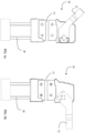
- FIG. 1a a preferred embodiment of an actuating unit with articulated lever or cam according to the present invention, indicated as a whole with 10, specifically made in the form of a clamping unit is illustrated.
- the clamping unit 10 comprises a housing body 11 within which a locking device of the articulated lever or cam type (not shown) is arranged, switchable between a first configuration, in which an actuating arm 12 is brought into an angular open position, illustrated in fig. 1a , and a second configuration, in which the actuating arm 12 is brought into an angular closed position, illustrated in fig. 1b .
- the locking device is actuated by means of a pneumatic actuator 20 comprising a cylindrical body 21 having a centre-line axis C extending between a pair of heads 22,23 of which a first one 22 located at a free end of the cylinder 21 and incorporating at least one connection mouth 31 to a pressurized fluid supply, and a second one 23 acting as a connection interface with the housing body 11 of the locking device.
- a pneumatic actuator 20 comprising a cylindrical body 21 having a centre-line axis C extending between a pair of heads 22,23 of which a first one 22 located at a free end of the cylinder 21 and incorporating at least one connection mouth 31 to a pressurized fluid supply, and a second one 23 acting as a connection interface with the housing body 11 of the locking device.
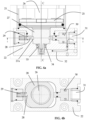
- a piston provided with a base 25 sealingly coupled to the inner wall of the body 21, a control rod 26 extending from the base 25 along the axis C towards the interface head 23 and a first retaining element 27 extending from the base 25 towards the free head 22 are translatably housed inside the cylindrical body 21.
- the first retaining element 27 preferably has a tapered shape in the direction towards the free end 22.
- a shock-absorbing cone 33 intended to be accommodated in a seal 34 housed in the free head 22 is included on the first retaining element 27.
- An abutting projection 27a configured to engage a second retaining element 28 is provided in the first retaining element 27 so as to prevent the translation of the piston away from the free head 22.
- the second retaining element 28 is housed in the free head 22 translatably in a plane transverse to the axis C between a position of engagement with the abutting projection 27a (illustrated in figure 3a ) and a position of disengagement from the abutting projection 27a (illustrated in figure 4a ).
- the abutting projection 27a is a wall of a seat made in the first retaining element, within which the second retaining element 28 is received when in its engaged position. More in detail, in the illustrated embodiment, the abutting projection 27a is a wall of a receiving seat of a second retaining element 28 extending along at least a surface portion of the first retaining element 27, preferably extending around the first retaining element 27.
- the second retaining element 28 is forced into the engaged position against the abutting projection 27a by an elastic return element 29 acting in the translation plane of the second retaining element 28.
- the second retaining element 28 is further acted upon, in opposition to the elastic return element 29, by a release pusher 30 housed at a supply mouth 31 of a pressurized fluid.
- the release pusher 30 is housed in the supply mouth 31 so as to be translatable in the translation plane of the second retaining element 28 under the action exerted by the pressurized fluid, exerting on the second retaining element 28 a force counteracting the elastic force exerted by the elastic return element 29.
- the second retaining element 28 can be pushed by the release pusher 30 into the disengagement position from the projection 27a (illustrated in figure 4a ).
- the release pusher 30 is advantageously housed in the supply mouth 31 so that it is free to translate between a rest position in which the pusher 30 is more distanced from the elastic return element 29, allowing the latter to keep the second retaining element 28 in the engaged position, and a compression position, in which the pusher 30 pushes the second retaining element 28 to approach the elastic return element 29 by the compression of the latter.
- the pusher 30 obstructs a supply pipe 32 of the pressurized fluid to the piston 25,26,27, while in the compression position (illustrated in figure 4a ), the pusher 30 does not obstruct the supply pipe 32, allowing the pressurized fluid to reach the piston.
- the second retaining element 28 is advantageously obtained in the form of a perforated plate in which the hole has a sufficient diameter to accommodate the first retaining element 27 with clearance.
- the second retaining element 28 can assume different conformations, for example by having a housing for the first retaining element 27 which is not necessarily closed.
- the pneumatic actuator 20 is not energized and therefore the release pusher 30 is not forced by the pressurized fluid to counteract the force exerted by the elastic return element 29, thus being in the position distanced from said element 29.
- This allows the elastic return element 29 to force the second retaining element 28 into the engaged position against the abutting projection 27a.
- the piston is locked in its position against the free end 22, ensuring that it maintains such a position even when subjected to axial stress. This ensures that the actuating arm 12 is reliably maintained in its open position (illustrated in figure 1a ).
- the pressurized fluid initially acts on the release pusher 30 because, in the initial configuration, the supply pipe 32 of the pressurized fluid to the piston 25,26,27 is obstructed by the pusher 30 itself.
- the pressurized fluid exerts a thrust force sufficient to counteract the force exerted by the elastic return element 29, allowing the release pusher 30 and the second retaining element 28 to translate.
- the release pusher 30 acts on the second retaining element 28, overcoming the force exerted by the elastic return element 29 and pushing the second retaining element 28 towards its disengagement position from the projection 27a (illustrated in figures 4a and 4b ). Thereby the piston is free to move.
- the movement of the release pusher 30 also causes the opening of the supply pipe 32 and thus a gradual increase in the pressure exerted on the piston until it moves.
- the release pusher 30 In the absence of a pressurized fluid supply, the release pusher 30 returns to its distanced position from the spring return element 29, allowing said spring return element 29 to push the second retaining element 28 towards the engagement position (see figure 2a ).
Landscapes
- Engineering & Computer Science (AREA)
- Mechanical Engineering (AREA)
- Physics & Mathematics (AREA)
- Fluid Mechanics (AREA)
- General Engineering & Computer Science (AREA)
- Actuator (AREA)
- Accommodation For Nursing Or Treatment Tables (AREA)
- Coupling Device And Connection With Printed Circuit (AREA)
Claims (12)
- Betätigungseinheit (10) vom Gelenkhebel- oder Nockentyp, umfassend:- einen zwischen einer offenen Position und einer geschlossenen Betriebsposition drehbaren Betätigungsarm (12);- einen Gehäusekörper (11), in dessen Inneren eine Schließvorrichtung aufgenommen ist, welche dazu eingerichtet ist, den Betätigungsarm (12) zwischen der offenen Position und der geschlossenen Betriebsposition in Drehung zu versetzen, wobei die Schließvorrichtung einen Bewegungs-Unumkehrbarkeitsmechanismus aufweist, welcher, beim Erreichen der geschlossenen Betriebsposition durch den Betätigungsarm (12), dazu eingerichtet ist, ausgelöst zu werden;
und- einen fluiddynamischen Aktuator (20), welcher dazu eingerichtet ist, die Bewegung der Schließvorrichtung zu steuern, der fluiddynamische Aktuator (20) umfassend einen zylindrischen Körper (21), welcher sich zwischen einem an einem freien Ende des zylindrischen Körpers (21) angeordneten ersten freien Kopf (22) und einem zweiten Kopf (23) zur Verbindung mit dem Gehäusekörper (11) erstreckt; und einen im Inneren des zylindrischen Körpers (21) verschiebbar aufgenommenen Kolben,wobei der Kolben ein erstes Halteelement (27) trägt, welches dazu eingerichtet ist, mit einem zweiten Halteelement (28) in Eingriff zu kommen, welches im Inneren des freien Kopfes (22) aufgenommen ist, wobei das zweite Halteelement (28) zwischen einer Eingriffsposition und einer Freigabeposition von dem ersten Halteelement (27) beweglich ist,dadurch gekennzeichnet, dass es ein Schubelement (30) umfasst, welches dazu eingerichtet ist, das zweite Halteelement (28) in die Freigabeposition von dem ersten Halteelement (27) zu versetzen, wobei das Schubelement (30) in dem fluiddynamischen Aktuator (20) derart eingerichtet und/oder aufgenommen ist, um mittels eines unter Druck stehenden Fluids betätigbar zu werden, und und in dem freien Kopf (22) aufgenommen ist, um einen Fluidfluss zwischen einer Druckfluid-Zuführungsmündung (31) und einer inneren Kammer des zylindrischen Körpers (21), in dem der Kolben aufgenommen ist, abzufangen, wobei das Schubelement (30) zwischen einer Ruheposition, in welcher es den Durchfluss von Druckfluid zu der inneren Kammer des zylindrischen Körpers (21) behindert, und einer Schubposition, in welcher es den Durchfluss von Druckfluid zu der inneren Kammer des zylindrischen Körpers (21) freigibt, bewegbar ist. - Betätigungseinheit (10) nach Anspruch 1, wobei das Schubelement (30) in dem freien Kopf (22) an der Druckmittel-Zuführungsmündung (31) aufgenommen ist.
- Betätigungseinheit (10) nach Anspruch 2, wobei der freie Kopf (22) eine Druckfluid-Zuführungsleitung (32) aufweist, welche die Zuführungsmündung (31) mit der Innenkammer des zylindrischen Körpers (21) verbindet, wobei der Einlass der Zuführungsleitung (32) durch das Schubelement (30) blockiert ist, wenn dieses sich in der Ruheposition befindet, und durch das Schubelement (30) freigegeben wird, wenn dieses sich in der Schubposition befindet.
- Betätigungseinheit (10) nach einem der vorhergehenden Ansprüche, wobei das zweite Halteelement (28) ein plattenförmiges Lochelement ist, in welchem das Loch Abmessungen aufweist, um das erste Halteelement (27) mit Spiel aufzunehmen.
- Betätigungseinheit (10) nach einem der vorhergehenden Ansprüche, wobei das erste Halteelement (27) in Richtung des freien Kopfes (22) verjüngt ist, um das Erreichen einer Eingriffskonfiguration mit dem zweiten Halteelement (28) zu erleichtern.
- Betätigungseinheit (10) nach einem der vorhergehenden Ansprüche, wobei ein Anschlagvorsprung (27a) in dem ersten Halteelement (27) erhalten wird, welcher dazu eingerichtet ist, mit dem zweiten Halteelement (28) in Eingriff zu kommen, um das Verschieben des Kolbens weg von dem freien Kopf (22) zu verhindern.
- Betätigungseinheit (10) nach Anspruch 6, wobei der Anschlagvorsprung (27a) eine Wand ist, welche zumindest teilweise einen in dem ersten Halteelement (27) erhaltenen Sitz begrenzt, wobei der Sitz dazu eingerichtet ist, das zweite Halteelement (28) darin aufzunehmen, wenn es sich in seiner Eingriffsposition befindet, wobei sich der Sitz vorzugsweise entlang zumindest eines Oberflächenabschnitts des ersten Halteelements (27) erstreckt, besonders vorzugsweise um das erste Halteelement (27) herum erstreckt.
- Betätigungseinheit (10) nach einem der vorhergehenden Ansprüche, wobei der Kolben eine Basis (25), welche abdichtend mit einer Innenwand des zylindrischen Körpers (21) gekoppelt ist, und eine Steuerstange (26) umfasst, welche sich von der Basis (25) entlang einer Achse (C) des zylindrischen Körpers (21) in Richtung des Verbindungskopfes (23) erstreckt, wobei sich das von dem Kolben getragene erste Halteelement (27) von der Basis (25) in Richtung des freien Kopfes (22) erstreckt.
- Betätigungseinheit (10) nach einem der vorhergehenden Ansprüche, wobei das erste Halteelement (27) einen Stoßdämpferkonus (33) trägt, welcher dazu eingerichtet ist, in einer in dem freien Kopf (22) aufgenommenen Dichtung (34) aufgenommen zu werden.
- Betätigungseinheit (10) nach einem der vorhergehenden Ansprüche, wobei das zweite Halteelement (28) in dem freien Kopf (22) verschiebbar in einer Ebene quer zur Achse (C) des zylindrischen Körpers (21) zwischen der Eingriffsposition und der Freigabeposition von dem ersten Halteelement (27) aufgenommen ist.
- Betätigungseinheit (10) nach Anspruch 10, wobei das Schubelement (30) dazu eingerichtet ist, in der Verschiebungsebene des zweiten Halteelements (28) unter der Wirkung des unter Druck stehenden Fluids verschiebbar zu sein.
- Betätigungseinheit (10) nach einem der vorhergehenden Ansprüche, umfassend ein elastisches Rückstellelement (29), welches dazu eingerichtet ist, das zweite Halteelement (28) in die Eingriffsposition mit dem ersten Halteelement (27) zu bringen, wobei vorzugsweise das Schubelement (30) dazu eingerichtet ist, eine Gegenkraft zu der von dem elastischen Rückstellelement (29) ausgeübten elastischen Kraft auszuüben.
Applications Claiming Priority (1)
| Application Number | Priority Date | Filing Date | Title |
|---|---|---|---|
| IT102021000007511A IT202100007511A1 (it) | 2021-03-26 | 2021-03-26 | Unita’ di attuazione del tipo a leva articolata o a camma con gruppo di auto-ritenuta integrato |
Publications (2)
| Publication Number | Publication Date |
|---|---|
| EP4063071A1 EP4063071A1 (de) | 2022-09-28 |
| EP4063071B1 true EP4063071B1 (de) | 2025-04-30 |
Family
ID=76269978
Family Applications (1)
| Application Number | Title | Priority Date | Filing Date |
|---|---|---|---|
| EP22163299.5A Active EP4063071B1 (de) | 2021-03-26 | 2022-03-21 | Betätigungseinheit |
Country Status (2)
| Country | Link |
|---|---|
| EP (1) | EP4063071B1 (de) |
| IT (1) | IT202100007511A1 (de) |
Families Citing this family (1)
| Publication number | Priority date | Publication date | Assignee | Title |
|---|---|---|---|---|
| IT202300019569A1 (it) * | 2023-09-22 | 2025-03-22 | Fmt S R L | Dispositivo per la regolazione e/o bloccaggio semplificato |
Family Cites Families (9)
| Publication number | Priority date | Publication date | Assignee | Title |
|---|---|---|---|---|
| US3889576A (en) | 1969-06-13 | 1975-06-17 | Sheffer Corp | Locking cylinder with improved locking structure |
| US4784037A (en) * | 1982-12-28 | 1988-11-15 | The United States Of America As Represented By The United States Department Of Energy | Locking apparatus for gate valves |
| US4524676A (en) * | 1984-01-19 | 1985-06-25 | American Standard Inc. | Hydraulic cylinder locking device |
| DE29817335U1 (de) | 1998-09-26 | 1999-02-18 | Tünkers Maschinenbau GmbH, 40880 Ratingen | Spannvorrichtung, insbesondere Kniehebelspannvorrichtung, vornehmlich zur Verwendung im Karosseriebau der Kfz-Industrie |
| DE29920639U1 (de) | 1999-11-24 | 2000-03-30 | Tünkers Maschinenbau GmbH, 40880 Ratingen | Kniehebelspannvorrichtung, insbesondere zur Verwendung im Karosseriebau der Kfz-Industrie |
| TW487617B (en) | 2000-08-04 | 2002-05-21 | Smc Kk | Clamp apparatus |
| DE102004059201A1 (de) * | 2004-12-09 | 2006-06-22 | Bosch Rexroth Teknik Ab | Linearzylindereinheit |
| DE202004019495U1 (de) | 2004-12-17 | 2005-03-10 | Tünkers Maschinenbau Gmbh | Durch Druckmitteldruck, insbesondere pneuamtisch, betätigte Kolben-Zylinder-Einheit, bei welcher ein mit einer Kolbenstange verbundener Kolben durch Druckmittelbeaufschlagung linear bewegbar ist, z.B. druckmittelbetätigbare Kniehebelspannvorrichtung, insbesondere für den Karosseriebau der Kfz-Industrie |
| JP4406886B2 (ja) * | 2005-07-07 | 2010-02-03 | Smc株式会社 | 流体圧機器に用いられるロック機構 |
-
2021
- 2021-03-26 IT IT102021000007511A patent/IT202100007511A1/it unknown
-
2022
- 2022-03-21 EP EP22163299.5A patent/EP4063071B1/de active Active
Also Published As
| Publication number | Publication date |
|---|---|
| IT202100007511A1 (it) | 2022-09-26 |
| EP4063071A1 (de) | 2022-09-28 |
Similar Documents
| Publication | Publication Date | Title |
|---|---|---|
| EP2152987B1 (de) | Notöffnungsmechanismus für türen | |
| US5735557A (en) | Lock mechanism | |
| KR102105220B1 (ko) | 블로 다운 액추에이터 조립체 | |
| EP4063071B1 (de) | Betätigungseinheit | |
| US11067209B2 (en) | Connection adapter, in particular for air-conditioning systems | |
| EP3134659B1 (de) | Fluidbetätigte über-die-mitte-kupplung für einen abtrieb | |
| US6832539B2 (en) | Cylinder lock | |
| US6450082B1 (en) | Shot pin | |
| US12117127B2 (en) | Packaging device, assembly comprising such a device and a container, use thereof and a method for filling or withdrawing | |
| EP3613999B1 (de) | Äusserlich verifizierbare thermische kompensation eines haubenöffnungsaktuators | |
| EP3452239B1 (de) | Pneumatisches nietgerät mit einem hebel und einer entriegelungsanordnung zur verhinderung oder ermöglichung der bedienung des hebels | |
| CN109803794A (zh) | 具有单次和接触触发的气动钉枪 | |
| US5178360A (en) | Wire cutting valve actuator | |
| EP0692640A2 (de) | Druckmittelbetätigte Vorrichtung zum Öffnen und Schliessen ein Dachfensters oder einer Luke | |
| EP3611414B1 (de) | Auslösungsmechanismus für eine ventilanordnung | |
| EP4034337B1 (de) | Betätigungseinheit vom gelenkhebel- oder nockentyp mit einer bremseinheit | |
| EP4276298B1 (de) | Betätigungssysteme für schubumkehrvorrichtung | |
| EP1120596B1 (de) | Notauslösbare Kupplung infolge eines hohen axialen Zuges | |
| JPH04231138A (ja) | リベット固定工具 | |
| JP4445935B2 (ja) | 緊急遮断弁 | |
| GB2404696A (en) | Actuator with integral lock |
Legal Events
| Date | Code | Title | Description |
|---|---|---|---|
| PUAI | Public reference made under article 153(3) epc to a published international application that has entered the european phase |
Free format text: ORIGINAL CODE: 0009012 |
|
| STAA | Information on the status of an ep patent application or granted ep patent |
Free format text: STATUS: THE APPLICATION HAS BEEN PUBLISHED |
|
| AK | Designated contracting states |
Kind code of ref document: A1 Designated state(s): AL AT BE BG CH CY CZ DE DK EE ES FI FR GB GR HR HU IE IS IT LI LT LU LV MC MK MT NL NO PL PT RO RS SE SI SK SM TR |
|
| STAA | Information on the status of an ep patent application or granted ep patent |
Free format text: STATUS: REQUEST FOR EXAMINATION WAS MADE |
|
| 17P | Request for examination filed |
Effective date: 20230327 |
|
| RBV | Designated contracting states (corrected) |
Designated state(s): AL AT BE BG CH CY CZ DE DK EE ES FI FR GB GR HR HU IE IS IT LI LT LU LV MC MK MT NL NO PL PT RO RS SE SI SK SM TR |
|
| P01 | Opt-out of the competence of the unified patent court (upc) registered |
Effective date: 20230329 |
|
| GRAP | Despatch of communication of intention to grant a patent |
Free format text: ORIGINAL CODE: EPIDOSNIGR1 |
|
| STAA | Information on the status of an ep patent application or granted ep patent |
Free format text: STATUS: GRANT OF PATENT IS INTENDED |
|
| INTG | Intention to grant announced |
Effective date: 20241108 |
|
| GRAS | Grant fee paid |
Free format text: ORIGINAL CODE: EPIDOSNIGR3 |
|
| GRAA | (expected) grant |
Free format text: ORIGINAL CODE: 0009210 |
|
| STAA | Information on the status of an ep patent application or granted ep patent |
Free format text: STATUS: THE PATENT HAS BEEN GRANTED |
|
| AK | Designated contracting states |
Kind code of ref document: B1 Designated state(s): AL AT BE BG CH CY CZ DE DK EE ES FI FR GB GR HR HU IE IS IT LI LT LU LV MC MK MT NL NO PL PT RO RS SE SI SK SM TR |
|
| REG | Reference to a national code |
Ref country code: CH Ref legal event code: EP Ref country code: GB Ref legal event code: FG4D |
|
| REG | Reference to a national code |
Ref country code: DE Ref legal event code: R096 Ref document number: 602022013751 Country of ref document: DE |
|
| REG | Reference to a national code |
Ref country code: IE Ref legal event code: FG4D |
|
| REG | Reference to a national code |
Ref country code: NL Ref legal event code: MP Effective date: 20250430 |
|
| REG | Reference to a national code |
Ref country code: AT Ref legal event code: MK05 Ref document number: 1789611 Country of ref document: AT Kind code of ref document: T Effective date: 20250430 |
|
| PG25 | Lapsed in a contracting state [announced via postgrant information from national office to epo] |
Ref country code: FI Free format text: LAPSE BECAUSE OF FAILURE TO SUBMIT A TRANSLATION OF THE DESCRIPTION OR TO PAY THE FEE WITHIN THE PRESCRIBED TIME-LIMIT Effective date: 20250430 Ref country code: PT Free format text: LAPSE BECAUSE OF FAILURE TO SUBMIT A TRANSLATION OF THE DESCRIPTION OR TO PAY THE FEE WITHIN THE PRESCRIBED TIME-LIMIT Effective date: 20250901 Ref country code: ES Free format text: LAPSE BECAUSE OF FAILURE TO SUBMIT A TRANSLATION OF THE DESCRIPTION OR TO PAY THE FEE WITHIN THE PRESCRIBED TIME-LIMIT Effective date: 20250430 |
|
| REG | Reference to a national code |
Ref country code: LT Ref legal event code: MG9D |
|
| PG25 | Lapsed in a contracting state [announced via postgrant information from national office to epo] |
Ref country code: NO Free format text: LAPSE BECAUSE OF FAILURE TO SUBMIT A TRANSLATION OF THE DESCRIPTION OR TO PAY THE FEE WITHIN THE PRESCRIBED TIME-LIMIT Effective date: 20250730 Ref country code: GR Free format text: LAPSE BECAUSE OF FAILURE TO SUBMIT A TRANSLATION OF THE DESCRIPTION OR TO PAY THE FEE WITHIN THE PRESCRIBED TIME-LIMIT Effective date: 20250731 |
|
| PG25 | Lapsed in a contracting state [announced via postgrant information from national office to epo] |
Ref country code: NL Free format text: LAPSE BECAUSE OF FAILURE TO SUBMIT A TRANSLATION OF THE DESCRIPTION OR TO PAY THE FEE WITHIN THE PRESCRIBED TIME-LIMIT Effective date: 20250430 Ref country code: PL Free format text: LAPSE BECAUSE OF FAILURE TO SUBMIT A TRANSLATION OF THE DESCRIPTION OR TO PAY THE FEE WITHIN THE PRESCRIBED TIME-LIMIT Effective date: 20250430 |
|
| PG25 | Lapsed in a contracting state [announced via postgrant information from national office to epo] |
Ref country code: BG Free format text: LAPSE BECAUSE OF FAILURE TO SUBMIT A TRANSLATION OF THE DESCRIPTION OR TO PAY THE FEE WITHIN THE PRESCRIBED TIME-LIMIT Effective date: 20250430 |
|
| PG25 | Lapsed in a contracting state [announced via postgrant information from national office to epo] |
Ref country code: HR Free format text: LAPSE BECAUSE OF FAILURE TO SUBMIT A TRANSLATION OF THE DESCRIPTION OR TO PAY THE FEE WITHIN THE PRESCRIBED TIME-LIMIT Effective date: 20250430 |
|
| PG25 | Lapsed in a contracting state [announced via postgrant information from national office to epo] |
Ref country code: AT Free format text: LAPSE BECAUSE OF FAILURE TO SUBMIT A TRANSLATION OF THE DESCRIPTION OR TO PAY THE FEE WITHIN THE PRESCRIBED TIME-LIMIT Effective date: 20250430 |
|
| PG25 | Lapsed in a contracting state [announced via postgrant information from national office to epo] |
Ref country code: RS Free format text: LAPSE BECAUSE OF FAILURE TO SUBMIT A TRANSLATION OF THE DESCRIPTION OR TO PAY THE FEE WITHIN THE PRESCRIBED TIME-LIMIT Effective date: 20250731 |
|
| PG25 | Lapsed in a contracting state [announced via postgrant information from national office to epo] |
Ref country code: IS Free format text: LAPSE BECAUSE OF FAILURE TO SUBMIT A TRANSLATION OF THE DESCRIPTION OR TO PAY THE FEE WITHIN THE PRESCRIBED TIME-LIMIT Effective date: 20250830 |
|
| PG25 | Lapsed in a contracting state [announced via postgrant information from national office to epo] |
Ref country code: LV Free format text: LAPSE BECAUSE OF FAILURE TO SUBMIT A TRANSLATION OF THE DESCRIPTION OR TO PAY THE FEE WITHIN THE PRESCRIBED TIME-LIMIT Effective date: 20250430 |
|
| PG25 | Lapsed in a contracting state [announced via postgrant information from national office to epo] |
Ref country code: DK Free format text: LAPSE BECAUSE OF FAILURE TO SUBMIT A TRANSLATION OF THE DESCRIPTION OR TO PAY THE FEE WITHIN THE PRESCRIBED TIME-LIMIT Effective date: 20250430 Ref country code: SM Free format text: LAPSE BECAUSE OF FAILURE TO SUBMIT A TRANSLATION OF THE DESCRIPTION OR TO PAY THE FEE WITHIN THE PRESCRIBED TIME-LIMIT Effective date: 20250430 |
|
| PG25 | Lapsed in a contracting state [announced via postgrant information from national office to epo] |
Ref country code: CZ Free format text: LAPSE BECAUSE OF FAILURE TO SUBMIT A TRANSLATION OF THE DESCRIPTION OR TO PAY THE FEE WITHIN THE PRESCRIBED TIME-LIMIT Effective date: 20250430 |
|
| PG25 | Lapsed in a contracting state [announced via postgrant information from national office to epo] |
Ref country code: EE Free format text: LAPSE BECAUSE OF FAILURE TO SUBMIT A TRANSLATION OF THE DESCRIPTION OR TO PAY THE FEE WITHIN THE PRESCRIBED TIME-LIMIT Effective date: 20250430 |
|
| PG25 | Lapsed in a contracting state [announced via postgrant information from national office to epo] |
Ref country code: SK Free format text: LAPSE BECAUSE OF FAILURE TO SUBMIT A TRANSLATION OF THE DESCRIPTION OR TO PAY THE FEE WITHIN THE PRESCRIBED TIME-LIMIT Effective date: 20250430 |
|
| PG25 | Lapsed in a contracting state [announced via postgrant information from national office to epo] |
Ref country code: IT Free format text: LAPSE BECAUSE OF FAILURE TO SUBMIT A TRANSLATION OF THE DESCRIPTION OR TO PAY THE FEE WITHIN THE PRESCRIBED TIME-LIMIT Effective date: 20250430 |
|
| REG | Reference to a national code |
Ref country code: DE Ref legal event code: R097 Ref document number: 602022013751 Country of ref document: DE |
|
| PLBE | No opposition filed within time limit |
Free format text: ORIGINAL CODE: 0009261 |
|
| STAA | Information on the status of an ep patent application or granted ep patent |
Free format text: STATUS: NO OPPOSITION FILED WITHIN TIME LIMIT |
|
| REG | Reference to a national code |
Ref country code: CH Ref legal event code: L10 Free format text: ST27 STATUS EVENT CODE: U-0-0-L10-L00 (AS PROVIDED BY THE NATIONAL OFFICE) Effective date: 20260311 |
|
| 26N | No opposition filed |
Effective date: 20260202 |