EP4060880B1 - Verfahren und vorrichtung zur justierung eines permanentmagnetmotors sowie vorrichtung und speichermedium - Google Patents
Verfahren und vorrichtung zur justierung eines permanentmagnetmotors sowie vorrichtung und speichermedium Download PDFInfo
- Publication number
- EP4060880B1 EP4060880B1 EP20924123.1A EP20924123A EP4060880B1 EP 4060880 B1 EP4060880 B1 EP 4060880B1 EP 20924123 A EP20924123 A EP 20924123A EP 4060880 B1 EP4060880 B1 EP 4060880B1
- Authority
- EP
- European Patent Office
- Prior art keywords
- permanent magnet
- magnet motor
- parameter
- adjusted
- short
- Prior art date
- Legal status (The legal status is an assumption and is not a legal conclusion. Google has not performed a legal analysis and makes no representation as to the accuracy of the status listed.)
- Active
Links
Images


Classifications
-
- H—ELECTRICITY
- H02—GENERATION; CONVERSION OR DISTRIBUTION OF ELECTRIC POWER
- H02K—DYNAMO-ELECTRIC MACHINES
- H02K15/00—Processes or apparatus specially adapted for manufacturing, assembling, maintaining or repairing of dynamo-electric machines
-
- H—ELECTRICITY
- H02—GENERATION; CONVERSION OR DISTRIBUTION OF ELECTRIC POWER
- H02K—DYNAMO-ELECTRIC MACHINES
- H02K15/00—Processes or apparatus specially adapted for manufacturing, assembling, maintaining or repairing of dynamo-electric machines
- H02K15/02—Processes or apparatus specially adapted for manufacturing, assembling, maintaining or repairing of dynamo-electric machines of stator or rotor bodies
- H02K15/03—Processes or apparatus specially adapted for manufacturing, assembling, maintaining or repairing of dynamo-electric machines of stator or rotor bodies having permanent magnets
-
- H—ELECTRICITY
- H02—GENERATION; CONVERSION OR DISTRIBUTION OF ELECTRIC POWER
- H02P—CONTROL OR REGULATION OF ELECTRIC MOTORS, ELECTRIC GENERATORS OR DYNAMO-ELECTRIC CONVERTERS; CONTROLLING TRANSFORMERS, REACTORS OR CHOKE COILS
- H02P6/00—Arrangements for controlling synchronous motors or other dynamo-electric motors using electronic commutation dependent on the rotor position; Electronic commutators therefor
- H02P6/14—Electronic commutators
- H02P6/16—Circuit arrangements for detecting position
- H02P6/18—Circuit arrangements for detecting position without separate position detecting elements
- H02P6/182—Circuit arrangements for detecting position without separate position detecting elements using back-emf in windings
-
- H—ELECTRICITY
- H02—GENERATION; CONVERSION OR DISTRIBUTION OF ELECTRIC POWER
- H02K—DYNAMO-ELECTRIC MACHINES
- H02K11/00—Structural association of dynamo-electric machines with electric components or with devices for shielding, monitoring or protection
- H02K11/20—Structural association of dynamo-electric machines with electric components or with devices for shielding, monitoring or protection for measuring, monitoring, testing, protecting or switching
- H02K11/26—Devices for sensing voltage, or actuated thereby, e.g. overvoltage protection devices
-
- H—ELECTRICITY
- H02—GENERATION; CONVERSION OR DISTRIBUTION OF ELECTRIC POWER
- H02K—DYNAMO-ELECTRIC MACHINES
- H02K15/00—Processes or apparatus specially adapted for manufacturing, assembling, maintaining or repairing of dynamo-electric machines
- H02K15/50—Disassembling, repairing or modifying dynamo-electric machines
-
- H—ELECTRICITY
- H02—GENERATION; CONVERSION OR DISTRIBUTION OF ELECTRIC POWER
- H02P—CONTROL OR REGULATION OF ELECTRIC MOTORS, ELECTRIC GENERATORS OR DYNAMO-ELECTRIC CONVERTERS; CONTROLLING TRANSFORMERS, REACTORS OR CHOKE COILS
- H02P23/00—Arrangements or methods for the control of AC motors characterised by a control method other than vector control
- H02P23/0004—Control strategies in general, e.g. linear type, e.g. P, PI, PID, using robust control
-
- H—ELECTRICITY
- H02—GENERATION; CONVERSION OR DISTRIBUTION OF ELECTRIC POWER
- H02P—CONTROL OR REGULATION OF ELECTRIC MOTORS, ELECTRIC GENERATORS OR DYNAMO-ELECTRIC CONVERTERS; CONTROLLING TRANSFORMERS, REACTORS OR CHOKE COILS
- H02P29/00—Arrangements for regulating or controlling electric motors, appropriate for both AC and DC motors
- H02P29/02—Providing protection against overload without automatic interruption of supply
- H02P29/024—Detecting a fault condition, e.g. short circuit, locked rotor, open circuit or loss of load
- H02P29/027—Detecting a fault condition, e.g. short circuit, locked rotor, open circuit or loss of load the fault being an over-current
-
- H—ELECTRICITY
- H02—GENERATION; CONVERSION OR DISTRIBUTION OF ELECTRIC POWER
- H02P—CONTROL OR REGULATION OF ELECTRIC MOTORS, ELECTRIC GENERATORS OR DYNAMO-ELECTRIC CONVERTERS; CONTROLLING TRANSFORMERS, REACTORS OR CHOKE COILS
- H02P29/00—Arrangements for regulating or controlling electric motors, appropriate for both AC and DC motors
- H02P29/02—Providing protection against overload without automatic interruption of supply
- H02P29/024—Detecting a fault condition, e.g. short circuit, locked rotor, open circuit or loss of load
- H02P29/028—Detecting a fault condition, e.g. short circuit, locked rotor, open circuit or loss of load the motor continuing operation despite the fault condition, e.g. eliminating, compensating for or remedying the fault
-
- H—ELECTRICITY
- H02—GENERATION; CONVERSION OR DISTRIBUTION OF ELECTRIC POWER
- H02P—CONTROL OR REGULATION OF ELECTRIC MOTORS, ELECTRIC GENERATORS OR DYNAMO-ELECTRIC CONVERTERS; CONTROLLING TRANSFORMERS, REACTORS OR CHOKE COILS
- H02P29/00—Arrangements for regulating or controlling electric motors, appropriate for both AC and DC motors
- H02P29/02—Providing protection against overload without automatic interruption of supply
- H02P29/032—Preventing damage to the motor, e.g. setting individual current limits for different drive conditions
-
- H—ELECTRICITY
- H02—GENERATION; CONVERSION OR DISTRIBUTION OF ELECTRIC POWER
- H02P—CONTROL OR REGULATION OF ELECTRIC MOTORS, ELECTRIC GENERATORS OR DYNAMO-ELECTRIC CONVERTERS; CONTROLLING TRANSFORMERS, REACTORS OR CHOKE COILS
- H02P29/00—Arrangements for regulating or controlling electric motors, appropriate for both AC and DC motors
- H02P29/60—Controlling or determining the temperature of the motor or of the drive
- H02P29/67—Controlling or determining the motor temperature by back electromotive force [back-EMF] evaluation
-
- H—ELECTRICITY
- H02—GENERATION; CONVERSION OR DISTRIBUTION OF ELECTRIC POWER
- H02K—DYNAMO-ELECTRIC MACHINES
- H02K2213/00—Specific aspects, not otherwise provided for and not covered by codes H02K2201/00 - H02K2211/00
- H02K2213/06—Machines characterised by the presence of fail safe, back up, redundant or other similar emergency arrangements
-
- H—ELECTRICITY
- H02—GENERATION; CONVERSION OR DISTRIBUTION OF ELECTRIC POWER
- H02P—CONTROL OR REGULATION OF ELECTRIC MOTORS, ELECTRIC GENERATORS OR DYNAMO-ELECTRIC CONVERTERS; CONTROLLING TRANSFORMERS, REACTORS OR CHOKE COILS
- H02P2207/00—Indexing scheme relating to controlling arrangements characterised by the type of motor
- H02P2207/05—Synchronous machines, e.g. with permanent magnets or DC excitation
Definitions
- the disclosure relates to a rail transit technology, and particularly to a method and device for adjusting a permanent magnet motor, an equipment, and a storage medium.
- a rail transit vehicle has become an important means of transportation in the modern society.
- a motor may be arranged in the rail transit vehicle, and the motor is an important device for ensuring the normal operation of the rail transit vehicle.
- the motor refers to an electromagnetic device converting or transmitting electric energy according to the law of electromagnetic induction.
- a rotating magnetic field is formed in a stator winding after a three-phase current is input to the stator winding. Since a permanent magnet with fixed magnetic poles is mounted on a rotor, the rotating magnetic field generated in a stator may drive the rotor to rotate according to the principle that like poles repel and unlike poles attract.
- a magnetic field of a permanent magnet rotor performs a cutting motion on a coil wire to generate a counter electromotive force (CEMF) in the coil wire, when the rotor rotates.
- CEMF counter electromotive force
- the disclosure provides a method and device for adjusting a permanent magnet motor, an equipment, and a storage medium, to solve the problem of how to ensure the operational safety of a motor of a rail transit vehicle in case of an inter-turn short circuit of a coil of the motor.
- the disclosure provides a method for adjusting a permanent magnet motor, which may include the following operations.
- a CEMF parameter information of an electromagnetic structure of a permanent magnet motor to be adjusted and a minimum impedance value of any short-circuited coil of the permanent magnet motor to be adjusted are acquired, here the CEMF parameter is a CEMF value of the permanent magnet motor at a maximum rotational speed.
- An operational time of a smallest short-circuited coil is determined according to the CEMF parameter, the information of the electromagnetic structure and the minimum impedance value.
- An adjustment instruction configured to instruct an production equipment to adjust the electromagnetic structure of the permanent magnet motor to be adjusted is transmitted to the production equipment when the operational time is inconsistent with a preset time, so that the production equipment adjusts the electromagnetic structure of the permanent magnet motor to be adjusted.
- the operation that the CEMF parameter is acquired may include the following operations.
- An acquisition instruction is transmitted to a test permanent magnet motor, and the CEMF parameter returned by the test permanent magnet motor according to the acquisition instruction is received.
- the CEMF value of the permanent magnet motor at the maximum rotational speed is determined through a simulation technology.
- the operation that the operational time of the short-circuited coil is determined according to the CEMF parameter, the information of the electromagnetic structure and the minimum impedance value may include the following operations.
- a generated heat value of the short-circuited coil is determined according to the CEMF parameter and the minimum impedance value.
- the operational time of the short-circuited coil is determined according to the generated heat value of the short-circuited coil and the information of the electromagnetic structure.
- the method may further include the following operations.
- a coil parameter of a coil of the permanent magnet motor to be adjusted is acquired.
- the operation that the generated heat value of the short-circuited coil is determined according to the CEMF parameter and the minimum impedance value may include the following operations.
- a current density of the short-circuited coil is determined according to the coil parameter and the current value.
- the generated heat value of the short-circuited coil is determined according to the current density and the minimum impedance value.
- the information of the electromagnetic structure of the permanent magnet motor to be adjusted may include one or more of: information of a cooling structure of the motor, a melting point of an insulating material, a permanent magnet parameter, a slot shape parameter of the motor, or an electromagnetic wire parameter.
- the adjustment instruction may specifically be configured to instruct the production equipment to perform one or more of: adjusting the permanent magnet parameter, replacing the insulating material, adjusting a cooling structure of the permanent magnet motor, adjusting the slot shape parameter of the motor, or adjusting the electromagnetic wire parameter, on the permanent magnet motor to be adjusted.
- the method may further include the following operations.
- a target rotational speed of the permanent magnet motor to be adjusted is determined according to the information of the electromagnetic structure, the minimum impedance value, and a target operational time of the permanent magnet motor.
- a parameter to be adjusted is determined according to the target rotational speed.
- An operational speed of the permanent magnet motor to be adjusted is adjusted according to the parameter to be adjusted.
- the disclosure provides a device for adjusting a permanent magnet motor, which may include a first acquisition unit, a first processing unit, a judgment unit, and a first adjustment unit.
- the first acquisition unit may be configured to acquire a CEMF parameter, information of an electromagnetic structure of a permanent magnet motor to be adjusted and a minimum impedance value of any short-circuited coil of the permanent magnet motor to be adjusted, here the CEMF parameter is a CEMF value of the permanent magnet motor at a maximum rotational speed.
- the first processing unit may be configured to determine, according to the CEMF parameter, the information of the electromagnetic structure and the minimum impedance value, an operational time of the short-circuited coil.
- the judgment unit may be configured to judge whether the operational time is consistent with a preset time.
- the first adjustment unit may be configured to transmit, to a production equipment, an adjustment instruction configured to instruct the production equipment to adjust the electromagnetic structure of the permanent magnet motor to be adjusted, when the operational time is inconsistent with the preset time, so that the production equipment adjusts the electromagnetic structure of the permanent magnet motor to be adjusted.
- the first acquisition unit when configured to acquire the CEMF parameter, may specifically be configured to:
- the first processing unit may include a first determination module and a second determination module.
- the first determination module may be configured to determine, according to the CEMF parameter and the minimum impedance value, a generated heat value of the short-circuited coil.
- the second determination module may be configured to determine, according to the generated heat value of the short-circuited coil and the information of the electromagnetic structure, the operational time of the short-circuited coil.
- the device may further include a second acquisition unit.
- the second acquisition unit may be configured to acquire a coil parameter of a coil of the permanent magnet motor to be adjusted.
- the first determination module may include a first determination submodule, a second determination submodule, and a third determination submodule.
- the second determination submodule may be configured to determine, according to the coil parameter and the current value, a current density of the short-circuited coil.
- the third determination submodule may be configured to determine, according to the current density and the minimum impedance value, the generated heat value of the short-circuited coil.
- the structure information of the permanent magnet motor to be adjusted may include one or more of: information of a cooling structure of the permanent magnet motor, a melting point of an insulating material, a permanent magnet parameter, a slot shape parameter of the motor, or an electromagnetic wire parameter.
- the adjustment instruction may specifically be configured to instruct the production equipment to perform one or more of: adjusting the permanent magnet parameter, replacing the insulating material, adjusting a cooling structure of the permanent magnet motor, adjusting the slot shape parameter of the motor, or adjusting the electromagnetic wire parameter, on the permanent magnet motor to be adjusted.
- the device may further include a second processing unit, a determination unit, and a second adjustment unit.
- the second processing unit may be configured to determine, according to the information of the electromagnetic structure, the minimum impedance value, and a target operational time of the permanent magnet motor, a target rotational speed of the permanent magnet motor to be adjusted.
- the determination unit may be configured to determine, according to the target rotational speed, a parameter to be adjusted.
- the second adjustment unit may be configured to adjust, according to the parameter to be adjusted, the operation of the permanent magnet motor to be adjusted.
- the disclosure provides an electronic equipment, which may include a memory, a processor, and a communication interface.
- the memory may be configured to store an executable instruction for the processor.
- the communication interface may be configured to acquire or transmit information according to an instruction of the processor.
- the processor may be configured to call the program instruction in the memory to execute the method for adjusting a permanent magnet motor according to the first aspect and any one of possible designs of the first aspect.
- the disclosure provides a readable storage medium having stored therein an executable instruction which, when executed by at least one processor of an electronic equipment, enables the electronic equipment to execute the method for adjusting a permanent magnet motor according to the first aspect and any one of possible designs of the first aspect.
- the electronic equipment acquires the CEMF parameter, the information of the electromagnetic structure of the permanent magnet motor to be adjusted and the minimum impedance value of any short-circuited coil of the permanent magnet motor to be adjusted, to determine the operational time of the short-circuited coil.
- the electronic equipment transmits the adjustment instruction to the production equipment.
- the production equipment adjusts, according to the adjustment instruction, the electromagnetic structure of the permanent magnet motor to be adjusted. It is further ensured that the permanent magnet motor may keep operating for the preset time safely after a failure occurs, and the effect of improving the safety of the permanent magnet motor is achieved.
- the electronic equipment determines, according to the information of the electromagnetic structure, the minimum impedance value, and the preset operational time, the target rotational speed of the permanent magnet motor to be adjusted, to make an adjusted rotational speed of the permanent magnet motor of the rail transit vehicle less than or equal to the target rotational speed. It is ensured that the rail transit vehicle may keep running to a target position safely after the inter-turn short circuit failure occurs to the permanent magnet motor, the vehicle and operational safety is ensured, and the effect of improving the safety of the permanent magnet motor is achieved.
- Rail transit has become an important means of transportation in the modern society. With the diversified development of a technology, more and more types of rail transits have been present, e.g., bullet train, locomotive, metro, light rail, monorail, etc.
- An existing rail transit vehicle is usually a train set consisting of multiple carriages.
- the train set is usually formed in a trailer-tractor combination manner and in fixed marshalling, and thus has a more stable power.
- the trailer-tractor combination manner refers to a manner of marshalling tractor carriages and trailer carriages according to a certain sequence.
- a motor is mounted in the tractor carriage to provide power for the train set.
- the motor may be a permanent magnet motor, a permanent magnet assisted reluctance motor, etc.
- the motor refers to an electromagnetic device converting or transmitting electric energy according to the law of electromagnetic induction, and includes components such as a stator, a rotor, a housing, etc.
- the motor in the rail transit vehicle mostly adopts an alternating current (AC) motor.
- An AC asynchronous motor is applied extensively due to its advantages of simple structure, low production cost, simplicity for maintenance, quick dynamic response, etc.
- a permanent magnet motor has gradually been applied to the rail transit vehicle due to its advantages of high energy efficiency, as well as high performance, high-precision transmission, and quick dynamic response.
- a three-phase current is input to a stator winding, and a rotating magnetic field is formed in the stator winding after the current is input.
- a permanent magnet with fixed magnetic poles is mounted on a rotor
- the rotating magnetic field generated in a stator may drive the rotor to rotate according to the principle that like poles repel and unlike poles attract.
- a magnetic field of a permanent magnet rotor performs a cutting motion on a coil wire to further generate a counter electromotive force (CEMF) in the coil wire.
- CEMF counter electromotive force
- the rail transit vehicle may keep running under the driving of other motors even though the motor is shut down.
- a short-circuited coil in the stator may form a closed loop during the operation of the motor, and a permanent magnet on the rotor keeps operating with the vehicle to further generate a rotating magnetic field, i.e., a CEMF.
- the closed loop formed by the short-circuited coil generates an induced current in the magnetic field under the CEMF. Since a wire of the short-circuited coil has a resistance, electric energy in the short-circuited coil may be converted into heat energy under the CEMF.
- the heat energy on the short-circuited coil is continuously accumulated, and the temperature thereof keeps rising.
- the conditions where the coil is fused, a fused matter enters an air gap between the stator and the rotor, and a bearing clearance, etc. are likely to occur to the motor, to further result in the collision of the stator and the rotor and a bearing failure, which may eventually cause secondary failures such as the separation of the motor, etc.
- the disclosure provides a method and device for adjusting a permanent magnet motor, an equipment, and a storage medium.
- An electronic equipment determines an operational time of any short-circuited coil of a permanent magnet motor to be adjusted in a production stage of the permanent magnet motor to be adjusted, according to an electromotive force (EMF) parameter and information of an electromagnetic structure of the permanent magnet motor to be adjusted and a minimum impedance value of the short-circuited coil.
- EMF electromotive force
- the permanent magnet motor to be adjusted operates at a maximum rotational speed, and the short-circuited coil may not be fused.
- the electronic equipment may also determine a target rotational speed of the permanent magnet motor to be adjusted when the rail transit vehicle runs, according to the information of the electromagnetic structure of the permanent magnet motor to be adjusted, the minimum impedance value of any short-circuited coil, and a target operational time.
- the running speed of the rail transit vehicle is further adjusted according to the target rotational speed to ensure that the rotational speed of the permanent magnet motor to be adjusted is lower than the target rotational speed when the rail transit vehicle runs. The effect of ensuring safe running of the rail transit vehicle is further achieved.
- An execution body of the disclosure is an electronic equipment, which may be a computer, a server, an on-board computer, a controller, or the like. According to the claimed invention, the electronic equipment is a controller.
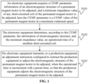
- FIG. 1 is a flowchart of a method for adjusting a permanent magnet motor according to an embodiment of the disclosure. As shown in FIG. 1 , the method of the embodiment may include the following operations.
- an electronic equipment acquires a CEMF parameter, information of an electromagnetic structure of a permanent magnet motor to be adjusted and a minimum impedance value of any short-circuited coil of the permanent magnet motor to be adjusted, here the CEMF parameter is a CEMF value of the permanent magnet motor at a maximum rotational speed.
- the electronic equipment acquires information such as the CEMF value of the permanent magnet motor to be adjusted at the maximum rotational speed, the minimum impedance value of any short-circuited coil, and the information of the electromagnetic structure, etc. in a manner of requesting from other equipments, reading from a memory, obtaining through an input, or the like. No limitations are made thereto in the disclosure.
- the electronic equipment further acquires an operational time of the short-circuited coil when an inter-turn short circuit occurs to the permanent magnet motor to be adjusted at the maximum rotational speed, according to the information.
- the CEMF parameter is a CEMF value generated by the coil by cutting a magnetic induction line of a magnetic pole during the operation of the permanent magnet motor to be adjusted.
- the electronic equipment may transmit an acquisition instruction to a test permanent magnet motor, and receive the CEMF parameter returned by the test permanent magnet motor according to the acquisition instruction.
- the CEMF value of the permanent magnet motor at the maximum rotational speed is determined through a simulation technology.
- the test permanent magnet motor is a permanent magnet motor with the same information of an electromagnetic structure as the permanent magnet motor to be adjusted.
- the electronic equipment may acquire the CEMF parameter from the test permanent magnet motor as follows.
- the electronic equipment transmits an acquisition instruction to a voltage measurement device on the test permanent magnet motor, and acquires the CEMF value, measured by the voltage measurement device, of the test permanent magnet motor at the maximum rotational speed.
- the electronic equipment may also simulate, through the simulation technology and according to the information of the electromagnetic structure of the permanent magnet motor to be adjusted, the permanent magnet motor to be adjusted and an operational condition of the permanent magnet motor to be adjusted at the maximum rotational speed in an environment such as a simulation software, etc., to further determine the CEMF value of the permanent magnet motor to be adjusted at the maximum rotational speed.
- the permanent magnet motor to be adjusted may have at least one coil which may be arranged on the stator.
- the coil of the permanent magnet motor generates a magnetic field when a current flows through the coil, and the rotor rotates under the interaction of a magnetic field of a magnetic pole and the magnetic field of the coil to implement the electric energy conversion or transmission of the permanent magnet motor.
- the minimum impedance value of any short-circuited coil is an impedance value of any turn of the wire in the coil.
- the coil in the permanent magnet motor may also be arranged on the rotor. In such case, a permanent magnet is arranged on the stator.
- the information of the electromagnetic structure of the permanent magnet motor to be adjusted includes one or more of: information of a cooling structure of the permanent magnet motor, a melting point of an insulating material, a permanent magnet parameter, a slot shape parameter of the motor, an electromagnetic wire parameter, etc.
- the cooling structure of the permanent magnet motor is configured to cool the permanent magnet motor.
- the information of the cooling structure of the permanent magnet motor includes cooling efficiency, a cooling manner, etc.
- the insulating material is used for insulation protection over the wire on the coil of the permanent magnet motor.
- a permanent magnet is used for the rotor of the permanent magnet motor.
- the permanent magnet parameter includes the magnetic performance, size, etc., of the permanent magnet.
- the electronic equipment determines, according to the CEMF parameter, the information of the electromagnetic structure and the minimum impedance value, an operational time of a smallest short-circuited coil.
- the electronic equipment imports the information to a parameter model, and obtains the operational time of the short-circuited coil through the parameter model.
- the parameter model may be a mapping relationship model, or an algorithm model.
- the electronic equipment transmits, to a production equipment, an adjustment instruction configured to instruct the production equipment to adjust the electromagnetic structure of the permanent magnet motor to be adjusted, when the operational time is inconsistent with a preset time, so that the production equipment adjusts the electromagnetic structure of the permanent magnet motor to be adjusted.
- the electronic equipment acquires the operational time of the short-circuited coil of the permanent magnet motor to be adjusted from the operation S102.
- the electronic equipment compares the operational time and the preset time.
- the operational time is more than or equal to the preset time, it is considered that the electromagnetic structure of the permanent magnet motor to be adjusted satisfies a condition and is not required to be adjusted.
- the preset time is one hour
- the operational time of the short-circuited coil is three hours, then it is considered that the electromagnetic structure of the permanent magnet motor to be adjusted satisfies the condition and is not required to be adjusted.
- the operational time is shorter than the preset time, it is considered that the electromagnetic structure of the permanent magnet motor to be adjusted does not satisfy the condition and is required to be adjusted.
- the preset time is one hour
- the operational time of the short-circuited coil is half an hour, then it is considered that the electromagnetic structure of the permanent magnet motor to be adjusted does not satisfy the condition and is required to be adjusted.
- the electronic equipment transmits the adjustment instruction to the production equipment when determining that the electromagnetic structure of the permanent magnet motor to be adjusted is required to be adjusted.
- the production equipment adjusts the electromagnetic structure of the permanent magnet motor to be adjusted according to the adjustment instruction, after receiving the adjustment instruction transmitted by the electronic equipment.
- the adjustment instruction is specifically configured to instruct the production equipment to perform one or more of: adjusting the permanent magnet parameter, replacing the insulating material, adjusting a cooling structure of the motor, adjusting the slot shape parameter, adjusting the electromagnetic wire parameter, etc., on the permanent magnet motor to be adjusted.
- the permanent magnet parameter and the electromagnetic structure determine an intensity of the magnetic field of the magnetic pole.
- the intensity of the magnetic field is higher at the same rotational speed, then the CEMF value generated by the coil by cutting the magnetic induction line is greater.
- reduction of the CEMF value in the permanent magnet motor where the inter-turn short circuit occurs may effectively prolong the operational time of the short-circuited coil of the permanent magnet motor. Therefore, reduction of the permanent magnet parameter in the permanent magnet motor may effectively prolong the operational time of the short-circuited coil of the permanent magnet motor, optimize the permanent magnet motor, and improve the safety of the permanent magnet motor.
- the reduction of the permanent magnet parameter may affect the electromagnetic performance of the permanent magnet motor.
- a reluctance torque e.g., a permanent magnet assisted reluctance motor, may further be increased on the basis of reducing the permanent magnet parameter, to ensure the electromagnetic performance.
- the insulating material is used for the wire of the coil. After the inter-turn short circuit occurs to the permanent magnet motor, the short-circuited coil converts electric energy into heat energy under the CEMF and the resistance of the short-circuited coil, which causes the temperature of the coil rising continuously.
- the insulating material may be molten due to the over-temperature of the coil to further aggravate the short circuit failure of the coil. Therefore, replacing the insulating material of the permanent magnet motor to improve the heat resistance class and heat dissipation performance of the insulating material may ensure that the short-circuited coil of the permanent magnet motor operates for a longer time, optimize the permanent magnet motor, and improve the safety of the permanent magnet motor.
- the cooling structure of the permanent magnet motor is configured to cool the permanent magnet motor. After the inter-turn short circuit occurs to the permanent magnet motor, the short-circuited coil converts electric energy into heat energy under the CEMF and the resistance of the short-circuited coil, which causes the temperature of the coil rising continuously.
- the cooling structure of the permanent magnet motor may be configured to dissipate heat by ventilation, heat conduction, and other manners to control the temperature of the permanent magnet motor and avoid an over-temperature. Therefore, adjusting the cooling structure of the permanent magnet motor to enhance the heat dissipation effect of the cooling structure of the permanent magnet motor may ensure that the short-circuited coil of the permanent magnet motor operates for a longer time, optimize the permanent magnet motor, and improve the safety of the permanent magnet motor.
- adjusting the electromagnetic structure of the permanent magnet motor may further include adjusting the slot shape parameter, adjusting the electromagnetic wire parameter, adjusting the turns of the coil, changing a wire material, etc.
- the electronic equipment acquires the CEMF parameter, the information of the electromagnetic structure of the permanent magnet motor to be adjusted and the minimum impedance value of any short-circuited coil of the permanent magnet motor to be adjusted, to determine the operational time of the short-circuited coil.
- the electronic equipment further judges, according to the operational time of the short-circuited coil, whether the adjustment instruction is required to be transmitted to the production equipment. When the operational time is inconsistent with the preset time, the electronic equipment transmits the adjustment instruction to the production equipment.
- the production equipment adjusts, according to the adjustment instruction, the electromagnetic structure of the permanent magnet motor to be adjusted.
- the operational time of the short-circuited coil is acquired to judge whether the permanent magnet motor to be adjusted may operate for the preset time safely, and the adjustment instruction is transmitted, according to a judgment result, to the production equipment of the permanent magnet motor to be adjusted, to implement optimization and adjustment of the permanent magnet motor.
- the short-circuited coil of the permanent magnet motor may operate for a longer time, the permanent magnet motor is optimized, and the safety of the permanent magnet motor is improved.
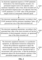
- FIG. 2 is a flowchart of another method for adjusting a permanent magnet motor according to an embodiment of the disclosure. As shown in FIG. 2 , the method of the embodiment may include the following operations.
- An implementation of the operation S201 is similar to that of the operation S101 in the embodiment shown in FIG. 1 , and will not be elaborated in the embodiment.
- the electronic equipment determines, according to the CEMF parameter and the minimum impedance value, a generated heat value of the short-circuited coil.
- the electronic equipment acquires the CEMF parameter and the minimum impedance value from the operation S201.
- a CEMF acts on the short-circuited coil to convert electric energy into heat energy.
- Q is the generated heat value in Joule.
- V is the CEMF value in volt.
- R is a resistance value in ohm.
- t is the unit time, i.e., one hour.
- the electronic equipment determines, according to the generated heat value of the short-circuited coil and the information of the electromagnetic structure, an operational time of the short-circuited coil.
- the information of the electromagnetic structure of the permanent magnet motor includes information of cooling electromagnetic structure of the permanent magnet motor, a melting point of an insulating material, a permanent magnet parameter, a slot shape parameter of the motor, an electromagnetic wire parameter, etc.
- the electronic equipment acquires the generated heat value of the short-circuited coil in the unit time according to the operation S202, and acquire a heat dissipation value generated by a cooling electromagnetic structure of the permanent magnet motor in the unit time according to the information of cooling electromagnetic structure of the permanent magnet motor.
- the electronic equipment calculates a practical generated heat value of the permanent magnet motor according to the generated heat value and the heat dissipation value.
- the practical generated heat value is a generated heat value that may still be accumulated after the interaction of heating and heat dissipation. With the accumulation of this part of generated heat value, the temperature of the permanent magnet motor may rise continuously.
- a high enough temperature of the permanent magnet motor may cause the insulating material melting and the coil fusing, to further bring the safety problem of the permanent magnet motor. Therefore, an operational time of the permanent magnet motor before reaching the high enough temperature is the operational time of the short-circuited coil of the permanent magnet motor.
- the temperature value may be an empirical value, and it is determined empirically that the permanent magnet motor is easily damaged after reaching the temperature.
- the temperature value may also be a calculated value, and it is calculated according to melting points of the insulating material, a wire material, etc.
- the temperature value may also be a trial value, and it is determined according to tests that the permanent magnet motor is easily damaged after reaching the temperature.
- the electronic equipment transmits, to a production equipment, an adjustment instruction configured to instruct the production equipment to adjust the electromagnetic structure of the permanent magnet motor to be adjusted, when the operational time is inconsistent with a preset time, so that the production equipment adjusts the electromagnetic structure of the permanent magnet motor to be adjusted.
- An implementation of the operation S204 is similar to that of the operation S103 in the embodiment shown in FIG. 1 , and will not be elaborated in the embodiment.
- the electronic equipment acquires the CEMF parameter and the minimum impedance value of any short-circuited coil of the permanent magnet motor to be adjusted, to determine the generated heat value of the short-circuited coil.
- the electronic equipment determines, according to the generated heat value of the short-circuited coil and the information of the electromagnetic structure of the permanent magnet motor to be adjusted, the operational time during which no safety problem may be brought to the short-circuited coil.
- the electronic equipment further judges, according to the operational time of the short-circuited coil, whether the adjustment instruction is required to be transmitted to the production equipment. When the operational time is inconsistent with the preset time, the electronic equipment transmits the adjustment instruction to the production equipment.
- the production equipment adjusts, according to the adjustment instruction, the electromagnetic structure of the permanent magnet motor to be adjusted.
- the electronic equipment calculates the generated heat value of the short-circuited coil according to the CEMF parameter and the minimum impedance value.
- the electronic equipment determines, according to the generated heat value and the electromagnetic structure parameter of the permanent magnet motor, the operational time of the short-circuited coil.
- the electronic equipment optimizes and adjusts, according to the operational time, the permanent magnet motor to be adjusted. As such, the short-circuited coil of the permanent magnet motor may operate for a longer time, the permanent magnet motor is optimized, and the safety of the permanent magnet motor is improved.
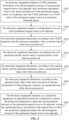
- FIG. 3 is a flowchart of another method for adjusting a permanent magnet motor according to an embodiment of the disclosure. As shown in FIG. 3 , the method of the embodiment may include the following operations.
- an electronic equipment acquires a CEMF parameter, information of an electromagnetic structure of a permanent magnet motor to be adjusted and a minimum impedance value of any short-circuited coil of the permanent magnet motor to be adjusted, here the CEMF parameter is a CEMF value of the permanent magnet motor at a maximum rotational speed.
- An implementation of the operation S301 is similar to that of the operation S101 in the embodiment shown in FIG. 1 , and will not be elaborated in the embodiment.
- the electronic equipment acquires a coil parameter of a coil of the permanent magnet motor to be adjusted.
- the electronic equipment may acquire the coil parameter of the coil corresponding to the permanent magnet motor to be adjusted, by reading from a memory.
- the electronic equipment may also acquire the coil parameter of the coil corresponding to the permanent magnet motor to be adjusted, according to input information. No limitations are made thereto in the disclosure.
- the coil parameter of the coil of the permanent magnet motor includes a cross-sectional area of a wire, resistivity of the wire, a length of the wire, turns of the coil, etc.
- the electronic equipment determines, according to the CEMF parameter and the minimum impedance value, a current value of the short-circuited coil.
- the short-circuited coil generates the current value under the CEMF.
- the current value is a quotient of the CEMF value over the minimum impedance value.
- the electronic equipment determines, according to the coil parameter and the current value, a current density of the short-circuited coil.
- the current density of the short-circuited coil is a value of a current flowing through a unit area.
- the current density is a ratio of the current of the short-circuited coil to the cross-sectional area of the wire.
- the electronic equipment determines, according to the current density and the minimum impedance value, a generated heat value of the short-circuited coil.
- Q is the generated heat value in Joule.
- I is the current value in Ampere.
- R is a resistance value in ohm.
- t is the unit time, i.e., one hour.
- the electronic equipment determines, according to the generated heat value of the short-circuited coil and the information of the electromagnetic structure, an operational time of the short-circuited coil.
- An implementation of the operation S306 is similar to that of the operation S203 in the embodiment shown in FIG. 2 , and will not be elaborated in the embodiment.
- the electronic equipment transmits, to a production equipment, an adjustment instruction configured to instruct the production equipment to adjust the electromagnetic structure of the permanent magnet motor to be adjusted, when the operational time is inconsistent with a preset time, so that the production equipment adjusts the electromagnetic structure of the permanent magnet motor to be adjusted.
- An implementation of the operation S307 is similar to that of the operation S103 in the embodiment shown in FIG. 1 , and will not be elaborated in the embodiment.
- the electronic equipment acquires the CEMF parameter, the minimum impedance value and the coil parameter of any short-circuited coil of the permanent magnet motor to be adjusted, to calculate the current value and the current density.
- the electronic equipment determines, according to the current value, the current density and the minimum impedance value, the generated heat value of the short-circuited coil in the unit time.
- the electronic equipment determines, according to the generated heat value and the information of the electromagnetic structure of the permanent magnet motor to be adjusted, the operational time of the short-circuited coil.
- the electronic equipment further judges, according to the operational time, whether the adjustment instruction is required to be transmitted to the production equipment.
- the electronic equipment transmits the adjustment instruction to the production equipment.
- the production equipment adjusts, according to the adjustment instruction, the electromagnetic structure of the permanent magnet motor to be adjusted.
- the electronic equipment calculates the current value, the current density, and the generated heat value of the short-circuited coil in the unit time, calculates the operational time of the short-circuited coil according to the generated heat value and the electromagnetic structure parameter of the permanent magnet motor, and further optimizes and adjusts the permanent magnet motor to be adjusted according to the operational time.
- the short-circuited coil of the permanent magnet motor may operate for a longer time, the permanent magnet motor is optimized, and the safety of the permanent magnet motor is improved.
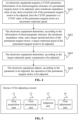
- the method for adjusting a permanent magnet motor may also be configured to adjust a rotational speed of the permanent magnet motor, to ensure that the train may smoothly arrive the destination.
- An implementation of the operation S401 is similar to that of the operation S101 in the embodiment shown in FIG. 1 , and will not be elaborated in the embodiment.
- the electronic equipment determines, according to the information of the electromagnetic structure, the minimum impedance value, and a target operational time of the permanent magnet motor, a target rotational speed of the permanent magnet motor to be adjusted.
- the rotational speed of the permanent magnet motor is calculated through the following operations.
- the electronic equipment acquires a maximum temperature reachable for the permanent magnet motor to be adjusted, and determines, according to the temperature and a current temperature of the permanent magnet motor, a temperature variation of the permanent magnet motor.
- the electronic equipment determines, according to the temperature variation and target operational time of the permanent magnet motor, a practical generated heat value of the short-circuited coil of the permanent magnet motor in a unit time.
- the electronic equipment determines, according to the practical generated heat value and a heat dissipation value of a cooling electromagnetic structure of the permanent magnet motor in the unit time in the information of the electromagnetic structure , a generated heat value of the short-circuited coil in the unit time.
- the electronic equipment determines, according to the generated heat value and the minimum impedance value, a CEMF value of the short-circuited coil.
- the electronic equipment determines, according to a coil parameter, the CEMF value, and the information of the electromagnetic structure of the permanent magnet motor, the target rotational speed of the permanent magnet motor.
- the coil parameter includes turns of the coil, resistivity of the wire, etc.
- the information of the electromagnetic structure of the permanent magnet motor includes a permanent magnet parameter, etc.
- the electronic equipment determines, according to the target rotational speed, a parameter to be adjusted.
- the electronic equipment calculates, according to the target rotational speed calculated in the operation S402, a running speed of the rail transit vehicle at the target rotational speed, and determine, according to the running speed, a parameter required to be adjusted.
- the electronic equipment adjusts, according to the parameter to be adjusted, the operation of the permanent magnet motor to be adjusted.
- the rail transit vehicle includes multiple permanent magnet motors.
- the electronic equipment adjusts other permanent magnet motors of the rail transit vehicle according to the parameter to be adjusted determined in the operation S403, to reduce the running speed of the rail transit vehicle to a safe running speed, to further ensure that the rotational speed of the permanent magnet motor to be adjusted is less than or equal to the target rotational speed.
- the electronic equipment determines, according to the information of the electromagnetic structure, the minimum impedance value, and a preset operational time of the permanent magnet motor, the target rotational speed of the permanent magnet motor to be adjusted, and further determines the parameter to be adjusted of the rail transit vehicle according to the target rotational speed, to make an adjusted rotational speed of the permanent magnet motor of the rail transit vehicle less than or equal to the target rotational speed.
- the electronic equipment adjusts the running speed of the rail transit vehicle to make the operational time of the permanent magnet motor where the inter-turn short circuit occurs equal to the target operational time, to ensure that the rail transit vehicle may keep running to the destination safely after the inter-turn short circuit failure occurs to the permanent magnet motor, to further ensure the safety of a person or goods in the rail transit vehicle, and improve the safety of the rail transit vehicle.
- FIG. 5 is a schematic diagram of electromagnetic structure of a device for adjusting a permanent magnet motor according to an embodiment of the disclosure.
- the device for adjusting a permanent magnet motor 10 of the embodiment is configured to implement the operations corresponding to the electronic equipment in any of the above-mentioned method embodiments.
- the device for adjusting a permanent magnet motor 10 of the embodiment may include a first acquisition unit 11, a first processing unit 12, a judgment unit 13, and a first adjustment unit 14.
- the first acquisition unit 11 is configured to acquire a CEMF parameter, information of an electromagnetic structure of a permanent magnet motor to be adjusted and a minimum impedance value of any short-circuited coil of the permanent magnet motor to be adjusted, here the CEMF parameter is a CEMF value of the permanent magnet motor at a maximum rotational speed.
- the first processing unit 12 is configured to determine, according to the CEMF parameter, the information of the electromagnetic structure and the minimum impedance value, an operational time of the short-circuited coil.
- the judgment unit 13 is configured to judge whether the operational time is consistent with a preset time.
- the first adjustment unit 14 is configured to transmit, to a production equipment, an adjustment instruction configured to instruct the production equipment to adjust the electromagnetic structure of the permanent magnet motor to be adjusted, when the operational time is inconsistent with the preset time, so that the production equipment adjusts the electromagnetic structure of the permanent magnet motor to be adjusted.
- the device for adjusting a permanent magnet motor 10 provided in the embodiment of the disclosure may execute the above-mentioned method embodiments, and a specific implementation principle and technical effect thereof may refer to the above-mentioned method embodiments, and will not be elaborated in the embodiment.
- FIG. 6 is a schematic diagram of electromagnetic structure of another device for adjusting a permanent magnet motor according to an embodiment of the disclosure.
- the device for adjusting a permanent magnet motor 10 of the embodiment is configured to implement the operations corresponding to the electronic equipment in any of the above-mentioned method embodiments.
- the first acquisition unit 11 when configured to acquire the CEMF parameter, is specifically configured to: transmit an acquisition instruction to a permanent magnet motor, and receive the CEMF parameter returned by the permanent magnet motor according to the acquisition instruction; or, determine, through a simulation technology, the CEMF value of the permanent magnet motor at the maximum rotational speed.
- the first processing unit 12 includes a first determination module 22 and a second determination module 23.
- the first determination module 22 is configured to determine, according to the CEMF parameter and the minimum impedance value, a generated heat value of the short-circuited coil.
- the second determination module 23 is configured to determine, according to the generated heat value of the short-circuited coil and the information of the electromagnetic structure, the operational time of the short-circuited coil.
- the device for adjusting a permanent magnet motor 10 provided in the embodiment of the disclosure may execute the above-mentioned method embodiments, and a specific implementation principle and technical effect thereof may refer to the above-mentioned method embodiments, and will not be elaborated in the embodiment.
- FIG. 7 is a schematic diagram of electromagnetic structure of another device for adjusting a permanent magnet motor according to an embodiment of the disclosure. Based on the embodiments shown in FIGS. 5 and 6 , as shown in FIG. 7 , the device for adjusting a permanent magnet motor 10 of the embodiment is configured to implement the operations corresponding to the electronic equipment in any of the above-mentioned method embodiments.
- the device for adjusting a permanent magnet motor 10 of the embodiment may further include a second acquisition unit 15.
- the second acquisition unit 15 is configured to acquire a coil parameter of a coil of the permanent magnet motor to be adjusted.
- the first determination module 22 includes a first determination submodule 33, a second determination submodule 34, and a third determination submodule 35.
- the first determination submodule 33 is configured to determine, according to the CEMF parameter and the minimum impedance value, a current value of the short-circuited coil.
- the second determination submodule 34 is configured to determine, according to the coil parameter and the current value, a current density of the short-circuited coil.
- the third determination submodule 35 is configured to determine, according to the current density and the minimum impedance value, the generated heat value of the short-circuited coil.
- the information of the electromagnetic structure of the permanent magnet motor to be adjusted includes one or more of: information of cooling electromagnetic structure of the permanent magnet motor, a melting point of an insulating material, a permanent magnet parameter, a slot shape parameter of the permanent magnet motor, an electromagnetic wire parameter, etc.
- the adjustment instruction is specifically configured to instruct the production equipment to perform one or more of: adjusting the permanent magnet parameter, replacing the insulating material, adjusting a cooling electromagnetic structure of the permanent magnet motor, adjusting the slot shape parameter of the permanent magnet motor, adjusting the electromagnetic wire parameter, etc., on the permanent magnet motor to be adjusted.
- the device for adjusting a permanent magnet motor 10 provided in the embodiment of the disclosure may execute the above-mentioned method embodiments, and a specific implementation principle and technical effect thereof may refer to the above-mentioned method embodiments, and will not be elaborated in the embodiment.
- FIG. 8 is a schematic diagram of electromagnetic structure of another device for adjusting a permanent magnet motor according to an embodiment of the disclosure. Based on the embodiment shown in FIG. 5 , as shown in FIG. 8 , when the rail transit vehicle runs, the device for adjusting a permanent magnet motor 10 of the embodiment is configured to implement the operations corresponding to the electronic equipment in any of the above-mentioned method embodiments.
- the device for adjusting a permanent magnet motor 10 of the embodiment may further include a second processing unit 41, a determination unit 42, and a second adjustment unit 43.
- the second processing unit 41 is configured to determine, according to the information of the electromagnetic structure, the minimum impedance value, and a target operational time of the permanent magnet motor, a target rotational speed of the permanent magnet motor to be adjusted.
- the second adjustment unit 43 is configured to adjust, according to the parameter to be adjusted, the operation of the permanent magnet motor to be adjusted.
- the device for adjusting a permanent magnet motor 10 provided in the embodiment of the disclosure may execute the above-mentioned method embodiments, and a specific implementation principle and technical effect thereof may refer to the above-mentioned method embodiments, and will not be elaborated in the embodiment.
- each functional unit may be divided by way of corresponding to each function, or two or more functions may be integrated into a processing unit.
- the integrated unit may be implemented in a hardware form, or may be implemented in form of a software functional unit. It is to be noted that the division of units in each embodiment of the disclosure is schematic and is only a logical function division, and other division manners may be adopted during practical implementation.
- FIG. 9 is a schematic diagram of hardware electromagnetic structure of an electronic equipment according to an embodiment not being part of the invention
- the electronic equipment 50 is configured to implement the operations corresponding to the electronic equipment in any of the above-mentioned method embodiments.
- the electronic equipment 50 of the embodiment may include a memory 51, a processor 52, and a communication interface 54.
- the memory 51 is configured to store a computer program.
- the processor 52 is configured to execute the computer program stored in the memory to implement the method for adjusting a permanent magnet motor in the above-mentioned embodiments. References may specifically be made to the related descriptions in the above-mentioned method embodiments.
- the memory 51 may be independent, or may be integrated with the processor 52.
- the electronic equipment 50 may further include a bus 53.
- the bus 53 is configured to connect the memory 51 with the processor 52.
- the embodiment not being part of the invention further includes the communication interface 54 which may be connected with the processor 51 through the bus 53.
- the processor 52 may control the communication interface 54 to realize receiving and transmitting functions of the electronic equipment 50.
- the electronic equipment provided in the embodiment not being part of the invention may be configured to execute the method for adjusting a permanent magnet motor, and an implementation and technical effect thereof are similar, and will not be elaborated in the embodiment.
- the disclosure also provides a computer-readable storage medium including a computer program which is configured to implement the method for adjusting a permanent magnet motor in the above-mentioned embodiments.
- the disclosed device and method may be implemented in other manners.
- the device embodiment as described above is only schematic, and for example, the division of modules is only a logical function division, and other division manners may be adopted during practical implementation. For example, multiple modules may be combined or integrated into another system, or some characteristics may be neglected or may not be executed.
- coupling or direct coupling or communication connection between each displayed or discussed component may be indirect coupling or communication connection implemented through some interfaces, devices or modules, and may be electrical and mechanical or adopt other forms.
- modules described as separate parts may be or may not be physically separated, and parts displayed as modules may be or may not be physical units, namely, they may be located in the same place, or may be distributed to multiple network units. Part or all of the modules may be selected to achieve the purposes of the solutions of the embodiments as required.
- each function module in each embodiment of the disclosure may be integrated into a processing module, or each module may physically exist independently, or two or more modules may be integrated into a module.
- the integrated module may be implemented in a hardware form, or may be implemented in form of hardware and software function unit.
- the integrated module implemented in form of a software function module may be stored in a computer-readable storage medium.
- the software function module is stored in a storage medium, including multiple instructions configured to enable a computer device (which may be a personal computer, a server, a network device, etc.) or a processor to execute part of the steps of the method in each embodiment of the disclosure.
- the processor may be a Central Processing Unit (CPU), or another general-purpose processor, a Digital Signal Processor (DSP), an Application Specific Integrated Circuit (ASIC), etc.
- the general-purpose processor may be a microprocessor, or the processor may be any conventional processor, etc.
- the steps of the method disclosed in combination with the disclosure may be directly embodied to be executed and completed by a hardware processor, or executed and completed by a combination of hardware and software modules in the processor.
- the memory may include a high-speed Random Access Memory (RAM), or may include a Non-Volatile Memory (NVM), such as at least one disk memory, or may be a U disk, a mobile hard disk, a Read-Only Memory (ROM), a magnetic disk, an optical disk, etc.
- RAM Random Access Memory
- NVM Non-Volatile Memory
- the bus may be an Industry Standard Architecture (ISA) bus, a Peripheral Component Interconnect (PCI) bus, an Extended Industry Standard Architecture (EISA) bus, etc.
- ISA Industry Standard Architecture
- PCI Peripheral Component Interconnect
- EISA Extended Industry Standard Architecture
- the bus may be divided into an address bus, a data bus, a control bus, etc.
- the bus in the drawings of the disclosure is not limited to one bus or one type of bus.
- the computer-readable storage medium may be implemented by any type of volatile or nonvolatile storage devices or a combination thereof, such as a Static Random-Access Memory (SRAM), an Electrically-Erasable Programmable Read-Only Memory (EEPROM), an Erasable Programmable Read-Only Memory (EPROM), a Programmable Read-Only Memory (PROM), a ROM, a magnetic memory, a flash memory, a magnetic disk, or an optical disk.
- SRAM Static Random-Access Memory
- EEPROM Electrically-Erasable Programmable Read-Only Memory
- EPROM Erasable Programmable Read-Only Memory
- PROM Programmable Read-Only Memory
- ROM Read-Only Memory
- the storage medium may be any available medium accessible for a general-purpose or special-purpose computer.
- the program may be stored in a computer-readable storage medium.
- the program is executed to execute the steps in the above-mentioned method embodiments.
- the storage medium includes various media capable of storing program codes such as a ROM, a RAM, a magnetic disk, or an optical disk, etc.
Landscapes
- Engineering & Computer Science (AREA)
- Power Engineering (AREA)
- Manufacturing & Machinery (AREA)
- Microelectronics & Electronic Packaging (AREA)
- Control Of Electric Motors In General (AREA)
- Manufacture Of Motors, Generators (AREA)
- Control Of Ac Motors In General (AREA)
- Control Of Linear Motors (AREA)
- Control Of Motors That Do Not Use Commutators (AREA)
Claims (3)
- Verfahren zur Justierung eines Permanentmagnetmotors auf einem Schienenverkehrsfahrzeug, das mehrere Permanentmagnetmotoren umfasst, wobei die Leistung des zu justierenden Motors abgeschaltet wird, wenn ein Windungskurzschluss auftritt, wobei das Verfahren Folgendes umfasst:- Erfassen, durch eine Steuereinrichtung, von einem gegenelektromotorischen Kraftparameter, CEMF, Informationen einer elektromagnetischen Struktur des zu justierenden Permanentmagnetmotors und einem Mindestimpedanzwert einer beliebigen kurzgeschlossenen Spule des zu justierenden Permanentmagnetmotors, wobei der CEMF-Parameter ein CEMF-Wert des Permanentmagnetmotors bei einer maximalen Drehzahl ist (S401);- Bestimmen, durch die Steuereinrichtung, gemäß den Informationen der elektromagnetischen Struktur, des Mindestimpedanzwerts, und einer Zielbetriebszeit des Permanentmagnetmotors, einer Zieldrehzahl des zu justierenden Permanentmagnetmotors, wobei die Zielbetriebszeit die Zeit ist, welche das Schienenverkehrsfahrzeug weiterhin betrieben werden muss, um ohne Schmelzen der kurzgeschlossenen Spule des Motors am Zielort einzutreffen;wobei die Zieldrehzahl des Permanentmagnetmotors durch die folgenden Vorgänge berechnet wird:in einem ersten Vorgang erfasst die Steuereinrichtung eine Höchsttemperatur, die für den zu justierenden Permanentmagnetmotor erreichbar ist, und bestimmt, gemäß der Höchsttemperatur und einer gegenwärtigen Temperatur des Permanentmagnetmotors, eine Temperaturschwankung des Permanentmagnetmotors,in einem zweiten Vorgang bestimmt die Steuereinrichtung, gemäß der Temperaturschwankung und Zielbetriebszeit des Permanentmagnetmotors, einen praktischen erzeugten Wärmewert der kurzgeschlossenen Spule des Permanentmagnetmotors in einer Zeiteinheit,in einem dritten Vorgang bestimmt die Steuereinrichtung, gemäß dem praktischen erzeugten Wärmewert und einem Wärmeableitungswert einer elektromagnetischen Kühlungsstruktur des Permanentmagnetmotors in der Zeiteinheit in den Informationen der elektromagnetischen Struktur, einen erzeugten Wärmewert der kurzgeschlossenen Spule in der Zeiteinheit,in einem vierten Vorgang bestimmt die Steuereinrichtung, gemäß dem erzeugten Wärmewert und dem Mindestimpedanzwert, einen CEMF-Wert der kurzgeschlossenen Spule,in einem fünften Vorgang bestimmt die Steuereinrichtung, gemäß einem Spulenparameter, den CEMF-Wert, und den Informationen der elektromagnetischen Struktur des Permanentmagnetmotors, die Zieldrehzahl des Permanentmagnetmotors,- Bestimmen, durch die Steuereinrichtung, gemäß der Zieldrehzahl, eines zu justierenden Parameters (S403), wobei die Steuereinrichtung, gemäß der Zieldrehzahl, eine Fahrgeschwindigkeit des Schienenverkehrsfahrzeugs bei der Zieldrehzahl berechnet und, gemäß der Fahrgeschwindigkeit, einen Parameter bestimmt, dessen Justieren erforderlich ist, wobei sichergestellt werden muss, dass die Drehzahl des zu justierenden Permanentmagnetmotors niedriger als die Zieldrehzahl ist, wenn das Schienenverkehrsfahrzeug fährt,- Justieren, durch die Steuereinrichtung, gemäß dem zu justierenden Parameter, des Betriebs des zu justierenden Permanentmagnetmotors (S404), wobei der Mindestimpedanzwert einer beliebigen kurzgeschlossenen Spule des zu justierenden Permanentmagnetmotors ein Impedanzwert einer beliebigen Windung eines Drahtes in der kurzgeschlossenen Spule ist;wobei die Informationen der elektromagnetischen Struktur des zu justierenden Permanentmagnetmotors die Informationen der Kühlungsstruktur des Motors, einen Schmelzpunkt des Isoliermaterials und einen oder mehrere von Folgendem umfassen: einen Permanentmagnetparameter, einen Nutformparameter des Motors oder einen elektromagnetischen Drahtparameter,wobei die Informationen der Kühlungsstruktur des Motors Folgendes umfassen: Kühleffizienz und eine Kühlungsweise, und der Permanentmagnetparameter magnetische Leistung und Größe umfasst, wobei der Spulenparameter eine Querschnittsfläche eines Drahtes, einen spezifischen Widerstand des Drahtes, eine Länge des Drahtes, Windungen der Spule umfasst.
- Vorrichtung (10) zum Justieren eines Permanentmagnetmotors, wobei die Vorrichtung zum Implementieren des Verfahrens nach Anspruch 1 ausgestaltet ist.
- Vorrichtung (10) nach Anspruch 2, wobei die Vorrichtung ferner dazu ausgestaltet ist, das folgende Verfahren zum Anweisen einer Herstellungsausrüstung zum Justieren eines Permanentmagnetmotors zu implementieren:- Erfassen von, durch eine Steuereinrichtung, einem gegenelektromotorischen Kraftparameter, CEMF, Informationen einer elektromagnetischen Struktur eines zu justierenden Permanentmagnetmotors und einem Mindestimpedanzwert einer beliebigen kurzgeschlossenen Spule des zu justierenden Permanentmagnetmotors, wobei der CEMF-Parameter ein CEMF-Wert des Permanentmagnetmotors bei einer maximalen Drehzahl ist (S101), und wobei der Mindestimpedanzwert einer beliebigen kurzgeschlossenen Spule des zu justierenden Permanentmagnetmotors ein Impedanzwert einer beliebigen Windung eines Drahtes in der kurzgeschlossenen Spule ist;- Bestimmen, durch die Steuereinrichtung gemäß dem CEMF-Parameter, der Informationen der elektromagnetischen Struktur und des Mindestimpedanzwerts, einer Betriebszeit der kurzgeschlossenen Spule (S102), wobei während der Betriebszeit der zu justierende Permanentmagnetmotor bei der Höchstdrehzahl betrieben wird und die kurzgeschlossene Spule nicht geschmolzen wird; und- Senden, durch die Steuereinrichtung an eine Herstellungsausrüstung, einer Justierungsanweisung, die dazu ausgestaltet ist, die Herstellungsausrüstung anzuweisen, die elektromagnetische Struktur des zu justierenden Permanentmagnetmotors zu justieren, wenn die Betriebszeit kürzer als eine voreingestellte Zeit ist, derart dass die Herstellungsausrüstung die elektromagnetische Struktur des zu justierenden Permanentmagnetmotors justiert (S103);wobei das Bestimmen, gemäß dem CEMF-Parameter, den Informationen der elektromagnetischen Struktur und dem Mindestimpedanzwert, der Betriebszeit der kurzgeschlossenen Spule Folgendes umfasst:Bestimmen eines Werts der erzeugten Wärme der kurzgeschlossenen Spule durch:
 wobei Q der Wert der erzeugten Wärme in Joule ist, V der CEMF-Wert in Volt ist, R der Widerstandswert in Ohm ist und t eine Zeiteinheit ist;Erfassen eines Wärmeableitungswerts, der durch eine elektromagnetische Kühlungsstruktur des Permanentmagnetmotors in der Zeiteinheit erzeugt wird, gemäß Informationen der elektromagnetischen Kühlungsstruktur;Berechnen eines praktischen erzeugten Wärmewerts des Permanentmagnetmotors gemäß dem erzeugten Wärmewert und dem Wärmeableitungswert, wobei eine Temperatur des Permanentmagnetmotors kontinuierlich mit einer Akkumulation des praktischen erzeugte Wärmewerts ansteigt;Erfassen eines Temperaturschwellenwerts, der das Schmelzen eines Isoliermaterials und das Schmelzen der kurzgeschlossenen Spule verursacht; undBestimmen der Betriebszeit der kurzgeschlossenen Spule, wobei die Betriebszeit der kurzgeschlossenen Spule eine Betriebszeit des Permanentmagnetmotors vor dem Erreichen des Temperaturschwellenwerts ist,wobei die Informationen der elektromagnetischen Struktur des zu justierenden Permanentmagnetmotors die Informationen der Kühlungsstruktur des Motors, einen Schmelzpunkt des Isoliermaterials und eines oder mehrere von Folgendem umfassen: einen Permanentmagnetparameter, einen Nutformparameter des Motors oder einen elektromagnetischen Drahtparameter,wobei die Informationen der Kühlungsstruktur des Motors Folgendes umfassen: Kühleffizienz und Kühlweise, und der Permanentmagnetparameter magnetische Leistung umfasst und der Permanentmagnetparameter magnetische Leistung und Größe umfasst,wobei das Justieren der elektromagnetischen Struktur des Permanentmagnetmotors das Justieren des Permanentmagnetparameters, das Ersetzen des Isoliermaterials, das Justieren einer Kühlungsstruktur des Permanentmagnetmotors, das Justieren des Nutformparameters des Permanentmagnetmotors, das Justieren des elektromagnetischen Drahtparameters, das Justieren der Windungen der Spule, das Ändern eines Drahtmaterials umfasst.
Applications Claiming Priority (2)
| Application Number | Priority Date | Filing Date | Title |
|---|---|---|---|
| CN202010175890.5A CN113394922B (zh) | 2020-03-13 | 2020-03-13 | 永磁电机调整方法、装置、设备以及存储介质 |
| PCT/CN2020/130540 WO2021179673A1 (zh) | 2020-03-13 | 2020-11-20 | 永磁电机调整方法、装置、设备以及存储介质 |
Publications (3)
| Publication Number | Publication Date |
|---|---|
| EP4060880A1 EP4060880A1 (de) | 2022-09-21 |
| EP4060880A4 EP4060880A4 (de) | 2023-01-11 |
| EP4060880B1 true EP4060880B1 (de) | 2025-03-19 |
Family
ID=77615981
Family Applications (1)
| Application Number | Title | Priority Date | Filing Date |
|---|---|---|---|
| EP20924123.1A Active EP4060880B1 (de) | 2020-03-13 | 2020-11-20 | Verfahren und vorrichtung zur justierung eines permanentmagnetmotors sowie vorrichtung und speichermedium |
Country Status (6)
| Country | Link |
|---|---|
| US (1) | US11863109B2 (de) |
| EP (1) | EP4060880B1 (de) |
| JP (1) | JP7398006B2 (de) |
| CN (1) | CN113394922B (de) |
| CA (1) | CA3157730A1 (de) |
| WO (1) | WO2021179673A1 (de) |
Families Citing this family (2)
| Publication number | Priority date | Publication date | Assignee | Title |
|---|---|---|---|---|
| CN115149753B (zh) * | 2022-07-27 | 2024-12-20 | 日照东方电机有限公司 | 一种永磁电机智能化维修防护方法及系统 |
| CN115824137A (zh) * | 2022-11-08 | 2023-03-21 | 重庆长安新能源汽车科技有限公司 | 定子热套的失效检测方法、装置、电子设备及存储介质 |
Citations (1)
| Publication number | Priority date | Publication date | Assignee | Title |
|---|---|---|---|---|
| US6759783B2 (en) * | 2000-02-19 | 2004-07-06 | Robert Bosch Gmbh | Electric motor, in particular for raising and lowering disks in motor vehicles |
Family Cites Families (21)
| Publication number | Priority date | Publication date | Assignee | Title |
|---|---|---|---|---|
| DE102006012215A1 (de) | 2006-03-16 | 2007-09-20 | Mtu Aero Engines Gmbh | Transversalflussmaschine und Turbomaschine mit derartiger Transversalflussmaschie |
| WO2009001468A1 (ja) | 2007-06-28 | 2008-12-31 | Mitsubishi Electric Corporation | 電力変換装置 |
| GB201005178D0 (en) | 2010-03-29 | 2010-05-12 | Rolls Royce Plc | Electrical machine safety system |
| JP5573498B2 (ja) | 2010-08-30 | 2014-08-20 | 富士電機株式会社 | 回転機の製造方法および回転機 |
| JP5781326B2 (ja) | 2011-02-25 | 2015-09-16 | Ntn株式会社 | 電気自動車 |
| JP6423264B2 (ja) | 2014-12-25 | 2018-11-14 | 株式会社Soken | 電力変換装置 |
| DE102015212856A1 (de) | 2015-07-09 | 2017-01-12 | Jungheinrich Aktiengesellschaft | Verfahren zur Herstellung einer elektrischen Maschine mit flexiblem Rotor und Fahrzeug umfassend eine solche |
| CN105515321A (zh) * | 2015-12-31 | 2016-04-20 | 万向钱潮传动轴有限公司 | 一种电机直接驱动的电动转向装置 |
| CN106385208A (zh) * | 2016-11-29 | 2017-02-08 | 深圳市道通智能航空技术有限公司 | 一种永磁同步电机启动方法、装置和无人飞行器 |
| CN106844923B (zh) | 2017-01-12 | 2020-11-06 | 中国人民解放军海军工程大学 | 一种多相永磁电机的参数化设计方法 |
| JP6936759B2 (ja) * | 2018-03-30 | 2021-09-22 | 三菱重工業株式会社 | 診断装置、駆動システム、診断方法及びプログラム |
| CN108512469B (zh) | 2018-04-02 | 2019-11-12 | 南京航空航天大学 | 一种具有容错能力的永磁起动发电系统及其控制方法 |
| CN108875255B (zh) | 2018-07-04 | 2022-08-16 | 黑龙江科技大学 | 基于电动汽车实际行驶工况的永磁驱动电机温升分析方法 |
| CN109167545B (zh) * | 2018-09-14 | 2022-02-18 | 新疆大学 | 永磁同步发电机磁链在线辨识方法与系统 |
| CN109061475B (zh) * | 2018-11-01 | 2021-09-10 | 上海科梁信息科技股份有限公司 | 永磁同步电机匝间短路故障模拟方法、装置、系统、介质 |
| WO2020215154A1 (en) * | 2019-04-23 | 2020-10-29 | Dpm Technologies Inc. | Fault tolerant rotating electric machine |
| CN110022099A (zh) * | 2019-04-29 | 2019-07-16 | 青岛海信日立空调系统有限公司 | 一种永磁同步电机失步的检测方法及装置 |
| US10756659B1 (en) * | 2019-04-30 | 2020-08-25 | Rockwell Automation Technologies, Inc. | Counter electromotive force estimation |
| CN110212710B (zh) | 2019-06-17 | 2020-05-08 | 北京理工大学 | 一种车用永磁同步电机设计方法 |
| CN110417199B (zh) | 2019-07-10 | 2021-01-26 | 贵州航天林泉电机有限公司 | 一种基于区间频率的抗短路永磁发电机设计方法 |
| CN112542910A (zh) | 2019-09-20 | 2021-03-23 | 中车永济电机有限公司 | 电机转子和电机 |
-
2020
- 2020-03-13 CN CN202010175890.5A patent/CN113394922B/zh active Active
- 2020-11-20 JP JP2022551427A patent/JP7398006B2/ja active Active
- 2020-11-20 CA CA3157730A patent/CA3157730A1/en active Pending
- 2020-11-20 US US17/784,211 patent/US11863109B2/en active Active
- 2020-11-20 EP EP20924123.1A patent/EP4060880B1/de active Active
- 2020-11-20 WO PCT/CN2020/130540 patent/WO2021179673A1/zh not_active Ceased
Patent Citations (1)
| Publication number | Priority date | Publication date | Assignee | Title |
|---|---|---|---|---|
| US6759783B2 (en) * | 2000-02-19 | 2004-07-06 | Robert Bosch Gmbh | Electric motor, in particular for raising and lowering disks in motor vehicles |
Non-Patent Citations (5)
| Title |
|---|
| ARUMUGAM PUVAN ET AL: "A review on turn-turn short circuit fault management", 2015 INTERNATIONAL CONFERENCE ON ELECTRICAL SYSTEMS FOR AIRCRAFT, RAILWAY, SHIP PROPULSION AND ROAD VEHICLES (ESARS), IEEE, 3 March 2015 (2015-03-03), pages 1 - 5, XP032774274, DOI: 10.1109/ESARS.2015.7101528 * |
| CINTRON-RIVERA JORGE G ET AL: "Mitigation of Turn-to-Turn Faults in Fault Tolerant Permanent Magnet Synchronous Motors", IEEE TRANSACTIONS ON ENERGY CONVERSION, IEEE SERVICE CENTER, PISCATAWAY, NJ, US, vol. 30, no. 2, 1 June 2015 (2015-06-01), pages 465 - 475, XP011581368, ISSN: 0885-8969, [retrieved on 20150515], DOI: 10.1109/TEC.2014.2360813 * |
| DUSEK JIRI ET AL: "Impact of Slot/Pole Combination on Inter-Turn Short-Circuit Current in Fault-Tolerant Permanent Magnet Machines", IEEE TRANSACTIONS ON MAGNETICS, IEEE, USA, vol. 52, no. 4, 1 April 2016 (2016-04-01), pages 1 - 9, XP011603107, ISSN: 0018-9464, [retrieved on 20160316], DOI: 10.1109/TMAG.2015.2500894 * |
| HONGBO QIU ET AL: "Research on the Influence of Inter-turn Short Circuit Fault on the Temperature Field of Permanent Magnet Synchronous Motor", JOURNAL OF ELECTRICAL ENGINEERING & TECHNOLOGY, 1 January 2017 (2017-01-01), pages 1566 - 1574, XP093080405, Retrieved from the Internet <URL:unknown> [retrieved on 20230908], DOI: 10.5370/JEET.2017.12.4.1566 * |
| SOULARD JULIETTE: "System Analysis of Permanent Magnet Traction Drives", 19 December 2012 (2012-12-19), XP093080407, Retrieved from the Internet <URL:https://www.diva-portal.org/smash/record.jsf?pid=diva2%3A606229&dswid=4364> [retrieved on 20230908] * |
Also Published As
| Publication number | Publication date |
|---|---|
| JP2023500419A (ja) | 2023-01-05 |
| EP4060880A1 (de) | 2022-09-21 |
| EP4060880A4 (de) | 2023-01-11 |
| CN113394922B (zh) | 2022-06-14 |
| CN113394922A (zh) | 2021-09-14 |
| WO2021179673A1 (zh) | 2021-09-16 |
| US11863109B2 (en) | 2024-01-02 |
| CA3157730A1 (en) | 2021-09-16 |
| JP7398006B2 (ja) | 2023-12-13 |
| US20230039034A1 (en) | 2023-02-09 |
Similar Documents
| Publication | Publication Date | Title |
|---|---|---|
| US8482237B2 (en) | Motor temperature estimation based on thermal model | |
| CN116985640B (zh) | 一种电驱动系统、动力总成、加热方法及电动车辆 | |
| US8773058B2 (en) | Rotor temperature estimation and motor control torque limiting for vector-controlled AC induction motors | |
| US11863109B2 (en) | Method and device for adjusting permanent magnet motor, equipment, and storage medium | |
| US9178404B2 (en) | Liquid-cooled self-excited eddy current retarder with a structure of two salient poles | |
| WO2012098978A1 (ja) | 車載回転電機用電力変換装置の冷却システム | |
| CN104854775B (zh) | 最佳地分配定子和转子之间的电损失的异步电机 | |
| CN110212710A (zh) | 一种车用永磁同步电机设计方法 | |
| Ranjan et al. | Comprehensive analysis of thermal effects on pmsm drive control in small commercial vehicles | |
| Cinti et al. | Performance and short-circuit fault analysis in hybrid excited and interior PM motors | |
| Li et al. | Influence of direct‐connected inverter with one power switch open circuit fault on electromagnetic field and temperature field of permanent magnet synchronous motor | |
| Nitsche et al. | Internally cooled hollow wires doubling the power density of electric motors | |
| CN101693445A (zh) | 一种无速度传感器交流牵引传动系统过电分相方法 | |
| CN115808658A (zh) | 一种雷达系统自加热方法、雷达系统及终端设备 | |
| CN209345046U (zh) | 一种无刷直流电机制动电路 | |
| JP7248456B2 (ja) | 制御装置、巻線切替モータシステム、制御方法及びプログラム | |
| JP2016122494A (ja) | バッテリ冷却装置 | |
| Finken et al. | Design and optimization of an IPMSM with fixed outer dimensions for application in HEVs | |
| KR20170006008A (ko) | 모터 구동 인버터용 션트저항 내장형 버스바 | |
| CN103378778B (zh) | 一种电动车、无刷直流电机及其驱动控制系统 | |
| JP2016115608A (ja) | バッテリ冷却装置 | |
| Towhidi et al. | Lumped parameter thermal network modeling for online temperature prediction of permanent magnet synchronous motor for different drive cycles in electric vehicle applications | |
| Hoffmann et al. | Thermal 3D modeling and analysis of PMSMs with inter-turn faults | |
| US1952936A (en) | Electric generator system | |
| JP5721008B2 (ja) | 車両用発電制御装置 |
Legal Events
| Date | Code | Title | Description |
|---|---|---|---|
| STAA | Information on the status of an ep patent application or granted ep patent |
Free format text: STATUS: THE INTERNATIONAL PUBLICATION HAS BEEN MADE |
|
| PUAI | Public reference made under article 153(3) epc to a published international application that has entered the european phase |
Free format text: ORIGINAL CODE: 0009012 |
|
| STAA | Information on the status of an ep patent application or granted ep patent |
Free format text: STATUS: REQUEST FOR EXAMINATION WAS MADE |
|
| 17P | Request for examination filed |
Effective date: 20220617 |
|
| AK | Designated contracting states |
Kind code of ref document: A1 Designated state(s): AL AT BE BG CH CY CZ DE DK EE ES FI FR GB GR HR HU IE IS IT LI LT LU LV MC MK MT NL NO PL PT RO RS SE SI SK SM TR |
|
| REG | Reference to a national code |
Ref country code: DE Ref legal event code: R079 Free format text: PREVIOUS MAIN CLASS: H02K0015000000 Ipc: H02P0029028000 Ref document number: 602020048150 Country of ref document: DE |
|
| A4 | Supplementary search report drawn up and despatched |
Effective date: 20221214 |
|
| RIC1 | Information provided on ipc code assigned before grant |
Ipc: H02P 23/00 20160101ALI20221208BHEP Ipc: H02K 15/03 20060101ALI20221208BHEP Ipc: H02K 11/26 20160101ALI20221208BHEP Ipc: G06F 17/00 20190101ALI20221208BHEP Ipc: H02K 15/00 20060101ALI20221208BHEP Ipc: H02P 29/032 20160101ALI20221208BHEP Ipc: H02P 29/028 20160101AFI20221208BHEP |
|
| DAV | Request for validation of the european patent (deleted) | ||
| DAX | Request for extension of the european patent (deleted) | ||
| REG | Reference to a national code |
Ref country code: DE Ref legal event code: R079 Ipc: H02K0015030000 Ref country code: DE Ref legal event code: R079 Ref document number: 602020048150 Country of ref document: DE Free format text: PREVIOUS MAIN CLASS: H02P0029028000 Ipc: H02K0015030000 |
|
| RIC1 | Information provided on ipc code assigned before grant |
Ipc: H02P 29/60 20160101ALI20230808BHEP Ipc: H02P 29/024 20160101ALI20230808BHEP Ipc: H02K 11/26 20160101ALI20230808BHEP Ipc: H02K 15/03 20060101AFI20230808BHEP |
|
| STAA | Information on the status of an ep patent application or granted ep patent |
Free format text: STATUS: EXAMINATION IS IN PROGRESS |
|
| 17Q | First examination report despatched |
Effective date: 20230922 |
|
| GRAP | Despatch of communication of intention to grant a patent |
Free format text: ORIGINAL CODE: EPIDOSNIGR1 |
|
| STAA | Information on the status of an ep patent application or granted ep patent |
Free format text: STATUS: GRANT OF PATENT IS INTENDED |
|
| INTG | Intention to grant announced |
Effective date: 20241112 |
|
| GRAS | Grant fee paid |
Free format text: ORIGINAL CODE: EPIDOSNIGR3 |
|
| GRAA | (expected) grant |
Free format text: ORIGINAL CODE: 0009210 |
|
| STAA | Information on the status of an ep patent application or granted ep patent |
Free format text: STATUS: THE PATENT HAS BEEN GRANTED |
|
| AK | Designated contracting states |
Kind code of ref document: B1 Designated state(s): AL AT BE BG CH CY CZ DE DK EE ES FI FR GB GR HR HU IE IS IT LI LT LU LV MC MK MT NL NO PL PT RO RS SE SI SK SM TR |
|
| REG | Reference to a national code |
Ref country code: GB Ref legal event code: FG4D |
|
| REG | Reference to a national code |
Ref country code: CH Ref legal event code: EP |
|
| REG | Reference to a national code |
Ref country code: IE Ref legal event code: FG4D |
|
| REG | Reference to a national code |
Ref country code: DE Ref legal event code: R096 Ref document number: 602020048150 Country of ref document: DE |
|
| PG25 | Lapsed in a contracting state [announced via postgrant information from national office to epo] |
Ref country code: RS Free format text: LAPSE BECAUSE OF FAILURE TO SUBMIT A TRANSLATION OF THE DESCRIPTION OR TO PAY THE FEE WITHIN THE PRESCRIBED TIME-LIMIT Effective date: 20250619 |
|
| PG25 | Lapsed in a contracting state [announced via postgrant information from national office to epo] |
Ref country code: FI Free format text: LAPSE BECAUSE OF FAILURE TO SUBMIT A TRANSLATION OF THE DESCRIPTION OR TO PAY THE FEE WITHIN THE PRESCRIBED TIME-LIMIT Effective date: 20250319 |
|
| REG | Reference to a national code |
Ref country code: LT Ref legal event code: MG9D |
|
| PG25 | Lapsed in a contracting state [announced via postgrant information from national office to epo] |
Ref country code: NO Free format text: LAPSE BECAUSE OF FAILURE TO SUBMIT A TRANSLATION OF THE DESCRIPTION OR TO PAY THE FEE WITHIN THE PRESCRIBED TIME-LIMIT Effective date: 20250619 |
|
| PG25 | Lapsed in a contracting state [announced via postgrant information from national office to epo] |
Ref country code: HR Free format text: LAPSE BECAUSE OF FAILURE TO SUBMIT A TRANSLATION OF THE DESCRIPTION OR TO PAY THE FEE WITHIN THE PRESCRIBED TIME-LIMIT Effective date: 20250319 |
|
| PG25 | Lapsed in a contracting state [announced via postgrant information from national office to epo] |
Ref country code: LV Free format text: LAPSE BECAUSE OF FAILURE TO SUBMIT A TRANSLATION OF THE DESCRIPTION OR TO PAY THE FEE WITHIN THE PRESCRIBED TIME-LIMIT Effective date: 20250319 |
|
| PG25 | Lapsed in a contracting state [announced via postgrant information from national office to epo] |
Ref country code: BG Free format text: LAPSE BECAUSE OF FAILURE TO SUBMIT A TRANSLATION OF THE DESCRIPTION OR TO PAY THE FEE WITHIN THE PRESCRIBED TIME-LIMIT Effective date: 20250319 Ref country code: GR Free format text: LAPSE BECAUSE OF FAILURE TO SUBMIT A TRANSLATION OF THE DESCRIPTION OR TO PAY THE FEE WITHIN THE PRESCRIBED TIME-LIMIT Effective date: 20250620 |
|
| REG | Reference to a national code |
Ref country code: NL Ref legal event code: MP Effective date: 20250319 |
|
| REG | Reference to a national code |
Ref country code: AT Ref legal event code: MK05 Ref document number: 1777789 Country of ref document: AT Kind code of ref document: T Effective date: 20250319 |
|
| PG25 | Lapsed in a contracting state [announced via postgrant information from national office to epo] |
Ref country code: NL Free format text: LAPSE BECAUSE OF FAILURE TO SUBMIT A TRANSLATION OF THE DESCRIPTION OR TO PAY THE FEE WITHIN THE PRESCRIBED TIME-LIMIT Effective date: 20250319 |
|
| PG25 | Lapsed in a contracting state [announced via postgrant information from national office to epo] |
Ref country code: SE Free format text: LAPSE BECAUSE OF FAILURE TO SUBMIT A TRANSLATION OF THE DESCRIPTION OR TO PAY THE FEE WITHIN THE PRESCRIBED TIME-LIMIT Effective date: 20250319 |
|
| PG25 | Lapsed in a contracting state [announced via postgrant information from national office to epo] |
Ref country code: SM Free format text: LAPSE BECAUSE OF FAILURE TO SUBMIT A TRANSLATION OF THE DESCRIPTION OR TO PAY THE FEE WITHIN THE PRESCRIBED TIME-LIMIT Effective date: 20250319 |
|
| PG25 | Lapsed in a contracting state [announced via postgrant information from national office to epo] |
Ref country code: PT Free format text: LAPSE BECAUSE OF FAILURE TO SUBMIT A TRANSLATION OF THE DESCRIPTION OR TO PAY THE FEE WITHIN THE PRESCRIBED TIME-LIMIT Effective date: 20250721 Ref country code: ES Free format text: LAPSE BECAUSE OF FAILURE TO SUBMIT A TRANSLATION OF THE DESCRIPTION OR TO PAY THE FEE WITHIN THE PRESCRIBED TIME-LIMIT Effective date: 20250319 |
|
| PG25 | Lapsed in a contracting state [announced via postgrant information from national office to epo] |
Ref country code: IT Free format text: LAPSE BECAUSE OF FAILURE TO SUBMIT A TRANSLATION OF THE DESCRIPTION OR TO PAY THE FEE WITHIN THE PRESCRIBED TIME-LIMIT Effective date: 20250319 Ref country code: PL Free format text: LAPSE BECAUSE OF FAILURE TO SUBMIT A TRANSLATION OF THE DESCRIPTION OR TO PAY THE FEE WITHIN THE PRESCRIBED TIME-LIMIT Effective date: 20250319 |
|
| PG25 | Lapsed in a contracting state [announced via postgrant information from national office to epo] |
Ref country code: AT Free format text: LAPSE BECAUSE OF FAILURE TO SUBMIT A TRANSLATION OF THE DESCRIPTION OR TO PAY THE FEE WITHIN THE PRESCRIBED TIME-LIMIT Effective date: 20250319 |
|
| PG25 | Lapsed in a contracting state [announced via postgrant information from national office to epo] |
Ref country code: CZ Free format text: LAPSE BECAUSE OF FAILURE TO SUBMIT A TRANSLATION OF THE DESCRIPTION OR TO PAY THE FEE WITHIN THE PRESCRIBED TIME-LIMIT Effective date: 20250319 Ref country code: EE Free format text: LAPSE BECAUSE OF FAILURE TO SUBMIT A TRANSLATION OF THE DESCRIPTION OR TO PAY THE FEE WITHIN THE PRESCRIBED TIME-LIMIT Effective date: 20250319 |
|
| PG25 | Lapsed in a contracting state [announced via postgrant information from national office to epo] |
Ref country code: RO Free format text: LAPSE BECAUSE OF FAILURE TO SUBMIT A TRANSLATION OF THE DESCRIPTION OR TO PAY THE FEE WITHIN THE PRESCRIBED TIME-LIMIT Effective date: 20250319 |
|
| PG25 | Lapsed in a contracting state [announced via postgrant information from national office to epo] |
Ref country code: SK Free format text: LAPSE BECAUSE OF FAILURE TO SUBMIT A TRANSLATION OF THE DESCRIPTION OR TO PAY THE FEE WITHIN THE PRESCRIBED TIME-LIMIT Effective date: 20250319 |
|
| PG25 | Lapsed in a contracting state [announced via postgrant information from national office to epo] |
Ref country code: IS Free format text: LAPSE BECAUSE OF FAILURE TO SUBMIT A TRANSLATION OF THE DESCRIPTION OR TO PAY THE FEE WITHIN THE PRESCRIBED TIME-LIMIT Effective date: 20250719 |
|
| REG | Reference to a national code |
Ref country code: DE Ref legal event code: R097 Ref document number: 602020048150 Country of ref document: DE |
|
| PGFP | Annual fee paid to national office [announced via postgrant information from national office to epo] |
Ref country code: DE Payment date: 20251118 Year of fee payment: 6 |
|
| PGFP | Annual fee paid to national office [announced via postgrant information from national office to epo] |
Ref country code: GB Payment date: 20251125 Year of fee payment: 6 |
|
| PG25 | Lapsed in a contracting state [announced via postgrant information from national office to epo] |
Ref country code: DK Free format text: LAPSE BECAUSE OF FAILURE TO SUBMIT A TRANSLATION OF THE DESCRIPTION OR TO PAY THE FEE WITHIN THE PRESCRIBED TIME-LIMIT Effective date: 20250319 |
|
| PGFP | Annual fee paid to national office [announced via postgrant information from national office to epo] |
Ref country code: FR Payment date: 20251118 Year of fee payment: 6 |
|
| PLBE | No opposition filed within time limit |
Free format text: ORIGINAL CODE: 0009261 |
|
| STAA | Information on the status of an ep patent application or granted ep patent |
Free format text: STATUS: NO OPPOSITION FILED WITHIN TIME LIMIT |
|
| REG | Reference to a national code |
Ref country code: CH Ref legal event code: L10 Free format text: ST27 STATUS EVENT CODE: U-0-0-L10-L00 (AS PROVIDED BY THE NATIONAL OFFICE) Effective date: 20260128 |
|
| 26N | No opposition filed |
Effective date: 20251222 |