EP4060795A2 - Softpack-batteriemodul und dessen stromversorgung - Google Patents
Softpack-batteriemodul und dessen stromversorgung Download PDFInfo
- Publication number
- EP4060795A2 EP4060795A2 EP22157908.9A EP22157908A EP4060795A2 EP 4060795 A2 EP4060795 A2 EP 4060795A2 EP 22157908 A EP22157908 A EP 22157908A EP 4060795 A2 EP4060795 A2 EP 4060795A2
- Authority
- EP
- European Patent Office
- Prior art keywords
- soft pack
- battery module
- pack battery
- electrically insulating
- electrically
- Prior art date
- Legal status (The legal status is an assumption and is not a legal conclusion. Google has not performed a legal analysis and makes no representation as to the accuracy of the status listed.)
- Granted
Links
Images






Classifications
-
- H—ELECTRICITY
- H01—ELECTRIC ELEMENTS
- H01M—PROCESSES OR MEANS, e.g. BATTERIES, FOR THE DIRECT CONVERSION OF CHEMICAL ENERGY INTO ELECTRICAL ENERGY
- H01M50/00—Constructional details or processes of manufacture of the non-active parts of electrochemical cells other than fuel cells, e.g. hybrid cells
- H01M50/20—Mountings; Secondary casings or frames; Racks, modules or packs; Suspension devices; Shock absorbers; Transport or carrying devices; Holders
- H01M50/204—Racks, modules or packs for multiple batteries or multiple cells
-
- H—ELECTRICITY
- H01—ELECTRIC ELEMENTS
- H01M—PROCESSES OR MEANS, e.g. BATTERIES, FOR THE DIRECT CONVERSION OF CHEMICAL ENERGY INTO ELECTRICAL ENERGY
- H01M50/00—Constructional details or processes of manufacture of the non-active parts of electrochemical cells other than fuel cells, e.g. hybrid cells
- H01M50/50—Current conducting connections for cells or batteries
- H01M50/531—Electrode connections inside a battery casing
-
- H—ELECTRICITY
- H01—ELECTRIC ELEMENTS
- H01M—PROCESSES OR MEANS, e.g. BATTERIES, FOR THE DIRECT CONVERSION OF CHEMICAL ENERGY INTO ELECTRICAL ENERGY
- H01M10/00—Secondary cells; Manufacture thereof
- H01M10/60—Heating or cooling; Temperature control
- H01M10/65—Means for temperature control structurally associated with the cells
- H01M10/655—Solid structures for heat exchange or heat conduction
- H01M10/6551—Surfaces specially adapted for heat dissipation or radiation, e.g. fins or coatings
-
- H—ELECTRICITY
- H01—ELECTRIC ELEMENTS
- H01M—PROCESSES OR MEANS, e.g. BATTERIES, FOR THE DIRECT CONVERSION OF CHEMICAL ENERGY INTO ELECTRICAL ENERGY
- H01M10/00—Secondary cells; Manufacture thereof
- H01M10/60—Heating or cooling; Temperature control
- H01M10/65—Means for temperature control structurally associated with the cells
- H01M10/655—Solid structures for heat exchange or heat conduction
- H01M10/6554—Rods or plates
- H01M10/6555—Rods or plates arranged between the cells
-
- H—ELECTRICITY
- H01—ELECTRIC ELEMENTS
- H01M—PROCESSES OR MEANS, e.g. BATTERIES, FOR THE DIRECT CONVERSION OF CHEMICAL ENERGY INTO ELECTRICAL ENERGY
- H01M50/00—Constructional details or processes of manufacture of the non-active parts of electrochemical cells other than fuel cells, e.g. hybrid cells
- H01M50/10—Primary casings; Jackets or wrappings
- H01M50/102—Primary casings; Jackets or wrappings characterised by their shape or physical structure
- H01M50/103—Primary casings; Jackets or wrappings characterised by their shape or physical structure prismatic or rectangular
-
- H—ELECTRICITY
- H01—ELECTRIC ELEMENTS
- H01M—PROCESSES OR MEANS, e.g. BATTERIES, FOR THE DIRECT CONVERSION OF CHEMICAL ENERGY INTO ELECTRICAL ENERGY
- H01M50/00—Constructional details or processes of manufacture of the non-active parts of electrochemical cells other than fuel cells, e.g. hybrid cells
- H01M50/10—Primary casings; Jackets or wrappings
- H01M50/102—Primary casings; Jackets or wrappings characterised by their shape or physical structure
- H01M50/105—Pouches or flexible bags
-
- H—ELECTRICITY
- H01—ELECTRIC ELEMENTS
- H01M—PROCESSES OR MEANS, e.g. BATTERIES, FOR THE DIRECT CONVERSION OF CHEMICAL ENERGY INTO ELECTRICAL ENERGY
- H01M50/00—Constructional details or processes of manufacture of the non-active parts of electrochemical cells other than fuel cells, e.g. hybrid cells
- H01M50/10—Primary casings; Jackets or wrappings
- H01M50/116—Primary casings; Jackets or wrappings characterised by the material
- H01M50/117—Inorganic material
- H01M50/119—Metals
-
- H—ELECTRICITY
- H01—ELECTRIC ELEMENTS
- H01M—PROCESSES OR MEANS, e.g. BATTERIES, FOR THE DIRECT CONVERSION OF CHEMICAL ENERGY INTO ELECTRICAL ENERGY
- H01M50/00—Constructional details or processes of manufacture of the non-active parts of electrochemical cells other than fuel cells, e.g. hybrid cells
- H01M50/10—Primary casings; Jackets or wrappings
- H01M50/116—Primary casings; Jackets or wrappings characterised by the material
- H01M50/121—Organic material
-
- H—ELECTRICITY
- H01—ELECTRIC ELEMENTS
- H01M—PROCESSES OR MEANS, e.g. BATTERIES, FOR THE DIRECT CONVERSION OF CHEMICAL ENERGY INTO ELECTRICAL ENERGY
- H01M50/00—Constructional details or processes of manufacture of the non-active parts of electrochemical cells other than fuel cells, e.g. hybrid cells
- H01M50/10—Primary casings; Jackets or wrappings
- H01M50/116—Primary casings; Jackets or wrappings characterised by the material
- H01M50/122—Composite material consisting of a mixture of organic and inorganic materials
-
- H—ELECTRICITY
- H01—ELECTRIC ELEMENTS
- H01M—PROCESSES OR MEANS, e.g. BATTERIES, FOR THE DIRECT CONVERSION OF CHEMICAL ENERGY INTO ELECTRICAL ENERGY
- H01M50/00—Constructional details or processes of manufacture of the non-active parts of electrochemical cells other than fuel cells, e.g. hybrid cells
- H01M50/10—Primary casings; Jackets or wrappings
- H01M50/116—Primary casings; Jackets or wrappings characterised by the material
- H01M50/124—Primary casings; Jackets or wrappings characterised by the material having a layered structure
- H01M50/1243—Primary casings; Jackets or wrappings characterised by the material having a layered structure characterised by the internal coating on the casing
-
- H—ELECTRICITY
- H01—ELECTRIC ELEMENTS
- H01M—PROCESSES OR MEANS, e.g. BATTERIES, FOR THE DIRECT CONVERSION OF CHEMICAL ENERGY INTO ELECTRICAL ENERGY
- H01M50/00—Constructional details or processes of manufacture of the non-active parts of electrochemical cells other than fuel cells, e.g. hybrid cells
- H01M50/10—Primary casings; Jackets or wrappings
- H01M50/116—Primary casings; Jackets or wrappings characterised by the material
- H01M50/124—Primary casings; Jackets or wrappings characterised by the material having a layered structure
- H01M50/1245—Primary casings; Jackets or wrappings characterised by the material having a layered structure characterised by the external coating on the casing
-
- H—ELECTRICITY
- H01—ELECTRIC ELEMENTS
- H01M—PROCESSES OR MEANS, e.g. BATTERIES, FOR THE DIRECT CONVERSION OF CHEMICAL ENERGY INTO ELECTRICAL ENERGY
- H01M50/00—Constructional details or processes of manufacture of the non-active parts of electrochemical cells other than fuel cells, e.g. hybrid cells
- H01M50/10—Primary casings; Jackets or wrappings
- H01M50/116—Primary casings; Jackets or wrappings characterised by the material
- H01M50/124—Primary casings; Jackets or wrappings characterised by the material having a layered structure
- H01M50/126—Primary casings; Jackets or wrappings characterised by the material having a layered structure comprising three or more layers
-
- H—ELECTRICITY
- H01—ELECTRIC ELEMENTS
- H01M—PROCESSES OR MEANS, e.g. BATTERIES, FOR THE DIRECT CONVERSION OF CHEMICAL ENERGY INTO ELECTRICAL ENERGY
- H01M50/00—Constructional details or processes of manufacture of the non-active parts of electrochemical cells other than fuel cells, e.g. hybrid cells
- H01M50/10—Primary casings; Jackets or wrappings
- H01M50/172—Arrangements of electric connectors penetrating the casing
- H01M50/174—Arrangements of electric connectors penetrating the casing adapted for the shape of the cells
- H01M50/176—Arrangements of electric connectors penetrating the casing adapted for the shape of the cells for prismatic or rectangular cells
-
- H—ELECTRICITY
- H01—ELECTRIC ELEMENTS
- H01M—PROCESSES OR MEANS, e.g. BATTERIES, FOR THE DIRECT CONVERSION OF CHEMICAL ENERGY INTO ELECTRICAL ENERGY
- H01M50/00—Constructional details or processes of manufacture of the non-active parts of electrochemical cells other than fuel cells, e.g. hybrid cells
- H01M50/10—Primary casings; Jackets or wrappings
- H01M50/183—Sealing members
-
- H—ELECTRICITY
- H01—ELECTRIC ELEMENTS
- H01M—PROCESSES OR MEANS, e.g. BATTERIES, FOR THE DIRECT CONVERSION OF CHEMICAL ENERGY INTO ELECTRICAL ENERGY
- H01M50/00—Constructional details or processes of manufacture of the non-active parts of electrochemical cells other than fuel cells, e.g. hybrid cells
- H01M50/20—Mountings; Secondary casings or frames; Racks, modules or packs; Suspension devices; Shock absorbers; Transport or carrying devices; Holders
- H01M50/204—Racks, modules or packs for multiple batteries or multiple cells
- H01M50/207—Racks, modules or packs for multiple batteries or multiple cells characterised by their shape
- H01M50/209—Racks, modules or packs for multiple batteries or multiple cells characterised by their shape adapted for prismatic or rectangular cells
-
- H—ELECTRICITY
- H01—ELECTRIC ELEMENTS
- H01M—PROCESSES OR MEANS, e.g. BATTERIES, FOR THE DIRECT CONVERSION OF CHEMICAL ENERGY INTO ELECTRICAL ENERGY
- H01M50/00—Constructional details or processes of manufacture of the non-active parts of electrochemical cells other than fuel cells, e.g. hybrid cells
- H01M50/20—Mountings; Secondary casings or frames; Racks, modules or packs; Suspension devices; Shock absorbers; Transport or carrying devices; Holders
- H01M50/218—Mountings; Secondary casings or frames; Racks, modules or packs; Suspension devices; Shock absorbers; Transport or carrying devices; Holders characterised by the material
-
- H—ELECTRICITY
- H01—ELECTRIC ELEMENTS
- H01M—PROCESSES OR MEANS, e.g. BATTERIES, FOR THE DIRECT CONVERSION OF CHEMICAL ENERGY INTO ELECTRICAL ENERGY
- H01M50/00—Constructional details or processes of manufacture of the non-active parts of electrochemical cells other than fuel cells, e.g. hybrid cells
- H01M50/20—Mountings; Secondary casings or frames; Racks, modules or packs; Suspension devices; Shock absorbers; Transport or carrying devices; Holders
- H01M50/218—Mountings; Secondary casings or frames; Racks, modules or packs; Suspension devices; Shock absorbers; Transport or carrying devices; Holders characterised by the material
- H01M50/22—Mountings; Secondary casings or frames; Racks, modules or packs; Suspension devices; Shock absorbers; Transport or carrying devices; Holders characterised by the material of the casings or racks
- H01M50/231—Mountings; Secondary casings or frames; Racks, modules or packs; Suspension devices; Shock absorbers; Transport or carrying devices; Holders characterised by the material of the casings or racks having a layered structure
-
- H—ELECTRICITY
- H01—ELECTRIC ELEMENTS
- H01M—PROCESSES OR MEANS, e.g. BATTERIES, FOR THE DIRECT CONVERSION OF CHEMICAL ENERGY INTO ELECTRICAL ENERGY
- H01M50/00—Constructional details or processes of manufacture of the non-active parts of electrochemical cells other than fuel cells, e.g. hybrid cells
- H01M50/40—Separators; Membranes; Diaphragms; Spacing elements inside cells
- H01M50/409—Separators, membranes or diaphragms characterised by the material
- H01M50/431—Inorganic material
- H01M50/434—Ceramics
-
- H—ELECTRICITY
- H01—ELECTRIC ELEMENTS
- H01M—PROCESSES OR MEANS, e.g. BATTERIES, FOR THE DIRECT CONVERSION OF CHEMICAL ENERGY INTO ELECTRICAL ENERGY
- H01M50/00—Constructional details or processes of manufacture of the non-active parts of electrochemical cells other than fuel cells, e.g. hybrid cells
- H01M50/40—Separators; Membranes; Diaphragms; Spacing elements inside cells
- H01M50/471—Spacing elements inside cells other than separators, membranes or diaphragms; Manufacturing processes thereof
- H01M50/48—Spacing elements inside cells other than separators, membranes or diaphragms; Manufacturing processes thereof characterised by the material
-
- Y—GENERAL TAGGING OF NEW TECHNOLOGICAL DEVELOPMENTS; GENERAL TAGGING OF CROSS-SECTIONAL TECHNOLOGIES SPANNING OVER SEVERAL SECTIONS OF THE IPC; TECHNICAL SUBJECTS COVERED BY FORMER USPC CROSS-REFERENCE ART COLLECTIONS [XRACs] AND DIGESTS
- Y02—TECHNOLOGIES OR APPLICATIONS FOR MITIGATION OR ADAPTATION AGAINST CLIMATE CHANGE
- Y02E—REDUCTION OF GREENHOUSE GAS [GHG] EMISSIONS, RELATED TO ENERGY GENERATION, TRANSMISSION OR DISTRIBUTION
- Y02E60/00—Enabling technologies; Technologies with a potential or indirect contribution to GHG emissions mitigation
- Y02E60/10—Energy storage using batteries
Definitions
- the present invention relates to a battery module, in particular to a soft pack battery module and its electricity supply thereof, which is composed of a battery cell, stacked by the battery units with complete and individual package, and a metallized plastic film package to seal thereof.
- the aluminum plastic film is the key for the package of the soft pack battery. Because of its advantages of light weight, thin thickness and flexible design, the soft pack battery with the aluminum plastic film can be widely used in various fields. In terms of composition, the aluminum plastic film is sequentially composed of the outermost nylon layer, the middle aluminum foil layer, and the innermost heat-sealing inner layer. Therefore, the battery cell is sealed by the aluminum plastic film to form the soft pack battery.
- the aluminum plastic film needs to have very good barrier and heat sealing properties to isolate the external moisture and oxygen from infiltrating the internal battery cells. Also, it must be resistant to internal strong acids such as electrolytes or organic solvents to avoid being eroded by internal electrolytes or organic solvents to decrease or destroy its barrier properties.
- the electricity power of the internal battery cell only can be guided from the gap of the aluminum plastic film.
- the button battery with the aluminum plastic film are disclosed.
- One end of the positive/negative terminals are connected to the positive/negative plates, and the other end of the positive/negative terminals are drawn out from the gap between the upper and lower shells of the aluminum plastic films.
- the current path cannot be maximized of this structure, and the transmission loss is large.
- the higher resistance it is easier to generate heat, which seriously affects the stability of the battery cell.
- this invention provides a soft pack battery module and its electricity supply thereof to mitigate or obviate the aforementioned problems.
- the battery cell is stacked by the battery units with complete and individual package. And the inner and outer electrically-conductive areas of the metallized plastic film package are used to form electrical connections with the current collectors of the battery cell. Therefore, the current path of the battery cell can be maximized.
- this invention discloses a soft pack battery module, which includes a battery cell and a metallized plastic film package.
- the battery cell includes a plurality of stacked battery units.
- the stacked battery units are connected in series, in parallel or both, and each battery unit has an individual package to make charge transfer occurring between adjacent two of the battery units without electrochemical reaction.
- the metallized plastic film package is composed of two sheets. Each sheet has an inner surface and an outer surface.
- the inner surface has an inner electrically-conductive area and the outer surface having an outer electrically-conductive area.
- the inner electrically-conductive area is electrically connected with the outer electrically-conductive area.
- the sheets are adhered to each other via an adhesion layer, and the inner surfaces are opposed to each other.
- the battery cell is disposed within the two sheets.
- the two electric power outputs of the battery cell are electrically connected with the inner electrically-conductive areas of the two sheets respectively.
- the electricity power of the battery cell can be transmitted via the outer electrically-conductive areas of the two sheet to make the current path of the battery cell be maximized.
- a fire retardant is filled between the metallized plastic film package and the battery cell to enhance the safety of the battery module.
- this invention discloses an electricity supply, which includes a first electrically insulating layer, a second electrically insulating layer and a plurality of above-mentioned soft pack battery modules.
- the first electrically insulating layer includes a first patterned metal layer and the second electrically insulating layer includes a second patterned metal layer.
- the second patterned metal layer is opposed to the first patterned metal layer.
- These soft pack battery modules are arranged to form at least one vertical group to dispose and distribute between the first electrically insulating layer and the second electrically insulating layer.
- Each of the vertical groups includes at least one soft pack battery module.
- the outer electrically-conductive areas of the outermost soft pack battery module of the vertical group are directly contacted to the first patterned metal layer and the second patterned metal layer to form electrical connections in a horizontal direction parallel to the first electrically insulating layer and the second electrically insulating layer.
- installation means “connected”, and “disposed” are to be understood broadly, and may be fixed or detachable, for example, can be mechanical or electrical, can be connected directly or indirectly, through an intermediate medium, which can be the internal connection between two components.
- intermediate medium which can be the internal connection between two components.
- the soft pack battery module of this invention includes a battery cell, which is formed by stacking a plurality of battery units 20 with independent, sealed and complete module, and a metallized plastic film package to pack the stacked battery units 20 to form a quasi-coin battery module.
- the battery unit 20 is described below. Please refer to FIG. 1A and 1C , the battery unit 20 of this invention includes two current collectors 24, 25, an electrochemical system 201 and a sealing frame 26.
- the electrochemical system 201 includes a separator 21, two active material layers 22, 23 and an electrolyte system impregnated or mixed in the active material layers 22, 23.
- the separator 21 may be a porous lamination formed by polymers or the glass fibers, or the separator 21 may be a ceramic separator, which is stacked or sintered by ceramic materials, with pores to permit ion migrations. The pores are through holes or ant holes, i.e. non-straight through holes. Moreover, the separator 21 may be the porous lamination with a ceramic particles reinforcing layer, or a separator mixing with ceramic particles and ion-conductive polymers. The size of the ceramic particles are nanometer scale, micrometer scale or mixing with at least two larger different scale, such as mixing with nanometer scale and micrometer scale.
- the material of the ceramic particles is TiO 2 , Al 2 O 3 , SiO 2 , alkylated ceramic particulates, or an oxide-based solid electrolyte, such as LLZO (lithium lanthanum zirconium oxide, Li 7 La 3 Zr 2 O 12 ) or LATP(Li 1+x Al x Ti 2-x (PO 4 ) 3 ).
- the ceramic material may be mixed with the ceramic insulating materials and the oxide-based solid electrolyte.
- the separator 21, in case of being stacked by ceramic materials, may further include a polymer adhesive used to bind these ceramic particles.
- the polymer adhesive may be polyvinylidene fluoride (PVDF), polyvinylidene fluoride co-hexafluoropropylene (PVDF-HFP), Polytetrafluoroethene (PTFE), acrylic acid glue, epoxy resin, polyethylene oxide (PEO), polyacrylonitrile (PAN), and polyimide (PI).
- PVDF polyvinylidene fluoride
- PVDF-HFP polyvinylidene fluoride co-hexafluoropropylene
- PTFE Polytetrafluoroethene
- acrylic acid glue epoxy resin
- PEO polyethylene oxide
- PAN polyacrylonitrile
- PI polyimide
- the metallized plastic film package may be composed of an aluminum plastic film.
- the electrolyte system is impregnated or mixed in the active material layers 22, 23.
- the electrolyte system is a gel electrolyte, a liquid electrolyte, a polymer solid electrolyte, an ionic liquid or a combinations thereof.
- the active material layers 22, 23 are separated by the separator 21 to form the electrochemical system 201. Therefore, the processes that the chemical energy is converted into electrical energy, i.e. discharging, and the electrical energy is converted into chemical energy, i.e. charging, are carried out. The ion migration and transport are achieved.
- the electric charges are transmitted via the current collectors 24, 25, which are disposed on outer sides of the active material layers 22, 23, respectively.
- the materials of the current collectors 24, 25 are copper (Cu), Aluminum (Al), or nickel (Ni), tin (Sn), silver (Ag), gold (Au), or an alloy comprised of at least one of the foregoing metals.
- the materials of the sealing frame 26 include the epoxy, polyethylene (PE), polypropylene (PP), polyurethane (PU), thermoplastic polyimide (TPI), silicone, acrylic resin and/or ultraviolet light curing adhesive.
- the sealing frame 26 is disposed between the edges of the two current collectors 24, 25 and surrounds the electrochemical system 201. Also, the sealing frame 26 adheres the two current collectors 24, 25 and seals the electrolyte system therebetween to avoid leakage. Therefore, due to seal by the sealing frame 26, the electrolyte system do not circulate between any adjacent battery units 20. In other words, the electrolyte system only circulates within respective battery units 10. Therefore, the two current collectors 24, 25 and the sealing frame 26 serve as a package structure of the battery unit 10 to form an independent, sealed and complete module, which can generate power independently.
- the sealing frame 26 may include two modified silicone layers 261, 262 and a silicone layer 263 disposed between the two modified silicone layers 261, 262.
- the modified silicone layers 261, 262 are modified by adjusting a proportion of condensation-type silicone and addition-type silicone to enhance adhesion of different materials, i.e. the materials of the current collectors 24, 25 and the silicone layer 263. Therefore, the adhesion between the interfaces of the current collectors 24, 25 and the sealing frame 26 is enhanced. The overall appearance is more complete and the production yield is improved.
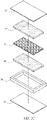
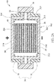
- the above-mentioned battery units 20 are stacked and the metallized plastic film package 30 is utilized to seal the stacked battery units 20 to form the soft pack battery module of this invention, i.e. a quasi-coin battery module.
- the battery units 20 are stacked in the same orientation.
- the current collectors 24 with the same polarity are disposed to face up.
- the lower current collectors 25 will be in direct contact with the current collectors 24 of the adjacent battery units 20 to form a battery cell 40 with series connections. Therefore, the uppermost current collector 24 and the lowermost current collector 25 are the electric power outputs of this battery cell 40.
- Each battery unit 20 has its individual package structure. There only have charges transferred rather than electrochemical reactions occurred between the adjacent battery units 20.
- the two current collectors 24, 25 and the sealing frame 26 serve as the package structure of the battery unit 20.
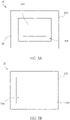
- the metallized plastic film package 30 includes two sheets 31. Please refer to FIGS. 2A , 3A, and 3B , the sheet 31 is composed of a metallized plastic film.
- the metallized plastic film has an inner surface 311 and an outer surface 312.
- the inner surface 311 has an inner electrically-conductive area 313 and an inner electrically insulating area 314.
- the inner electrically insulating area 314 is formed by coating with an inner electrically insulating layer 315 on the inner surface 311, as shown in FIG.2A .
- the outer surface 312 has an outer electrically-conductive area 316 and an outer electrically insulating area.
- the outer electrically insulating area is formed by coating an outer electrically insulating layer 317 on the outer surface 312.
- the inner electrically-conductive area 313 is electrically connected with the outer electrically-conductive area 316.
- the presence of the inner electrically insulating layer 315 can insulate the side surface of the battery cell 40 to avoid contact with the metallized plastic film to cause a short circuit.
- the inner surfaces 311 of the two sheets 31 are disposed opposite each other.
- An adhesive layer 33 is disposed on parts of the inner electrically insulating area 314 of the inner surface 311 to define as an inner adhering area, as shown in FIG.3A .
- the two sheets 31 are adhered to each other and form a space for the battery cell 40 to be disposed.
- the two electric power outputs of the battery cell 40 i.e. the uppermost current collector 24 and the lowermost current collector 25 at both ends, are respectively in direct contact with the inner electrically-conductive areas 313 of the sheets 31 to form the electrical connections. Then the electricity can be transmitted outward through the outer electrically-conductive areas 316 of the outer surfaces 312 of the sheets 31.
- the adhesive layer 33 extends to over almost all the inner electrically insulating area 314 of the inner surface 311, as showing in FIG. 2B . Also, an electrically insulating and moisture barrier layer 34 is disposed on an end surface of the boundary between the two sheets 31 to complete the whole package structure.
- the adhesive layer 33 may be formed on both the sheets 31. Therefore, a two-layered adhesive layer 33 can be achieved. Further, please refer to FIG. 2D , in case of the adhesive layer 33 is electrical insulation, the adhesive layer 33 is disposed on the inner surface 311 to form the inner electrically insulating area 314. The inner electrically insulating layer can be omitted.
- the material of the adhesive layer 33 may be composed of polyethylene or polypropylene. Also, the adhesive layer 33 can be made of the same material as the sealing frame 26 of the battery unit 20. The main functions of the adhesive layer 33 is not only to adhere the two cover sheets 31, but also to offer sufficient electrical insulation and moisture barrier. Furthermore, if it is considered that the adhesive layer 33 has sufficient electrical insulation and moisture barrier, the electrically insulating and moisture barrier layer 34 at the edge can be omitted, see FIG. 2E .
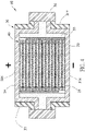
- FIG. 4 is a schematic diagram of the soft pack battery module with connections in parallel.
- the battery units 20 are stacked in different orientations. It means that the current collectors 24, 25 with the same polarity in direct contact to each other.
- the tab or terminal is further utilized to connect the current collectors 24, 25 with the same polarity together to form the battery cell 40 with connections in parallel.
- the package structure or contacting is the same, and will not be repeated here.
- Three battery units 20 are connected in parallel as a group, and the parallel connection is the same as that in the above-mentioned description of FIG. 4 . Then the three parallel groups are connected in series. Similarly, the series connection is the same as that in the above-mentioned description of FIG. 2A . Therefore, both series and parallel connections can be made.
- a fire retardant is filled between the metallized plastic film package 30 and the battery cell 40 to enhance the safety of the battery device.
- the heat dissipating leads are adapted to improve heat dissipation.
- the heat dissipating leads include a positive heat dissipating lead 41 and a negative heat dissipating lead 42.
- the positive heat dissipating lead 41 includes a plate body 411 and a plurality of extension plates 412
- the negative heat dissipating lead 42 includes a plate body 421 and a plurality of extension plates 422.
- the extension plates 412 of the positive heat dissipating lead 41 contact with a surface of the current collectors 24 with positive polarity and the extension plates 422 of the negative heat dissipating lead 42 contact with a surface of the current collectors 25 with negative polarity.
- the battery units 20 of the battery cell 40 are stacked in the same orientation.
- the current collectors 24 of the same polarity are all disposed to face up, and are connected in direct contact with the extension plates 412 of the positive heat dissipating lead 41.
- the current collectors 25 of the other polarity are all facing down and are in direct contact with the extension plates 422 of the negative heat dissipating lead 42 for electrical connections. That is, the extension plates 412 of the positive heat dissipating lead 41 and the extension plates 422 of the negative heat dissipating lead 42 are alternately arranged to form the parallel connection. Therefore, the positive heat dissipating lead 41 and the negative heat dissipating lead 42 are both made of electrically conductive materials.
- an electrically insulating plate 50 can be added therebetween for electrical isolation.
- the large-area contact structure can effectively dissipate the heat generated by the battery cell 40 to maintain the best performance of the battery cell 40.
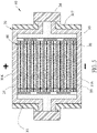
- the soft pack battery module 60 formed by the battery cells 40 encapsulated in the metallized plastic film package 30 can be considered as a battery element.
- a plurality of battery elements are utilized to be connected together in series, in parallel or both, to form an electricity supply with sufficient capacity and voltage.
- the soft pack battery module 60 is disposed between the first electrically insulating layer 71 with a first patterned metal layer 711 and the second electrically insulating layer 72 with a second patterned metal layer 721.
- the second patterned metal layer 721 of the second electrically insulating layer 72 is opposed to the first patterned metal layer 711 of the first electrically insulating layer 71.
- the outer electrically-conductive areas 316 of the soft pack battery module 60 are directly contacted to the first patterned metal layer 711 and the second patterned metal layer 721 to form electrical connections.
- each of the vertical groups include at least one soft pack battery module 60 and the outer electrically-conductive areas 316 of the outermost soft pack battery module 60 of the vertical group are directly contacted to the first patterned metal layer 711 and the second patterned metal layer 721 to form electrical connections in a horizontal direction, i.e. along with the X-axis, parallel to the first electrically insulating layer 711 and the second electrically insulating layer 721.
- the adopted soft pack battery module 60 is not limited to the one shown in FIG. 5 , but can also adopt the soft pack battery module 60 shown in FIG. 2 or 4 , or any other arrangements not shown above.
- the stacking and connection of the soft pack battery module 60 are not only limited to that shown in FIGS. 7A and 7B , but also can be stacked and connected in any directions.
- the arrangements in multi-axis please also see the US20200052341A1 , US20200052000A1 or AU2021101083 for more details.
- the invention provides a soft pack battery module and its electricity supply thereof.
- the battery cell is stacked by the battery units with complete and individual package to connect in series, in parallel or both.
- the metallized plastic film package is utilized to seal the battery cell to form the soft pack battery module.
- the inner electrically-conductive areas of the shells of the metallized plastic film package are used to form electrical connections with the electric power outputs of the battery cell.
- the exposed outer electrically-conductive areas of the shells are used to transmit the electricity. Therefore, the additional transmission structure, such as wires, of the conventional aluminum plastic film battery can be omitted.
- the current path of the battery cell can be maximized.
- the soft pack battery modules are stacked vertically and the outer electrically-conductive areas can be used to form electrical connections therebetween directly, without the need for additional wires. Therefore, it can improve the efficiency of the assembling process. And it is easy to replace when a single soft pack battery module is failed.
Landscapes
- Chemical & Material Sciences (AREA)
- Chemical Kinetics & Catalysis (AREA)
- Electrochemistry (AREA)
- General Chemical & Material Sciences (AREA)
- Engineering & Computer Science (AREA)
- Inorganic Chemistry (AREA)
- Manufacturing & Machinery (AREA)
- Ceramic Engineering (AREA)
- Composite Materials (AREA)
- Materials Engineering (AREA)
- Battery Mounting, Suspending (AREA)
- Connection Of Batteries Or Terminals (AREA)
- Sealing Battery Cases Or Jackets (AREA)
- Secondary Cells (AREA)
- Charge And Discharge Circuits For Batteries Or The Like (AREA)
- Cell Separators (AREA)
Applications Claiming Priority (1)
| Application Number | Priority Date | Filing Date | Title |
|---|---|---|---|
| TW110109697A TWI762244B (zh) | 2021-03-18 | 2021-03-18 | 軟包式電池模組及其電能供應器 |
Publications (4)
| Publication Number | Publication Date |
|---|---|
| EP4060795A2 true EP4060795A2 (de) | 2022-09-21 |
| EP4060795A3 EP4060795A3 (de) | 2022-09-28 |
| EP4060795C0 EP4060795C0 (de) | 2025-10-15 |
| EP4060795B1 EP4060795B1 (de) | 2025-10-15 |
Family
ID=80447269
Family Applications (1)
| Application Number | Title | Priority Date | Filing Date |
|---|---|---|---|
| EP22157908.9A Active EP4060795B1 (de) | 2021-03-18 | 2022-02-22 | Softpack-batteriemodul und dessen stromversorgung |
Country Status (6)
| Country | Link |
|---|---|
| US (1) | US12322834B2 (de) |
| EP (1) | EP4060795B1 (de) |
| JP (2) | JP2022145534A (de) |
| KR (1) | KR102939630B1 (de) |
| AU (1) | AU2022200882B2 (de) |
| TW (1) | TWI762244B (de) |
Citations (5)
| Publication number | Priority date | Publication date | Assignee | Title |
|---|---|---|---|---|
| CN109860445A (zh) | 2019-01-10 | 2019-06-07 | 金能电池(东莞)有限公司 | 一种新型的铝塑膜纽扣电池 |
| CN110416442A (zh) | 2019-06-19 | 2019-11-05 | 金能电池(东莞)有限公司 | 一种多极耳铝塑膜电池 |
| US20200052000A1 (en) | 2018-08-08 | 2020-02-13 | Prologium Technology Co., Ltd. | Horizontal composite electricity supply structure |
| US20200052341A1 (en) | 2018-08-08 | 2020-02-13 | Prologium Technology Co., Ltd. | Horizontal composite electricity supply element group |
| AU2021101083A4 (en) | 2020-03-23 | 2021-04-29 | Prologium Holding Inc | Multiaxial Electricity Supply System |
Family Cites Families (17)
| Publication number | Priority date | Publication date | Assignee | Title |
|---|---|---|---|---|
| US5478667A (en) * | 1992-10-29 | 1995-12-26 | Shackle; Dale R. | Heat dissipating current collector for a battery |
| JP2003331819A (ja) | 2002-05-14 | 2003-11-21 | Toyota Motor Corp | 二次電池 |
| JP2005276486A (ja) | 2004-03-23 | 2005-10-06 | Nissan Motor Co Ltd | 積層型電池、組電池および車両 |
| KR100857034B1 (ko) | 2005-03-25 | 2008-09-05 | 주식회사 엘지화학 | 난연성 접착부재를 포함하고 있는 전지 |
| JP5017843B2 (ja) | 2005-10-26 | 2012-09-05 | 日産自動車株式会社 | 電池モジュール、および組電池 |
| JP2008159328A (ja) | 2006-12-21 | 2008-07-10 | Nissan Motor Co Ltd | 電池モジュール |
| CN103682191B (zh) | 2012-09-06 | 2016-08-24 | 阿提瓦公司 | 框架具有点胶挡止的电池组件 |
| US10211443B2 (en) | 2014-09-10 | 2019-02-19 | Cellink Corporation | Battery interconnects |
| JP6582443B2 (ja) * | 2015-02-27 | 2019-10-02 | 三洋電機株式会社 | 二次電池及びその製造方法 |
| JP6663685B2 (ja) | 2015-11-04 | 2020-03-13 | 日本特殊陶業株式会社 | リチウムイオン伝導性セラミックス焼結体、及びリチウム電池 |
| JP2018098167A (ja) * | 2016-12-14 | 2018-06-21 | 昭和電工株式会社 | リチウムイオン二次電池、リチウムイオン二次電池の電池構造、リチウムイオン二次電池の製造方法 |
| AU2018202147A1 (en) | 2017-04-19 | 2018-11-29 | Johnson & Johnson Vision Care, Inc. | Flexible micro-battery |
| TWI676315B (zh) * | 2017-10-20 | 2019-11-01 | 輝能科技股份有限公司 | 複合式電池芯 |
| US20220021046A1 (en) * | 2018-07-30 | 2022-01-20 | Cadenza Innovation, Inc. | Housing for Rechargeable Batteries |
| EP3926717A4 (de) * | 2019-03-20 | 2022-04-27 | APB Corporation | Lithiumionenbatterie und verfahren zur beurteilung der verschlechterung einer lithiumionenbatterie |
| JP7475825B2 (ja) | 2019-08-19 | 2024-04-30 | Apb株式会社 | リチウムイオン電池モジュール及び電池パック |
| US20220336818A1 (en) * | 2019-08-19 | 2022-10-20 | Apb Corporation | Lithium ion battery module and battery pack |
-
2021
- 2021-03-18 TW TW110109697A patent/TWI762244B/zh active
-
2022
- 2022-02-09 US US17/667,820 patent/US12322834B2/en active Active
- 2022-02-10 AU AU2022200882A patent/AU2022200882B2/en active Active
- 2022-02-17 JP JP2022022935A patent/JP2022145534A/ja active Pending
- 2022-02-22 EP EP22157908.9A patent/EP4060795B1/de active Active
- 2022-02-28 KR KR1020220026181A patent/KR102939630B1/ko active Active
-
2024
- 2024-03-05 JP JP2024000661U patent/JP3246636U/ja active Active
Patent Citations (5)
| Publication number | Priority date | Publication date | Assignee | Title |
|---|---|---|---|---|
| US20200052000A1 (en) | 2018-08-08 | 2020-02-13 | Prologium Technology Co., Ltd. | Horizontal composite electricity supply structure |
| US20200052341A1 (en) | 2018-08-08 | 2020-02-13 | Prologium Technology Co., Ltd. | Horizontal composite electricity supply element group |
| CN109860445A (zh) | 2019-01-10 | 2019-06-07 | 金能电池(东莞)有限公司 | 一种新型的铝塑膜纽扣电池 |
| CN110416442A (zh) | 2019-06-19 | 2019-11-05 | 金能电池(东莞)有限公司 | 一种多极耳铝塑膜电池 |
| AU2021101083A4 (en) | 2020-03-23 | 2021-04-29 | Prologium Holding Inc | Multiaxial Electricity Supply System |
Also Published As
| Publication number | Publication date |
|---|---|
| TW202239051A (zh) | 2022-10-01 |
| US12322834B2 (en) | 2025-06-03 |
| US20220302557A1 (en) | 2022-09-22 |
| EP4060795C0 (de) | 2025-10-15 |
| EP4060795B1 (de) | 2025-10-15 |
| KR20220130587A (ko) | 2022-09-27 |
| JP3246636U (ja) | 2024-05-13 |
| EP4060795A3 (de) | 2022-09-28 |
| JP2022145534A (ja) | 2022-10-04 |
| AU2022200882A1 (en) | 2022-10-06 |
| KR102939630B1 (ko) | 2026-03-13 |
| TWI762244B (zh) | 2022-04-21 |
| AU2022200882B2 (en) | 2023-12-14 |
Similar Documents
| Publication | Publication Date | Title |
|---|---|---|
| US12407021B2 (en) | Composite battery cell | |
| KR102351994B1 (ko) | 수평 복합 전기 공급 요소 그룹 | |
| EP4075555B1 (de) | Elektrodenanordnung und batterievorrichtung dafür | |
| TWM615887U (zh) | 類鈕扣電池模組及其電池裝置 | |
| US11978873B2 (en) | Battery module with cooling cartridge and battery system thereof | |
| US12322834B2 (en) | Soft pack battery module and its electricity supply thereof | |
| CN115117522B (zh) | 软包式电池模块及其电能供应器 | |
| KR200499830Y1 (ko) | 독립적인 모니터링 기능을 갖는 금속 하우징형 배터리 장치 | |
| CN214848765U (zh) | 具有独立监控的金属壳式电池装置 | |
| JP3250421U (ja) | 側面に放熱接着剤、構造用接着剤を有するバッテリ | |
| CN214754060U (zh) | 类钮扣电池模块及其电池装置 | |
| CN115117497A (zh) | 具散热匣体的电池模块及其电池系统 |
Legal Events
| Date | Code | Title | Description |
|---|---|---|---|
| PUAI | Public reference made under article 153(3) epc to a published international application that has entered the european phase |
Free format text: ORIGINAL CODE: 0009012 |
|
| STAA | Information on the status of an ep patent application or granted ep patent |
Free format text: STATUS: THE APPLICATION HAS BEEN PUBLISHED |
|
| PUAL | Search report despatched |
Free format text: ORIGINAL CODE: 0009013 |
|
| AK | Designated contracting states |
Kind code of ref document: A2 Designated state(s): AL AT BE BG CH CY CZ DE DK EE ES FI FR GB GR HR HU IE IS IT LI LT LU LV MC MK MT NL NO PL PT RO RS SE SI SK SM TR |
|
| AK | Designated contracting states |
Kind code of ref document: A3 Designated state(s): AL AT BE BG CH CY CZ DE DK EE ES FI FR GB GR HR HU IE IS IT LI LT LU LV MC MK MT NL NO PL PT RO RS SE SI SK SM TR |
|
| RIC1 | Information provided on ipc code assigned before grant |
Ipc: H01M 50/176 20210101ALI20220819BHEP Ipc: H01M 50/209 20210101ALI20220819BHEP Ipc: H01M 50/20 20210101ALI20220819BHEP Ipc: H01M 50/126 20210101ALI20220819BHEP Ipc: H01M 50/124 20210101ALI20220819BHEP Ipc: H01M 50/122 20210101ALI20220819BHEP Ipc: H01M 50/121 20210101ALI20220819BHEP Ipc: H01M 50/119 20210101ALI20220819BHEP Ipc: H01M 50/105 20210101AFI20220819BHEP |
|
| STAA | Information on the status of an ep patent application or granted ep patent |
Free format text: STATUS: REQUEST FOR EXAMINATION WAS MADE |
|
| 17P | Request for examination filed |
Effective date: 20230324 |
|
| RBV | Designated contracting states (corrected) |
Designated state(s): AL AT BE BG CH CY CZ DE DK EE ES FI FR GB GR HR HU IE IS IT LI LT LU LV MC MK MT NL NO PL PT RO RS SE SI SK SM TR |
|
| GRAP | Despatch of communication of intention to grant a patent |
Free format text: ORIGINAL CODE: EPIDOSNIGR1 |
|
| STAA | Information on the status of an ep patent application or granted ep patent |
Free format text: STATUS: GRANT OF PATENT IS INTENDED |
|
| INTG | Intention to grant announced |
Effective date: 20250506 |
|
| GRAS | Grant fee paid |
Free format text: ORIGINAL CODE: EPIDOSNIGR3 |
|
| GRAA | (expected) grant |
Free format text: ORIGINAL CODE: 0009210 |
|
| STAA | Information on the status of an ep patent application or granted ep patent |
Free format text: STATUS: THE PATENT HAS BEEN GRANTED |
|
| AK | Designated contracting states |
Kind code of ref document: B1 Designated state(s): AL AT BE BG CH CY CZ DE DK EE ES FI FR GB GR HR HU IE IS IT LI LT LU LV MC MK MT NL NO PL PT RO RS SE SI SK SM TR |
|
| REG | Reference to a national code |
Ref country code: GB Ref legal event code: FG4D Ref country code: CH Ref legal event code: F10 Free format text: ST27 STATUS EVENT CODE: U-0-0-F10-F00 (AS PROVIDED BY THE NATIONAL OFFICE) Effective date: 20251015 |
|
| REG | Reference to a national code |
Ref country code: DE Ref legal event code: R096 Ref document number: 602022022901 Country of ref document: DE |
|
| REG | Reference to a national code |
Ref country code: IE Ref legal event code: FG4D |
|
| U01 | Request for unitary effect filed |
Effective date: 20251023 |
|
| U07 | Unitary effect registered |
Designated state(s): AT BE BG DE DK EE FI FR IT LT LU LV MT NL PT RO SE SI Effective date: 20251030 |
|
| U20 | Renewal fee for the european patent with unitary effect paid |
Year of fee payment: 5 Effective date: 20260227 |
|
| PGFP | Annual fee paid to national office [announced via postgrant information from national office to epo] |
Ref country code: GB Payment date: 20260204 Year of fee payment: 5 |
|
| PG25 | Lapsed in a contracting state [announced via postgrant information from national office to epo] |
Ref country code: ES Free format text: LAPSE BECAUSE OF FAILURE TO SUBMIT A TRANSLATION OF THE DESCRIPTION OR TO PAY THE FEE WITHIN THE PRESCRIBED TIME-LIMIT Effective date: 20251015 |
|
| PG25 | Lapsed in a contracting state [announced via postgrant information from national office to epo] |
Ref country code: NO Free format text: LAPSE BECAUSE OF FAILURE TO SUBMIT A TRANSLATION OF THE DESCRIPTION OR TO PAY THE FEE WITHIN THE PRESCRIBED TIME-LIMIT Effective date: 20260115 |
|
| PG25 | Lapsed in a contracting state [announced via postgrant information from national office to epo] |
Ref country code: HR Free format text: LAPSE BECAUSE OF FAILURE TO SUBMIT A TRANSLATION OF THE DESCRIPTION OR TO PAY THE FEE WITHIN THE PRESCRIBED TIME-LIMIT Effective date: 20251015 |
|
| PG25 | Lapsed in a contracting state [announced via postgrant information from national office to epo] |
Ref country code: RS Free format text: LAPSE BECAUSE OF FAILURE TO SUBMIT A TRANSLATION OF THE DESCRIPTION OR TO PAY THE FEE WITHIN THE PRESCRIBED TIME-LIMIT Effective date: 20260115 |
|
| PG25 | Lapsed in a contracting state [announced via postgrant information from national office to epo] |
Ref country code: IS Free format text: LAPSE BECAUSE OF FAILURE TO SUBMIT A TRANSLATION OF THE DESCRIPTION OR TO PAY THE FEE WITHIN THE PRESCRIBED TIME-LIMIT Effective date: 20260215 |
|
| PG25 | Lapsed in a contracting state [announced via postgrant information from national office to epo] |
Ref country code: PL Free format text: LAPSE BECAUSE OF FAILURE TO SUBMIT A TRANSLATION OF THE DESCRIPTION OR TO PAY THE FEE WITHIN THE PRESCRIBED TIME-LIMIT Effective date: 20251015 |