EP4060073A1 - Bearing wire rod and manufacturing method therefor - Google Patents
Bearing wire rod and manufacturing method therefor Download PDFInfo
- Publication number
- EP4060073A1 EP4060073A1 EP20903915.5A EP20903915A EP4060073A1 EP 4060073 A1 EP4060073 A1 EP 4060073A1 EP 20903915 A EP20903915 A EP 20903915A EP 4060073 A1 EP4060073 A1 EP 4060073A1
- Authority
- EP
- European Patent Office
- Prior art keywords
- wire rod
- less
- heat treatment
- present disclosure
- grain boundaries
- Prior art date
- Legal status (The legal status is an assumption and is not a legal conclusion. Google has not performed a legal analysis and makes no representation as to the accuracy of the status listed.)
- Pending
Links
Images



Classifications
-
- C—CHEMISTRY; METALLURGY
- C21—METALLURGY OF IRON
- C21D—MODIFYING THE PHYSICAL STRUCTURE OF FERROUS METALS; GENERAL DEVICES FOR HEAT TREATMENT OF FERROUS OR NON-FERROUS METALS OR ALLOYS; MAKING METAL MALLEABLE, e.g. BY DECARBURISATION OR TEMPERING
- C21D8/00—Modifying the physical properties of ferrous metals or ferrous alloys by deformation combined with, or followed by, heat treatment
- C21D8/06—Modifying the physical properties of ferrous metals or ferrous alloys by deformation combined with, or followed by, heat treatment during manufacturing of rods or wires
-
- C—CHEMISTRY; METALLURGY
- C22—METALLURGY; FERROUS OR NON-FERROUS ALLOYS; TREATMENT OF ALLOYS OR NON-FERROUS METALS
- C22C—ALLOYS
- C22C38/00—Ferrous alloys, e.g. steel alloys
- C22C38/18—Ferrous alloys, e.g. steel alloys containing chromium
- C22C38/26—Ferrous alloys, e.g. steel alloys containing chromium with niobium or tantalum
-
- B—PERFORMING OPERATIONS; TRANSPORTING
- B21—MECHANICAL METAL-WORKING WITHOUT ESSENTIALLY REMOVING MATERIAL; PUNCHING METAL
- B21B—ROLLING OF METAL
- B21B1/00—Metal-rolling methods or mills for making semi-finished products of solid or profiled cross-section; Sequence of operations in milling trains; Layout of rolling-mill plant, e.g. grouping of stands; Succession of passes or of sectional pass alternations
- B21B1/16—Metal-rolling methods or mills for making semi-finished products of solid or profiled cross-section; Sequence of operations in milling trains; Layout of rolling-mill plant, e.g. grouping of stands; Succession of passes or of sectional pass alternations for rolling wire rods, bars, merchant bars, rounds wire or material of like small cross-section
-
- B—PERFORMING OPERATIONS; TRANSPORTING
- B21—MECHANICAL METAL-WORKING WITHOUT ESSENTIALLY REMOVING MATERIAL; PUNCHING METAL
- B21B—ROLLING OF METAL
- B21B3/00—Rolling materials of special alloys so far as the composition of the alloy requires or permits special rolling methods or sequences ; Rolling of aluminium, copper, zinc or other non-ferrous metals
-
- C—CHEMISTRY; METALLURGY
- C21—METALLURGY OF IRON
- C21D—MODIFYING THE PHYSICAL STRUCTURE OF FERROUS METALS; GENERAL DEVICES FOR HEAT TREATMENT OF FERROUS OR NON-FERROUS METALS OR ALLOYS; MAKING METAL MALLEABLE, e.g. BY DECARBURISATION OR TEMPERING
- C21D1/00—General methods or devices for heat treatment, e.g. annealing, hardening, quenching or tempering
- C21D1/18—Hardening; Quenching with or without subsequent tempering
-
- C—CHEMISTRY; METALLURGY
- C21—METALLURGY OF IRON
- C21D—MODIFYING THE PHYSICAL STRUCTURE OF FERROUS METALS; GENERAL DEVICES FOR HEAT TREATMENT OF FERROUS OR NON-FERROUS METALS OR ALLOYS; MAKING METAL MALLEABLE, e.g. BY DECARBURISATION OR TEMPERING
- C21D1/00—General methods or devices for heat treatment, e.g. annealing, hardening, quenching or tempering
- C21D1/26—Methods of annealing
-
- C—CHEMISTRY; METALLURGY
- C21—METALLURGY OF IRON
- C21D—MODIFYING THE PHYSICAL STRUCTURE OF FERROUS METALS; GENERAL DEVICES FOR HEAT TREATMENT OF FERROUS OR NON-FERROUS METALS OR ALLOYS; MAKING METAL MALLEABLE, e.g. BY DECARBURISATION OR TEMPERING
- C21D1/00—General methods or devices for heat treatment, e.g. annealing, hardening, quenching or tempering
- C21D1/26—Methods of annealing
- C21D1/32—Soft annealing, e.g. spheroidising
-
- C—CHEMISTRY; METALLURGY
- C21—METALLURGY OF IRON
- C21D—MODIFYING THE PHYSICAL STRUCTURE OF FERROUS METALS; GENERAL DEVICES FOR HEAT TREATMENT OF FERROUS OR NON-FERROUS METALS OR ALLOYS; MAKING METAL MALLEABLE, e.g. BY DECARBURISATION OR TEMPERING
- C21D6/00—Heat treatment of ferrous alloys
- C21D6/002—Heat treatment of ferrous alloys containing Cr
-
- C—CHEMISTRY; METALLURGY
- C21—METALLURGY OF IRON
- C21D—MODIFYING THE PHYSICAL STRUCTURE OF FERROUS METALS; GENERAL DEVICES FOR HEAT TREATMENT OF FERROUS OR NON-FERROUS METALS OR ALLOYS; MAKING METAL MALLEABLE, e.g. BY DECARBURISATION OR TEMPERING
- C21D9/00—Heat treatment, e.g. annealing, hardening, quenching or tempering, adapted for particular articles; Furnaces therefor
- C21D9/52—Heat treatment, e.g. annealing, hardening, quenching or tempering, adapted for particular articles; Furnaces therefor for wires; for strips ; for rods of unlimited length
- C21D9/525—Heat treatment, e.g. annealing, hardening, quenching or tempering, adapted for particular articles; Furnaces therefor for wires; for strips ; for rods of unlimited length for wire, for rods
-
- C—CHEMISTRY; METALLURGY
- C22—METALLURGY; FERROUS OR NON-FERROUS ALLOYS; TREATMENT OF ALLOYS OR NON-FERROUS METALS
- C22C—ALLOYS
- C22C38/00—Ferrous alloys, e.g. steel alloys
- C22C38/001—Ferrous alloys, e.g. steel alloys containing N
-
- C—CHEMISTRY; METALLURGY
- C22—METALLURGY; FERROUS OR NON-FERROUS ALLOYS; TREATMENT OF ALLOYS OR NON-FERROUS METALS
- C22C—ALLOYS
- C22C38/00—Ferrous alloys, e.g. steel alloys
- C22C38/02—Ferrous alloys, e.g. steel alloys containing silicon
-
- C—CHEMISTRY; METALLURGY
- C22—METALLURGY; FERROUS OR NON-FERROUS ALLOYS; TREATMENT OF ALLOYS OR NON-FERROUS METALS
- C22C—ALLOYS
- C22C38/00—Ferrous alloys, e.g. steel alloys
- C22C38/04—Ferrous alloys, e.g. steel alloys containing manganese
-
- C—CHEMISTRY; METALLURGY
- C22—METALLURGY; FERROUS OR NON-FERROUS ALLOYS; TREATMENT OF ALLOYS OR NON-FERROUS METALS
- C22C—ALLOYS
- C22C38/00—Ferrous alloys, e.g. steel alloys
- C22C38/06—Ferrous alloys, e.g. steel alloys containing aluminium
-
- C—CHEMISTRY; METALLURGY
- C22—METALLURGY; FERROUS OR NON-FERROUS ALLOYS; TREATMENT OF ALLOYS OR NON-FERROUS METALS
- C22C—ALLOYS
- C22C38/00—Ferrous alloys, e.g. steel alloys
- C22C38/18—Ferrous alloys, e.g. steel alloys containing chromium
-
- C—CHEMISTRY; METALLURGY
- C21—METALLURGY OF IRON
- C21D—MODIFYING THE PHYSICAL STRUCTURE OF FERROUS METALS; GENERAL DEVICES FOR HEAT TREATMENT OF FERROUS OR NON-FERROUS METALS OR ALLOYS; MAKING METAL MALLEABLE, e.g. BY DECARBURISATION OR TEMPERING
- C21D2211/00—Microstructure comprising significant phases
- C21D2211/001—Austenite
-
- C—CHEMISTRY; METALLURGY
- C21—METALLURGY OF IRON
- C21D—MODIFYING THE PHYSICAL STRUCTURE OF FERROUS METALS; GENERAL DEVICES FOR HEAT TREATMENT OF FERROUS OR NON-FERROUS METALS OR ALLOYS; MAKING METAL MALLEABLE, e.g. BY DECARBURISATION OR TEMPERING
- C21D2211/00—Microstructure comprising significant phases
- C21D2211/003—Cementite
-
- C—CHEMISTRY; METALLURGY
- C21—METALLURGY OF IRON
- C21D—MODIFYING THE PHYSICAL STRUCTURE OF FERROUS METALS; GENERAL DEVICES FOR HEAT TREATMENT OF FERROUS OR NON-FERROUS METALS OR ALLOYS; MAKING METAL MALLEABLE, e.g. BY DECARBURISATION OR TEMPERING
- C21D2211/00—Microstructure comprising significant phases
- C21D2211/009—Pearlite
Definitions
- the present disclosure relates to a bearing wire rod and a manufacturing method therefor, and more particularly, to a bearing wire rod applicable to automotive and construction parts by shortening and omitting a subsequent softening heat treatment and a manufacturing method therefor.
- Spheroidizing heat treatment spheroidizes cementite and induces uniform distribution of grains to enhance cold workability during cold forming.
- hardness of a material being processed may be lowered to increase the lifespan of processing dies thereby.
- CHQ cold heading quality
- softening heat treatment is conducted at least once. Subsequently, drawing and heat treatment processes are additional performed in order to improve cold forgeability, and cold forgeability may be obtained by tensile strength and spheroidal ratio after the softening heat treatment.
- a bearing wire rod manufactured by shortening or omitting a softening heat treatment during cold working of automotive or construction parts and a manufacturing method therefor.
- a bearing wire rod includes, in percent by weight (wt%), 0.8 to 1.2% of C, 0.01 to 0.6% of Si, 0.1 to 0.6% of Mn, 1.0 to 2.0% of Cr, 0.01 to 0.06% of Al, 0.02% or less (exclusive of 0) of N, and the balance of Fe and inevitable impurities, wherein a prior austenite grain size of a microstructure is from 3 to 10 ⁇ m, and a sum of lengths of high angle grain boundaries having a misorientation angle of 15° or more per unit area is from 1,000 to 4,000 mm/mm 2 .
- a sum of lengths of low angle grain boundaries having a misorientation angle of 15° or less per unit area may be from 250 to 800 mm/mm 2
- a ratio of grain boundaries having a misorientation angle of 5° or less to the low angle grain boundaries may be from 40 to 80%.
- the microstructure may include reticulated proeutectoid cementite in grain boundaries and pearlite in grains.
- an interlamellar spacing in the pearlite may be from 0.05 to 0.2 ⁇ m.
- a tensile strength may be 1,200 MPa or more and a reduction in area (RA) may be 20% or more.
- an average aspect ratio of cementite may be 2.5 or less after performing softening heat treatment once.
- a tensile strength may be 750 MPa or less after performing softening heat treatment once.
- the wire rod may satisfy Expression (2) below.
- T pf is an average surface temperature of the wire rod before the finish hot rolling
- T f is an average surface temperature of the wire rod after the finish hot rolling.
- a heating time may be 90 minutes or less.
- an average austenite grain size (AGS) before the finish hot rolling may be from 5 to 20 ⁇ m.
- the method may further include performing softening heat treatment by heating the wire rod to a temperature range of Ae1 to Ae1+40 °C after the cooling and maintaining the temperature for 5 to 8 hours.
- the method may further include cooling the wire rod to 660 °C at a rate of 20 °C/hr or less after the softening heat treatment.
- the softening heat treatment time may be shortened or the softening heat treatment may be omitted, and therefore manufacturing costs may be reduced.
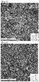
- FIGS. 1 and 2 are images of microstructures of wire rods prepared according to Example 1 of the present disclosure and Comparative Example 1 obtained before finish hot rolling using an optical microscope (OM).
- FIGS. 3 and 4 are images of microstructures of wire rods prepared according to Example 1 of the present disclosure and Comparative Example 1 obtained after finish hot rolling and cooling using a scanning electron microscope (SEM).
- SEM scanning electron microscope
- FIGS. 5 and 6 are images of wire rods prepared according to Example 1 of the present disclosure and Comparative Example 1 showing grain boundary characteristics after finish hot rolling and cooling observed by SEM-EBSD.
- FIGS. 7 and 8 are images of microstructures of wire rods prepared according to Example 1 of the present disclosure and Comparative Example 1 obtained after spheroidizing heat treatment using a scanning electron microscope (SEM).
- SEM scanning electron microscope
- a bearing wire rod including, in percent by weight (wt%), 0.8 to 1.2% of C, 0.01 to 0.6% of Si, 0.1 to 0.6% of Mn, 1.0 to 2.0% of Cr, 0.01 to 0.06% of Al, 0.02% or less (exclusive of 0) of N, and the balance of Fe and inevitable impurities, wherein a prior austenite grain size of a microstructure is from 3 to 10 ⁇ m, and a sum of lengths of high angle grain boundaries having a misorientation angle of 15° or more per unit area is from 1,000 to 4,000 mm/mm 2 .
- Spheroidizing heat treatment may be performed on wire rods for bearing to obtain workability. Because the spheroidizing heat treatment is an additional process, heat treatment costs and time increase, resulting in an increase in manufacturing costs.
- the present inventors have conducted deep studies on methods of shortening or omitting spheroidizing, softening heat treatment in preparation of wire rods for bearings. As a result, the present inventors have confirmed that softening heat treatment may be shortened or omitted by deriving desired characteristics of grains boundaries by optimizing a composition of alloying elements and manufacturing conditions, thereby completing the present disclosure.
- a bearing wire rod includes, in percent by weight (wt%), 0.8 to 1.2% of C, 0.01 to 0.6% of Si, 0.1 to 0.6% of Mn, 1.0 to 2.0% of Cr, 0.01 to 0.06% of Al, 0.02% or less (exclusive of 0) of N, and the balance of Fe and inevitable impurities.
- the % for each alloying element refers to wt %.
- the content of C is from 0.8 to 1.2%.
- Carbon (C) is an element added to obtain strength of products.
- the C content is less than 0.8%, sufficient strength cannot be obtained after quenching and tempering heat treatment performed after softening heat treatment and forging process due to a decrease in strength of a base material.
- an excess of C may form new precipitates such as M 7 C 3 , and thus central segregation may occur during solidification of slabs such as blooms or billets. Therefore, an upper limit of the C content may be controlled to 1.2%.
- the C content may be from 0.8 to 1.1%.
- the content of Si is from 0.01 to 0.6%.
- Si Silicon
- Si as a representative substitutional element, is advantageous to obtain strength by solid solution strengthening.
- Si content is less than 0.01%, it is difficult to obtain strength and sufficient quenchability of a wire rod.
- an excess of Si may increase strength during forging after softening heat treatment making it difficult to obtain cold forgeability. Therefore, an upper limit of the Si content may be controlled to 0.6%.
- the content of Mn is from 0.1 to 0.6%.
- Manganese (Mn) as an element forming a substitutional solid solution in a matrix structure to enhance sold solution strengthening, is an austenite-forming element and added to obtain desired strength without reduction in ductility.
- Mn content is less than 0.1%, it is difficult to obtain strength and toughness due to solid solution strengthening of a wire rod.
- an upper limit of the Mn content may be controlled to 0.6%.
- the content of Cr is from 1.0 to 2.0%.
- Chromium is an element advantageous to obtain a martensite structure by improving quenchability of a wire rod.
- Cr content is less than 1.0%, it is difficult to obtain a martensite microstructure by quenching and tempering heat treatment performed after the softening heat treatment and forging process.
- an upper limit of the Cr content may be controlled to 2.0%.
- the content of Al is from 0.01 to 0.06%.
- Aluminum (Al) is added in an amount of 0.01% or more not only to obtain deoxidization effect, but also inhibit the growth of austenite grains by precipitating an Al-based carbonitride and obtain a fraction of proeutectoid ferrite to be close to an equilibrium phase.
- Al content is excessive, formation of hard inclusions such as Al 2 O 3 increases, and particularly nozzle clogging may occur during casting. Therefore, an upper limit of the Al content may be controlled to 0.06%.
- the content of N is 0.02% or less (exclusive of 0).
- N nitrogen
- an excess of N may deteriorate toughness and ductility of a material due to solute nitrogen not forming a nitride.
- N is controlled as an impurity in the present disclosure, and an upper limit of the N content may be controlled to 0.02%.
- the remaining component of the composition of the present disclosure is iron (Fe).
- the composition may include unintended impurities inevitably incorporated from raw materials or surrounding environments, and thus addition of other alloy components is not excluded.
- Examples of the inevitable impurities may include phosphorus (P) and sulfur (S). These impurities are known to any person skilled in the art of manufacturing and details thereof are not specifically mentioned in the present disclosure.
- reticulated proeutectoid cementite is present in grain boundaries along grains of prior austenite and pearlite is present in the grains.
- the microstructure may have a prior austenite grain size of 3 to 10 ⁇ m.
- the cementite in the pearlite structure is changed from a plate shape to a spherical shape and strength of the wire rod decreases in accordance with a progression degree of spheroidization.
- metal atoms migrate in various diffusion paths through defect space in a material.
- the metal atoms are diffused via vacancies that are atomic defects and via dislocation or pipe and grain boundaries which are line defects.
- High-speed diffusion is possible via dislocation and grain boundaries due to relatively wider spaces compared to atomic defects.
- a heat treatment time is determined by a diffusion rate of each atom, and the most important factor of the diffusion rate is grain boundaries.
- grain boundaries of a grain boundary structure are classified into high angle grain boundaries and low angle grain boundaries based on misorientation between grain boundaries and attempts are made to control distribution of each of the grain boundaries.
- a relation with neighboring grains was quantified as a misorientation angle value, and the grain boundaries were divided, based on the angle 15°, into high angle grain boundaries having an angle of 15° or more and low angle grain boundaries having an angle of 15° or less.
- the distribution of the grain boundaries defined in the present disclosure is applied to the entire area of the wire rod from the surface area to the central area.
- a prior austenite grain size (AGS) of the bearing wire rod is from 3 to 10 ⁇ m
- a sum of lengths of high angle grain boundaries having a misorientation angle of 15° or more per unit area is from 1,000 to 4,000 mm/mm 2 .
- the low angle grain boundaries having a misorientation angle of 15° or less distributed in the high angle grain boundaries may assist a spheroidization behavior during softening heat treatment to improve cold forgeability.
- a sum of the lengths of the low angle grain boundaries having a misorientation angle of 15° or less per unit area is from 250 to 800 mm/mm 2 .
- the effect on shortening the softening heat treatment time is insignificant.
- the length distribution of the low angle grain boundary is greater than 800 mm/mm 2 , dislocation density increases during rolling and thus recrystallization partially occurs to decrease dislocation density or the grains may develop into a bimodal form of different sizes without having a uniform grain size.
- a smaller misorientation angle indicates a larger dislocation.
- a ratio of grain boundaries having a misorientation angle of 5° or less to the low angle grain boundary is from 40 to 80%.
- the wire rod of the present disclosure may be manufactured by preparing a billet having the above-described composition of alloying elements, and performing a process of reheating-wire rod rolling-multi-stage cooling.
- a method for manufacturing a bearing wire rod includes heating a billet including, in percent by weight (wt%), 0.8 to 1.2% of C, 0.01 to 0.6% of Si, 0.1 to 0.6% of Mn, 1.0 to 2.0% of Cr, 0.01 to 0.06% of Al, 0.02% or less (exclusive of 0) of N, and the balance of Fe and inevitable impurities, in a temperature range of 950 to 1,050 °C; preparing a wire rod by finish hot rolling the billet in a temperature range of Ae1 to Acm °C with a critical deformation, represented by Expression (1) below, or more; and cooling the wire rod to a temperature range of 500 to 600 °C at a rate of 3 °C/sec or more and cooling the wire rod at a rate of 1 °C/sec or less.
- Ceq C + Mn/6 + Cr/5, and C, Mn, and Cr denote wt% of respective elements.
- a step of heating the billet having the above-described composition in the temperature range of 950 to 1,050 °C is performed.
- the heating may be performed for 90 minutes or less.
- a depth of a decarburized layer increases on the surface of the wire rod, and thus the decarburized layer remains after the rolling process is completed.
- the heated billet is subjected to hot rolling sequentially consisting of rough rolling, intermediate rough rolling/finish rolling, and finish rolling to prepare a wire rod.
- the hot rolling may be groove rolling to process the billet into the shape of the wire rod, specifically, the billet is subjected to finish hot rolling with a deformation of not less than a critical deformation represented by Expression (1) below in the temperature range of Ae1 to Acm °C to prepare the wire rod.
- the preparation of the wire rod corresponds to a dynamic recrystallization region due to a high rolling speed.
- the austenite grain size (AGS) depends only on a deformation rate and a deformation temperature.
- an interpassing time between two rolls is controlled within 1 minute to obtain an austenite grain size (AGS) of 5 to 20 ⁇ m immediately before the finish rolling, and then the finish rolling temperature may be controlled in the temperature range of Ae1 to Acm °C during the finish rolling.
- AGS austenite grain size
- the deformation of the hot rolling in the above-described temperature range may be controlled to be not less than critical deformation represented by Expression (1) below. ⁇ 1.6 Ceq 2 + 3.11 Ceq ⁇ 0.48
- Ceq C + Mn/6 + Cr/5, and C, Mn, and Cr denote wt% of respective elements.
- the present inventors have derived critical deformation represented by Expression (1) in consideration of relationship between Ceq and deformation.
- Deformation is defined as -ln(1-RA).
- RA is a reduction (RA ⁇ 1) by rolling pass.
- T pf is an average surface temperature of the wire rod before the finish hot rolling
- T f is an average surface temperature of the wire rod after the finish hot rolling
- the wire rod After the hot rolling in the above-described temperature range, the wire rod is cooled to a temperature range of 500 to 600 °C at a rate of 3 °C/sec or more and cooled at a rate of 1 °C/sec or less, thereby obtaining the bearing wire rod according to the present disclosure.
- the above-described cooling step is a process necessary to obtain distribution of fine grains. According to the present disclosure, attempts have been made to obtain a microstructure manufactured by shortening the heat treatment via diffusion acceleration by adjusting a cooling termination temperature and a cooling rate.
- the cooling rate to the temperature range of 500 to 600 °C is less than 3 °C/sec, it is difficult to maintain fine grains obtained by the hot rolling to a temperature below a transformation point, and there is a problem of a significant decrease in a fraction of the low angle grain boundaries having a misorientation angle of 15° or less. Meanwhile, when the cooling rate exceeds 1 °C/sec after the temperature reaches the range of 500 to 600 °C, a low-temperature structure such as bainite is formed, and thus softening is not sufficiently performed despite the spheroidizing heat treatment.
- the method may further include coiling the cooled wire rod and performing softening heat treatment.
- Various heat treatment patterns may be applied to the softening heat treatment process according to the degree of softening the wire rod required at a temperature of about Ae1 °C.
- the softening heat treatment was performed by heating the wire rod to a temperature range of Ae1 to Ae1+40 °C after cooling and maintaining the temperature for 5 to 8 hours.
- the heating temperature When the heating temperature is below Ae1 °C, a problem of increasing a softening heat treatment time occurs. On the contrary, when the heating temperature exceed Ae1+40 °C, spheroidized carbide seeds decrease making it difficult to sufficiently obtain the effects of softening heat treatment. In addition, the heating may be performed for 5 hours to 8 hours. When the heating time exceeds 8 hours, a problem of increasing manufacturing costs may occur. On the contrary, when the heating time is less than 5 hours, heat treatment is not sufficiently performed, thereby increasing the aspect ratio of cementite.
- a cooling process to 660 °C at a rate of 20 °C/hr or lower is performed.
- the cooling rate exceeds 20 °C/hr, a problems of re-forming pearlite due to the excessively high cooling rate.
- a tensile strength of the wire rod may be 750 MPa or less, and an average aspect ratio of cementite in the wire rod may be 2.5 or less.
- a carbide having an average aspect ratio of cementite of 2.5 or less may be obtained by 80% or more over the entire area not only in the surface area of the wire rod but also the central area.
- the tensile strength of the wire rod may be controlled at a low level as 740 MPa by performing the softening heat treatment only once, and thus cold heading or cold forging may be easily performed to manufacture final products. Accordingly, the spheroidizing heat treatment, which is an additional process after manufacturing the wire rod, may be shortened or omitted, and thus manufacturing costs may be reduced.
- Billets were prepared by casting steel materials having the compositions shown in Table 1 below, and then hot-rolled and cooled under the conditions shown in Table 2 below to prepare wire rods having a diameter of 10 mm.
- Table 2 average austenite grain sizes (hereinafter, referred to as 'AGS') before finish rolling were measured by cropping performed before finish hot rolling.
- T pf is an average surface temperature of the wire rod before finish hot rolling
- T f is an average surface temperature of the wire rod after the finish hot rolling.
- microstructures manufactured according to the examples and comparative examples and grain boundary characteristics and mechanical properties (tensile strength and reduction in area) thereof were measured and shown in Table 3 below.
- Tensile strength was measured by processing the hot-rolled wire rods into samples for a tensile test in accordance with the ASTM E8 standard, preparing steel wires according to the above-described manufacturing method, and performing the tensile test thereon.
- Reduction in area (RA) referring to a reduction ratio is a change in cross-sectional area of a tensile test sample at fracture numerically expressing ductility of a material.
- Average austenite grain size was measured using the ASTM E112 method. After preparing the wire rod by hot rolling, a not-water cooled part was removed and grain sizes of a collected sample were randomly measured at 3 points, i.e., a point of the surface, a 1/4 point in diameter, and a 1/2 point in diameter, and an average thereof was obtained.
- Grain boundary characteristics were measured by collecting samples in the same manner as in the method used to measure grain size (AGS), measuring areas of 130 ⁇ 130 ⁇ m 2 by SEM-EBSD at x700 magnification with a 0.1 ⁇ m step-size at a point of the surface, a 1/4 point in diameter, and a 1/2 point in diameter, of each specimen, and obtaining an average thereof.
- An average of Confidence Index was not less than 0.57.
- the average aspect ratio of cementite of the wire rod was measured by obtaining images of 3 visual fields from 1/4 area to 1/2 area in the diameter direction of the wire rod using an x 3000 SEM, automatically measuring major axis/minor axis of cementite in the visual fields using an image measurement program, and performing statistical processing.
- Spheroidization was evaluated by randomly obtaining 10 or more SEM images. When a share of spheroidized carbides having an aspect ratio 2.5 or less is 80% or more among all carbides observed in a ⁇ 5,000 visual field, it was determined that spheroidization has been made.
- Comparative Examples 1 to 4 satisfy the composition of alloying elements suggested by the present disclosure, the following manufacturing conditions are out of those suggested by the present disclosure, and thus the steel types thereof are marked as comparative steels.
- FIGS. 1 and 2 are images of microstructures of wire rods prepared according to Example 1 of the present disclosure and Comparative Example 1 obtained before finish hot rolling using an optical microscope (OM).
- FIGS. 3 and 4 are images of microstructures of wire rods prepared according to Example 1 of the present disclosure and Comparative Example 1 obtained after finish hot rolling and cooling using a scanning electron microscope (SEM).
- SEM scanning electron microscope
- the prior austenite grain size (AGS) of Example 1 before finish hot rolling was relatively small compared to Comparative Example 1, and thus it may be confirmed that fine grains were obtained even after finish hot rolling and cooling.
- the prior austenite grain size was from 3 to 10 ⁇ m, and distribution of lengths of high angle grain boundaries having a misorientation angle of 15° or more was observed in the range of 1,000 to 4,000 mm/mm 2 , indicating that fine grains were obtained.
- the wire rods according to Examples 1 to 3 had higher tensile strength not less than 1,200 MPa and higher reduction in area not less than 20% compared to those of Comparative Examples 1 to 4.
- FIGS. 5 and 6 are images of wire rods prepared according to Example 1 of the present disclosure and Comparative Example 1 showing grain boundary characteristics after finish hot rolling and cooling observed by SEM-EBSD.
- Example 1 the low angle grain boundaries having a misorientation angle of 15° or less, marked in green and red, are distributed in Example 1 more than Comparative Example 1.
- the wire rods according to Examples 1 to 3 which satisfy the composition of alloying elements and manufacturing conditions suggested by the present disclosure, may not only have a low tensile strength of 740 MPa or less after performing softening heat treatment once but also include spheroidized cementite having an average aspect ratio of 2.5 or less by obtaining fine grains via the spheroidizing heat treatment performed for a shorter period of time than a conventional heat treatment time of 30 hours or more.
- FIGS. 7 and 8 are images of microstructures of wire rods prepared according to Example 1 of the present disclosure and Comparative Example 1 obtained after spheroidizing heat treatment using a scanning electron microscope (SEM).
- SEM scanning electron microscope
- spherical cementite is more uniformly distributed in Example 1 compared to Comparative Example 1, and thus it may be confirmed that spheroidization rapidly occurred.
- the finish hot rolling temperature was 850 °C, which exceeds the Acm °C transformation point, and a cooling time until the phase transformation is terminated increased, and thus the grain refinement effect was significantly reduced. Accordingly, the average aspect ratio of cementite was 6.2 even after softening heat treatment failing to obtain a spherical structure and a high tensile strength of 790 MPa was obtained.
- the T pf - T f value was 85 °C, far greater than 50 °C, and thus a coarse microstructure having an average grain size of 15 ⁇ m was obtained in the central area due to an increased internal/external temperature difference during rolling. Accordingly, the average aspect ratio of cementite was 7.5 even after softening heat treatment, failing to obtain a spherical structure and a high tensile strength of 810 MPa was obtained.
- fine grains were distributed by controlling the alloying elements and the manufacturing method therefor. Therefore, the spheroidizing heat treatment, performed for softening of wire rods after preparing the wire rods, may be shortened or omitted, and therefore price competitiveness of products may be obtained.
- the softening heat treatment time may be shortened or the softening heat treatment may be omitted, and therefore manufacturing costs may be reduced.
Landscapes
- Chemical & Material Sciences (AREA)
- Engineering & Computer Science (AREA)
- Mechanical Engineering (AREA)
- Materials Engineering (AREA)
- Metallurgy (AREA)
- Organic Chemistry (AREA)
- Physics & Mathematics (AREA)
- Thermal Sciences (AREA)
- Crystallography & Structural Chemistry (AREA)
- Manufacturing & Machinery (AREA)
- Heat Treatment Of Steel (AREA)
- Heat Treatment Of Strip Materials And Filament Materials (AREA)
Abstract
Description
- The present disclosure relates to a bearing wire rod and a manufacturing method therefor, and more particularly, to a bearing wire rod applicable to automotive and construction parts by shortening and omitting a subsequent softening heat treatment and a manufacturing method therefor.
- As the content of carbon increases in a wire rod, strength of the wire rod rapidly increases, and thus it is difficult to directly form and process the wire rod and ductility or toughness of the wire rod rapidly deteriorates due to proeutectoid cementite precipitated along grain boundaries of prior austenite during cooling.
- To soften a wire rod, spheroidizing heat treatment is generally performed. Spheroidizing heat treatment spheroidizes cementite and induces uniform distribution of grains to enhance cold workability during cold forming. In addition, hardness of a material being processed may be lowered to increase the lifespan of processing dies thereby.
- Meanwhile, cold heading quality (CHQ) wire is first subjected to drawing for spheroidization acceleration, but a problem of breakage caused by an internal defect may occur in a wire rod for bearings including a relatively high C content in the case where the drawing process is first introduced.
- In general, in order to process wire rods for bearings into steel wires, softening heat treatment is conducted at least once. Subsequently, drawing and heat treatment processes are additional performed in order to improve cold forgeability, and cold forgeability may be obtained by tensile strength and spheroidal ratio after the softening heat treatment.
- However, softening of a wire rod for bearings is performed at a high temperature of 700 to 800 °C for a long time of 30 hours or more, and thus manufacturing costs increase due to high heat treatment costs and long production time. Therefore, there is a need to develop a wire rod for bearings manufactured by shortening and omitting an additional softening heat treatment process, and a manufacturing method therefor.
- Provided is a bearing wire rod manufactured by shortening or omitting a softening heat treatment during cold working of automotive or construction parts and a manufacturing method therefor.
- In accordance with an aspect of the present disclosure, a bearing wire rod includes, in percent by weight (wt%), 0.8 to 1.2% of C, 0.01 to 0.6% of Si, 0.1 to 0.6% of Mn, 1.0 to 2.0% of Cr, 0.01 to 0.06% of Al, 0.02% or less (exclusive of 0) of N, and the balance of Fe and inevitable impurities, wherein a prior austenite grain size of a microstructure is from 3 to 10 µm, and a sum of lengths of high angle grain boundaries having a misorientation angle of 15° or more per unit area is from 1,000 to 4,000 mm/mm2.
- In addition, according to an embodiment of the present disclosure, a sum of lengths of low angle grain boundaries having a misorientation angle of 15° or less per unit area may be from 250 to 800 mm/mm2, and a ratio of grain boundaries having a misorientation angle of 5° or less to the low angle grain boundaries may be from 40 to 80%.
- In addition, according to an embodiment of the present disclosure, the microstructure may include reticulated proeutectoid cementite in grain boundaries and pearlite in grains.
- In addition, according to an embodiment of the present disclosure, an interlamellar spacing in the pearlite may be from 0.05 to 0.2 µm.
- In addition, according to an embodiment of the present disclosure, a tensile strength may be 1,200 MPa or more and a reduction in area (RA) may be 20% or more.
- In addition, according to an embodiment of the present disclosure, an average aspect ratio of cementite may be 2.5 or less after performing softening heat treatment once.
- In addition, according to an embodiment of the present disclosure, a tensile strength may be 750 MPa or less after performing softening heat treatment once.
- In accordance with another aspect of the present disclosure, a method for manufacturing a bearing wire rod includes: heating a billet including, in percent by weight (wt%), 0.8 to 1.2% of C, 0.01 to 0.6% of Si, 0.1 to 0.6% of Mn, 1.0 to 2.0% of Cr, 0.01 to 0.06% of Al, 0.02% or less (exclusive of 0) of N, and the balance of Fe and inevitable impurities, in a temperature range of 950 to 1,050 °C; preparing a wire rod by finish hot rolling the billet in a temperature range of Ae1 to Acm °C with a critical deformation, represented by Expression (1) below, or more; and cooling the wire rod to a temperature range of 500 to 600 °C at a rate of 3 °C/sec or more, and cooling the wire rod at a rate of 1 °C/sec or less:

wherein Ceq = C + Mn/6 + Cr/5, and C, Mn, and Cr denote wt% of respective elements. - In addition, according to an embodiment of the present disclosure, the wire rod may satisfy Expression (2) below.

wherein Tpf is an average surface temperature of the wire rod before the finish hot rolling, and Tf is an average surface temperature of the wire rod after the finish hot rolling. - In addition, according to an embodiment of the present disclosure, a heating time may be 90 minutes or less.
- In addition, according to an embodiment of the present disclosure, an average austenite grain size (AGS) before the finish hot rolling may be from 5 to 20 µm.
- In addition, according to an embodiment of the present disclosure, the method may further include performing softening heat treatment by heating the wire rod to a temperature range of Ae1 to Ae1+40 °C after the cooling and maintaining the temperature for 5 to 8 hours.
- In addition, according to an embodiment of the present disclosure, the method may further include cooling the wire rod to 660 °C at a rate of 20 °C/hr or less after the softening heat treatment.
- According to the bearing wire rod and the manufacturing method therefor of the present disclosure, the softening heat treatment time may be shortened or the softening heat treatment may be omitted, and therefore manufacturing costs may be reduced.
-
FIGS. 1 and 2 are images of microstructures of wire rods prepared according to Example 1 of the present disclosure and Comparative Example 1 obtained before finish hot rolling using an optical microscope (OM). -
FIGS. 3 and 4 are images of microstructures of wire rods prepared according to Example 1 of the present disclosure and Comparative Example 1 obtained after finish hot rolling and cooling using a scanning electron microscope (SEM). -
FIGS. 5 and 6 are images of wire rods prepared according to Example 1 of the present disclosure and Comparative Example 1 showing grain boundary characteristics after finish hot rolling and cooling observed by SEM-EBSD. -
FIGS. 7 and 8 are images of microstructures of wire rods prepared according to Example 1 of the present disclosure and Comparative Example 1 obtained after spheroidizing heat treatment using a scanning electron microscope (SEM). - Provided is a bearing wire rod according to an embodiment of the present disclosure including, in percent by weight (wt%), 0.8 to 1.2% of C, 0.01 to 0.6% of Si, 0.1 to 0.6% of Mn, 1.0 to 2.0% of Cr, 0.01 to 0.06% of Al, 0.02% or less (exclusive of 0) of N, and the balance of Fe and inevitable impurities, wherein a prior austenite grain size of a microstructure is from 3 to 10 µm, and a sum of lengths of high angle grain boundaries having a misorientation angle of 15° or more per unit area is from 1,000 to 4,000 mm/mm2.
- Hereinafter, embodiments of the present disclosure will be described in detail with reference to the accompanying drawings. The following embodiments are provided to fully convey the spirit of the present disclosure to a person having ordinary skill in the art to which the present disclosure belongs. The present disclosure is not limited to the embodiments shown herein but may be embodied in other forms. In the drawings, parts unrelated to the descriptions are omitted for clear description of the disclosure and sizes of elements may be exaggerated for clarity.
- Throughout the specification, the term "include" an element does not preclude other elements but may further include another element, unless otherwise stated.
- As used herein, the singular forms are intended to include the plural forms as well, unless the context clearly indicates otherwise.
- Hereinafter, embodiments of the present disclosure will be described in detail with reference to the accompanying drawings.
- Spheroidizing heat treatment may be performed on wire rods for bearing to obtain workability. Because the spheroidizing heat treatment is an additional process, heat treatment costs and time increase, resulting in an increase in manufacturing costs.
- The present inventors have conducted deep studies on methods of shortening or omitting spheroidizing, softening heat treatment in preparation of wire rods for bearings. As a result, the present inventors have confirmed that softening heat treatment may be shortened or omitted by deriving desired characteristics of grains boundaries by optimizing a composition of alloying elements and manufacturing conditions, thereby completing the present disclosure.
- A bearing wire rod according to an embodiment of the present disclosure includes, in percent by weight (wt%), 0.8 to 1.2% of C, 0.01 to 0.6% of Si, 0.1 to 0.6% of Mn, 1.0 to 2.0% of Cr, 0.01 to 0.06% of Al, 0.02% or less (exclusive of 0) of N, and the balance of Fe and inevitable impurities.
- Hereinafter, roles and contents of alloying elements contained in the bearing wire rod according to the present disclosure will be described. The % for each alloying element refers to wt %.
- The content of C is from 0.8 to 1.2%.
- Carbon (C) is an element added to obtain strength of products. When the C content is less than 0.8%, sufficient strength cannot be obtained after quenching and tempering heat treatment performed after softening heat treatment and forging process due to a decrease in strength of a base material. However, an excess of C may form new precipitates such as M7C3, and thus central segregation may occur during solidification of slabs such as blooms or billets. Therefore, an upper limit of the C content may be controlled to 1.2%. Preferably, the C content may be from 0.8 to 1.1%.
- The content of Si is from 0.01 to 0.6%.
- Silicon (Si), as a representative substitutional element, is advantageous to obtain strength by solid solution strengthening. When the Si content is less than 0.01%, it is difficult to obtain strength and sufficient quenchability of a wire rod. However, an excess of Si may increase strength during forging after softening heat treatment making it difficult to obtain cold forgeability. Therefore, an upper limit of the Si content may be controlled to 0.6%.
- The content of Mn is from 0.1 to 0.6%.
- Manganese (Mn), as an element forming a substitutional solid solution in a matrix structure to enhance sold solution strengthening, is an austenite-forming element and added to obtain desired strength without reduction in ductility. When the Mn content is less than 0.1%, it is difficult to obtain strength and toughness due to solid solution strengthening of a wire rod. However, when the content of Mn, as an austenite-forming element, is excessive, a cold Acm transformation point is lowered during forging after softening heat treatment and central segregation occurs, thereby forming a non-uniform structure of the wire rod. Therefore, an upper limit of the Mn content may be controlled to 0.6%.
- The content of Cr is from 1.0 to 2.0%.
- Chromium (Cr), like Mn, is an element advantageous to obtain a martensite structure by improving quenchability of a wire rod. When the Cr content is less than 1.0%, it is difficult to obtain a martensite microstructure by quenching and tempering heat treatment performed after the softening heat treatment and forging process. However, when the Cr content is excessive, central segregation may occur to form a low-temperature structure in the wire rod in a large quantity. Therefore, an upper limit of the Cr content may be controlled to 2.0%.
- The content of Al is from 0.01 to 0.06%.
- Aluminum (Al) is added in an amount of 0.01% or more not only to obtain deoxidization effect, but also inhibit the growth of austenite grains by precipitating an Al-based carbonitride and obtain a fraction of proeutectoid ferrite to be close to an equilibrium phase. However, when the Al content is excessive, formation of hard inclusions such as Al2O3 increases, and particularly nozzle clogging may occur during casting. Therefore, an upper limit of the Al content may be controlled to 0.06%.
- The content of N is 0.02% or less (exclusive of 0).
- Although nitrogen (N) has a solid solution strengthening effect, an excess of N may deteriorate toughness and ductility of a material due to solute nitrogen not forming a nitride. Thus, N is controlled as an impurity in the present disclosure, and an upper limit of the N content may be controlled to 0.02%.
- The remaining component of the composition of the present disclosure is iron (Fe). However, the composition may include unintended impurities inevitably incorporated from raw materials or surrounding environments, and thus addition of other alloy components is not excluded. Examples of the inevitable impurities may include phosphorus (P) and sulfur (S). These impurities are known to any person skilled in the art of manufacturing and details thereof are not specifically mentioned in the present disclosure.
- Meanwhile, in the microstructure of the bearing wire rod according to an embodiment of the present disclosure, reticulated proeutectoid cementite is present in grain boundaries along grains of prior austenite and pearlite is present in the grains.
- In addition, according to an embodiment of the present disclosure, the microstructure may have a prior austenite grain size of 3 to 10 µm.
- During the softening heat treatment, the cementite in the pearlite structure is changed from a plate shape to a spherical shape and strength of the wire rod decreases in accordance with a progression degree of spheroidization.
- During the softening heat treatment, metal atoms migrate in various diffusion paths through defect space in a material. The metal atoms are diffused via vacancies that are atomic defects and via dislocation or pipe and grain boundaries which are line defects. High-speed diffusion is possible via dislocation and grain boundaries due to relatively wider spaces compared to atomic defects.
- Meanwhile, in the softening heat treatment, a heat treatment time is determined by a diffusion rate of each atom, and the most important factor of the diffusion rate is grain boundaries.
- In the present disclosure, grain boundaries of a grain boundary structure are classified into high angle grain boundaries and low angle grain boundaries based on misorientation between grain boundaries and attempts are made to control distribution of each of the grain boundaries. Specifically, a relation with neighboring grains was quantified as a misorientation angle value, and the grain boundaries were divided, based on the angle 15°, into high angle grain boundaries having an angle of 15° or more and low angle grain boundaries having an angle of 15° or less. The distribution of the grain boundaries defined in the present disclosure is applied to the entire area of the wire rod from the surface area to the central area.
- In order to effectively shorten the softening heat treatment time, it is ideal to obtain a large amount of high angle grain boundaries by increasing a relative area of grain boundaries by maximizing grain refinement. However, for grain refinement, a load of a rolling operation increases, thereby causing problems of shortening the lifespan of a facility and reducing productivity.
- Therefore, in the present disclosure, attempts have been made to control a total length of high angle grain boundaries having a misorientation angle of 15° or more per unit area while controlling the grain size of prior austenite. Specifically, a prior austenite grain size (AGS) of the bearing wire rod according to an embodiment is from 3 to 10 µm, a sum of lengths of high angle grain boundaries having a misorientation angle of 15° or more per unit area is from 1,000 to 4,000 mm/mm2.
- Meanwhile, the low angle grain boundaries having a misorientation angle of 15° or less distributed in the high angle grain boundaries, as a place where dislocations generated by deformation during hot rolling gather, may assist a spheroidization behavior during softening heat treatment to improve cold forgeability. In the present disclosure, a sum of the lengths of the low angle grain boundaries having a misorientation angle of 15° or less per unit area is from 250 to 800 mm/mm2.
- When the length distribution of the low angle grain boundaries is less than 250 mm/mm2, the effect on shortening the softening heat treatment time is insignificant. When the length distribution of the low angle grain boundary is greater than 800 mm/mm2, dislocation density increases during rolling and thus recrystallization partially occurs to decrease dislocation density or the grains may develop into a bimodal form of different sizes without having a uniform grain size.
- Meanwhile, a smaller misorientation angle indicates a larger dislocation. In the present disclosure, a ratio of grain boundaries having a misorientation angle of 5° or less to the low angle grain boundary is from 40 to 80%.
- Then, a method for manufacturing a bearing wire rod according to another embodiment of the present disclosure will be described in detail.
- The wire rod of the present disclosure may be manufactured by preparing a billet having the above-described composition of alloying elements, and performing a process of reheating-wire rod rolling-multi-stage cooling.
- Specifically, a method for manufacturing a bearing wire rod according to another embodiment of the present disclosure includes heating a billet including, in percent by weight (wt%), 0.8 to 1.2% of C, 0.01 to 0.6% of Si, 0.1 to 0.6% of Mn, 1.0 to 2.0% of Cr, 0.01 to 0.06% of Al, 0.02% or less (exclusive of 0) of N, and the balance of Fe and inevitable impurities, in a temperature range of 950 to 1,050 °C; preparing a wire rod by finish hot rolling the billet in a temperature range of Ae1 to Acm °C with a critical deformation, represented by Expression (1) below, or more; and cooling the wire rod to a temperature range of 500 to 600 °C at a rate of 3 °C/sec or more and cooling the wire rod at a rate of 1 °C/sec or less.

- Here, Ceq = C + Mn/6 + Cr/5, and C, Mn, and Cr denote wt% of respective elements.
- The reasons for the numerical limitation of the contents of the alloying elements are as described above.
- First, according to the present disclosure, a step of heating the billet having the above-described composition in the temperature range of 950 to 1,050 °C is performed.
- When the heating temperature is below 950 °C, a load applied to a rolling mill increases, and thus a replacement cycle thereof may be shortened. On the contrary, when the heating temperature exceeds 1,050 °C, rapid cooling is required for rolling, and thus it difficult to control the cooling and obtain high-quality product due to occurrence of cracks or the like.
- In addition, the heating may be performed for 90 minutes or less. When the heating is performed for more than 90 minutes, a depth of a decarburized layer increases on the surface of the wire rod, and thus the decarburized layer remains after the rolling process is completed.
- The heated billet is subjected to hot rolling sequentially consisting of rough rolling, intermediate rough rolling/finish rolling, and finish rolling to prepare a wire rod. The hot rolling may be groove rolling to process the billet into the shape of the wire rod, specifically, the billet is subjected to finish hot rolling with a deformation of not less than a critical deformation represented by Expression (1) below in the temperature range of Ae1 to Acm °C to prepare the wire rod.
- The preparation of the wire rod corresponds to a dynamic recrystallization region due to a high rolling speed. In the dynamic recrystallization region, the austenite grain size (AGS) depends only on a deformation rate and a deformation temperature. In the present disclosure, attempts have been made to refine grains by dynamic recrystallization occurring during rolling and to maintain the grains obtained during the rolling to room temperature by cooling at a high speed.
- For refinement of grains during a final finish rolling, an interpassing time between two rolls is controlled within 1 minute to obtain an austenite grain size (AGS) of 5 to 20 µm immediately before the finish rolling, and then the finish rolling temperature may be controlled in the temperature range of Ae1 to Acm °C during the finish rolling.
- When the temperature of the finish hot rolling is below Ae1 °C, there is a problem that a rolling load increases and the lifespan of a facility is shortened. On the contrary, when the temperature of the finish hot rolling exceeds Acm °C, a time until phase transformation is completed increases due to the high temperature despite rapid cooling, thereby significantly deteriorating the grain refinement effect intended to obtain in the present disclosure.
- In addition, the deformation of the hot rolling in the above-described temperature range may be controlled to be not less than critical deformation represented by Expression (1) below.

- Here, Ceq = C + Mn/6 + Cr/5, and C, Mn, and Cr denote wt% of respective elements.
- The present inventors have derived critical deformation represented by Expression (1) in consideration of relationship between Ceq and deformation.
- Deformation is defined as -ln(1-RA). In this regard, RA is a reduction (RA<1) by rolling pass. When the deformation is less than the critical deformation, it is difficult to sufficiently refine grains in the central area of the wire rod due to insufficient rolling reduction, and thus a spheroidization behavior of the wire rod is adversely affected thereby during softening heat treatment.
- Meanwhile, the wire rod satisfies Expression (2) below during hot rolling.

- Here, Tpf is an average surface temperature of the wire rod before the finish hot rolling, and Tf is an average surface temperature of the wire rod after the finish hot rolling.
- When the Tpf - Tf value exceeds 50 °C, a deviation of wire rod microstructures increases failing to obtain a uniform microstructure and the surface of the wire rod is supercooled to form a hard phase or coarse grains.
- After the hot rolling in the above-described temperature range, the wire rod is cooled to a temperature range of 500 to 600 °C at a rate of 3 °C/sec or more and cooled at a rate of 1 °C/sec or less, thereby obtaining the bearing wire rod according to the present disclosure.
- The above-described cooling step is a process necessary to obtain distribution of fine grains. According to the present disclosure, attempts have been made to obtain a microstructure manufactured by shortening the heat treatment via diffusion acceleration by adjusting a cooling termination temperature and a cooling rate.
- In the case where the cooling rate to the temperature range of 500 to 600 °C is less than 3 °C/sec, it is difficult to maintain fine grains obtained by the hot rolling to a temperature below a transformation point, and there is a problem of a significant decrease in a fraction of the low angle grain boundaries having a misorientation angle of 15° or less. Meanwhile, when the cooling rate exceeds 1 °C/sec after the temperature reaches the range of 500 to 600 °C, a low-temperature structure such as bainite is formed, and thus softening is not sufficiently performed despite the spheroidizing heat treatment.
- Subsequently, the method may further include coiling the cooled wire rod and performing softening heat treatment.
- Various heat treatment patterns may be applied to the softening heat treatment process according to the degree of softening the wire rod required at a temperature of about Ae1 °C. In the present disclosure, the softening heat treatment was performed by heating the wire rod to a temperature range of Ae1 to Ae1+40 °C after cooling and maintaining the temperature for 5 to 8 hours.
- When the heating temperature is below Ae1 °C, a problem of increasing a softening heat treatment time occurs. On the contrary, when the heating temperature exceed Ae1+40 °C, spheroidized carbide seeds decrease making it difficult to sufficiently obtain the effects of softening heat treatment. In addition, the heating may be performed for 5 hours to 8 hours. When the heating time exceeds 8 hours, a problem of increasing manufacturing costs may occur. On the contrary, when the heating time is less than 5 hours, heat treatment is not sufficiently performed, thereby increasing the aspect ratio of cementite.
- After the softening heat treatment, a cooling process to 660 °C at a rate of 20 °C/hr or lower is performed. In this regard, when the cooling rate exceeds 20 °C/hr, a problems of re-forming pearlite due to the excessively high cooling rate.
- After performing the softening heat treatment, a tensile strength of the wire rod may be 750 MPa or less, and an average aspect ratio of cementite in the wire rod may be 2.5 or less. Specifically, a carbide having an average aspect ratio of cementite of 2.5 or less may be obtained by 80% or more over the entire area not only in the surface area of the wire rod but also the central area.
- According to the present disclosure, the tensile strength of the wire rod may be controlled at a low level as 740 MPa by performing the softening heat treatment only once, and thus cold heading or cold forging may be easily performed to manufacture final products. Accordingly, the spheroidizing heat treatment, which is an additional process after manufacturing the wire rod, may be shortened or omitted, and thus manufacturing costs may be reduced.
- Hereinafter, the present disclosure will be described in more detail with reference to the following examples. However, the following examples are merely presented to exemplify the present disclosure, and the scope of the present disclosure is not limited thereto.
- Billets were prepared by casting steel materials having the compositions shown in Table 1 below, and then hot-rolled and cooled under the conditions shown in Table 2 below to prepare wire rods having a diameter of 10 mm. In Table 2, average austenite grain sizes (hereinafter, referred to as 'AGS') before finish rolling were measured by cropping performed before finish hot rolling. In addition, Tpf is an average surface temperature of the wire rod before finish hot rolling, and Tf is an average surface temperature of the wire rod after the finish hot rolling.
Table 1 Steel type Alloying elements Expression (1) C Si Mn Cr Al N -1.6Ceq2 + 3.11Ceq - 0.48 Inventive Steel 1 0.98 0.32 0.45 1.45 0.035 0.015 0.81 Inventive Steel 2 1.05 0.24 0.51 1.50 0.023 0.001 0.69 Inventive Steel 3 0.98 0.25 0.45 1.43 0.035 0.015 0.81 Comparative Steel 1 1.20 0.25 0.75 2.00 0.005 0.005 0.12 Comparative Steel 2 0.93 0.25 0.33 1.22 0.005 0.005 0.93 Table 2 Steel type Heating temperature (°C)/heating time (min) Average AGS before finish rolling (µm) Finish rolling temper ature (°C) Defo rmati on Tpf - Tf (°C) Cooling rate to 500 °C (°C/s) Cooling rate after 500 °C (°C/s) Example 1 Inventive Steel 1 950/90 7 760 1.2 40 5 0.5 Example 2 Inventive Steel 2 1,000/80 11 750 0.8 38 4 1 Example 3 Inventive Steel 3 1,020/90 9 730 0.95 43 6 0.7 Comparative Example 1 Comparative Steel 1 1,000/90 15 780 0.1 44 2 3 Comparative Example 2 Comparative Steel 2 950/80 11 850 0.6 63 4 2 Comparative Example 3 Inventive Steel 1 1,100/90 24 880 0.85 85 1 1 Comparative Example 4 Inventive Steel 2 1,000/90 13 770 0.32 55 3 2 - Then, microstructures manufactured according to the examples and comparative examples and grain boundary characteristics and mechanical properties (tensile strength and reduction in area) thereof were measured and shown in Table 3 below.
- Tensile strength was measured by processing the hot-rolled wire rods into samples for a tensile test in accordance with the ASTM E8 standard, preparing steel wires according to the above-described manufacturing method, and performing the tensile test thereon.
- Reduction in area (RA) referring to a reduction ratio is a change in cross-sectional area of a tensile test sample at fracture numerically expressing ductility of a material.
- Average austenite grain size (AGS) was measured using the ASTM E112 method. After preparing the wire rod by hot rolling, a not-water cooled part was removed and grain sizes of a collected sample were randomly measured at 3 points, i.e., a point of the surface, a 1/4 point in diameter, and a 1/2 point in diameter, and an average thereof was obtained.
- Grain boundary characteristics were measured by collecting samples in the same manner as in the method used to measure grain size (AGS), measuring areas of 130 × 130 µm2 by SEM-EBSD at x700 magnification with a 0.1 µm step-size at a point of the surface, a 1/4 point in diameter, and a 1/2 point in diameter, of each specimen, and obtaining an average thereof. An average of Confidence Index was not less than 0.57.
Table 3 Microstructure and grain boundary characteristics Mechanical properties AGS (µm) lamellar spacing (µm) Distribution of length of ≥15° grain boundary (mm/mm2) Distributio n of length of ≤15° grain boundary (mm/mm2) Ratio of ≤5°grain boundary to ≤15°grain boundary (%) Tensile strength (MPa) Reducti on in area (%) Example 1 4 0.12 2500 420 60 1250 25 Example 2 5.5 0.11 3500 650 55 1260 32 Example 3 5 0.15 3700 550 63 1210 27 Comparative Example 1 12 0.21 2150 210 35 1020 13 Comparative Example 2 11 0.22 850 120 17 980 11 Comparative Example 3 15 0.29 1450 150 22 1020 14 Comparative Example 4 13 0.21 1200 160 25 1030 13 - Meanwhile, after performing spheroidizing heat treatment once on the wire rods of the examples and comparative examples under the conditions of Table 4 below, average aspect ratios and tensile strength of cementite were measured and the results are shown in Table 4 below. In this case, the spheroidizing heat treatment was conducted by performing primary softening treatment on the prepared wire rod without a primary drawing process, and spheroidization was evaluated.
- In this regard, after spheroidizing heat treatment, the average aspect ratio of cementite of the wire rod was measured by obtaining images of 3 visual fields from 1/4 area to 1/2 area in the diameter direction of the wire rod using an x 3000 SEM, automatically measuring major axis/minor axis of cementite in the visual fields using an image measurement program, and performing statistical processing.
- Spheroidization was evaluated by randomly obtaining 10 or more SEM images. When a share of spheroidized carbides having an aspect ratio 2.5 or less is 80% or more among all carbides observed in a ×5,000 visual field, it was determined that spheroidization has been made.
Table 4 Example Ae1 (°C) Heat treatment temperat ure (°C) Heat treatme nt time (Hr) Cooling rate to 660 °C (°C/Hr) Average aspect ratio of cementite after heat treatment Tensile strength after heat treatment (MPa) Example 1 743.6 765 8 15 1.6 720 Example 2 741.6 780 7 17 2.1 733 Example 3 739.7 770 6 10 1.5 730 Comparative Example 1 738.4 700 7 30 8.5 820 Comparative Example 2 734.8 740 10 20 6.2 790 Comparative Example 3 740.2 800 7.5 15 7.5 810 Comparative Example 4 740.2 765 4 25 5.5 770 - Although Comparative Examples 1 to 4 satisfy the composition of alloying elements suggested by the present disclosure, the following manufacturing conditions are out of those suggested by the present disclosure, and thus the steel types thereof are marked as comparative steels.
-
FIGS. 1 and 2 are images of microstructures of wire rods prepared according to Example 1 of the present disclosure and Comparative Example 1 obtained before finish hot rolling using an optical microscope (OM).FIGS. 3 and 4 are images of microstructures of wire rods prepared according to Example 1 of the present disclosure and Comparative Example 1 obtained after finish hot rolling and cooling using a scanning electron microscope (SEM). - Referring to
FIGS. 1 to 4 , the prior austenite grain size (AGS) of Example 1 before finish hot rolling was relatively small compared to Comparative Example 1, and thus it may be confirmed that fine grains were obtained even after finish hot rolling and cooling. - Referring to Table 3, in the wire rods according to Examples 1 to 3 satisfying the composition of alloying elements and manufacturing conditions suggested by the present disclosure, the prior austenite grain size (AGS) was from 3 to 10 µm, and distribution of lengths of high angle grain boundaries having a misorientation angle of 15° or more was observed in the range of 1,000 to 4,000 mm/mm2, indicating that fine grains were obtained. In addition, the wire rods according to Examples 1 to 3 had higher tensile strength not less than 1,200 MPa and higher reduction in area not less than 20% compared to those of Comparative Examples 1 to 4.
-
FIGS. 5 and 6 are images of wire rods prepared according to Example 1 of the present disclosure and Comparative Example 1 showing grain boundary characteristics after finish hot rolling and cooling observed by SEM-EBSD. - Referring to
FIGS. 5 and 6 , it may be confirmed that the low angle grain boundaries having a misorientation angle of 15° or less, marked in green and red, are distributed in Example 1 more than Comparative Example 1. - Referring to Table 4, the wire rods according to Examples 1 to 3, which satisfy the composition of alloying elements and manufacturing conditions suggested by the present disclosure, may not only have a low tensile strength of 740 MPa or less after performing softening heat treatment once but also include spheroidized cementite having an average aspect ratio of 2.5 or less by obtaining fine grains via the spheroidizing heat treatment performed for a shorter period of time than a conventional heat treatment time of 30 hours or more.
-
FIGS. 7 and 8 are images of microstructures of wire rods prepared according to Example 1 of the present disclosure and Comparative Example 1 obtained after spheroidizing heat treatment using a scanning electron microscope (SEM). - Referring to
FIGS. 7 and 8 , spherical cementite is more uniformly distributed in Example 1 compared to Comparative Example 1, and thus it may be confirmed that spheroidization rapidly occurred. - In the case of Comparative Example 1, the Mn content was excessive to increase the Acm transformation point, and thus grain refinement was not sufficiently performed during rolling. Accordingly, because the average aspect ratio of cementite was 8.5 even after softening heat treatment, a spherical structure could not be obtained and a high tensile strength of 820 MPa was obtained.
- In the case of Comparative Example 2, the finish hot rolling temperature was 850 °C, which exceeds the Acm °C transformation point, and a cooling time until the phase transformation is terminated increased, and thus the grain refinement effect was significantly reduced. Accordingly, the average aspect ratio of cementite was 6.2 even after softening heat treatment failing to obtain a spherical structure and a high tensile strength of 790 MPa was obtained.
- In the case of Comparative Example 3, although the composition range suggested by the present disclosure was satisfied, the Tpf - Tf value was 85 °C, far greater than 50 °C, and thus a coarse microstructure having an average grain size of 15 µm was obtained in the central area due to an increased internal/external temperature difference during rolling. Accordingly, the average aspect ratio of cementite was 7.5 even after softening heat treatment, failing to obtain a spherical structure and a high tensile strength of 810 MPa was obtained.
- In the case of Comparative Example 4, although the composition range suggested by the present disclosure was satisfied, the deformation was 0.32, far less than the critical deformation of 0.69, failing to obtain a sufficient rolling reduction, and thus grain refinement was not sufficiently performed. Accordingly, the average aspect ratio of cementite was 5.5 even after softening heat treatment failing to obtain a spherical structure and a high tensile strength of 770 MPa was obtained.
- As described above, according to the embodiments of the present disclosure, fine grains were distributed by controlling the alloying elements and the manufacturing method therefor. Therefore, the spheroidizing heat treatment, performed for softening of wire rods after preparing the wire rods, may be shortened or omitted, and therefore price competitiveness of products may be obtained.
- While the present disclosure has been particularly described with reference to exemplary embodiments, it should be understood by those of skilled in the art that various changes in form and details may be made without departing from the spirit and scope of the present disclosure.
- According to the bearing wire rod, and the manufacturing method therefor according to the present disclosure, the softening heat treatment time may be shortened or the softening heat treatment may be omitted, and therefore manufacturing costs may be reduced.
Claims (13)
- A bearing wire rod comprising, in percent by weight (wt%), 0.8 to 1.2% of C, 0.01 to 0.6% of Si, 0.1 to 0.6% of Mn, 1.0 to 2.0% of Cr, 0.01 to 0.06% of Al, 0.02% or less (exclusive of 0) of N, and the balance of Fe and inevitable impurities,wherein a prior austenite grain size of a microstructure is from 3 to 10 µm, anda sum of lengths of high angle grain boundaries having a misorientation angle of 15° or more per unit area is from 1,000 to 4,000 mm/mm2.
- The bearing wire rod according to claim 1, wherein a sum of lengths of low angle grain boundaries having a misorientation angle of 15° or less per unit area is from 250 to 800 mm/mm2, and a ratio of grain boundaries having a misorientation angle of 5° or less to the low angle grain boundaries is from 40 to 80%.
- The bearing wire rod according to claim 1, wherein the microstructure comprises reticulated proeutectoid cementite in grain boundaries and pearlite in grains.
- The bearing wire rod according to claim 3, wherein an interlamellar spacing in the pearlite is from 0.05 to 0.2 µm.
- The bearing wire rod according to claim 1, wherein a tensile strength is 1,200 MPa or more and a reduction in area (RA) is 20% or more.
- The bearing wire rod according to claim 1, wherein an average aspect ratio of cementite is 2.5 or less after performing softening heat treatment once.
- The bearing wire rod according to claim 1, wherein a tensile strength is 750 MPa or less after performing softening heat treatment once.
- A method for manufacturing a bearing wire rod, the method comprising:heating a billet comprising, in percent by weight (wt%), 0.8 to 1.2% of C, 0.01 to 0.6% of Si, 0.1 to 0.6% of Mn, 1.0 to 2.0% of Cr, 0.01 to 0.06% of Al, 0.02% or less (exclusive of 0) of N, and the balance of Fe and inevitable impurities, in a temperature range of 950 to 1,050 °C;preparing a wire rod by finish hot rolling the billet in a temperature range of Ae1 to Acm °C with a critical deformation, represented by Expression (1) below, or more; andcooling the wire rod to a temperature range of 500 to 600 °C at a rate of 3 °C/sec or more, and cooling the wire rod at a rate of 1 °C/sec or less:
 (wherein Ceq = C + Mn/6 + Cr/5, and C, Mn, and Cr denote wt% of respective elements).
 - The method according to claim 8, wherein the wire rod satisfies Expression (2) below:

- The method according to claim 8, wherein a heating time is 90 minutes or less.
- The method according to claim 8, wherein an average austenite grain size (AGS) before the finish hot rolling is from 5 to 20 µm.
- The method according to claim 8, further comprising performing softening heat treatment by heating the wire rod to a temperature range of Ae1 to Ae1+40 °C after the cooling and maintaining the temperature for 5 to 8 hours.
- The method according to claim 12, further comprising cooling the wire rod to 660 °C at a rate of 20 °C/hr or less after the softening heat treatment.
Applications Claiming Priority (2)
| Application Number | Priority Date | Filing Date | Title |
|---|---|---|---|
| KR1020190172410A KR102421642B1 (en) | 2019-12-20 | 2019-12-20 | Wire rod for bearing and methods for manufacturing thereof |
| PCT/KR2020/001721 WO2021125435A1 (en) | 2019-12-20 | 2020-02-06 | Bearing wire rod and manufacturing method therefor |
Publications (2)
| Publication Number | Publication Date |
|---|---|
| EP4060073A1 true EP4060073A1 (en) | 2022-09-21 |
| EP4060073A4 EP4060073A4 (en) | 2024-01-03 |
Family
ID=76478657
Family Applications (1)
| Application Number | Title | Priority Date | Filing Date |
|---|---|---|---|
| EP20903915.5A Pending EP4060073A4 (en) | 2019-12-20 | 2020-02-06 | ROLLING BEARING WIRE AND PRODUCTION METHOD THEREOF |
Country Status (6)
| Country | Link |
|---|---|
| US (1) | US20230020054A1 (en) |
| EP (1) | EP4060073A4 (en) |
| JP (1) | JP7389909B2 (en) |
| KR (2) | KR102421642B1 (en) |
| CN (1) | CN114981464B (en) |
| WO (1) | WO2021125435A1 (en) |
Family Cites Families (29)
| Publication number | Priority date | Publication date | Assignee | Title |
|---|---|---|---|---|
| JPS5757837A (en) * | 1980-09-24 | 1982-04-07 | Sumitomo Metal Ind Ltd | Production of high carbon high tensile wire rod |
| JPS59157267A (en) * | 1983-02-26 | 1984-09-06 | Sumitomo Metal Ind Ltd | High tension galvanized steel wire for steel core al twisted wire and its production |
| EP0171212B1 (en) * | 1984-07-16 | 1990-03-14 | Sumitomo Electric Industries Limited | Rolled steel bar |
| JP3215891B2 (en) * | 1991-06-14 | 2001-10-09 | 新日本製鐵株式会社 | Manufacturing method of steel rod for cold working |
| JPH06229240A (en) * | 1993-01-29 | 1994-08-16 | Suzuki Motor Corp | Thermostat for cooling water |
| JP3291068B2 (en) * | 1993-04-12 | 2002-06-10 | 新日本製鐵株式会社 | Manufacturing method of bearing steel with excellent spheroidizing annealing characteristics |
| JPH09279240A (en) * | 1996-04-12 | 1997-10-28 | Sumitomo Metal Ind Ltd | Steel wire manufacturing method |
| JP3598868B2 (en) * | 1999-03-09 | 2004-12-08 | 住友金属工業株式会社 | Manufacturing method of hot rolled wire rod |
| JP3949926B2 (en) | 2001-10-16 | 2007-07-25 | 株式会社神戸製鋼所 | Linear or bar-shaped steel with excellent wire drawing workability that can omit heat treatment before wire drawing, and bearing parts |
| JP3950682B2 (en) * | 2001-12-07 | 2007-08-01 | 株式会社神戸製鋼所 | Manufacturing method of hot rolled wire rod for bearing |
| JP4061141B2 (en) * | 2002-07-10 | 2008-03-12 | 新日本製鐵株式会社 | Perlite high-strength rail excellent in ductility and manufacturing method thereof |
| JP4631617B2 (en) * | 2005-08-31 | 2011-02-16 | Jfeスチール株式会社 | Manufacturing method of steel parts for bearings with excellent fatigue characteristics |
| JP2008202136A (en) | 2007-02-22 | 2008-09-04 | Jfe Steel Kk | Steel component for bearing and method for manufacturing the same |
| JP2008291341A (en) * | 2007-05-28 | 2008-12-04 | Sanyo Special Steel Co Ltd | Manufacturing method for hardened steel parts with excellent pressure-resistance |
| JP5067120B2 (en) | 2007-10-29 | 2012-11-07 | 住友金属工業株式会社 | Manufacturing method of rough bearing product |
| JP5380001B2 (en) * | 2008-05-15 | 2014-01-08 | 新日鐵住金株式会社 | Manufacturing method of bearing steel |
| JP5179331B2 (en) * | 2008-12-02 | 2013-04-10 | 株式会社神戸製鋼所 | Hot rolled wire rod excellent in wire drawing workability and mechanical descaling property and manufacturing method thereof |
| KR20110032555A (en) | 2009-09-23 | 2011-03-30 | 주식회사 포스코 | High carbon flexible wire rods that can be omitted for soft nitridation and manufacturing method |
| JP5632624B2 (en) * | 2010-03-03 | 2014-11-26 | 株式会社神戸製鋼所 | Steel bar manufacturing method |
| JP5425736B2 (en) * | 2010-09-15 | 2014-02-26 | 株式会社神戸製鋼所 | Bearing steel with excellent cold workability, wear resistance, and rolling fatigue properties |
| JP5204328B2 (en) | 2011-04-20 | 2013-06-05 | 株式会社神戸製鋼所 | High carbon steel wire and method for producing high carbon steel wire |
| WO2013108828A1 (en) * | 2012-01-20 | 2013-07-25 | 新日鐵住金株式会社 | Rolled wire rod, and method for producing same |
| PL3093363T3 (en) * | 2014-01-10 | 2019-12-31 | Nippon Steel Corporation | Bearing part |
| SG11201702762WA (en) * | 2014-10-20 | 2017-06-29 | Nippon Steel & Sumitomo Metal Corp | Steel wire rod for bearings having excellent drawability and coil formability after drawing |
| KR101639886B1 (en) * | 2014-11-10 | 2016-07-15 | 주식회사 포스코 | Bearing steel having high fatigue life and manufacturing method for the same |
| KR101676109B1 (en) * | 2014-11-20 | 2016-11-15 | 주식회사 포스코 | Wire rod having good drawability and high strength, steel wire having high strength and manufacturing method of wire rod |
| KR101952527B1 (en) * | 2014-12-05 | 2019-02-26 | 신닛테츠스미킨 카부시키카이샤 | High-carbon-steel wire rod having excellent wire drawing properties |
| JP6193842B2 (en) * | 2014-12-11 | 2017-09-06 | 株式会社神戸製鋼所 | Steel wire rod for bearing |
| JP6497146B2 (en) | 2015-03-16 | 2019-04-10 | 新日鐵住金株式会社 | Steel wire rod with excellent cold workability |
-
2019
- 2019-12-20 KR KR1020190172410A patent/KR102421642B1/en active Active
-
2020
- 2020-02-06 JP JP2022538318A patent/JP7389909B2/en active Active
- 2020-02-06 WO PCT/KR2020/001721 patent/WO2021125435A1/en not_active Ceased
- 2020-02-06 EP EP20903915.5A patent/EP4060073A4/en active Pending
- 2020-02-06 US US17/784,727 patent/US20230020054A1/en active Pending
- 2020-02-06 CN CN202080092967.0A patent/CN114981464B/en active Active
-
2022
- 2022-07-12 KR KR1020220085761A patent/KR20220101598A/en not_active Ceased
Also Published As
| Publication number | Publication date |
|---|---|
| EP4060073A4 (en) | 2024-01-03 |
| KR20220101598A (en) | 2022-07-19 |
| JP2023508022A (en) | 2023-02-28 |
| US20230020054A1 (en) | 2023-01-19 |
| KR20210080043A (en) | 2021-06-30 |
| CN114981464B (en) | 2024-02-06 |
| KR102421642B1 (en) | 2022-07-18 |
| WO2021125435A1 (en) | 2021-06-24 |
| JP7389909B2 (en) | 2023-11-30 |
| CN114981464A (en) | 2022-08-30 |
Similar Documents
| Publication | Publication Date | Title |
|---|---|---|
| JP4435954B2 (en) | Bar wire for cold forging and its manufacturing method | |
| JP4018905B2 (en) | Hot rolled wire rod and bar for machine structure and manufacturing method thereof | |
| EP2586884A2 (en) | Ultra-high-strength steel bar and method for manufacturing same | |
| JP5407178B2 (en) | Steel wire rod for cold forging excellent in cold workability and manufacturing method thereof | |
| EP3901310B1 (en) | Wire rod of which softening heat treatment can be omitted, and manufacturing method therefor | |
| JP3598868B2 (en) | Manufacturing method of hot rolled wire rod | |
| WO2020158357A1 (en) | High-carbon hot-rolled steel sheet and method for manufacturing same | |
| JP2017122270A (en) | Steel for cold work parts | |
| JP2002167644A (en) | Heat treatment constant strain cold tool steel and method for manufacturing cold tool using the same | |
| CN111655893B (en) | High carbon hot-rolled steel sheet and method for producing same | |
| KR101977499B1 (en) | Wire rod without spheroidizing heat treatment, and method for manufacturing thereof | |
| JP3737323B2 (en) | Steel wire rod and bar steel excellent in cold forgeability after spheronization and manufacturing method thereof | |
| JP2022122483A (en) | Hot rolled steel sheet and method for producing the same | |
| JP2009102677A (en) | Rolling method of high carbon chromium bearing steel | |
| EP3875628A1 (en) | Steel wire rod enabling omission of softening heat treatment and method of manufacturing same | |
| JPH0672258B2 (en) | Method for producing rolled steel bar with excellent homogeneity | |
| CN113490756A (en) | Steel sheet, member, and method for producing same | |
| WO2020158356A1 (en) | High carbon hot-rolled steel sheet and method for production thereof | |
| KR100833079B1 (en) | Manufacturing method of soft boron steel wire with excellent cold rolling characteristics | |
| US20230020054A1 (en) | Bearing wire rod and manufacturing method therefor | |
| CN118804991A (en) | Steel material | |
| KR101322972B1 (en) | Martensitic stainless steel and method for manufacturing the same | |
| KR20180130638A (en) | Wire rod having excellent strength and cold forging characteristics and method for manufacturing same | |
| JP7196837B2 (en) | Method for manufacturing steel strip for cutlery and steel strip for cutlery | |
| CN117396626B (en) | Wire with excellent drawability and its manufacturing method |
Legal Events
| Date | Code | Title | Description |
|---|---|---|---|
| STAA | Information on the status of an ep patent application or granted ep patent |
Free format text: STATUS: THE INTERNATIONAL PUBLICATION HAS BEEN MADE |
|
| PUAI | Public reference made under article 153(3) epc to a published international application that has entered the european phase |
Free format text: ORIGINAL CODE: 0009012 |
|
| STAA | Information on the status of an ep patent application or granted ep patent |
Free format text: STATUS: REQUEST FOR EXAMINATION WAS MADE |
|
| 17P | Request for examination filed |
Effective date: 20220615 |
|
| AK | Designated contracting states |
Kind code of ref document: A1 Designated state(s): AL AT BE BG CH CY CZ DE DK EE ES FI FR GB GR HR HU IE IS IT LI LT LU LV MC MK MT NL NO PL PT RO RS SE SI SK SM TR |
|
| DAV | Request for validation of the european patent (deleted) | ||
| DAX | Request for extension of the european patent (deleted) | ||
| REG | Reference to a national code |
Ref country code: DE Ref legal event code: R079 Free format text: PREVIOUS MAIN CLASS: C22C0038260000 Ipc: C22C0038180000 |
|
| A4 | Supplementary search report drawn up and despatched |
Effective date: 20231206 |
|
| RIC1 | Information provided on ipc code assigned before grant |
Ipc: C21D 1/26 20060101ALI20231130BHEP Ipc: C21D 1/18 20060101ALI20231130BHEP Ipc: C21D 1/32 20060101ALI20231130BHEP Ipc: C21D 6/00 20060101ALI20231130BHEP Ipc: C21D 8/06 20060101ALI20231130BHEP Ipc: C21D 9/52 20060101ALI20231130BHEP Ipc: C22C 38/00 20060101ALI20231130BHEP Ipc: C22C 38/06 20060101ALI20231130BHEP Ipc: C22C 38/04 20060101ALI20231130BHEP Ipc: C22C 38/02 20060101ALI20231130BHEP Ipc: C22C 38/18 20060101AFI20231130BHEP |