EP4059798A1 - Manager, vehicle control method, non-transitory storage medium, and vehicle - Google Patents
Manager, vehicle control method, non-transitory storage medium, and vehicle Download PDFInfo
- Publication number
- EP4059798A1 EP4059798A1 EP22160846.6A EP22160846A EP4059798A1 EP 4059798 A1 EP4059798 A1 EP 4059798A1 EP 22160846 A EP22160846 A EP 22160846A EP 4059798 A1 EP4059798 A1 EP 4059798A1
- Authority
- EP
- European Patent Office
- Prior art keywords
- kinematic
- manager
- plans
- motion
- actuator system
- Prior art date
- Legal status (The legal status is an assumption and is not a legal conclusion. Google has not performed a legal analysis and makes no representation as to the accuracy of the status listed.)
- Pending
Links
- 238000000034 method Methods 0.000 title claims description 19
- 230000006870 function Effects 0.000 claims description 23
- 230000001133 acceleration Effects 0.000 description 51
- 230000004044 response Effects 0.000 description 19
- 238000010586 diagram Methods 0.000 description 14
- 230000008859 change Effects 0.000 description 6
- 230000007423 decrease Effects 0.000 description 5
- 230000006866 deterioration Effects 0.000 description 2
- 230000003044 adaptive effect Effects 0.000 description 1
- 230000003247 decreasing effect Effects 0.000 description 1
- 230000000994 depressogenic effect Effects 0.000 description 1
- 230000006872 improvement Effects 0.000 description 1
- 230000000116 mitigating effect Effects 0.000 description 1
- 238000012986 modification Methods 0.000 description 1
- 230000004048 modification Effects 0.000 description 1
Images


Classifications
-
- B—PERFORMING OPERATIONS; TRANSPORTING
- B60—VEHICLES IN GENERAL
- B60W—CONJOINT CONTROL OF VEHICLE SUB-UNITS OF DIFFERENT TYPE OR DIFFERENT FUNCTION; CONTROL SYSTEMS SPECIALLY ADAPTED FOR HYBRID VEHICLES; ROAD VEHICLE DRIVE CONTROL SYSTEMS FOR PURPOSES NOT RELATED TO THE CONTROL OF A PARTICULAR SUB-UNIT
- B60W50/00—Details of control systems for road vehicle drive control not related to the control of a particular sub-unit, e.g. process diagnostic or vehicle driver interfaces
- B60W50/06—Improving the dynamic response of the control system, e.g. improving the speed of regulation or avoiding hunting or overshoot
-
- B—PERFORMING OPERATIONS; TRANSPORTING
- B60—VEHICLES IN GENERAL
- B60W—CONJOINT CONTROL OF VEHICLE SUB-UNITS OF DIFFERENT TYPE OR DIFFERENT FUNCTION; CONTROL SYSTEMS SPECIALLY ADAPTED FOR HYBRID VEHICLES; ROAD VEHICLE DRIVE CONTROL SYSTEMS FOR PURPOSES NOT RELATED TO THE CONTROL OF A PARTICULAR SUB-UNIT
- B60W10/00—Conjoint control of vehicle sub-units of different type or different function
- B60W10/04—Conjoint control of vehicle sub-units of different type or different function including control of propulsion units
-
- B—PERFORMING OPERATIONS; TRANSPORTING
- B60—VEHICLES IN GENERAL
- B60W—CONJOINT CONTROL OF VEHICLE SUB-UNITS OF DIFFERENT TYPE OR DIFFERENT FUNCTION; CONTROL SYSTEMS SPECIALLY ADAPTED FOR HYBRID VEHICLES; ROAD VEHICLE DRIVE CONTROL SYSTEMS FOR PURPOSES NOT RELATED TO THE CONTROL OF A PARTICULAR SUB-UNIT
- B60W40/00—Estimation or calculation of non-directly measurable driving parameters for road vehicle drive control systems not related to the control of a particular sub unit, e.g. by using mathematical models
- B60W40/10—Estimation or calculation of non-directly measurable driving parameters for road vehicle drive control systems not related to the control of a particular sub unit, e.g. by using mathematical models related to vehicle motion
- B60W40/105—Speed
-
- B—PERFORMING OPERATIONS; TRANSPORTING
- B60—VEHICLES IN GENERAL
- B60W—CONJOINT CONTROL OF VEHICLE SUB-UNITS OF DIFFERENT TYPE OR DIFFERENT FUNCTION; CONTROL SYSTEMS SPECIALLY ADAPTED FOR HYBRID VEHICLES; ROAD VEHICLE DRIVE CONTROL SYSTEMS FOR PURPOSES NOT RELATED TO THE CONTROL OF A PARTICULAR SUB-UNIT
- B60W10/00—Conjoint control of vehicle sub-units of different type or different function
- B60W10/18—Conjoint control of vehicle sub-units of different type or different function including control of braking systems
-
- B—PERFORMING OPERATIONS; TRANSPORTING
- B60—VEHICLES IN GENERAL
- B60W—CONJOINT CONTROL OF VEHICLE SUB-UNITS OF DIFFERENT TYPE OR DIFFERENT FUNCTION; CONTROL SYSTEMS SPECIALLY ADAPTED FOR HYBRID VEHICLES; ROAD VEHICLE DRIVE CONTROL SYSTEMS FOR PURPOSES NOT RELATED TO THE CONTROL OF A PARTICULAR SUB-UNIT
- B60W30/00—Purposes of road vehicle drive control systems not related to the control of a particular sub-unit, e.g. of systems using conjoint control of vehicle sub-units, or advanced driver assistance systems for ensuring comfort, stability and safety or drive control systems for propelling or retarding the vehicle
- B60W30/18—Propelling the vehicle
- B60W30/188—Controlling power parameters of the driveline, e.g. determining the required power
-
- B—PERFORMING OPERATIONS; TRANSPORTING
- B60—VEHICLES IN GENERAL
- B60W—CONJOINT CONTROL OF VEHICLE SUB-UNITS OF DIFFERENT TYPE OR DIFFERENT FUNCTION; CONTROL SYSTEMS SPECIALLY ADAPTED FOR HYBRID VEHICLES; ROAD VEHICLE DRIVE CONTROL SYSTEMS FOR PURPOSES NOT RELATED TO THE CONTROL OF A PARTICULAR SUB-UNIT
- B60W40/00—Estimation or calculation of non-directly measurable driving parameters for road vehicle drive control systems not related to the control of a particular sub unit, e.g. by using mathematical models
- B60W40/08—Estimation or calculation of non-directly measurable driving parameters for road vehicle drive control systems not related to the control of a particular sub unit, e.g. by using mathematical models related to drivers or passengers
- B60W40/09—Driving style or behaviour
-
- B—PERFORMING OPERATIONS; TRANSPORTING
- B60—VEHICLES IN GENERAL
- B60W—CONJOINT CONTROL OF VEHICLE SUB-UNITS OF DIFFERENT TYPE OR DIFFERENT FUNCTION; CONTROL SYSTEMS SPECIALLY ADAPTED FOR HYBRID VEHICLES; ROAD VEHICLE DRIVE CONTROL SYSTEMS FOR PURPOSES NOT RELATED TO THE CONTROL OF A PARTICULAR SUB-UNIT
- B60W50/00—Details of control systems for road vehicle drive control not related to the control of a particular sub-unit, e.g. process diagnostic or vehicle driver interfaces
- B60W50/0098—Details of control systems ensuring comfort, safety or stability not otherwise provided for
-
- B—PERFORMING OPERATIONS; TRANSPORTING
- B60—VEHICLES IN GENERAL
- B60W—CONJOINT CONTROL OF VEHICLE SUB-UNITS OF DIFFERENT TYPE OR DIFFERENT FUNCTION; CONTROL SYSTEMS SPECIALLY ADAPTED FOR HYBRID VEHICLES; ROAD VEHICLE DRIVE CONTROL SYSTEMS FOR PURPOSES NOT RELATED TO THE CONTROL OF A PARTICULAR SUB-UNIT
- B60W50/00—Details of control systems for road vehicle drive control not related to the control of a particular sub-unit, e.g. process diagnostic or vehicle driver interfaces
- B60W50/08—Interaction between the driver and the control system
- B60W50/082—Selecting or switching between different modes of propelling
-
- B—PERFORMING OPERATIONS; TRANSPORTING
- B60—VEHICLES IN GENERAL
- B60W—CONJOINT CONTROL OF VEHICLE SUB-UNITS OF DIFFERENT TYPE OR DIFFERENT FUNCTION; CONTROL SYSTEMS SPECIALLY ADAPTED FOR HYBRID VEHICLES; ROAD VEHICLE DRIVE CONTROL SYSTEMS FOR PURPOSES NOT RELATED TO THE CONTROL OF A PARTICULAR SUB-UNIT
- B60W50/00—Details of control systems for road vehicle drive control not related to the control of a particular sub-unit, e.g. process diagnostic or vehicle driver interfaces
- B60W50/08—Interaction between the driver and the control system
- B60W50/10—Interpretation of driver requests or demands
-
- B—PERFORMING OPERATIONS; TRANSPORTING
- B60—VEHICLES IN GENERAL
- B60W—CONJOINT CONTROL OF VEHICLE SUB-UNITS OF DIFFERENT TYPE OR DIFFERENT FUNCTION; CONTROL SYSTEMS SPECIALLY ADAPTED FOR HYBRID VEHICLES; ROAD VEHICLE DRIVE CONTROL SYSTEMS FOR PURPOSES NOT RELATED TO THE CONTROL OF A PARTICULAR SUB-UNIT
- B60W50/00—Details of control systems for road vehicle drive control not related to the control of a particular sub-unit, e.g. process diagnostic or vehicle driver interfaces
- B60W2050/0001—Details of the control system
- B60W2050/0019—Control system elements or transfer functions
- B60W2050/0042—Transfer function lag; delays
-
- B—PERFORMING OPERATIONS; TRANSPORTING
- B60—VEHICLES IN GENERAL
- B60W—CONJOINT CONTROL OF VEHICLE SUB-UNITS OF DIFFERENT TYPE OR DIFFERENT FUNCTION; CONTROL SYSTEMS SPECIALLY ADAPTED FOR HYBRID VEHICLES; ROAD VEHICLE DRIVE CONTROL SYSTEMS FOR PURPOSES NOT RELATED TO THE CONTROL OF A PARTICULAR SUB-UNIT
- B60W50/00—Details of control systems for road vehicle drive control not related to the control of a particular sub-unit, e.g. process diagnostic or vehicle driver interfaces
- B60W2050/0062—Adapting control system settings
- B60W2050/0063—Manual parameter input, manual setting means, manual initialising or calibrating means
- B60W2050/0064—Manual parameter input, manual setting means, manual initialising or calibrating means using a remote, e.g. cordless, transmitter or receiver unit, e.g. remote keypad or mobile phone
-
- B—PERFORMING OPERATIONS; TRANSPORTING
- B60—VEHICLES IN GENERAL
- B60W—CONJOINT CONTROL OF VEHICLE SUB-UNITS OF DIFFERENT TYPE OR DIFFERENT FUNCTION; CONTROL SYSTEMS SPECIALLY ADAPTED FOR HYBRID VEHICLES; ROAD VEHICLE DRIVE CONTROL SYSTEMS FOR PURPOSES NOT RELATED TO THE CONTROL OF A PARTICULAR SUB-UNIT
- B60W50/00—Details of control systems for road vehicle drive control not related to the control of a particular sub-unit, e.g. process diagnostic or vehicle driver interfaces
- B60W2050/0062—Adapting control system settings
- B60W2050/0075—Automatic parameter input, automatic initialising or calibrating means
-
- B—PERFORMING OPERATIONS; TRANSPORTING
- B60—VEHICLES IN GENERAL
- B60W—CONJOINT CONTROL OF VEHICLE SUB-UNITS OF DIFFERENT TYPE OR DIFFERENT FUNCTION; CONTROL SYSTEMS SPECIALLY ADAPTED FOR HYBRID VEHICLES; ROAD VEHICLE DRIVE CONTROL SYSTEMS FOR PURPOSES NOT RELATED TO THE CONTROL OF A PARTICULAR SUB-UNIT
- B60W2540/00—Input parameters relating to occupants
- B60W2540/30—Driving style
-
- B—PERFORMING OPERATIONS; TRANSPORTING
- B60—VEHICLES IN GENERAL
- B60W—CONJOINT CONTROL OF VEHICLE SUB-UNITS OF DIFFERENT TYPE OR DIFFERENT FUNCTION; CONTROL SYSTEMS SPECIALLY ADAPTED FOR HYBRID VEHICLES; ROAD VEHICLE DRIVE CONTROL SYSTEMS FOR PURPOSES NOT RELATED TO THE CONTROL OF A PARTICULAR SUB-UNIT
- B60W2556/00—Input parameters relating to data
- B60W2556/45—External transmission of data to or from the vehicle
- B60W2556/55—External transmission of data to or from the vehicle using telemetry
Definitions
- the present disclosure relates to a manager for controlling an actuator installed in a vehicle, a vehicle control method, a non-transitory storage medium, and a vehicle.
- JP 2020-032893 A describes an example of a control device that controls an actuator installed in a vehicle based on a request from a driver assistance system that assists driving by a driver.
- the control device described in JP 2020-032893 A receives a request regarding lateral-direction motion of the vehicle from the driver assistance system, and distributes the received request to one or more actuators.
- Some of a plurality of actuators installed in the vehicle have slow responsivity. There have been cases in which attempts to immediately realize requests from the driver assistance system are not carried out in vehicle control as requested by the system, due to the response delay of the actuator, and accordingly there has been room for improvement.
- the present disclosure provides a manager, a vehicle control method, a non-transitory storage medium, and a vehicle, which are capable of improving response of actuators as to kinematic plans of the driver assistance system.
- a manager includes one or more processors.
- the one or more processors are configured to receive a plurality of first kinematic plans from a plurality of electronic control units in each of which is implemented an advanced driver assistance system application function, and receive a second kinematic plan following at least one of the first kinematic plans.
- the one or more processors are configured to arbitrate the first kinematic plans.
- the one or more processors are configured to calculate one or more motion requests based on an arbitration result.
- the one or more processors are configured to output the one or more motion requests to one or more actuator systems.
- the one or more processors may be configured to, when the one or more actuator systems include an actuator system of which an operating state needs to be switched, output, beforehand, a motion request to the actuator system of which the operating state needs to be switched.
- the motion request may be included in the one or more motion requests.
- the one or more processors may be configured to output, beforehand, a motion request to the actuator system of which the operating state needs to be switched, based on the second kinematic plan.
- the motion request may be included in the one or more motion requests.
- the one or more processors may be configured to output, beforehand, the motion request for the actuator system of which the operating state needs to be switched, based on responsivity information of the actuator system.
- the manager according to the first aspect of the present disclosure may further include a storage configured to store the responsivity information.
- the one or more processors may be configured to receive the responsivity information from the actuator system.
- the responsivity information may be updatable by Over the Air.
- the one or more processors may be configured to request at least one of the electronic control units in each of which is implemented the advanced driver assistance system application function for the second kinematic plan.
- a vehicle control method is executed by a computer including a processor, a memory, and a storage device.
- the vehicle control method includes receiving a plurality of first kinematic plans from a plurality of electronic control units in each of which is implemented an advanced driver assistance system application function, receiving a second kinematic plan following at least one of the first kinematic plans from the electronic control units, arbitrating the first kinematic plans, calculating one or more motion request based on an arbitration result, and distributing the one or more motion requests to one or more actuator systems.
- a non-transitory storage medium stores instructions that are executable by a computer that includes one or more processors, a memory, and a storage device, the instructions causing the computer to perform functions.
- the functions include receiving a plurality of first kinematic plans from a plurality of electronic control units in each of which is implemented an advanced driver assistance system application function, receiving a second kinematic plan following at least one of the first kinematic plans from the electronic control units, arbitrating the first kinematic plans, calculating one or more motion requests based on an arbitration result, and distributing the one or more motion requests to one or more actuator systems.
- a vehicle according to a fourth aspect of the present disclosure includes the manager.
- a manager a vehicle control method, a non-transitory storage medium, and a vehicle having the manager, which are capable of improving response of actuators as to kinematic plans of the driver assistance system, can be provided.
- FIG. 1 is a block diagram illustrating a schematic configuration of a vehicle control system according to an embodiment.
- the vehicle control system illustrated in FIG. 1 is a system for controlling motion of a vehicle, and includes a plurality of ECUs 1a to 1c, a manager 10, and actuator systems 2 and 3.
- the ECUs 1a to 1c are electronic control units (ECUs) in which are implemented advanced driver assistance system (ADAS) application functions, and are devices that realize driver assistance functions of vehicles, such as automatic driving, automatic parking, adaptive cruise control, lane keeping assistance, collision mitigation braking, and so forth, by executing ADAS applications.
- the ECUs 1a to 1c include a processor such as a central processing unit (CPU), a memory, and a non-volatile memory for storing ADAS applications.
- the ECUs 1a to 1c output a first kinematic plan, and a second kinematic plan that is a future kinematic plan following the first kinematic plan, to the manager 10, to execute various types of vehicle control functions.
- Kinematic plans include, for example, longitudinal acceleration (requested acceleration) as information representing the motion of the vehicle in the front-rear direction. Also, kinematic plans may include information representing lateral-direction motion of the vehicle, and the steering angle, yaw rate, radius of curvature, and so forth, can be used as information representing lateral-direction motion. Note that in FIG. 1 , three ECUs 1a to 1c are illustrated for the sake of brevity of description, but the number of ECUs in which ADAS application functions are implemented is not limited, and may be two or less, or four or more.
- the manager 10 arbitrates kinematic plans output from the ECUs 1a to 1c, and distributes motion requests to at least one of the actuator systems 2 and 3 based on the arbitration results.
- the manager 10 includes one or more processors, and may be configured as an ECU independent of other ECUs, may be installed in any other ECU, or may be integrally configured with any other ECU. Details of the manager 10 will be described later.
- the actuator system 2 includes a powertrain (PT) and a powertrain ECU that controls the powertrain.
- the powertrain ECU controls the braking/driving force generated in the powertrain based on motion requests output from the manager 10. Note that in the present specification, "braking/driving force" is used as a collective term for braking force and driving force. Braking force is a negative driving force.
- the actuator system 3 includes brakes (BRK) and a brake ECU that controls the brakes.
- the brake ECU controls the braking force generated in the brakes based on the motion request output from the manager 10.
- FIG. 2 is a functional block diagram of the manager illustrated in FIG. 1 .
- the manager 10 includes a receiving unit 11, an arbitration unit 12, a calculation unit 13, an output unit 14, and a storage 15.
- the receiving unit 11 receives the first kinematic plan and the second kinematic plan following the first kinematic plan from the ECUs 1a to 1c.
- the receiving unit 11 can receive a plurality of first kinematic plans and a plurality of second kinematic plans.
- the arbitration unit 12 arbitrates the first kinematic plans and the second kinematic plans received by the receiving unit 11. As arbitration processing, the arbitration unit 12 selects one kinematic plan from the received kinematic plans based on, for example, a predetermined selection criterion, sets an allowable range of control based on the received kinematic plans, or the like.
- the calculation unit 13 calculates a motion request for one or both of the actuator systems 2 and 3 based on the arbitration results from the arbitration unit 12. For example, the calculation unit 13 calculates a target driving force of the powertrain and a target braking force of the brakes, using the longitudinal acceleration (requested acceleration) included in the first kinematic plan selected by the arbitration. The calculation unit 13 may calculate the target driving torque of the drive shaft instead of the target driving force, or may calculate the braking torque of the brakes instead of the target braking force. The calculation unit 13 performs feedforward (FF) control and feedback (FB) control in calculating the motion request (target braking/driving force) for realizing the requested acceleration received as the first kinematic plan. The calculation unit 13 uses the target braking/driving force calculated based on the requested acceleration as an FF term, and calculates the target braking/driving force to be output to at least one of the actuator systems 2 and 3 by taking into consideration an FB term.
- FF feedforward
- FB feedback
- the output unit 14 distributes the motion request calculated by the calculation unit 13 to at least one of the actuator systems 2 and 3.
- the output unit 14 determines whether the operating state of the actuator system needs to be switched in order to achieve the second kinematic plan, based on the first kinematic plan and the second kinematic plan received by the receiving unit 11.
- the output unit 14 determines whether switching between a state in which the powertrain actuator system is generating driving force and a state of not generating driving force (including a state in which braking force is being generated) is necessary, and whether switching between a state in which the brake actuator system is generating braking force and a state of not generating braking force is necessary, based on the difference between the requested acceleration received as the first kinematic plan and the final requested acceleration received as the second kinematic plan, and the respective signs of the requested acceleration and the final requested acceleration.
- the output unit 14 outputs the motion request calculated by the calculation unit 13 to the actuator system of which the operating state needs to be switched, beforehand. Details of the processing performed by the output unit 14 will be described later.
- the storage 15 stores responsivity information of each of the actuator systems 2 and 3.
- the responsivity information is, for example, a response delay time DT of each actuator system.
- the response delay time DT can be defined as the time from when the motion request (target braking/driving force) is output to each actuator system, until the braking/driving force is generated.
- the response delay time DT may be a value obtained beforehand by experimentation or the like for each vehicle type, may be a uniform fixed value, or may be held as a map associated with other parameters.
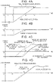
- FIGS. 3A through 3D are diagrams showing a control method of actuator systems, according to a reference example.
- FIG. 3A shows the change over time of the requested acceleration output as a kinematic plan from the ECU in which the ADAS application function is implemented.
- the requested acceleration of the vehicle turns positive at time t2, and reaches a final requested acceleration at time t3.
- FIG. 3B shows the change over time of the target braking force (negative driving force) for realizing the kinematic request shown in FIG. 3A .
- the target braking force linearly decreases from time t1 to time t2 in response to the increase in the requested acceleration, and the target braking force becomes zero after time t2.
- FIG. 3C shows the change over time of the target braking/driving force for realizing the kinematic request shown in FIG. 3A .
- a short-dashed line represents the target braking/driving force (FF term) calculated based on the requested acceleration
- a long-dashed line represents the target driving force (output value to the actuator system) that takes into consideration the FF term and the FB term.
- the target driving force is adjusted to be higher by the feedback control, following which the generated driving force of the powertrain actuator system suddenly increases.
- the target driving force is adjusted to be lower, and accordingly the generated driving force of the powertrain actuator system is reduced belatedly thereafter. Subsequently, the target driving force (long-dashed line) and the generated driving force (continuous line) repeat alternately increasing and decreasing in accordance with the feedback control.
- the actual acceleration of the vehicle increases and decreases as to the requested acceleration output as a kinematic request from the ADAS application, and time is needed for the actual acceleration to converge, which may lead to deterioration of riding comfort.
- the manager 10 can receive the first kinematic plan and the second kinematic plan following the first kinematic plan from the ECUs 1a to 1c, and accordingly the first kinematic plan and the second kinematic plan can be used to improve the response of the actuator system.
- the manager 10 determines whether the actuator systems include an actuator system of which the operating state needs to be switched, based on the first kinematic plan and the second kinematic plan that is the future kinematic plan following the first kinematic plan.
- the manager 10 resolves the response delay of the actuator system to be switched, by outputting, beforehand, a motion request for the actuator system of which the operating state needs to be switched. Control of the manager 10 according to the present embodiment will be described below with reference to FIGS. 4A through 4D .
- FIGS. 4A through 4D are diagrams showing a control method of actuator systems performed by the manager according to the embodiment.
- FIG. 4A shows the change over time of the requested acceleration received by the receiving unit 11 of the manager 10 as the first kinematic plan, and the final requested acceleration received as the second kinematic plan.
- the requested acceleration of the vehicle turns positive at time t2 in the same way as in the example in FIG. 3A , and reaches the final requested acceleration at time t3.
- the second kinematic plan it is sufficient for the second kinematic plan to be at a predetermined time following the first kinematic plan, and the time difference between the first kinematic plan and the second kinematic plan can be set as appropriate.
- the receiving unit 11 of the manager 10 can receive a requested acceleration (a) as the first kinematic plan at time t, and also receive a final requested acceleration (a') at time t3 as the second kinematic plan following an amount of time T from the first kinematic plan.
- FIG. 4B shows the change over time of the target braking force (negative driving force) for realizing the kinematic request shown in FIG. 4A .
- the target braking force linearly decreases from time t1 to time t2 in response to the increase in the requested acceleration, and the target braking force becomes zero after time t2.
- FIG. 4C shows the change over time of the target driving force for realizing the kinematic request shown in FIG. 4A .
- the thin continuous line represents the target driving force (FF term) calculated based on the requested acceleration.
- the target driving force (FF term, advance) represented by a short-dashed line is the target driving force (FF term) calculated based on the requested acceleration, which is output in advance a predetermined time before the target driving force (FF term).
- the target driving force (FF term, advance) of the short-dashed line corresponds to the target driving force (FF term) of the thin continuous line shifted in the negative direction on the horizontal axis by a predetermined amount of time.
- the long-dashed line represents the target driving force in which the FB term is added to the target driving force (FF term, advance).
- the calculation unit 13 of the manager 10 calculates the target driving force (FF term) based on the requested acceleration based on the first kinematic plan (thin continuous line in FIG. 4C ).
- the output unit 14 of the manager 10 outputs in advance the target driving force, calculated by the calculation unit 13, to the powertrain actuator system that has poor responsivity, by an amount of time equivalent to the response delay time DT of the actuator system (target driving force represented by the short-dashed line in FIG. 4C (FF term, advance)).
- the target driving force target driving force represented by the long-dashed line (FF term + FB term)
- the target driving force output to the powertrain actuator system is calculated based on the target driving force (FF term, advance) obtained by shifting the target driving force (FF term), calculated based on the requested driving force, earlier by a predetermined amount of time, with the response delay time DT of the powertrain actuator system taken into consideration beforehand.
- the shortage of the generated driving force (thick continuous line) with respect to the target driving force (FF term) calculated based on the requested acceleration can be reduced.
- the difference between the generated driving force of the powertrain actuator system and the target driving force is reduced, and thus increase or decrease in the generated driving force of the powertrain actuator system due to feedback control can be suppressed.
- the increase or decrease in the actual acceleration of the vehicle can be suppressed with respect to the requested acceleration output as the first kinematic request from the ADAS application, and the convergence of the actual acceleration can be improved, and accordingly the ride comfort can be improved.
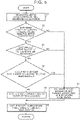
- FIG. 5 is a flowchart showing control processing performed by the manager according to the embodiment.
- the control processing in FIG. 5 is repeatedly executed during the execution of the ADAS application function.
- step S1 the receiving unit 11 receives the requested acceleration as the first kinematic plan, and the final requested acceleration as the second kinematic plan, from the ECUs 1a to 1c.
- the arbitration unit 12 performs arbitration processing, and the calculation unit 13 calculates the motion request for the actuator systems 2 and 3 based on the arbitration results. Thereafter, the processing proceeds to step S2.
- step S2 the calculation unit 13 determines whether there is a difference between the requested acceleration and the final requested acceleration.
- the output unit 14 may determine that there is a difference in step S2, when the difference between the requested acceleration and the final requested acceleration is not less than a predetermined threshold value.
- step S3 the processing proceeds to step S3, and otherwise, the processing proceeds to step S7 to calculate the target braking/driving force in accordance with the requested acceleration.
- step S3 the calculation unit 13 determines whether the operating state of the actuator system 2 or 3 needs to be switched. This determination can be made, for example, based on the difference between the requested acceleration and the final requested acceleration and the sameness of signs.
- step S3 the processing proceeds to step S4, and otherwise, the processing proceeds to step S7. Note that the processing of steps S4 and S6 may have already been executed before the determination in step S2. Accordingly, when NO is determined in step S2, the processing may proceed to step S7.
- step S4 the calculation unit 13 determines whether a first time point that is prior to a second time point has been reached.
- the second time point is a time point at which the requested acceleration is predicted to reach the final requested acceleration.
- the first time point is prior to the second time point by the response delay time (DT) of the actuator system. That is, the time difference between the first time point and the second time point is the response delay time (DT).
- DT response delay time
- step S5 the calculation unit 13 calculates the target braking/driving force (FF term, advance), in which the motion request (FF term of the target braking/driving force) calculated by the calculation unit 13 in step S1 is shifted to be earlier than the predicted switching time of the operation state that is identified based on the requested acceleration, by a predetermined amount of time.
- the response delay time DT of the actuator system described above may be used for the predetermined time.
- step S6 the calculation unit 13 calculates the target braking/driving force for output, taking the FB term into consideration in the target braking/driving force calculated in step S5 or step S7.
- the output unit 14 outputs the target braking/driving force calculated by the calculation unit to the actuator system of which the operating state needs to be switched, and the processing of this flowchart ends.
- the actuator systems include an actuator system of which the operating state needs to be switched, based on the requested acceleration and the final requested acceleration by performing the control processing shown in FIG. 5 , the target braking/driving force can be output beforehand, taking into consideration the operation delay of the actuator system. As a result, the capabilities of the actual acceleration to follow the requested acceleration can be improved, and deterioration of comfort of the ride can be suppressed.
- the manager 10 receives the first kinematic plan and the second kinematic plan following the first kinematic plan, from the ECUs 1a to 1c in each of which is implemented the ADAS application function.
- the manager 10 can comprehend the future kinematic plans, and can perform control that takes into consideration the response delay of the actuator system.
- the output unit 14 outputs, beforehand, a motion request for the actuator system of which the operating state needs to be switched. Accordingly, even when the responsivity of the actuator system of which the operating state needs to be switched is poor, delay in generating the braking/driving force by the actuator system can be suppressed.
- the output unit 14 outputs, beforehand, a motion request for the actuator system of which the operating state needs to be switched, based on the future requested acceleration (final requested acceleration) received as the second kinematic plan.
- output of motion requests that exceed the second kinematic plan that is the future kinematic plan can be suppressed.
- the output unit 14 controls the timing of advance output of the motion request to the actuator system of which the operating state needs to be switched, based on the responsivity information of the actuator system of which the operating state needs to be switched. Accordingly, the response delay can be appropriately suppressed in accordance with the operating characteristics of the actuator system.
- responsivity information is stored in the storage of the manager.
- a second receiving unit that receives the responsivity information from the actuator system may be provided.
- the responsivity information received from the actuator system by the second receiving unit may be stored in the storage.
- the responsivity information in the storage may be updated by Over the Air (OTA).
- OTA Over the Air
- the software that the ECU of the actuator system has is updated by OTA to improve functions.
- the responsivity information stored in the storage of the manager may be updated as well.
- the manager may download the update data by communicating with a server of a center, or an OTA master that controls the software updating of the entire vehicle may download the update data by communicating with the server, and transfer the update data to the manager.
- an example has been described in which the ECU in which the ADAS application function is implemented outputs the first kinematic plan and the second kinematic plan following the first kinematic plan to the manager.
- An output unit (second output unit) may be provided in the manager, to request the electronic control unit in which is implemented the ADAS application function for the second kinematic plan, when the ECU that implements the ADAS application function is not designed to spontaneously output the second kinematic plan that is the future kinematic plan.
- the functions of the manager exemplified in the above embodiment can also be realized as a vehicle control method executed by a computer including one or more processors (CPU), a memory, and a storage device, a vehicle control program executed by the computer, or a computer-readable non-transitory storage medium that stores the vehicle control program.
- a computer including one or more processors (CPU), a memory, and a storage device, a vehicle control program executed by the computer, or a computer-readable non-transitory storage medium that stores the vehicle control program.
- the present disclosure is applicable to a manager for controlling an actuator system and a vehicle provided therewith.
Applications Claiming Priority (1)
| Application Number | Priority Date | Filing Date | Title |
|---|---|---|---|
| JP2021044507A JP7453173B2 (ja) | 2021-03-18 | 2021-03-18 | マネージャ、車両制御方法及び車両制御プログラム、並びに、マネージャを備えた車両 |
Publications (1)
| Publication Number | Publication Date |
|---|---|
| EP4059798A1 true EP4059798A1 (en) | 2022-09-21 |
Family
ID=80684056
Family Applications (1)
| Application Number | Title | Priority Date | Filing Date |
|---|---|---|---|
| EP22160846.6A Pending EP4059798A1 (en) | 2021-03-18 | 2022-03-08 | Manager, vehicle control method, non-transitory storage medium, and vehicle |
Country Status (4)
| Country | Link |
|---|---|
| US (1) | US20220297702A1 (ja) |
| EP (1) | EP4059798A1 (ja) |
| JP (1) | JP7453173B2 (ja) |
| CN (1) | CN115158280A (ja) |
Citations (5)
| Publication number | Priority date | Publication date | Assignee | Title |
|---|---|---|---|---|
| WO2019033025A1 (en) * | 2017-08-10 | 2019-02-14 | Patroness, LLC | SYSTEMS AND METHODS FOR IMPROVED AUTONOMOUS OPERATIONS OF A MOTORIZED MOBILE SYSTEM |
| EP3617019A1 (en) * | 2018-08-30 | 2020-03-04 | Toyota Jidosha Kabushiki Kaisha | Control device |
| EP3617017A1 (en) * | 2018-08-30 | 2020-03-04 | Toyota Jidosha Kabushiki Kaisha | Information processing apparatus |
| US20200070873A1 (en) * | 2018-08-29 | 2020-03-05 | Toyota Jidosha Kabushiki Kaisha | Vehicle control system |
| JP2020032893A (ja) | 2018-08-30 | 2020-03-05 | トヨタ自動車株式会社 | 車両運動制御装置 |
Family Cites Families (11)
| Publication number | Priority date | Publication date | Assignee | Title |
|---|---|---|---|---|
| US20040034460A1 (en) * | 2002-08-13 | 2004-02-19 | Folkerts Charles Henry | Powertrain control system |
| JP4297107B2 (ja) * | 2005-10-26 | 2009-07-15 | トヨタ自動車株式会社 | 車両の制御装置 |
| JP4811199B2 (ja) | 2006-08-30 | 2011-11-09 | トヨタ自動車株式会社 | 車両の制駆動力制御装置 |
| JP5915499B2 (ja) | 2012-10-29 | 2016-05-11 | トヨタ自動車株式会社 | 車両走行制御装置 |
| JP6156403B2 (ja) * | 2015-02-13 | 2017-07-05 | トヨタ自動車株式会社 | 車両の駆動装置 |
| JP7212702B2 (ja) | 2019-01-21 | 2023-01-25 | 日立Astemo株式会社 | 車両制御装置、車両制御方法、及び車両制御システム |
| JP7221070B2 (ja) | 2019-02-07 | 2023-02-13 | 日立Astemo株式会社 | 電子制御装置、制御方法 |
| JP7192571B2 (ja) | 2019-02-28 | 2022-12-20 | トヨタ自動車株式会社 | 車両 |
| JP7368206B2 (ja) * | 2019-12-09 | 2023-10-24 | トヨタ自動車株式会社 | 制御装置 |
| JP7318550B2 (ja) * | 2020-02-04 | 2023-08-01 | トヨタ自動車株式会社 | 制御装置、方法、プログラム、及び車両 |
| JP7327230B2 (ja) * | 2020-03-18 | 2023-08-16 | トヨタ自動車株式会社 | 制御装置を備える車両、方法、プログラム |
-
2021
- 2021-03-18 JP JP2021044507A patent/JP7453173B2/ja active Active
-
2022
- 2022-03-02 CN CN202210202982.7A patent/CN115158280A/zh active Pending
- 2022-03-08 EP EP22160846.6A patent/EP4059798A1/en active Pending
- 2022-03-16 US US17/696,018 patent/US20220297702A1/en active Pending
Patent Citations (5)
| Publication number | Priority date | Publication date | Assignee | Title |
|---|---|---|---|---|
| WO2019033025A1 (en) * | 2017-08-10 | 2019-02-14 | Patroness, LLC | SYSTEMS AND METHODS FOR IMPROVED AUTONOMOUS OPERATIONS OF A MOTORIZED MOBILE SYSTEM |
| US20200070873A1 (en) * | 2018-08-29 | 2020-03-05 | Toyota Jidosha Kabushiki Kaisha | Vehicle control system |
| EP3617019A1 (en) * | 2018-08-30 | 2020-03-04 | Toyota Jidosha Kabushiki Kaisha | Control device |
| EP3617017A1 (en) * | 2018-08-30 | 2020-03-04 | Toyota Jidosha Kabushiki Kaisha | Information processing apparatus |
| JP2020032893A (ja) | 2018-08-30 | 2020-03-05 | トヨタ自動車株式会社 | 車両運動制御装置 |
Also Published As
| Publication number | Publication date |
|---|---|
| CN115158280A (zh) | 2022-10-11 |
| US20220297702A1 (en) | 2022-09-22 |
| JP7453173B2 (ja) | 2024-03-19 |
| JP2022143795A (ja) | 2022-10-03 |
Similar Documents
| Publication | Publication Date | Title |
|---|---|---|
| US20230227048A1 (en) | Vehicle control system | |
| US11738762B2 (en) | Control device, manager, method, non-transitory storage medium, actuator system, and vehicle | |
| US11834037B2 (en) | Control device, method, non-transitory storage medium, and vehicle | |
| US11110794B2 (en) | Vehicle control apparatus | |
| US11952002B2 (en) | Control device, control method and non-transitory storage medium | |
| US11780500B2 (en) | Control device, manager, method, non-transitory storage medium, and vehicle | |
| EP4059798A1 (en) | Manager, vehicle control method, non-transitory storage medium, and vehicle | |
| JP2022186829A (ja) | 制御装置、方法、およびプログラム | |
| US11897477B2 (en) | Control device for vehicle, control method, non-transitory computer-readable storage medium, manager, and vehicle | |
| JP7444806B2 (ja) | 車両の制御装置、制御方法、制御プログラム、マネージャ、及び車両 | |
| US20220315018A1 (en) | Control apparatus, manager, electronic control unit, system, control method, non-transitory computer-readable storage medium storing program, and vehicle | |
| JP2022139254A (ja) | マネージャ、電子制御ユニット、システム、制御方法、制御プログラム、及び車両 | |
| JP2022187753A (ja) | マネージャ、制御方法、制御プログラム、及び車両 |
Legal Events
| Date | Code | Title | Description |
|---|---|---|---|
| PUAI | Public reference made under article 153(3) epc to a published international application that has entered the european phase |
Free format text: ORIGINAL CODE: 0009012 |
|
| STAA | Information on the status of an ep patent application or granted ep patent |
Free format text: STATUS: REQUEST FOR EXAMINATION WAS MADE |
|
| 17P | Request for examination filed |
Effective date: 20220308 |
|
| AK | Designated contracting states |
Kind code of ref document: A1 Designated state(s): AL AT BE BG CH CY CZ DE DK EE ES FI FR GB GR HR HU IE IS IT LI LT LU LV MC MK MT NL NO PL PT RO RS SE SI SK SM TR |
|
| GRAP | Despatch of communication of intention to grant a patent |
Free format text: ORIGINAL CODE: EPIDOSNIGR1 |
|
| STAA | Information on the status of an ep patent application or granted ep patent |
Free format text: STATUS: GRANT OF PATENT IS INTENDED |
|
| INTG | Intention to grant announced |
Effective date: 20240228 |
|
| RIN1 | Information on inventor provided before grant (corrected) |
Inventor name: FUKUKAWA, SHOGI Inventor name: ARAKAWA, SHUNSUKE Inventor name: ITOH, NOBUYUKI |