EP4059529B1 - Nasenschleimabsaugvorrichtung und kanalbildungsverfahren dafür - Google Patents
Nasenschleimabsaugvorrichtung und kanalbildungsverfahren dafür Download PDFInfo
- Publication number
- EP4059529B1 EP4059529B1 EP22162074.3A EP22162074A EP4059529B1 EP 4059529 B1 EP4059529 B1 EP 4059529B1 EP 22162074 A EP22162074 A EP 22162074A EP 4059529 B1 EP4059529 B1 EP 4059529B1
- Authority
- EP
- European Patent Office
- Prior art keywords
- channel
- mucus
- channel section
- nasal mucus
- communication
- Prior art date
- Legal status (The legal status is an assumption and is not a legal conclusion. Google has not performed a legal analysis and makes no representation as to the accuracy of the status listed.)
- Active
Links
Images



Classifications
-
- A—HUMAN NECESSITIES
- A61—MEDICAL OR VETERINARY SCIENCE; HYGIENE
- A61M—DEVICES FOR INTRODUCING MEDIA INTO, OR ONTO, THE BODY; DEVICES FOR TRANSDUCING BODY MEDIA OR FOR TAKING MEDIA FROM THE BODY; DEVICES FOR PRODUCING OR ENDING SLEEP OR STUPOR
- A61M1/00—Suction or pumping devices for medical purposes; Devices for carrying-off, for treatment of, or for carrying-over, body-liquids; Drainage systems
- A61M1/71—Suction drainage systems
- A61M1/78—Means for preventing overflow or contamination of the pumping systems
-
- A—HUMAN NECESSITIES
- A61—MEDICAL OR VETERINARY SCIENCE; HYGIENE
- A61M—DEVICES FOR INTRODUCING MEDIA INTO, OR ONTO, THE BODY; DEVICES FOR TRANSDUCING BODY MEDIA OR FOR TAKING MEDIA FROM THE BODY; DEVICES FOR PRODUCING OR ENDING SLEEP OR STUPOR
- A61M1/00—Suction or pumping devices for medical purposes; Devices for carrying-off, for treatment of, or for carrying-over, body-liquids; Drainage systems
- A61M1/64—Containers with integrated suction means
-
- A—HUMAN NECESSITIES
- A61—MEDICAL OR VETERINARY SCIENCE; HYGIENE
- A61M—DEVICES FOR INTRODUCING MEDIA INTO, OR ONTO, THE BODY; DEVICES FOR TRANSDUCING BODY MEDIA OR FOR TAKING MEDIA FROM THE BODY; DEVICES FOR PRODUCING OR ENDING SLEEP OR STUPOR
- A61M1/00—Suction or pumping devices for medical purposes; Devices for carrying-off, for treatment of, or for carrying-over, body-liquids; Drainage systems
- A61M1/64—Containers with integrated suction means
- A61M1/65—Containers with integrated suction means the suction means being electrically actuated
-
- A—HUMAN NECESSITIES
- A61—MEDICAL OR VETERINARY SCIENCE; HYGIENE
- A61M—DEVICES FOR INTRODUCING MEDIA INTO, OR ONTO, THE BODY; DEVICES FOR TRANSDUCING BODY MEDIA OR FOR TAKING MEDIA FROM THE BODY; DEVICES FOR PRODUCING OR ENDING SLEEP OR STUPOR
- A61M1/00—Suction or pumping devices for medical purposes; Devices for carrying-off, for treatment of, or for carrying-over, body-liquids; Drainage systems
- A61M1/84—Drainage tubes; Aspiration tips
- A61M1/87—Details of the aspiration tip, not otherwise provided for
-
- A—HUMAN NECESSITIES
- A61—MEDICAL OR VETERINARY SCIENCE; HYGIENE
- A61M—DEVICES FOR INTRODUCING MEDIA INTO, OR ONTO, THE BODY; DEVICES FOR TRANSDUCING BODY MEDIA OR FOR TAKING MEDIA FROM THE BODY; DEVICES FOR PRODUCING OR ENDING SLEEP OR STUPOR
- A61M2202/00—Special media to be introduced, removed or treated
- A61M2202/04—Liquids
-
- A—HUMAN NECESSITIES
- A61—MEDICAL OR VETERINARY SCIENCE; HYGIENE
- A61M—DEVICES FOR INTRODUCING MEDIA INTO, OR ONTO, THE BODY; DEVICES FOR TRANSDUCING BODY MEDIA OR FOR TAKING MEDIA FROM THE BODY; DEVICES FOR PRODUCING OR ENDING SLEEP OR STUPOR
- A61M2205/00—General characteristics of the apparatus
- A61M2205/07—General characteristics of the apparatus having air pumping means
-
- A—HUMAN NECESSITIES
- A61—MEDICAL OR VETERINARY SCIENCE; HYGIENE
- A61M—DEVICES FOR INTRODUCING MEDIA INTO, OR ONTO, THE BODY; DEVICES FOR TRANSDUCING BODY MEDIA OR FOR TAKING MEDIA FROM THE BODY; DEVICES FOR PRODUCING OR ENDING SLEEP OR STUPOR
- A61M2205/00—General characteristics of the apparatus
- A61M2205/42—Reducing noise
-
- A—HUMAN NECESSITIES
- A61—MEDICAL OR VETERINARY SCIENCE; HYGIENE
- A61M—DEVICES FOR INTRODUCING MEDIA INTO, OR ONTO, THE BODY; DEVICES FOR TRANSDUCING BODY MEDIA OR FOR TAKING MEDIA FROM THE BODY; DEVICES FOR PRODUCING OR ENDING SLEEP OR STUPOR
- A61M2207/00—Methods of manufacture, assembly or production
-
- A—HUMAN NECESSITIES
- A61—MEDICAL OR VETERINARY SCIENCE; HYGIENE
- A61M—DEVICES FOR INTRODUCING MEDIA INTO, OR ONTO, THE BODY; DEVICES FOR TRANSDUCING BODY MEDIA OR FOR TAKING MEDIA FROM THE BODY; DEVICES FOR PRODUCING OR ENDING SLEEP OR STUPOR
- A61M2210/00—Anatomical parts of the body
- A61M2210/06—Head
- A61M2210/0618—Nose
Definitions
- the present invention relates to a nasal mucus suction device. More particularly, the present invention relates to a nasal mucus suction device capable of preventing backflow of nasal mucus and reducing noise, and a channel forming method thereof.
- Nasal cleaning and medical care are very important clinically, so products with nasal mucus suction functions are developed for cleaning or medical use. Especially in home care, it is necessary to provide simple and quick nasal care including a function of sucking of patient's nasal mucus or phlegm.
- the nasal mucus suction device uses an air pump as a power source to generate suction, but unnecessary noise is often caused by the air pump during the operation of the nasal mucus suction device.
- the conventional nasal mucus suction device in order to prevent the stored nasal mucus from overflowing, the conventional nasal mucus suction device must have a limitation in a holding angle; however, when the user operates the conventional nasal mucus suction device and rotates the holding angle of the conventional nasal mucus suction device, nasal mucus easily overflows an outer shell of the conventional nasal mucus suction device.
- the present invention provides a nasal mucus suction device having a channel for preventing backflow of nasal mucus and reducing noise, and a channel forming method thereof, so as to improve practicability in the industry.
- Chinese Patent CN109152869A discloses an accessory for a nasal aspirator, the accessory comprising an accessory body suitable to be gripped and a terminal nozzle placed at a distal end of said accessory body and suitable to be at least partially inserted into a nostril of a user.
- the accessory fails to disclose a noise reduction space, and the channel in the nasal aspirator is not long enough to prevent backflow.
- An objective of the present invention is to disclose a nasal mucus suction device and a channel forming method, and provide a structure formed in a nasal mucus suction channel to prevent backflow and overflow of nasal mucus.
- Another objective of the present invention is to disclose a nasal mucus suction device and a channel forming method thereof, to provide a noise reduction structure formed in an outlet channel to reduce noise caused by operation of an air pump.
- the present invention provides a nasal mucus suction device including an air pump and a head structure.
- the air pump includes an intake tube and an outlet tube.
- the head structure is coupled to the intake tube and the outlet tube of the air pump, wherein the head structure defines a channel between a nasal mucus suction inlet and a gas outlet, the channel includes a first channel section in communication with the nasal mucus suction inlet, and a second channel section in communication with the gas outlet, the first channel section includes at least one mucus storage cavity, and the second channel section in communication with the intake tube and the outlet tube of the air pump.
- the first channel section includes an air channel and a nasal mucus channel, the second section is extended from the air channel to the gas outlet.
- the nasal mucus suction device is characterized in that: the outer cup comprises a lower ring wall extended from a bottom of an inner side thereof, and the inner cup comprises an upper ring wall extended from a bottom of an outer side thereof and surrounding a lower ring wall of the outer cup, wherein the upper ring wall and the lower ring wall form a plurality of curved paths of the first channel section inside the second mucus storage cavity; the noise reduction space and the gas outlet are spaced by two partition plates, each of which forms a small groove thereon, so that noise goes into the noise reduction space with air through the small grooves and is circulated therein.
- the first channel section of the head structure includes a front cover, an inner cup and an outer cup.
- the front cover includes the nasal mucus suction inlet.
- the inner cup includes the first mucus storage cavity in communication with the nasal mucus suction inlet.
- the outer cup includes the second mucus storage cavity in communication with the intake tube of the air pump, wherein the second mucus storage cavity accommodates at least one part of the inner cup, so that nasal mucus overflowing from the first mucus storage cavity is accommodated in the second mucus storage cavity.
- the first channel section further includes a cup cover having a flow guidance tube, the cup cover is coupled to between the front cover and the cup lid, so that the guidance tube passes through the opening of the cup lid, the flow guidance tube guides nasal mucus from the nasal mucus suction inlet to flow into the first mucus storage cavity.
- the outer cup includes a middle tube formed on a bottom thereof, the middle tube is in communication with the intake tube of the air pump and the second mucus storage cavity, and an inner channel length of the middle tube is greater than a bottom thickness of the outer cup.
- the lower ring wall surrounds the middle tube.
- the second channel section of the head structure includes a connection block
- the connection block includes an intake channel and an outlet channel
- the intake channel is in communication with the second mucus storage cavity of the outer cup and the intake tube of the air pump
- the outlet channel is in communication with the outlet tube and the gas outlet of the air pump.
- the first channel section includes a cup lid having an opening, and the cup lid covers a cup edge of the inner cup.
- the present invention provides a channel forming method for a nasal mucus suction device
- the nasal mucus suction device includes an air pump and a head structure
- the air pump includes an intake tube and an outlet tube
- the head structure defines a channel between a nasal mucus suction inlet and a gas outlet
- the channel comprises a first channel section in communication with the nasal mucus suction inlet, and a second channel section in communication with the gas outlet
- the channel forming method includes steps of: forming a plurality of curved paths in the first channel section; disposing at least one mucus storage cavity in the first channel section; disposing a noise reduction space in the second channel section and in communication with the outlet tube of the air pump, wherein the noise reduction space (162) has two small grooves formed on walls thereof, so that noise goes into the noise reduction space (162) with air through the small grooves and is circulated therein.
- the channel forming method of the present invention further includes steps of: disposing a front cover in the first channel section, wherein the front cover includes a nasal mucus suction inlet; disposing an inner cup in the first channel section, wherein the inner cup includes a first mucus storage cavity in communication with the nasal mucus suction inlet; disposing an outer cup in the first channel section, wherein the outer cup includes a second mucus storage cavity in communication with the intake tube of the air pump and configured to accommodate at least one part of the inner cup, so that the nasal mucus overflowing from the first mucus storage cavity is accommodated in the second mucus storage cavity.
- the channel forming method further includes a step of forming the plurality of curved paths of the first channel section in the second mucus storage cavity between an outer side bottom of the inner cup and an inner side bottom of the outer cup.
- the channel forming method further includes steps of: disposing a base in the second channel section to define the noise reduction space in communication with the gas outlet; disposing a connection block in the second channel section, wherein the connection block includes an intake channel and an outlet channel, and the intake channel is in communication with the first channel section and the intake tube of the air pump, and the outlet channel is in communication with the outlet tube and the gas outlet of the air pump.
- the nasal mucus suction device and the channel forming method of the present invention can prevent nasal mucus from easily overflowing when a user holds the nasal mucus suction device and rotate a holding angle, and the noise reduction structure in the channel can effectively reduce the noise caused by the air pump when the device of the present invention is in operation.
- a nasal mucus suction device includes a head structure 10 and an air pump 20, and the air pump 20 includes an intake tube 22 and an outlet tube 21.
- the head structure 10 is coupled to the intake tube 22 and the outlet tube 21 of the air pump 20.
- the head structure 10 is formed by a front cover 11, a cup cover 12, a cup lid 13, an inner cup 14, an outer cup 15, a base 16 and a connection block 17;
- the inner cup 14 includes a first mucus storage cavity 142, and the outer cup 15 includes a second mucus storage cavity 153.
- Fig. 1 shows an exploded view of a nasal mucus suction device of the present invention.
- a nasal mucus suction device includes a head structure 10 and an air pump 20, and the air pump 20 includes an intake tube 22 and an outlet tube 21.
- the head structure 10 is coupled to the intake tube 22 and the outlet tube 21 of the air pump 20.
- the head structure 10 is formed by a front cover 11, a cup cover 12, a cup lid 13, an inner cup 14,
- an O-shaped ring 1 is disposed between an outer side of the inner cup 14 and an inner side of the outer cup 15, to restrict the flowing path for the nasal mucus overflowing the first mucus storage cavity 142; that is, the O-shaped ring 1 disposed between the outer side of the outer cup 15 and the inner side of the cup cover 12 prevents the nasal mucus overflowing the first mucus storage cavity 142 from flowing outside the cup cover 12.
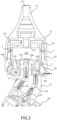
- Fig. 2 shows a sectional view of a head structure of a coupled to the air pump 20, according to a nasal mucus suction device of the present invention, and Fig. 2 is taken along a section line BB of Fig. 5 .
- the front cover 11 includes a nasal mucus suction inlet 111
- the base 16 includes a gas outlet 161.
- the head structure 10 defines a channel between a nasal mucus suction inlet 111 and a gas outlet 161.
- the channel includes a first channel section in communication with the nasal mucus suction inlet 111, and a second channel section in communication with the gas outlet 161;
- the first channel section serves as a common channel for an air channel and the nasal mucus channel and include paths A, B, C, D and E, as shown in Fig. 3 ;
- the second channel section is extended from the air channel of the first channel section to the gas outlet 161, and includes paths F, G, H, I and J, as shown in Fig. 2 .
- Fig. 3 shows a sectional view of a head structure of a nasal mucus suction device of the present invention
- Fig. 3 is taken along section line AA of Fig. 5 .
- the front cover 11 includes a hollow channel in a trumpet shape, and is coupled to the cup cover 12.
- the nasal mucus suction inlet 111 is in communication with the hollow channel of the front cover 11.
- the cup cover 12 includes a flow guidance tube 121. As shown in Fig.
- the cup lid 13 includes an opening 131, an internal diameter of the opening 131 is slightly greater than an outer diameter of the flow guidance tube 121, so that the nasal mucus stored in the first mucus storage cavity 142 can overflow to a space between the inner cup 14 and the cup cover 12 through an edge of the opening 131 (such as the path B).
- the cup lid 13 has a protruding edge structure formed on a lower surface thereof and near a periphery thereof, and the protruding edge structure is used to make the cup lid 13 tightly cover the cup edge of the inner cup 14.
- the flow guidance tube 121 of the cup cover 12 is inserted into the first mucus storage cavity 142 of the inner cup 14 through the opening 131 of the cup lid 13, so that the nasal mucus from the nasal mucus suction inlet 111 is stored in the first mucus storage cavity 142 of the inner cup 14 through the flow guidance tube 121.
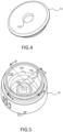
- FIG. 5 shows a perspective view of the outer cup 15 of the nasal mucus suction device of the present invention.
- the outer cup 15 includes a second mucus storage cavity 153, the second mucus storage cavity 153 has a protruding edge 155 formed on an inner sidewall thereof, the protruding edge 155 is configured to support a bottom periphery of the inner cup 14.
- the second mucus storage cavity 153 has a middle tube 154 formed on a central part of a bottom (the space below the protruding edge 155) thereof, and an inner channel length of the middle tube 154 is greater than a bottom thickness of the outer cup 15.
- a lower ring wall 151 is extended from the bottom of the second mucus storage cavity 153 to surround the middle tube 154, and a height of the lower ring wall 151 is lower than a height of the middle tube 154.
- the inner cup 14 includes an upper ring wall 141 extended from a bottom of an outer side thereof.
- the upper ring wall 141 surrounds the lower ring wall 151 of the outer cup 15, and the upper ring wall 141 and the lower ring wall 151 form a plurality of curved paths E of the first channel section inside the second mucus storage cavity 153 (as shown in Fig.
- the inner side of the cup cover 12 is downwardly extended to cover a part of the outer side of the outer cup 15, and the O-shaped ring 1 disposed between the outer side of the outer cup 15 and the inner side of the cup cover 12 prevents the nasal mucus overflowing the first mucus storage cavity 142 from flowing to outside the cup cover 12.
- Fig. 6 shows a perspective view of a base 16 of a nasal mucus suction device of the present invention.
- the base 16 includes an annular inner wall 164; the annular inner wall 164 defines a channel in a central part of the base 16, and the channel is configured to link the intake channel 171 of the connection block 17.
- the base 16 is coupled to the bottom of the outer cup 15, the bottom surface of the outer cup 15 is supported by the annular inner wall 164, and the middle tube 154 on the bottom of the outer cup 15 is inserted into the intake channel 171 of the connection block 17.
- the annular inner wall 164 defines an annular noise reduction space 162 inside the base 16, and an outlet chamber having a gas outlet 161.
- the outlet chamber includes a hole 163 in communication with the outlet channel 172 of the connection block 17.
- the noise reduction space 162 and the outlet chamber are spaced by two partition plates, the two partition plates form a small groove, so that the noise entering the outlet chamber through the hole 163 is circulated to the noise reduction space 162 with air through the small groove, thereby achieving the effect of reducing noise.
- the O-shaped ring 1 disposed between the outer edge of the base 16 and the outer cup 15 can be made by rubber, so as to effectively isolate the noise of the air pump 20 inside the noise reduction space 162, thereby optimizing the noise reduction effect of the nasal mucus suction device of the present invention.
- connection block 17 is coupled between the bottom of the base 16 and the air pump 20, and the connection block 17 forms an intake channel 171 and an outlet channel 172 independent from each other.
- the intake channel 171 is in communication with the middle tube 154 of the outer cup 15 and the intake tube 22 of the air pump 20, and the outlet channel 172 is in communication with the hole 163 of the base 16 and the outlet tube 21 of the air pump 20.
- the connection block 17 is used to make the intake tube 22 of the air pump 20 in communication with the second mucus storage cavity 153 of the outer cup 15, and make the outlet tube 21 of the air pump 20 in communication with the noise reduction space 162 of the base 16.
- the first channel section of the head structure 10 includes the paths A, B, C, D and E, and includes the first mucus storage cavity 142 passing through the inner cup 14 and the second mucus storage cavity 153 passing through the outer cup 15.
- the channel between the nasal mucus suction inlet 111 and the gas outlet 161 provide a common channel for the air channel and the nasal mucus channel.
- the middle tube 154 of the outer cup 15 is in communication with the intake tube 22 of the air pump 20, and when a suction force is generated in the path F, the nasal mucus from the nasal mucus suction inlet 111 can stay in the first mucus storage cavity 142 and the second mucus storage cavity 153 along the paths A, B, C, D and E.
- a groove 152 is formed on an inner sidewall of the outer cup 15, and the section line AA passes through the groove 152.
- the groove 152 provides an overflowing path C for nasal mucus not restricted by the O-shaped ring 1 between the outer sidewall of the inner cup 14 and the inner sidewall of the outer cup 15.
- the nasal mucus overflowing through the path B from the first mucus storage cavity 142 only can flow into between the outer sidewall of the inner cup 14 and the inner sidewall of the outer cup 15 through the path C of the groove 152.
- the inner cup 14 has a groove formed on the bottom thereof to provide a path D, so that the nasal mucus between the outer sidewall of the inner cup 14 and the inner sidewall of the outer cup 15 flows into the second mucus storage cavity 153 under the inner cup 14 through the path D. More particularly, the groove of the path D is disposed opposite to the groove 152 of the outer cup 15, so that the path length of the first channel section can be maximized.
- the plurality of curved paths E formed by the upper ring wall 141 of the inner cup 14 and the lower ring wall 151 of the outer cup 15 in the second mucus storage cavity 153 can maximize the path length of the first channel section for flowing nasal mucus. Maximizing the path length of the first channel section can prevent the nasal mucus stored in the second mucus storage cavity 153 from backflowing to the nasal mucus suction inlet 111 when the air pump 20 of the nasal mucus suction device of the present invention is not in operation.
- the height of the lower ring wall 151 is lower than the height of the middle tube 154, so that the nasal mucus stored in the second mucus storage cavity 153 is prevented from flowing into the second channel section; furthermore, the middle tube 154 disposed on the central part can deflect the angle of holding the nasal mucus suction device, to prevent the nasal mucus stored in the second mucus storage cavity 153 from flowing to the second channel section easily.
- Fig. 2 is a sectional view taken along a section line BB of Fig. 5 .
- the section line BB is perpendicular to the section line AA
- Figs. 2 and 3 show different sectional views of the head structure 10.
- the second channel section of the head structure 10 includes the paths F, G, H, I and J, and the noise reduction space 162 of the base 16.
- the second channel section is extended from the air channel of the first channel section to the gas outlet 161.
- the intake tube 22 and the outlet tube 21 of the air pump 20 pass through the intake channel 171 and the outlet channel 172 of the connection block 17 to be in communication with the middle tube 154 of the outer cup 15 and the hole 163 of the base 16, respectively.
- the intake tube 22 of the air pump 20 When the air pump 20 is in operation, the intake tube 22 of the air pump 20 generates a suction force in the paths F and G, and exhaust through the outlet tube 21 to the noise reduction space 162 and the gas outlet 161. Therefore, the noise generated by operation of the air pump 20 stays in the noise reduction space 162 through the paths H and I.
Landscapes
- Health & Medical Sciences (AREA)
- Heart & Thoracic Surgery (AREA)
- Biomedical Technology (AREA)
- Vascular Medicine (AREA)
- Engineering & Computer Science (AREA)
- Anesthesiology (AREA)
- Hematology (AREA)
- Life Sciences & Earth Sciences (AREA)
- Animal Behavior & Ethology (AREA)
- General Health & Medical Sciences (AREA)
- Public Health (AREA)
- Veterinary Medicine (AREA)
- Surgery (AREA)
- External Artificial Organs (AREA)
Claims (14)
- Nasenschleim-Absauggerät, das eine Luftpumpe (20) und eine Kopfstruktur (10) umfasst, wobei die Luftpumpe (20) ein Ansaugrohr (22) und ein Auslassrohr (21) umfasst, wobei die Kopfstruktur (10) mit dem Ansaugrohr (22) und dem Auslassrohr (21) der Luftpumpe (20) gekoppelt ist, wobei die Kopfstruktur (10) einen Nasenschleim-Saugeinlass (111), einen Gasauslass (161) und einen zwischen dem Nasenschleim-Saugeinlass (111) und dem Gasauslass (161) definierten Kanal aufweist, wobei der Kanal einen ersten Kanalabschnitt, der mit dem Nasenschleim-Saugeinlass (111) in Verbindung steht, und einen zweiten Kanalabschnitt, der mit dem Gasauslass (161) in Verbindung steht, umfasst, wobei der erste Kanalabschnitt mindestens einen Schleimspeicherhohlraum aufweist und der zweite Kanalabschnitt mit dem Ansaugrohr (22) und dem Auslassrohr (21) der Luftpumpe (20) in Verbindung steht, wobei der erste Kanalabschnitt einen Luftkanal und einen Nasenschleimkanal aufweist, wobei sich der zweite Abschnitt vom Luftkanal zum Gasauslass (161) erstreckt, wobei der zweite Kanalabschnitt einen Geräuschminderungsraum (162) aufweist, der mit dem Auslassrohr (21) der Luftpumpe (20) in Verbindung steht, wobei das Nasenschleim-Absauggerät dadurch gekennzeichnet ist,dass der Außendeckel (15) eine untere Ringwand (151) umfasst, die sich von einem Boden einer Innenseite davon erstreckt, und der Innendeckel (14) eine obere Ringwand (141) umfasst, die sich von einem Boden einer Außenseite davon erstreckt und eine untere Ringwand (151) des Außendeckels (15) umgibt, wobei die obere Ringwand (141) und die untere Ringwand (151) eine Vielzahl gekrümmter Pfade des ersten Kanalabschnitts innerhalb des zweiten Schleimspeicherhohlraums (153) bilden; unddass der Geräuschminderungsraum (162) und der Gasauslass (161) durch zwei Trennplatten voneinander getrennt sind, von denen jede eine kleine Rille darauf bildet, so dass Lärm mit Luft durch die kleinen Rillen in den Geräuschminderungsraum (162) gelangt und darin zirkuliert wird.
- Nasenschleim-Absauggerät nach Anspruch 1,
dadurch gekennzeichnet,
dass der erste Kanalabschnitt der Kopfstruktur (10) umfasst:- eine vordere Abdeckung (11), die den Nasenschleim-Saugeinlass (111) aufweist,- einen Innendeckel (14), der den ersten Schleimspeicherhohlraum (142) aufweist, der mit dem Nasenschleim-Saugeinlass (111) in Verbindung steht, und- einen Außendeckel (15), der den zweiten Schleimspeicherhohlraum (153) aufweist, der mit dem Ansaugrohr (22) der Luftpumpe (20) in Verbindung steht, wobei der zweite Schleimspeicherhohlraum (153) mindestens einen Teil des Innendeckels (14) aufnimmt, so dass aus dem ersten Schleimspeicherhohlraum (142) überlaufender Nasenschleim in dem zweiten Schleimspeicherhohlraum (153) aufgenommen wird. - Nasenschleim-Absauggerät nach Anspruch 2,
dadurch gekennzeichnet,
dass der Außenbecher (15) ein Mittelrohr (154) umfasst, das an einem Boden des Außenbechers (15) ausgebildet ist und mit dem Ansaugrohr (22) der Luftpumpe (20) und dem zweiten Schleimspeicherhohlraum (153) in Verbindung steht, wobei eine innere Kanallänge des Mittelrohrs (154) größer ist als eine Bodendicke des Außenbechers (15). - Nasenschleim-Absauggerät nach Anspruch 3,
dadurch gekennzeichnet,
dass die untere Ringwand (151) das Mittelrohr (154) umgibt. - Nasenschleim-Absauggerät nach Anspruch 1,
dadurch gekennzeichnet,
dass ein Verbindungsblock (17) im zweite Kanalabschnitt der Kopfstruktur (10) vorgesehen ist, wobei der Verbindungsblock (17) einen Einlasskanal (171), der mit dem zweiten Schleimspeicherhhohlraum (153) des Außenbechers (15) und dem Einlassrohr (22) der Luftpumpe (20) in Verbindung steht, und einen Auslasskanal (172), der mit dem Auslassrohr (21) und dem Gasauslass (161) der Luftpumpe (20) in Verbindung steht, umfasst. - Nasenschleim-Absauggerät nach Anspruch 2,
dadurch gekennzeichnet,
dass der erste Kanalabschnitt einen Becherdeckel (13) umfasst, der eine Öffnung (131) aufweist und einen Becherrand des Innenbechers (14) bedeckt. - Nasenschleim-Absauggerät nach Anspruch 6,
dadurch gekennzeichnet,
dass der erste Kanalabschnitt ferner eine Becherabdeckung (12) mit einem Strömungsführungsrohr (121) umfasst, wobei die Becherabdeckung (12) zwischen der vorderen Abdeckung (11) und dem Becherdeckel (13) angebracht und mit diesen beiden gekoppelt ist, so dass das Strömungsführungsrohr (121) durch die Öffnung (131) des Becherdeckels (13) verläuft und das Strömungsführungsrohr (121) Nasenschleim vom Nasenschleim-Saugeinlass (111) in den ersten Schleimspeicherhohlraum (142) leitet. - Nasenschleim-Absauggerät nach Anspruch 1,
dadurch gekennzeichnet,
dass die Kopfstruktur (10) ferner eine Basis (16) umfasst, die im zweiten Kanalabschnitt angeordnet ist, wobei die Basis (16) einen Geräuschminderungsraum (162) definiert, der mit dem Gasauslass (161) in Verbindung steht. - Nasenschleim-Absauggerät nach Anspruch 8,
dadurch gekennzeichnet,
dass die Kopfstruktur (10) ferner einen Verbindungsblock (17) umfasst, der im zweiten Kanalabschnitt angeordnet ist, wobei der Verbindungsblock (17) einen Einlasskanal (171), der mit dem ersten Kanalabschnitt und dem Einlassrohr (22) der Luftpumpe (20) in Verbindung steht, und einen Auslasskanal (172), der mit dem Auslassrohr (21) und dem Gasauslass (161) der Luftpumpe (20) in Verbindung steht, umfasst. - Verfahren zur Bildung eines Kanals für ein Nasenschleim-Absauggerät, welches Nasenschleim-Absauggerät eine Luftpumpe (20) und eine Kopfstruktur (10) umfasst, wobei die Luftpumpe (20) ein Ansaugrohr (22) und ein Auslassrohr (21) umfasst, wobei die Kopfstruktur (10) einen zwischen einem Nasenschleim-Saugeinlass (111) und einem Gasauslass (161) definierten Kanal aufweist, wobei der Kanal einen ersten Kanalabschnitt, der mit dem Nasenschleim-Saugeinlass (111) in Verbindung steht, und einen zweiten Kanalabschnitt, der mit dem Gasauslass (161) in Verbindung steht, umfasst, wobei das Verfahren zur Bildung eines Kanals folgende Schritte umfasst:- Bilden einer Vielzahl gekrümmter Pfade im ersten Kanalabschnitt,- Anordnen mindestens eines Schleimspeicherhohlraums im ersten Kanalabschnitt, und- Anordnen eines Geräuschminderungsraums (162) im zweiten Kanalabschnitt derart, dass der Geräuschminderungsraum (162) mit dem Auslassrohr (21) der Luftpumpe (20) in Verbindung steht, wobei der Geräuschminderungsraum (162) zwei kleine Rillen aufweist, die an seinen Wänden ausgebildet sind, so dass Geräusche mit Luft durch die kleinen Rillen in den Geräuschminderungsraum (162) gelangen und darin zirkuliert werden.
- Verfahren zur Bildung eines Kanals nach Anspruch 10,
dadurch gekennzeichnet,
dass das Verfahren weiter folgende Schritte umfasst:- Anordnen einer vorderen Abdeckung (11) im ersten Kanalabschnitt, wobei die vordere Abdeckung (11) einen Nasenschleim-Saugeinlass (111) umfasst,- Anordnen eines Innenbechers (14) im ersten Kanalabschnitt, wobei der Innenbecher (14) einen ersten Schleimspeicherhohlraum (142) umfasst, der mit dem Nasenschleim-Saugeinlass (111) in Verbindung steht, und- Anordnen eines Außenbechers (15) im ersten Kanalabschnitt, wobei der Außenbecher (15) einen zweiten Schleimspeicherhohlraum (153) umfasst, der mit dem Ansaugrohr (22) der Luftpumpe (20) in Verbindung steht und so konfiguriert ist, dass sie mindestens einen Teil des Innenbechers (14) aufnehmen kann, so dass der aus dem ersten Schleimspeicherhohlraum (142) überlaufende Nasenschleim im zweiten Schleimspeicherhohlraum (153) aufgenommen wird. - Verfahren zur Bildung eines Kanals nach Anspruch 11,
dadurch gekennzeichnet,
dass das Verfahren weiter folgende Schritte umfasst:- Formen der Vielzahl gekrümmter Pfade des ersten Kanalabschnitts im zweiten Schleimspeicherhohlraum (153) zwischen einem äußeren Seitenboden des Innenbechers (14) und einem inneren Seitenboden des Außenbechers. - Verfahren zur Bildung eines Kanals nach Anspruch 10,
dadurch gekennzeichnet,
dass das Verfahren weiter folgende Schritte umfasst:- Anordnen einer Basis (16) im zweiten Kanalabschnitt, um den Geräuschminderungsraum (162) zu definieren, der mit dem Gasauslass (161) in Verbindung steht. - Verfahren zur Bildung eines Kanals nach Anspruch 13,
dadurch gekennzeichnet,
dass das Verfahren weiter folgende Schritte umfasst:- Anordnen eines Verbindungsblocks (17) im zweiten Kanalabschnitt, wobei der Verbindungsblock (17) einen Einlasskanal (171), der mit dem ersten Kanalabschnitt und dem Einlassrohr (229 der Luftpumpe (20) in Verbindung steht, und einen Auslasskanal (172), der mit dem Auslassrohr (21) und dem Gasauslass (161) der Luftpumpe (20) in Verbindung steht, umfasst.
Applications Claiming Priority (1)
| Application Number | Priority Date | Filing Date | Title |
|---|---|---|---|
| TW110109604A TWI754566B (zh) | 2021-03-17 | 2021-03-17 | 吸鼻液裝置及通道形成方法 |
Publications (3)
| Publication Number | Publication Date |
|---|---|
| EP4059529A1 EP4059529A1 (de) | 2022-09-21 |
| EP4059529B1 true EP4059529B1 (de) | 2024-10-30 |
| EP4059529C0 EP4059529C0 (de) | 2024-10-30 |
Family
ID=80780800
Family Applications (1)
| Application Number | Title | Priority Date | Filing Date |
|---|---|---|---|
| EP22162074.3A Active EP4059529B1 (de) | 2021-03-17 | 2022-03-15 | Nasenschleimabsaugvorrichtung und kanalbildungsverfahren dafür |
Country Status (5)
| Country | Link |
|---|---|
| US (1) | US11872339B2 (de) |
| EP (1) | EP4059529B1 (de) |
| JP (1) | JP7431870B2 (de) |
| CN (1) | CN115105650B (de) |
| TW (1) | TWI754566B (de) |
Families Citing this family (6)
| Publication number | Priority date | Publication date | Assignee | Title |
|---|---|---|---|---|
| CN216136419U (zh) * | 2021-06-11 | 2022-03-29 | 东莞市嵘丰医疗器械有限公司 | 一种自清洗电动吸鼻器 |
| US12053570B2 (en) * | 2022-05-30 | 2024-08-06 | Ling Pan | Nasal aspirator suction bin assembly |
| ES3033012T3 (en) * | 2022-05-31 | 2025-07-29 | Hetaida Tech Co Ltd | Nasal aspirator capable of effectively preventing backflow and control method thereof |
| USD1036649S1 (en) * | 2023-03-27 | 2024-07-23 | Shenzhen Dongjiang Technology Co., Ltd. | Nasal aspirator |
| USD1040334S1 (en) * | 2023-04-12 | 2024-08-27 | Guangzhou Sida Technology Co., Ltd. | Electric nasal aspirator |
| USD1047127S1 (en) * | 2023-05-10 | 2024-10-15 | Hetaida Technology Co., Ltd. | Electric nasal aspirator |
Family Cites Families (24)
| Publication number | Priority date | Publication date | Assignee | Title |
|---|---|---|---|---|
| JP2001190657A (ja) | 2000-01-17 | 2001-07-17 | Sumitomo Bakelite Co Ltd | 医療用吸引排出装置用容器 |
| KR100367664B1 (ko) * | 2000-02-08 | 2003-01-24 | 주식회사 지인텍 | 휴대용 콧물 흡입기 |
| TWM261218U (en) | 2004-05-18 | 2005-04-11 | Shiu Chiau Rubber Entpr Co Ltd | Improved structure of nose sucking device |
| FR2912062B1 (fr) * | 2007-02-05 | 2012-11-02 | Eliane Marinnette Exbrayat | Deviateur de flux pour appareil a moucher |
| TW200848010A (en) * | 2007-06-15 | 2008-12-16 | Avita Corp | Nose vacuum device |
| KR100900317B1 (ko) * | 2007-07-27 | 2009-06-02 | 주식회사 웰뷰텍 | 콧물 흡인 장치 |
| US8100886B2 (en) * | 2007-08-15 | 2012-01-24 | Visiomed Group Sa | Aspirator assembly |
| CN104258480A (zh) | 2014-11-03 | 2015-01-07 | 余姚市协盛医疗器械有限公司 | 吸鼻器 |
| US10737002B2 (en) | 2014-12-22 | 2020-08-11 | Smith & Nephew Plc | Pressure sampling systems and methods for negative pressure wound therapy |
| JP6517566B2 (ja) * | 2015-03-31 | 2019-05-22 | 伊藤超短波株式会社 | 医療用吸引装置 |
| JP6729707B2 (ja) * | 2016-02-18 | 2020-07-22 | オムロンヘルスケア株式会社 | 鼻粘液アスピレータ用付属品、鼻粘液アスピレータ、キット |
| TWM544939U (zh) * | 2016-12-23 | 2017-07-11 | Avita Corp | 噴吸鼻裝置 |
| CN107638600A (zh) | 2017-10-19 | 2018-01-30 | 新海科技集团有限公司 | 电动吸鼻器 |
| CN209645510U (zh) * | 2018-11-21 | 2019-11-19 | 江苏鹿得医疗电子股份有限公司 | 将正压力转换为负压力结构的吸鼻器 |
| CN210056896U (zh) | 2019-01-03 | 2020-02-14 | 何涛 | 一种防逆流双阀门吸鼻涕装置 |
| USD897525S1 (en) * | 2019-03-31 | 2020-09-29 | Ningbo Albert Novosino Co., Ltd | Nasal aspirator |
| CN210078400U (zh) | 2019-03-31 | 2020-02-18 | 宁波洛孚纳克塑业有限公司 | 一种防逆流吸鼻器 |
| CN210992129U (zh) | 2019-05-06 | 2020-07-14 | 广东龙晟医疗器械有限公司 | 电动吸奶吸鼻装置 |
| CN211214603U (zh) * | 2019-07-10 | 2020-08-11 | 蔡美云 | 一种电动吸鼻器 |
| CN110478541A (zh) * | 2019-09-23 | 2019-11-22 | 东莞市振海电子科技有限公司 | 防逆流吸鼻器及其控制方法 |
| CN210921129U (zh) * | 2019-09-26 | 2020-07-03 | 唐大成 | 一种灯具 |
| CN212141025U (zh) * | 2020-01-15 | 2020-12-15 | 惠州市爱尼宝母婴用品有限公司 | 吸鼻器 |
| CN216824306U (zh) * | 2021-12-24 | 2022-06-28 | 深圳市东疆科技有限公司 | 一种鼻涕自动收集装置 |
| US11524105B1 (en) * | 2022-03-03 | 2022-12-13 | Hetaida Technology Co., Ltd. | Nasal aspirator capable of effectively preventing backflow and control method thereof |
-
2021
- 2021-03-17 TW TW110109604A patent/TWI754566B/zh active
-
2022
- 2022-02-10 CN CN202210123459.5A patent/CN115105650B/zh active Active
- 2022-02-15 JP JP2022020986A patent/JP7431870B2/ja active Active
- 2022-03-10 US US17/691,132 patent/US11872339B2/en active Active
- 2022-03-15 EP EP22162074.3A patent/EP4059529B1/de active Active
Also Published As
| Publication number | Publication date |
|---|---|
| EP4059529C0 (de) | 2024-10-30 |
| CN115105650B (zh) | 2025-06-17 |
| TWI754566B (zh) | 2022-02-01 |
| JP2022145527A (ja) | 2022-10-04 |
| JP7431870B2 (ja) | 2024-02-15 |
| US11872339B2 (en) | 2024-01-16 |
| EP4059529A1 (de) | 2022-09-21 |
| CN115105650A (zh) | 2022-09-27 |
| TW202237203A (zh) | 2022-10-01 |
| US20220296800A1 (en) | 2022-09-22 |
Similar Documents
| Publication | Publication Date | Title |
|---|---|---|
| EP4059529A1 (de) | Nasenschleimabsaugvorrichtung und kanalbildungsverfahren dafür | |
| KR102572835B1 (ko) | 공기 청정기 | |
| JP6633664B2 (ja) | フロージェネレータ | |
| EP1674018B1 (de) | Staubsammelraum und Staubsauger mit solch einem Staubsammelraum | |
| EP3747489B1 (de) | Gebläse und pap-system | |
| RU2563434C2 (ru) | Насадка на грудь для откачивания грудного молока человека | |
| EP1940496B1 (de) | Ein- oder mehrstufiges gebläse und verschachtelte diffusor und/oder laufräder dafür | |
| US10799426B2 (en) | Nipple structure | |
| EP2335751A3 (de) | Geschlossenes Venen-Kardiotomiereservoir mit verbesserter Belüftung | |
| EP4420542A1 (de) | Zerstäubungsvorrichtung für elektronische zigarette und elektronische zigarette | |
| CN212699863U (zh) | 奶碗及其吸奶器 | |
| US20240358227A1 (en) | Medical valve assemblies and related methods thereof | |
| CN111069219B (zh) | 一种排液罩以及半导体清洗设备 | |
| CN208927177U (zh) | 电动吸鼻器 | |
| JP2019024622A (ja) | Cpap装置 | |
| KR20000017115A (ko) | 전기청소기 | |
| CN210715008U (zh) | 一种新型空间连接机构及压缩机 | |
| KR20220030169A (ko) | 마스크 장치 | |
| TWI887151B (zh) | 吸鼻裝置 | |
| US20200353398A1 (en) | Filter and vacuum food processor | |
| CN105484981A (zh) | 风扇及其用于风扇的喷嘴 | |
| KR20260023824A (ko) | 모유 착유기 | |
| KR100414190B1 (ko) | 전기청소기 | |
| CN119792681A (zh) | 吸奶器及其喇叭罩和内衬 | |
| KR200333659Y1 (ko) | 콧물 흡입기구 |
Legal Events
| Date | Code | Title | Description |
|---|---|---|---|
| PUAI | Public reference made under article 153(3) epc to a published international application that has entered the european phase |
Free format text: ORIGINAL CODE: 0009012 |
|
| STAA | Information on the status of an ep patent application or granted ep patent |
Free format text: STATUS: THE APPLICATION HAS BEEN PUBLISHED |
|
| AK | Designated contracting states |
Kind code of ref document: A1 Designated state(s): AL AT BE BG CH CY CZ DE DK EE ES FI FR GB GR HR HU IE IS IT LI LT LU LV MC MK MT NL NO PL PT RO RS SE SI SK SM TR |
|
| STAA | Information on the status of an ep patent application or granted ep patent |
Free format text: STATUS: REQUEST FOR EXAMINATION WAS MADE |
|
| 17P | Request for examination filed |
Effective date: 20221117 |
|
| RBV | Designated contracting states (corrected) |
Designated state(s): AL AT BE BG CH CY CZ DE DK EE ES FI FR GB GR HR HU IE IS IT LI LT LU LV MC MK MT NL NO PL PT RO RS SE SI SK SM TR |
|
| GRAP | Despatch of communication of intention to grant a patent |
Free format text: ORIGINAL CODE: EPIDOSNIGR1 |
|
| STAA | Information on the status of an ep patent application or granted ep patent |
Free format text: STATUS: GRANT OF PATENT IS INTENDED |
|
| INTG | Intention to grant announced |
Effective date: 20240719 |
|
| GRAS | Grant fee paid |
Free format text: ORIGINAL CODE: EPIDOSNIGR3 |
|
| GRAA | (expected) grant |
Free format text: ORIGINAL CODE: 0009210 |
|
| STAA | Information on the status of an ep patent application or granted ep patent |
Free format text: STATUS: THE PATENT HAS BEEN GRANTED |
|
| AK | Designated contracting states |
Kind code of ref document: B1 Designated state(s): AL AT BE BG CH CY CZ DE DK EE ES FI FR GB GR HR HU IE IS IT LI LT LU LV MC MK MT NL NO PL PT RO RS SE SI SK SM TR |
|
| REG | Reference to a national code |
Ref country code: GB Ref legal event code: FG4D |
|
| REG | Reference to a national code |
Ref country code: CH Ref legal event code: EP |
|
| REG | Reference to a national code |
Ref country code: IE Ref legal event code: FG4D |
|
| REG | Reference to a national code |
Ref country code: DE Ref legal event code: R096 Ref document number: 602022007137 Country of ref document: DE |
|
| U01 | Request for unitary effect filed |
Effective date: 20241030 |
|
| U07 | Unitary effect registered |
Designated state(s): AT BE BG DE DK EE FI FR IT LT LU LV MT NL PT RO SE SI Effective date: 20241120 |
|
| PG25 | Lapsed in a contracting state [announced via postgrant information from national office to epo] |
Ref country code: HR Free format text: LAPSE BECAUSE OF FAILURE TO SUBMIT A TRANSLATION OF THE DESCRIPTION OR TO PAY THE FEE WITHIN THE PRESCRIBED TIME-LIMIT Effective date: 20241030 Ref country code: IS Free format text: LAPSE BECAUSE OF FAILURE TO SUBMIT A TRANSLATION OF THE DESCRIPTION OR TO PAY THE FEE WITHIN THE PRESCRIBED TIME-LIMIT Effective date: 20250228 |
|
| PG25 | Lapsed in a contracting state [announced via postgrant information from national office to epo] |
Ref country code: ES Free format text: LAPSE BECAUSE OF FAILURE TO SUBMIT A TRANSLATION OF THE DESCRIPTION OR TO PAY THE FEE WITHIN THE PRESCRIBED TIME-LIMIT Effective date: 20241030 |
|
| PG25 | Lapsed in a contracting state [announced via postgrant information from national office to epo] |
Ref country code: NO Free format text: LAPSE BECAUSE OF FAILURE TO SUBMIT A TRANSLATION OF THE DESCRIPTION OR TO PAY THE FEE WITHIN THE PRESCRIBED TIME-LIMIT Effective date: 20250130 |
|
| U20 | Renewal fee for the european patent with unitary effect paid |
Year of fee payment: 4 Effective date: 20250318 |
|
| PG25 | Lapsed in a contracting state [announced via postgrant information from national office to epo] |
Ref country code: GR Free format text: LAPSE BECAUSE OF FAILURE TO SUBMIT A TRANSLATION OF THE DESCRIPTION OR TO PAY THE FEE WITHIN THE PRESCRIBED TIME-LIMIT Effective date: 20250131 |
|
| PG25 | Lapsed in a contracting state [announced via postgrant information from national office to epo] |
Ref country code: PL Free format text: LAPSE BECAUSE OF FAILURE TO SUBMIT A TRANSLATION OF THE DESCRIPTION OR TO PAY THE FEE WITHIN THE PRESCRIBED TIME-LIMIT Effective date: 20241030 |
|
| PG25 | Lapsed in a contracting state [announced via postgrant information from national office to epo] |
Ref country code: RS Free format text: LAPSE BECAUSE OF FAILURE TO SUBMIT A TRANSLATION OF THE DESCRIPTION OR TO PAY THE FEE WITHIN THE PRESCRIBED TIME-LIMIT Effective date: 20250130 |
|
| PG25 | Lapsed in a contracting state [announced via postgrant information from national office to epo] |
Ref country code: SM Free format text: LAPSE BECAUSE OF FAILURE TO SUBMIT A TRANSLATION OF THE DESCRIPTION OR TO PAY THE FEE WITHIN THE PRESCRIBED TIME-LIMIT Effective date: 20241030 |
|
| PG25 | Lapsed in a contracting state [announced via postgrant information from national office to epo] |
Ref country code: SK Free format text: LAPSE BECAUSE OF FAILURE TO SUBMIT A TRANSLATION OF THE DESCRIPTION OR TO PAY THE FEE WITHIN THE PRESCRIBED TIME-LIMIT Effective date: 20241030 |
|
| PG25 | Lapsed in a contracting state [announced via postgrant information from national office to epo] |
Ref country code: CZ Free format text: LAPSE BECAUSE OF FAILURE TO SUBMIT A TRANSLATION OF THE DESCRIPTION OR TO PAY THE FEE WITHIN THE PRESCRIBED TIME-LIMIT Effective date: 20241030 |
|
| PLBE | No opposition filed within time limit |
Free format text: ORIGINAL CODE: 0009261 |
|
| STAA | Information on the status of an ep patent application or granted ep patent |
Free format text: STATUS: NO OPPOSITION FILED WITHIN TIME LIMIT |
|
| 26N | No opposition filed |
Effective date: 20250731 |
|
| PG25 | Lapsed in a contracting state [announced via postgrant information from national office to epo] |
Ref country code: MC Free format text: LAPSE BECAUSE OF FAILURE TO SUBMIT A TRANSLATION OF THE DESCRIPTION OR TO PAY THE FEE WITHIN THE PRESCRIBED TIME-LIMIT Effective date: 20241030 |
|
| REG | Reference to a national code |
Ref country code: CH Ref legal event code: H13 Free format text: ST27 STATUS EVENT CODE: U-0-0-H10-H13 (AS PROVIDED BY THE NATIONAL OFFICE) Effective date: 20251023 |
|
| PG25 | Lapsed in a contracting state [announced via postgrant information from national office to epo] |
Ref country code: CH Free format text: LAPSE BECAUSE OF NON-PAYMENT OF DUE FEES Effective date: 20250331 |
|
| PG25 | Lapsed in a contracting state [announced via postgrant information from national office to epo] |
Ref country code: IE Free format text: LAPSE BECAUSE OF NON-PAYMENT OF DUE FEES Effective date: 20250315 |
|
| U20 | Renewal fee for the european patent with unitary effect paid |
Year of fee payment: 5 Effective date: 20260224 |