EP4056943B1 - Modular aufbaubares fahrzeuggestell - Google Patents
Modular aufbaubares fahrzeuggestell Download PDFInfo
- Publication number
- EP4056943B1 EP4056943B1 EP21162397.0A EP21162397A EP4056943B1 EP 4056943 B1 EP4056943 B1 EP 4056943B1 EP 21162397 A EP21162397 A EP 21162397A EP 4056943 B1 EP4056943 B1 EP 4056943B1
- Authority
- EP
- European Patent Office
- Prior art keywords
- profiles
- profile
- vehicle
- connecting elements
- arrangement according
- Prior art date
- Legal status (The legal status is an assumption and is not a legal conclusion. Google has not performed a legal analysis and makes no representation as to the accuracy of the status listed.)
- Active
Links
Images


Classifications
-
- F—MECHANICAL ENGINEERING; LIGHTING; HEATING; WEAPONS; BLASTING
- F41—WEAPONS
- F41H—ARMOUR; ARMOURED TURRETS; ARMOURED OR ARMED VEHICLES; MEANS OF ATTACK OR DEFENCE, e.g. CAMOUFLAGE, IN GENERAL
- F41H7/00—Armoured or armed vehicles
-
- B—PERFORMING OPERATIONS; TRANSPORTING
- B62—LAND VEHICLES FOR TRAVELLING OTHERWISE THAN ON RAILS
- B62D—MOTOR VEHICLES; TRAILERS
- B62D23/00—Combined superstructure and frame, i.e. monocoque constructions
- B62D23/005—Combined superstructure and frame, i.e. monocoque constructions with integrated chassis in the whole shell, e.g. meshwork, tubes, or the like
-
- B—PERFORMING OPERATIONS; TRANSPORTING
- B62—LAND VEHICLES FOR TRAVELLING OTHERWISE THAN ON RAILS
- B62D—MOTOR VEHICLES; TRAILERS
- B62D27/00—Connections between superstructure or understructure sub-units
- B62D27/06—Connections between superstructure or understructure sub-units readily releasable
- B62D27/065—Connections between superstructure or understructure sub-units readily releasable using screwthread
-
- B—PERFORMING OPERATIONS; TRANSPORTING
- B62—LAND VEHICLES FOR TRAVELLING OTHERWISE THAN ON RAILS
- B62D—MOTOR VEHICLES; TRAILERS
- B62D63/00—Motor vehicles or trailers not otherwise provided for
- B62D63/02—Motor vehicles
- B62D63/025—Modular vehicles
-
- F—MECHANICAL ENGINEERING; LIGHTING; HEATING; WEAPONS; BLASTING
- F41—WEAPONS
- F41H—ARMOUR; ARMOURED TURRETS; ARMOURED OR ARMED VEHICLES; MEANS OF ATTACK OR DEFENCE, e.g. CAMOUFLAGE, IN GENERAL
- F41H7/00—Armoured or armed vehicles
- F41H7/02—Land vehicles with enclosing armour, e.g. tanks
- F41H7/04—Armour construction
- F41H7/042—Floors or base plates for increased land mine protection
Definitions
- the invention relates to a vehicle frame which is of modular construction, as well as a vehicle with such a vehicle frame, in particular for use in combat missions.
- Vehicles used in combat zones must meet a wide variety of different requirements. These include troop transport, the provision of medical facilities, the transport of heavy equipment, or use as a light combat vehicle. Due to these diverse requirements, such operational vehicles are built in a kind of basic version and then further modified according to the requirements. For example, a basic vehicle is supplemented with an A-pillar with a machine gun mount, or the rear is converted into a troop transporter with an attachment for a tarpaulin and benches. These attachments are usually simple steel tubes and are firmly welded to the basic vehicle so that the attachments cannot break or fall off under stress. Therefore, once a basic vehicle has been modified for a specific purpose, it is generally impossible to repurpose it.
- the DE 10 2017 011 838 A1 discloses a motor vehicle body structure comprising a supporting frame, wherein the supporting frame is assembled from a plurality of extruded profiles.
- the extruded profiles at least partially have receptacles for receiving surface elements, wherein the surface elements are inserted into the supporting frame and secured thereto.
- the extruded profiles are connected to one another via corner connectors.
- the DE 197 35 594 A1 discloses a device for ensuring the availability of military vehicles, in particular armoured wheeled and Tracked vehicles, preferably for protection against the effects of mines, characterized in that the device can be fastened as a protective shield under the vehicle and consists of a horizontally arranged support plate and struts extending at an angle to the support plate and directed towards the underside of the vehicle.
- the object of the invention is therefore to provide a basic framework for a combat vehicle that can be easily upgraded or converted for different tasks. This object is achieved by a vehicle frame according to claim 1. Further features that refine the invention are contained in the subclaims.
- a modularly constructed vehicle arrangement comprises a vehicle frame, wherein the vehicle frame has a plurality of profiles and a plurality of connecting elements, wherein each profile is formed with a profile cross-section and a profile longitudinal axis, and wherein the profiles are detachably connected to one another by means of the connecting elements, in particular with a screw connection, wherein the profiles (20) comprise, in their interior, elongated holes (21, 28) along the profile longitudinal axis for fastening connecting elements (40), and the connecting elements (40) are fastened to the profiles (20) by means of the elongated holes (21, 28).
- fasteners and profiles Through the use of fasteners and profiles, a wide variety of removable attachments can be attached to a vehicle frame, and the flexibility of the vehicle layout is greatly increased by the ability to dismantle extensions.
- Fastening is preferably achieved using screws and threads pre-cut into the profiles, or using bolts and nuts.
- the profiles are preferably designed as extruded profiles. Such extruded profiles are easy to manufacture and can simultaneously have a sufficiently complex profile and strength to meet all requirements of the vehicle layout.
- the extruded profiles are preferably made of aluminum or an aluminum alloy. This further reduces the weight of the vehicle frame.
- a profile cross-section advantageously has a core region and at least one groove section, with the groove section adjoining the core region.
- Each groove section has at least one groove with an undercut for receiving and holding useful attachments. This allows each profile to be optimized for its intended use.
- the profile can have a plurality of groove sections arranged circumferentially around the longitudinal axis of the profiles and around the core region. This means that the profile remains compact and space-saving even with many groove sections.
- the core region of the profile is preferably hollow and can, in particular, have one or more reinforcements. This makes the profile lightweight but also retains the necessary strength.
- the load-bearing components of the vehicle frame i.e., all elements that transmit driving-related forces, are preferably constructed exclusively from profiles and connecting elements. This ensures the operational readiness of a vehicle, as any damaged profiles and connecting elements can be easily replaced.
- the connection between the profiles via the connecting elements is advantageously reinforced with support elements.
- the support elements are easy to install and improve strength at critical nodes.
- the profiles include elongated holes along the longitudinal axis of the profile for attaching the connecting elements.
- the elongated holes themselves are threaded or are equipped with a threaded tube to enable fastening by means of screws. This clearly defines the alignment of the individual profiles with respect to the connecting element, while simultaneously maintaining the compactness of the profile, since the elongated holes are formed according to the invention inside the profile, particularly in the core area.
- the vehicle assembly comprises a first floor plate and a second floor plate, wherein the first and second floor plates are spaced apart from each other and are in particular attached to the same profile. Improved passenger protection inside the vehicle.
- the first floor plate is arranged beneath the second floor plate and is preferably made of steel, while the second floor plate is preferably made of aluminum or an aluminum alloy.
- the second floor plate preferably has a greater wall thickness than the first floor plate.
- the fasteners preferably feature stops for aligning the profiles. This ensures that the holes in the profiles and fasteners align, facilitating assembly and fastening of the profiles to the fasteners.
- a vehicle assembly according to the invention preferably further comprises a chassis, wherein the chassis is connected to the vehicle frame via bearing elements and wherein the chassis is arranged below the vehicle frame.
- the chassis (12) has a first base plate, and the vehicle frame has a second base plate, wherein the first and second base plates are spaced apart from one another.
- the chassis can also have at least one drive and one rolling device.
- a vehicle frame 10 according to the invention has profiles 20 and connecting elements 40.
- the profiles 20 can be designed as desired, so that, for example, one profile 20 can be bent or several profiles 20 can be welded to provide a base frame.
- the base frame can therefore be formed in one piece by welding or the like.
- the base frame also has connecting elements 40 by means of which the extensions for the vehicle frame 10 can be attached to the base frame.
- the entire vehicle frame 10 is formed from individual profiles connected by means of connecting elements 40.
- the profiles are not bent themselves, but rather straight. Intended curvatures are then realized with corresponding connecting elements 40, as will be explained below.
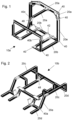
- a frame 10a of a cabin section 10a is shown.
- the cabin section 10a comprises a plurality of profiles, which are designed here as straight extruded profiles, for example.
- the individual profiles 20 are fastened via connecting elements 40, which each connect two or more profiles 20 to one another.
- the profiles can be arranged perpendicularly or at other angles to one another.
- the cabin section 10a forms the driver's cabin of the vehicle frame 10, in which the driver and any passengers sit and steer the vehicle, and has as few profiles 20 as possible in order to minimize the weight of the vehicle frame 10.
- the cabin section 10a can also comprise devices 42 provided for mounting cabin equipment such as passenger seats.
- the cabin section 10a shown has profiles 20a for a roof structure and profiles 20b for a floor structure, whereby in the basic configuration shown, the A-pillars are not yet attached.
- the floor and The roof structures are connected here with vertically aligned or inclined profiles 20e.
- FIG 2 A loading section 10b is shown, which is also formed from floor profiles 20d and upper profiles 20c.
- the loading section 10b forms the rear part of the frame and is intended primarily to serve as a loading area on which equipment, supplies, or people can be transported.
- These profiles 20c, 20d are also connected to vertical or inclined profiles 20e.
- Figure 3 shows a vehicle arrangement according to the invention, which is a combination of the cabin section 10a and the loading section 10b. Most of the profiles 10 are shown only schematically by lines, which are arranged between the connecting elements 40. Furthermore, this vehicle arrangement also includes profiles for a C-pillar 22, which are shown in the Figures 1 and 2 is not shown.
- connecting elements 40 are shown.
- the connecting elements 40 shown are only an exemplary selection and not a complete representation of all the connecting elements 40 used in this embodiment.
- the connecting elements 40 connect two or more profiles 20 at predetermined nodes.
- the connecting elements 40 are detachably attached to the profiles, in particular with screw connections.
- the connecting elements 40 can overlap with the profiles 20 in order to achieve improved rigidity in the nodes. This means that the connecting elements 40 receive the profiles or are at least in laterally contact with the profiles 20 along the longitudinal axis of the profile.
- the screw connections can in principle be provided at these overlaps and inserted into the profiles from the side. For this purpose, drill holes can be provided in the profiles, which can be inserted subsequently in the case of extruded profiles.
- Such lateral screw connections can also be implemented using T-nuts, as will be explained in more detail later with regard to the profiles.
- the connecting elements 40 are fastened to the end face of the profiles 10, as is the case, for example, in the Figures 1-3 shown.
- Connecting elements 40 are shown that can connect one, two, or three profiles 20 together.
- threads can be provided in the drilled holes, for example, or the profiles can be implemented using a screw-nut connection.
- the connecting elements can also have one or more stops against which the profiles 20 can be placed during assembly in order to align the profiles and the connecting elements 40 with each other. This ensures that the holes for screw connections are also precisely aligned with each other.
- the connecting element 40a can, for example, be used in the loading section, where it connects three profiles 20 together.
- the connecting element 40b is used in the cabin section 10a at the front, where it also connects three profiles 20 together.
- the connecting element 40c is arranged in the roof area at the front of the cabin section 10a and connects the profiles 20, which then separate possible windscreens in the finished vehicle.
- Figure 4d The connecting element 40d shown here serves to attach the fastening devices 42 to the vehicle frame 10.
- the connecting elements 40 can be reinforced by lateral support elements 48, which can be attached to the respective connecting element 40 and to the profiles 20 connected thereto.
- the support element 48 is preferably plate-shaped. This increases the rigidity of the connection, which can be further improved by additional reinforcing ribs.
- the connecting elements 40 can also be configured so that additional profiles 20 can be attached to the respective connecting elements 40.
- One example of this is the connecting element 40c, in which lateral boreholes 46 are formed, by means of which another profile 20 can be attached.
- a lateral support element 48 attached there then also has a borehole.
- FIG 5a A roof structure 14 for the loading section 10b is shown.
- the roof structure 14 is formed from individual profiles 10 and connecting elements.
- This roof structure 14 comprises a C-pillar and a D-pillar and preferably covers the entire loading section 10b.
- the loading section 10b can also be extended by additional modules formed from profiles.
- An A-pillar 16 is shown, which can be attached to the central profile 20 on the cabin section 10a.
- the A-pillar makes the cabin section 10a more stable and can better protect the occupants.
- Figure 5c Finally, a vehicle frame 10 is shown in which both the roof structure 14 and the A-pillars 16 have been mounted.
- the profiles 20 are preferably made of aluminum or an aluminum alloy. These figures show profile designs with a core area 22 and groove sections 24.
- the core area 22 is the area of the profile 20 that largely absorbs the forces and moments of loading during vehicle use.
- the groove section is also used to firmly connect the support elements 48 to the profiles 20, but also serves as a simple means of attaching useful attachments such as hooks, eyelets, additional armor plates, transport shelf plates, or any other attachments.
- the core region 22 of the profile 20 is preferably hollow to save weight in the profiles 20.
- the core region can have reinforcing struts 27.
- the groove sections 24 have a groove 25 and adjacent projections 26.
- the groove preferably has undercuts, in particular an undercut parallel to the groove base to create a type of T-slot, so that other profiles 20, utility attachments, or support elements 48 can be attached to the grooves 25 by means of T-nuts 30.
- FIG. 6a-c A first profile 20 is shown, which can be referred to as a T-profile and in which the core area 22 and the groove sections 24 are designed slightly differently.
- Figures 6a-c differs from the Groove section 24 in the width of the groove 25 and in the specific shape of the projections 26.
- each groove section has three grooves 26, which are aligned perpendicular to each other.
- the core area 22 is hollow in all designs and differs in the number and shape of the elongated holes or bores 21. According to the invention, the elongated holes 21 serve to fasten the connecting elements 40.
- FIGs 7a-c An I-profile is shown, which has two groove areas on opposite sides of the core area.
- the grooves of the groove section are also designed as T-slots, which, as with the T-profile, are aligned perpendicular to the adjacent grooves.
- Figure 7a a bore 28 for fastening a connecting element 40 is shown, which, compared to the bores 28 in the Figures 7b and 7c with a smaller diameter.
- each groove section 24 has only one groove 25.
- FIGs 9a and 9c Examples are the profiles from the Figures 6b and 7b shown in an isometric view.
- the core area in Figure 9a has a central elongated hole 21 and reinforcing struts 27 that extend from the elongated hole 21 to the profile walls of the core area 22.
- a slot nut 30 is shown at the intersection in the T-slot, with which a wide variety of attachments, connecting elements 40, and support elements 48 can be attached.
- the slot nut 30 itself has a complementary shape (here a T-shaped cross-section) and an internal thread 31, so that when tightened with a screw, it presses against the undercut of the groove 25 and pulls the element to be tightened against the profile 20, clamping it there.
- Figure 9b then shows the I-profile, in which T-shaped sliding blocks 30 are also provided in the groove 25 of the groove section 24.
- FIG 10 a vehicle assembly with a vehicle frame 10 according to the invention is shown.
- the vehicle assembly has a chassis 12, on which the tires, the drive with engine, transmission, etc. are mounted, and which has a rolling device 8.
- the rolling device 8 is designed here as a normal wheel device, but it is also possible to use a chain drive instead of wheels.
- the vehicle assembly further comprises four seats 11 and a roof hatch 13.
- a machine gun for example, can be attached to the roof hatch or the adjacent profile 20 using the groove sections 24.
- the A-pillar 16 is also attached to the base frame together with folding windshields 15.
- the loading section 10b is provided here without the roof section.
- I-profile as is used, for example, in Figure 9b As shown, floor panels can be attached to the vehicle.
- a first floor panel is then attached to the underside of the profile 20 at the groove 25, in particular a steel floor panel, which can have a wall thickness of 2-5 mm.
- a second floor panel is then attached to the opposite groove 25 of the I-profile, so that the thickness of the I-profile defines a distance between the first and the second floor panel.
- the second floor panel is preferably made of aluminum and ideally has a thicker wall thickness than the first floor panel.
- the first floor panel can absorb the energy of an explosion
- a landmine can be absorbed and absorbed by the first floor panel deforming.
- the distance between the two floor panels prevents the energy from being transferred to the second, spaced-apart floor panel, thus providing optimal protection for the occupants from the deformation of the first floor panel.
- any vehicle frame can be constructed using a modular system.
- add-on A-pillars and roof structures were presented here, which can be attached to the base frame in a modular manner. Since the 20-profiles and 40-connecting elements are detachable, damaged parts can be easily replaced, even if the damage is located on the inner part of the frame.
- a further advantage of 20-profiles manufactured using the extrusion process is that replacement parts can be cut from the profiles on hand using simple tools.
Landscapes
- Engineering & Computer Science (AREA)
- Chemical & Material Sciences (AREA)
- Combustion & Propulsion (AREA)
- Transportation (AREA)
- Mechanical Engineering (AREA)
- General Engineering & Computer Science (AREA)
- Body Structure For Vehicles (AREA)
Description
- Die Erfindung betrifft ein Fahrzeuggestell, das modular aufgebaut ist, sowie ein Fahrzeug mit einem solchen Fahrzeuggestell, insbesondere für die Nutzung in Kampfeinsätzen.
- Fahrzeuge, die in Kampfgebieten eingesetzt werden, müssen eine Vielzahl von unterschiedlichen Anforderungen erfüllen. Zu solchen Anforderungen gehören unter anderem der Truppentransport, das Bereitstellen von Sanitätseinrichtungen, Transport von schwerem Gerät oder der Einsatz als leichtes Kampffahrzeug. Aufgrund dieser unterschiedlichen Anforderungen werden solche Einsatzfahrzeuge in einer Art Basisausführung gebaut und dann jeweils entsprechend den Anforderungen weitergebildet. So wird dann beispielsweise ein Basisfahrzeug durch eine A-Säule mit einem Maschinengewehraufsatz ergänzt, oder das Heck durch einen Aufsatz für eine Plane und mit Bänken als Truppentransporter ausgebildet. Diese Anbauten sind üblicherweise einfache Stahlrohre und werden an das Basisfahrzeug fest verschweißt, so dass die Anbauten bei Belastung nicht wegbrechen oder abfallen können. Wenn also ein Basisfahrzeug einmal für einen bestimmten Zweck weitergebildet wurde, ist es in der Regel unmöglich dieses Fahrzeug umzuwidmen.
- Die
DE 10 2017 011 838 A1 offenbart eine Kraftfahrzeugkarosseriestruktur, mit einem Tragrahmen, wobei der Tragrahmen aus einer Mehrzahl von Strangpressprofilen zusammengebaut ist. Die Strangpressprofile haben zumindest teilweise Aufnahmen zur Aufnahme von Flächenelementen, wobei die Flächenelemente in den Tragrahmen eingesteckt und daran festgelegt sind. Die Strangpressprofile werden über Eckverbinder miteinander verbunden. - Die
DE 197 35 594 A1 offenbart eine Einrichtung zur Sicherung der Verfügbarkeit von militärischen Fahrzeugen, insbesondere von gepanzerten Rad- und Kettenfahrzeugen, vorzugsweise zum Schutz vor Mineneinwirkung, dadurch gekennzeichnet, daß die Einrichtung als Schutzschild unter dem Fahrzeug befestigbar ist und aus einer horizontal angeordneten Trägerplatte und im Winkel zur Trägerplatte verlaufenden, auf die Fahrzeugunterseite gerichteten Streben besteht. - Aufgabe der Erfindung ist es daher, ein Grundgerüst für ein Kampfeinsatzfahrzeug bereitzustellen, das einfach für unterschiedliche Aufgaben aufgerüstet, aber auch umgerüstet werden kann. Diese Aufgabe wird gelöst durch einen Fahrzeugrahmen nach Anspruch 1. Weitere, die Erfindung ausgestaltende Merkmale sind in den Unteransprüchen enthalten.
- Eine erfindungsgemäße modular aufbaubare Fahrzeuganordnung umfasst einen Fahrzeugrahmen, wobei der Fahrzeugrahmen eine Vielzahl von Profilen und eine Vielzahl von Verbindungselementen aufweist, wobei jedes Profil mit einem Profilquerschnitt und einer Profillängsachse ausgebildet ist, und wobei die Profile mit den Verbindungselementen lösbar, insbesondere mit einer Schraubverbindung, miteinander verbunden sind, wobei die Profile (20) in ihrem Innern Langlöcher (21, 28) entlang der Profillängsachse zum Befestigen von Verbindungselementen (40) umfassen und die Verbindungselemente (40) mittels der Langlöcher (21, 28) an den Profilen (20) befestigt sind.
- Durch die Verwendung von Verbindungselementen und Profilen können unterschiedlichste aber demontierbare Anbauten an einen Fahrzeugrahmen angebracht werden und die Flexibilität der Fahrzeuganordnung wird durch die Möglichkeit Erweiterungen wieder zu demontieren außerordentlich gesteigert. Die Befestigung geschieht bevorzugt mittels Schrauben und schon in die Profile eingebrachte Gewinde, oder über Schrauben und Muttern. Vorzugsweise sind die Profile als Strangpressprofile ausgebildet. Solche Strangpressprofile sind einfach herzustellen und können gleichzeitig eine ausreichend komplexes Profil und Festigkeit haben, um alle Anforderungen für die Fahrzeuganordnung zu erfüllen. Die Strangpressprofile sind vorzugsweise aus Aluminium oder einer Aluminiumlegierung gefertigt. Dadurch wird das Gewicht des Fahrzeugrahmens weiter reduziert.
- Ein Profilquerschnitt weist vorteilhafterweise einen Kernbereich und zumindest einen Nutabschnitt auf, wobei der Nutabschnitt an den Kernbereich angrenzt. So sind die Profile kompakt ausgebildet und gleichzeitig flexibel einsetzbar. Ein Nutabschnitt weist jeweils zumindest eine Nut mit einer Hinterschneidung zum Aufnehmen und Halten von Nutzanbauten auf. Dadurch kann jedes Profil auf den Einsatzzweck hin optimiert werden. Das Profil kann eine Vielzahl von Nutabschnitten aufweisen, die umlaufend um die Längsachse der Profile um den Kernbereich herum angeordnet sind. Dadurch bleibt auch bei vielen Nutabschnitten das Profil kompakt und platzsparend. Der Kernbereich des Profils ist vorzugsweise hohl ausgebildet und kann insbesondere eine oder mehrere Verstärkungen aufweisen. Dadurch weist das Profil ein geringes Gewicht auf, behält aber insbesondere auch die notwendige Festigkeit.
- Die tragenden Bauteile des Fahrzeugrahmens, also alle Elemente, die fahrbedingte Kräfte übertragen, sind bevorzugt ausschließlich aus Profilen und Verbindungselementen aufgebaut. Dadurch kann die Einsatzfähigkeit eines Fahrzeugs sichergestellt werden, da alle beschädigten Profile und Verbindungselemente einfach ersetzt werden können. Die Verbindung der Profile mittels der Verbindungselemente wird vorteilhafterweise durch Unterstützungselemente verstärkt. Die Unterstützungselemente sind einfach zu montieren und verbessern die Festigkeit an den kritischen Knotenpunkten.
- Die Profile umfassen Langlöcher entlang der Profillängsachse zum Befestigen der Verbindungselemente. Insbesondere weisen die Langlöcher selbst ein Gewinde auf oder sie werden mit einem Gewinderohr bestückt, um das Befestigen mittels Schauben zu ermöglichen. Dadurch ist die Ausrichtung der einzelnen Profile in Bezug auf das Verbindungselement klar festgelegt während das Profil gleichzeitig kompakt bleibt, da die Langlöcher erfindungsgemäß im inneren des Profils, insbesondere im Kernbereich ausgebildet sind.
- Ferner umfasst die Fahrzeuganordnung eine erste Bodenplatte und eine zweite Bodenplatte, wobei die erste und zweite Bodenplatte voneinander beabstandet sind und insbesondere am gleichen Profil befestigt sind. Dadurch wird der Personenschutz im inneren des Fahrzeugs verbessert. Die erste Bodenplatte ist unter der zweiten Bodenplatte angeordnet und vorzugsweise aus Stahl, während die zweite bevorzugt aus Aluminium oder einer Aluminiumlegierung hergestellt ist. Die zweite Bodenplatte weist bevorzugt eine größere Wandstärke als die erste Bodenplatte auf.
- Die Verbindungselemente weisen bevorzugt Anschläge für die Ausrichtung der Profile auf. Dadurch kann sichergestellt werden, dass die Bohrungen der Profile und der Verbindungselemente übereinstimmen und die Montage und das Befestigen der Profile an den Verbindungselementen erleichtert werden.
- Eine erfindungsgemäße Fahrzeuganordnung umfasst vorzugsweise ferner ein Fahrgestell, wobei das Fahrgestell mit dem Fahrzeugrahmen über Lagerelemente verbunden ist und wobei das Fahrgestell unterhalb des Fahrzeugrahmens angeordnet ist. Das Fahrgestell (12) weist eine erste Bodenplatte und der Fahrzeugrahmen eine zweite Bodenplatte auf, wobei die erste und zweite Bodenplatte voneinander beabstandet sind. Das Fahrgestell kann außerdem zumindest einen Antrieb und eine Rolleinrichtung aufweisen.
-
-
Figur 1 zeigt einen Rahmen mit Profilen und Verbindungselementen, der für einen Kabinenabschnitt vorgesehen ist; -
Figur 2 zeigt einen Rahmen mit Profilen und Verbindungselementen, der für einen Lastabschnitt vorgesehen ist; -
Figur 3 zeigt einen erfindungsgemäßen Fahrzeugrahmen, der die Rahmen aus denFiguren 1 und 2 kombiniert und bei dem die Profile nur schematisch dargestellt sind; -
Figuren 4a-d zeigen verschiedene Ausführungsformen eines Verbindungselements zum Verbinden zweier oder mehrerer Profile; -
Figur 5a zeigt eine Erweiterung des Fahrzeugrahmens für eine Abdeckung des Ladeabschnitts; -
Figur 5b zeigt eine Erweiterung des Fahrzeugrahmens für eine A-Säule; -
Figur 5c zeigt einen Fahrzeugrahmen mit montierten Erweiterungen ausFigur 5a und 5b ; -
Figuren 6a-c zeigt unterschiedliche Ausführungsformen eines ersten verstärkten Profils mit einem Kernbereich und drei Nutabschnitten; -
Figuren 7a-c zeigen unterschiedliche Ausführungsformen eines zweiten Profils mit einem Kernbereich und zwei Nutabschnitten; -
Figuren 8a-c zeigen unterschiedliche Ausführungsformen eines dritten Profils mit einem Kernbereich und vier Nutabschnitten; -
Figuren 9a undb zeigen eine isometrische Ansicht zweier Profile; und -
Figur 10 zeigt ein Fahrzeug mit einem erfindungsgemäßen Fahrzeugrahmen und einem Fahrgestell. - Ein erfindungsgemäßer Fahrzeugrahmen 10 weist Profile 20 und Verbindungselemente 40 auf. Grundsätzlich können die Profile 20 beliebig ausgebildet sein, so dass beispielsweise ein Profil 20 gebogen sein kann oder auch mehrere Profile 20 verschweißt sein können um einen Basisrahmen bereitzustellen. Im Prinzip kann der Basisrahmen also durch Verschweißen oder ähnliches einstückig ausgebildet sein. Wichtig ist, dass der Basisrahmen auch Verbindungselemente 40 aufweist, mittels der die Erweiterungen für den Fahrzeugrahmen 10 an den Basisrahmen angebracht werden können. Es ist jedoch bevorzugt, dass der gesamte Fahrzeugrahmen 10 aus einzelnen, mittels Verbindungselementen 40 verbundenen Profilen ausgebildet ist. Bevorzugt sind die Profile auch nicht selbst gebogen, sondern gerade ausgebildet. Vorgesehene Krümmungen werden dann mit entsprechenden Verbindungselementen 40 verwirklicht, wie nachfolgend noch erläutert wird.
- In
Figur 1 ist ein Rahmen 10a eines Kabinenabschnitts 10a dargestellt. Der Kabinenabschnitt 10a umfasst eine Vielzahl von Profilen, die hier beispielhaft als gerade Strangpressprofile ausgebildet sind. Die einzelnen Profile 20 sind über Verbindungselementen 40 befestigt, die jeweils zwei oder mehrere Profile 20 miteinander verbinden. Die Profile können senkrecht oder in anderen Winkeln zueinander angeordnet sein. Der Kabinenabschnitt 10a bildet die Fahrkabine des Fahrzeugrahmens 10, in dem der Fahrer und mögliche Beifahrer sitzen und das Fahrzeug steuern und weist so wenige Profile 20 wie möglich auf, um das Gewicht des Fahrzeugrahmens 10 zu minimieren. Der Kabinenabschnitt 10a kann außer den Verbindungselementen 40 auch Vorrichtungen 42 umfassen, die für das montieren von Kabineneinrichtung wie beispielsweise Personensitze vorgesehen sind. Der gezeigte Kabinenabschnitt 10a weist Profile 20a für eine Dachkonstruktion und Profile 20b für eine Bodenkonstruktion auf, wobei in der gezeigten Basisausstattung die A-Säulen noch nicht angebaut sind. Die Boden-und die Dachkonstruktion sind hier mit vertikal ausgerichteten oder geneigten Profilen 20e miteinander verbunden. - In
Figur 2 ist ein Ladeabschnitt 10b dargestellt, der auch aus Bodenprofilen 20d und aus oberen Profilen 20c ausgebildet ist. Der Ladeabschnitt 10b formt den hinteren Teil des Rahmens und soll grundsätzlich als Ladefläche dienen, auf der Ausrüstung, Vorräte oder Personen transportiert werden können. Diese Profile 20c, 20d sind ebenfalls mit vertikalen oder geneigten Profilen 20e verbunden.Figur 3 zeigt eine erfindungsgemäße Fahrzeuganordnung, die eine Kombination des Kabinenabschnitts 10a und des Ladeabschnitts 10b ist. Die meisten Profile 10 sind hier nur schematisch durch Striche dargestellt, die zwischen den Verbindungselementen 40 angeordnet sind. Ferner umfasst diese Fahrzeuganordnung auch Profile für eine C-Säule 22, die in denFiguren 1 und 2 nicht dargestellt ist. - In den
Figuren 4a-d sind verschiedene Verbindungselemente 40 gezeigt. Die gezeigten Verbindungselemente 40 sind nur eine beispielhafte Auswahl und keine abschließende Darstellung aller in dieser Ausführungsform verwendeten Verbindungselemente 40. Wie oben erwähnt verbinden die Verbindungselemente 40 zwei oder mehrere Profile 20 an vorbestimmten Knotenpunkten. Die Verbindungselemente 40 werden lösbar an den Profilen angebracht, insbesondere mit Schraubverbindungen. Die Verbindungselemente 40 können mit den Profilen 20 überlappen, um eine verbesserte Steifigkeit in den Knoten zu erhalten. Das heißt, dass die Verbindungselemente 40 die Profile aufnehmen oder zumindest seitlich entlang der Profillängsachse mit den Profilen 20 in Kontakt stehen. Die Schraubverbindungen können prinzipiell an diesen Überlappungen vorgesehen sein und von der Seite in die Profile eingebracht werden. Dafür können in den Profilen Bohrlöcher vorgesehen sein, die im Falle von Strangpressprofilen nachträglich eingebracht werden können. Solche seitlichen Schraubverbindungen können aber auch über Nutensteine ausgeführt sein, wie später in Bezug auf die Profile noch detailliert ausgeführt wird. Erfindungsgemäß ist jedoch vorgesehen, dass die Verbindungselemente 40 an der Stirnseite der Profile 10 befestigt werden, wie es beispielsweise in denFiguren 1-3 gezeigt ist. In denFiguren 4a bis 4c sind Verbindungselemente 40 dargestellt, die ein, zwei oder drei Profile 20 miteinander verbinden können. Für Schraubverbindungen können bspw. in den Bohrlöchern Gewinde vorgesehen sein oder die Profile werden über eine Schrauben-Mutter-Verbindung verwirklicht. Ferner können die Verbindungselemente auch einen oder mehrere Anschläge aufweisen, gegen die die Profile 20 bei der Montage angelegt werden können, um die Profile und die Verbindungselemente 40 zueinander auszurichten. Dadurch liegen dann auch die Bohrungen von Schraubverbindungen an exakten zueinander ausgerichteten Positionen. - Das Verbindungselement 40a kann beispielsweise im Ladeabschnitt eingesetzt werden und verbindet dort drei Profile 20 miteinander. Das Verbindungselement 40b wird im Kabinenabschnitt 10a an der Vorderseite verwendet, wo es ebenfalls drei Profile 20 miteinander verbindet. Das Verbindungselement 40c ist am Dachbereich an der Vorderseite des Kabinenabschnitts 10a angeordnet und verbindet die Profile 20, die dann im fertigen Fahrzeug mögliche Frontscheiben trennen. Das in
Figur 4d gezeigte Verbindungselement 40d dient hier zum Anbringen der Befestigungsvorrichtungen 42 an dem Fahrzeugrahmen 10. - Die Verbindungselemente 40 können durch seitliche Unterstützungselemente 48 verstärkt werden, die an das jeweilige Verbindungselement 40 und an die damit verbundenen Profile 20 angebracht werden können. Das Unterstützungselement 48 ist bevorzugt plattenförmig ausgebildet. Dadurch wird die Steifigkeit der Verbindung erhöht, die durch zusätzliche Verstärkungsrippen noch einmal verbessert werden kann. Die Verbindungselemente 40 können ferner auch so eingerichtet sein, so dass weitere Profile 20 an den jeweiligen Verbindungselementen 40 befestigt werden können. Als ein Beispiel hierfür kann das Verbindungselemente 40c dienen, in dem seitliche Bohrlöcher 46 ausgebildet sind, mittels der ein weiteres Profil 20 befestigt werden kann. Ein dort angebrachtes seitliches Unterstützungselement 48 weist dann ebenfalls ein Bohrloch auf.
- In
Figur 5a ist ein Dachaufbau 14 für den Ladeabschnitt 10b dargestellt. Der Dachaufbau 14 ist aus einzelnen Profilen 10 und Verbindungselementen ausgebildet. Dieser Dachaufbau 14 umfasst eine C- und eine D-Säule, und bedeckt vorzugsweise den gesamten Ladeabschnitt 10b. Der Ladeabschnitt 10b kann ebenfalls durch solche durch Profile ausgebildeten Zusatzmodule verlängert werden. InFigur 5b ist eine A-Säule 16 dargestellt, die an das mittlere Profil 20 am Kabinenabschnitt 10a angebracht werden kann. Durch die A-Säule ist der Kabinenabschnitt 10a stabiler und kann die Insassen besser schützen. inFigur 5c ist schließlich ein Fahrzeugrahmen 10 dargestellt, bei dem sowohl der Dachaufbau 14 als auch die A-Säulen 16 montiert wurden. - In den
Figuren 6-8 sind verschiedene Profilquerschnitte dargestellt für drei unterschiedliche Profilausführungen. Die Profile 20 sind vorzugsweise aus Aluminium oder einer Aluminiumlegierung hergestellt. In diesen Figuren sind Profilausführungen mit einem Kernbereich 22 und Nutabschnitten 24 gezeigt. Der Kernbereich 22 ist der Bereich des Profils 20, der die Kräfte und Momente der Belastung im Einsatz des Fahrzeugs größtenteils aufnimmt. Der Nutabschnitt wird allerdings ebenfalls dazu verwendet, die Unterstützungselemente 48 fest mit den Profilen 20 zu verbinden, dient aber auch einer einfachen Befestigungsmöglichkeit von Nutzanbauten wie beispielsweise Haken, Ösen, zusätzlichen Panzerplatten, Transportregalplatten oder beliebige andere Anbauten. - Der Kernbereich 22 des Profils 20 ist vorzugsweise hohl ausgebildet, um Gewicht bei den Profilen 20 zu sparen. Der Kernbereich kann Verstärkungsstreben 27 aufweisen. Die Nutabschnitte 24 weisen eine Nut 25 auf und angrenzende Vorsprünge 26 auf. Die Nut weist vorzugsweise Hinterschneidungen auf, insbesondere eine zum Nutgrund parallele Hinterschneidung um eine Art T-Nut zu erzeugen, so dass mittels Nutensteinen 30 andere Profile 20, Nutzanbauten oder Unterstützungselemente 48 an den Nuten 25 befestigt werden können.
- In den
Figuren 6a-c ist ein erstes Profil 20 abgebildet, die als T-Profile bezeichnet werden können und bei denen der Kernbereich 22 und die Nutabschnitte 24 leicht unterschiedlich ausgebildet sind. In denFiguren 6a-c unterscheidet sich der Nutabschnitt 24 in der Breite der Nut 25 und in der konkreten Form der Vorsprünge 26. Hier weist jeder Nutabschnitt drei Nuten 26 auf, die zueinander senkrecht ausgerichtet sind. Der Kernbereich 22 ist bei allen Ausführungen hohl ausgebildet und unterscheidet sich in der Anzahl und Form der Langlöcher oder Bohrungen 21. Die Langlöcher 21 dienen erfindungsgemäß zum Befestigen der Verbindungselemente 40. Dazu wird in die Langlöcher 21 ein Gewinde eingeschnitten oder ein Gewinderohr eingesetzt, welches in der Regel aus einem härteren Material (z.B. Stahl, Edelstahl) ausgebildet ist, als die Profile. InFigur 6a sind drei Langlöcher 21 vorgesehen, die jeweils in durch Streben 27 miteinander und mit den Wänden des Kernbereichs 22 verbunden sind. Dadurch kann das entsprechende Verbindungselement 40 besser befestigt werden.Figur 6b zeigt eine Ausführungsform, bei der nur ein Langloch 21 vorgesehen ist, der über Streben gehalten wird. Hier ist das Langloch 21 mit einem größeren Innendurchmesser ausgebildet, was für die Verwendung eines Gewinderohrs gedacht ist. Und inFigur 6c ist eine bevorzugte Ausführungsform dargestellt, bei der ein Langloch 21 vorgesehen ist, der auf einer Seite offen ausgeführt ist. Das ist zum einen für ein im Strangpressverfahren hergestelltes Profil 20 eine besser geeignete Form, zum anderen lassen sich in ein offenes Langloch 21 die oben erwähnten Gewinderohre einfacher einbringen. - In den
Figuren 7a-c ist ein I-Profil dargestellt, das zwei Nutebereiche auf gegenüberliegenden Seiten des Kernbereichs aufweist. Die Nuten des Nutabschnitts sind hier ebenfalls als T-Nuten ausgebildet, die wie bei dem T-Profil senkrecht zu den jeweils benachbarten Nuten ausgerichtet sind. InFigur 7a ist eine Bohrung 28 zur Befestigung eines Verbindungselements 40 gezeigt, die im Vergleich zu den Bohrungen 28 in denFiguren 7b und 7c mit einem geringeren Durchmesser ausgeführt ist. - Und in den
Figuren 8a-c ist ein Kernbereich 22 mit vier Nutabschnitten 24 dargestellt, die alle umfänglich um den Kernbereich angeordnet sind. Dieser Kernbereich 22 ist schmaler als der aus denFiguren 6 und 7 . Daher weist hier auch jeder Nutabschnitt 24 nur eine Nut 25 auf. - In den
Figuren 9a und 9c sind beispielhaft die Profile aus denFiguren 6b und 7b in einer isometrischen Ansicht gezeigt. Der Kernbereich inFigur 9a weist ein mittiges Langloch 21 und Verstärkungsstreben 27 auf, die sich vom Langloch 21 zu den Profilwänden des Kernbereichs 22 erstrecken. An der Schnittfläche in der T-Nut ist ein Nutenstein 30 dargestellt mit dem unterschiedlichste Nutzanbauten, Verbindungselemente 40 und Unterstützungselemente 48 angebracht werden können. Dazu weist der Nutenstein 30 selbst eine komplementäre Gestalt (hier einen T-förmigen Querschnitt) und ein Innengewinde 31 auf, so dass er beim Festziehen mit einer Schraube gegen die Hinterschneidung der Nut 25 drückt und das Festzuziehende Element gegen das Profil 20 zieht und dort festklemmt.Figur 9b zeigt dann das I-Profil, in dem ebenfalls t-förmige Nutensteine 30 in der Nut 25 des Nutabschnitts 24 vorgesehen sind. - In
Figur 10 ist ein schließlich eine Fahrzeuganordnung mit einem erfindungsgemäßen Fahrzeugrahmen 10. Die Fahrzeuganordnung weist ein Fahrgestell 12 auf, an dem die Reifen, der Antrieb mit Motor, Getriebe, usw. gelagert sind und die eine Rolleinrichtung 8 aufweist. Die Rolleinrichtung 8 ist hier als eine normale Radeinrichtung ausgebildet, aber es ist ebenfalls möglich, dass statt Rädern ein Kettenantrieb verwendet werden kann. In der gezeigten Ausführungsform umfasst die Fahrzeuganordnung ferner auch vier Sitze 11 und eine Dachluke 13. An der Dachluke bzw. dem benachbarten Profil 20 kann mit Hilfe der Nutabschnitte 24 beispielsweise ein Maschinengewehr befestigt werden. Die A-Säule 16 ist ebenfalls zusammen mit klappbaren Windschutzscheiben 15 am Basisrahmen befestigt. Der Ladeabschnitt 10b ist hier dagegen ohne den Dachabschnitt vorgesehen. Mit einem I-Profil wie es bspw. inFigur 9b dargestellt ist, können Bodenbleche an dem Fahrzeug befestigt werden. An der Unterseite des Profils 20 wird dann ein erstes Bodenblech an der Nut 25 befestigt, insbesondere ein Bodenblech aus Stahl, das 2-5mm Wandstärke aufweisen kann. An der gegenüberliegenden Nut 25 des I-Profils wird dann ein zweites Bodenblech befestigt, so dass die Dicke des I-Profils einen Abstand zwischen dem ersten und dem zweiten Bodenblech definiert. Das zweite Bodenblech ist vorzugsweise aus Aluminium ausgebildet und weist idealerweise eine dickere Wandstärke auf, als das erste Bodenblech. So kann das erste Bodenblech die Energie einer Explosion beispielsweise einer Landmine aufnehmen und abfangen, indem sich das erste Bodenblech verformt. Durch den Abstand der beiden Bodenbleche wird aber vermieden, dass die Energie an das zweite, beabstandete Bodenblech weitergeleitet wird, so dass die Insassen vor der Verformung im ersten Bodenblech optimal geschützt sind. - Mit den hier vorgestellten Profilen 20 und Verbindungselementen 40 können nahezu beliebige Fahrzeugrahmen im Baukastenprinzip erstellt werden. Konkret wurden hier ergänzbare A-Säulen und Dachaufbauten vorgestellt, die modular an den Basisrahmen angebracht werden können. Da die Befestigung der Profile 20 und Verbindungselemente 40 lösbar ausgebildet sind, können beschädigte Teile einfach ersetzt werden, selbst wenn die Beschädigung am inneren Teil des Rahmens vorhanden ist. Ein weiterer Vorteil ist bei Profilen 20 die im Strangpressverfahren hergestellt sind, dass Ersatzteile mit einfachem Werkzeug aus mitgeführter Profilmeterware zugeschnitten werden können.
-
- 8
- Rolleinrichtung
- 10
- Fahrzeugrahmen
- 10a
- Kabinenabschnitt
- 10b
- Ladeabschnitt
- 12
- Fahrgestell
- 13
- Dachluke
- 14
- Dachaufbau
- 15
- klappbare Windschutzscheibe
- 16
- A-Säule
- 20
- Profil
- 20a
- Dachprofil
- 20b, 20d
- Bodenprofil
- 20c
- oberes Profil
- 20e
- vertikale Profile
- 21
- Langloch
- 22
- Kernbereich
- 24
- Nutabschnitt
- 25
- Nut
- 26
- Vorsprung
- 27
- Verstärkungsstrebe
- 28
- Bohrung
- 30
- Nutenstein
- 31
- Gewindebohrung
- 40
- Verbindungselement
- 42
- Vorrichtungen
- 44
- Bohrloch
- 46
- seitliches Bohrloch
- 48
- Unterstützungselemente
Claims (12)
- Modular aufbaubare Fahrzeuganordnung umfassend einen Fahrzeugrahmen (10), wobei der Fahrzeugrahmen (10) eine Vielzahl von Profilen (20) und eine Vielzahl von Verbindungselementen (40) aufweist, wobei jedes Profil (20) mit einem Profilquerschnitt und einer Profillängsachse ausgebildet ist, und wobei die Profile (20) mit den Verbindungselementen (40) lösbar miteinander verbunden sind
dadurch gekennzeichnet, dass
die Profile (20) in ihrem Innern Langlöcher (21, 28) entlang der Profillängsachse zum Befestigen von Verbindungselementen (40) umfassen und die Verbindungselemente (40) mittels der Langlöcher (21, 28) an den Profilen (20) befestigt sind. - Fahrzeuganordnung nach Anspruch 1, wobei ein Profilquerschnitt einen Kernbereich (22) und zumindest einen Nutabschnitt (24) aufweist, und wobei der Nutabschnitt (24) an den Kernbereich (22) angrenzt.
- Fahrzeuganordnung nach Anspruch 2, wobei der Nutabschnitt (24) zumindest eine Nut (25) mit einer Hinterschneidung zum Aufnehmen und Halten von Nutzanbauten aufweist.
- Fahrzeuganordnung nach Anspruch 2 oder 3, wobei das Profil (20) eine Vielzahl von Nutabschnitten (24) aufweist, die umlaufend um die Längsachse der Profile (20) um den Kernbereich (22) herum angeordnet sind.
- Fahrzeuganordnung nach einem der Ansprüche 2 bis 4, wobei der Kernbereich (22) hohl ausgebildet ist und insbesondere eine oder mehrere Verstärkungen aufweist.
- Fahrzeuganordnung nach einem der vorhergehenden Ansprüche, wobei der Fahrzeugrahmen (10) ausschließlich aus Profilen (20) und Verbindungselementen (40) aufgebaut ist.
- Fahrzeuganordnung nach einem der vorhergehenden Ansprüche, wobei die Verbindung der Profile (20) mittels der Verbindungselemente (40) durch Unterstützungselemente (48) verstärkt wird.
- Fahrzeuganordnung nach einem der vorhergehenden Ansprüche, ferner umfassend eine erste Bodenplatte und eine zweite Bodenplatte, wobei die erste und zweite Bodenplatte voneinander beabstandet sind.
- Fahrzeuganordnung nach Anspruch 8, bei der die erste und zweite Bodenplatte am gleichen Profil (20) befestigt sind.
- Fahrzeuganordnung nach einem der vorhergehenden Ansprüche, bei der die Verbindungselemente (40) Anschläge für die Ausrichtung der Profile (20) aufweisen.
- Fahrzeuganordnung nach einem der vorhergehenden Ansprüche, ferner umfassend ein Fahrgestell (12), wobei das Fahrgestell (12) mit dem Fahrzeugrahmen (10) über Lagerelemente verbunden ist, wobei das Fahrgestell (12) unterhalb des Fahrzeugrahmens (10) angeordnet ist.
- Fahrzeuganordnung nach Anspruch 11, wobei das Fahrgestell (12) ferner zumindest einen Antrieb und eine Rolleinrichtung (8) aufweist.
Priority Applications (5)
| Application Number | Priority Date | Filing Date | Title |
|---|---|---|---|
| ES21162397T ES3035665T3 (en) | 2021-03-12 | 2021-03-12 | Modular structure for vehicle |
| HUE21162397A HUE072208T2 (hu) | 2021-03-12 | 2021-03-12 | Modulárisan felépíthetõ jármûváz |
| EP21162397.0A EP4056943B1 (de) | 2021-03-12 | 2021-03-12 | Modular aufbaubares fahrzeuggestell |
| PL21162397.0T PL4056943T3 (pl) | 2021-03-12 | 2021-03-12 | Modułowa konstrukcja dla pojazdu |
| HRP20250880TT HRP20250880T1 (hr) | 2021-03-12 | 2021-03-12 | Modularna struktura za vozilo |
Applications Claiming Priority (1)
| Application Number | Priority Date | Filing Date | Title |
|---|---|---|---|
| EP21162397.0A EP4056943B1 (de) | 2021-03-12 | 2021-03-12 | Modular aufbaubares fahrzeuggestell |
Publications (3)
| Publication Number | Publication Date |
|---|---|
| EP4056943A1 EP4056943A1 (de) | 2022-09-14 |
| EP4056943B1 true EP4056943B1 (de) | 2025-05-21 |
| EP4056943C0 EP4056943C0 (de) | 2025-05-21 |
Family
ID=74873644
Family Applications (1)
| Application Number | Title | Priority Date | Filing Date |
|---|---|---|---|
| EP21162397.0A Active EP4056943B1 (de) | 2021-03-12 | 2021-03-12 | Modular aufbaubares fahrzeuggestell |
Country Status (5)
| Country | Link |
|---|---|
| EP (1) | EP4056943B1 (de) |
| ES (1) | ES3035665T3 (de) |
| HR (1) | HRP20250880T1 (de) |
| HU (1) | HUE072208T2 (de) |
| PL (1) | PL4056943T3 (de) |
Citations (8)
| Publication number | Priority date | Publication date | Assignee | Title |
|---|---|---|---|---|
| EP0294782A2 (de) | 1987-06-10 | 1988-12-14 | Dornier Gmbh | Mehrzweckpalette |
| DE19735594A1 (de) | 1997-08-15 | 1999-02-25 | Henschel Wehrtechnik Gmbh | Einrichtung zur Sicherung der Verfügbarkeit von militärischen Fahrzeugen, insbesondere von gepanzerten Rad- und Kettenfahrzeugen |
| DE202007002604U1 (de) | 2006-12-22 | 2007-04-26 | Holscher, Winfried K.W. | Profilverbinder sowie Profilverbund |
| CN105015684A (zh) | 2014-04-28 | 2015-11-04 | 刘岗 | 侧面具有钩槽卡合机构的自行车车架构件及配件系统 |
| WO2016003982A1 (en) | 2014-07-02 | 2016-01-07 | Divergent Technologies, Inc. | Systems and methods for fabricating joint members |
| EP2698274B1 (de) | 2009-06-15 | 2017-05-03 | Polaris Industries Inc. | Zweisitzer |
| DE102017011838A1 (de) | 2017-12-21 | 2018-06-28 | Daimler Ag | Kraftfahrzeugkarosseriestruktur sowie Kraftfahrzeug |
| WO2020141405A1 (en) | 2018-12-31 | 2020-07-09 | TRONCHETTI, Matteo | System for producing a containing structure for vehicles with cabs or the like, method and vehicle obtained with said structure |
Family Cites Families (2)
| Publication number | Priority date | Publication date | Assignee | Title |
|---|---|---|---|---|
| CH627982A5 (de) * | 1977-11-03 | 1982-02-15 | Alusuisse | Wagenkastenkonstruktion fuer strassen- oder schienenfahrzeuge zur personenbefoerderung. |
| DE3333038A1 (de) * | 1983-09-13 | 1985-03-21 | Gebr. Bachert GmbH & Co Feuerwehrgerätefabriken, 7107 Bad Friedrichshall | Profilsystem fuer die skelettkonstruktion von fahrzeugaufbauten |
-
2021
- 2021-03-12 EP EP21162397.0A patent/EP4056943B1/de active Active
- 2021-03-12 HR HRP20250880TT patent/HRP20250880T1/hr unknown
- 2021-03-12 PL PL21162397.0T patent/PL4056943T3/pl unknown
- 2021-03-12 ES ES21162397T patent/ES3035665T3/es active Active
- 2021-03-12 HU HUE21162397A patent/HUE072208T2/hu unknown
Patent Citations (8)
| Publication number | Priority date | Publication date | Assignee | Title |
|---|---|---|---|---|
| EP0294782A2 (de) | 1987-06-10 | 1988-12-14 | Dornier Gmbh | Mehrzweckpalette |
| DE19735594A1 (de) | 1997-08-15 | 1999-02-25 | Henschel Wehrtechnik Gmbh | Einrichtung zur Sicherung der Verfügbarkeit von militärischen Fahrzeugen, insbesondere von gepanzerten Rad- und Kettenfahrzeugen |
| DE202007002604U1 (de) | 2006-12-22 | 2007-04-26 | Holscher, Winfried K.W. | Profilverbinder sowie Profilverbund |
| EP2698274B1 (de) | 2009-06-15 | 2017-05-03 | Polaris Industries Inc. | Zweisitzer |
| CN105015684A (zh) | 2014-04-28 | 2015-11-04 | 刘岗 | 侧面具有钩槽卡合机构的自行车车架构件及配件系统 |
| WO2016003982A1 (en) | 2014-07-02 | 2016-01-07 | Divergent Technologies, Inc. | Systems and methods for fabricating joint members |
| DE102017011838A1 (de) | 2017-12-21 | 2018-06-28 | Daimler Ag | Kraftfahrzeugkarosseriestruktur sowie Kraftfahrzeug |
| WO2020141405A1 (en) | 2018-12-31 | 2020-07-09 | TRONCHETTI, Matteo | System for producing a containing structure for vehicles with cabs or the like, method and vehicle obtained with said structure |
Also Published As
| Publication number | Publication date |
|---|---|
| HRP20250880T1 (hr) | 2025-09-26 |
| HUE072208T2 (hu) | 2025-11-28 |
| ES3035665T3 (en) | 2025-09-08 |
| EP4056943C0 (de) | 2025-05-21 |
| PL4056943T3 (pl) | 2025-09-22 |
| EP4056943A1 (de) | 2022-09-14 |
Similar Documents
| Publication | Publication Date | Title |
|---|---|---|
| EP3710342B1 (de) | Seitenschwelleranordnung einer karosserie eines elektrisch betreibbaren kraftwagens | |
| DE102015111749A1 (de) | Batterieeinrichtung und Verfahren | |
| DE602005003719T2 (de) | Flugzeugcockpitboden | |
| EP3049311B1 (de) | Instrumententafelquerträger für ein fahrzeug sowie fahrzeug mit einem solchen instrumententafelquerträger | |
| DE102012021857B4 (de) | Schutzanordnung zum Schutz einer Fahrzeugbatterie in einer Fahrzeugkarosserie | |
| EP3601017B1 (de) | Kabinenmodul sowie damit ausgestattetes kraftfahrzeug | |
| EP0561816B1 (de) | Verstärkung eines blechteils, insbesondere an einer fahrzeugkarosserie | |
| EP0791528B1 (de) | Kastenaufbau für ein Nutzfahrzeug , insbesondere ein Einsatzfahrzeug , wie ein Feuerwehrfahrzeug | |
| DE102005004780B3 (de) | Deformationselement für ein Kraftfahrzeug | |
| EP4056943B1 (de) | Modular aufbaubares fahrzeuggestell | |
| DE19735089A1 (de) | Querträger zur Halterung der Lenksäule eines Kraftfahrzeuges, insbesondere eines Personenkraftwagens | |
| DE10360170B3 (de) | Deformationselement für ein Kraftfahrzeug | |
| DE102004053198A1 (de) | Geschütztes Kraftfahrzeug | |
| EP2753534B1 (de) | Mehrteilige rückwandstruktur | |
| DE102021130701B4 (de) | Verbesserter energieabsorbierender schweller | |
| EP2334532B1 (de) | Kabine zur aufnahme von fahrgästen und/oder gütern | |
| EP1712450B1 (de) | Als Fahrschemel ausgebildeter Hilfsrahmen für Kraftfahrzeuge | |
| DE102014112138A1 (de) | Kraftfahrzeugkarosserie in Mischbauweise und Verfahren zur Herstellung einer Kraftfahrzeugkarosserie in Mischbauweise | |
| EP3129285B1 (de) | Flugzeugsitzrahmenvorrichtung | |
| DE102020129508B4 (de) | Querträger für eine Fahrgestellkonstruktion eines hinteren Fahrgestells für ein Nutzfahrzeug | |
| EP3617041B1 (de) | Fahrerhaus für ein nutzfahrzeug | |
| DE10036791B4 (de) | Kraftwagen mit einer Tragstruktur aus Zusammengesetzten Leichtbauplatten | |
| DE102017204557B4 (de) | Karosseriestruktur für ein Großraumfahrzeug, insbesondere Kraftomnibus | |
| EP3658414B1 (de) | Fahrzeug mit einem laderaum und einem demselben zugeordneten ladebodensystem sowie montageverfahren dazu | |
| EP4088958B1 (de) | Versteifungsstruktur für ein aufstelldach eines freizeitfahrzeugs sowie freizeitfahrzeug mit einer solchen versteifungsstruktur |
Legal Events
| Date | Code | Title | Description |
|---|---|---|---|
| REG | Reference to a national code |
Ref country code: HR Ref legal event code: TUEP Ref document number: P20250880T Country of ref document: HR |
|
| PUAI | Public reference made under article 153(3) epc to a published international application that has entered the european phase |
Free format text: ORIGINAL CODE: 0009012 |
|
| STAA | Information on the status of an ep patent application or granted ep patent |
Free format text: STATUS: THE APPLICATION HAS BEEN PUBLISHED |
|
| AK | Designated contracting states |
Kind code of ref document: A1 Designated state(s): AL AT BE BG CH CY CZ DE DK EE ES FI FR GB GR HR HU IE IS IT LI LT LU LV MC MK MT NL NO PL PT RO RS SE SI SK SM TR |
|
| STAA | Information on the status of an ep patent application or granted ep patent |
Free format text: STATUS: REQUEST FOR EXAMINATION WAS MADE |
|
| 17P | Request for examination filed |
Effective date: 20230117 |
|
| RBV | Designated contracting states (corrected) |
Designated state(s): AL AT BE BG CH CY CZ DE DK EE ES FI FR GB GR HR HU IE IS IT LI LT LU LV MC MK MT NL NO PL PT RO RS SE SI SK SM TR |
|
| REG | Reference to a national code |
Ref country code: DE Ref legal event code: R079 Free format text: PREVIOUS MAIN CLASS: F41H0007000000 Ipc: B62D0023000000 Ref country code: DE Ref legal event code: R079 Ref document number: 502021007503 Country of ref document: DE Free format text: PREVIOUS MAIN CLASS: F41H0007000000 Ipc: B62D0023000000 |
|
| GRAP | Despatch of communication of intention to grant a patent |
Free format text: ORIGINAL CODE: EPIDOSNIGR1 |
|
| STAA | Information on the status of an ep patent application or granted ep patent |
Free format text: STATUS: GRANT OF PATENT IS INTENDED |
|
| RIC1 | Information provided on ipc code assigned before grant |
Ipc: B62D 63/02 20060101ALI20241209BHEP Ipc: B62D 27/06 20060101ALI20241209BHEP Ipc: B62D 31/00 20060101ALI20241209BHEP Ipc: F41H 7/04 20060101ALI20241209BHEP Ipc: F41H 7/00 20060101ALI20241209BHEP Ipc: B62D 23/00 20060101AFI20241209BHEP |
|
| INTG | Intention to grant announced |
Effective date: 20241219 |
|
| GRAS | Grant fee paid |
Free format text: ORIGINAL CODE: EPIDOSNIGR3 |
|
| GRAA | (expected) grant |
Free format text: ORIGINAL CODE: 0009210 |
|
| STAA | Information on the status of an ep patent application or granted ep patent |
Free format text: STATUS: THE PATENT HAS BEEN GRANTED |
|
| AK | Designated contracting states |
Kind code of ref document: B1 Designated state(s): AL AT BE BG CH CY CZ DE DK EE ES FI FR GB GR HR HU IE IS IT LI LT LU LV MC MK MT NL NO PL PT RO RS SE SI SK SM TR |
|
| REG | Reference to a national code |
Ref country code: GB Ref legal event code: FG4D Free format text: NOT ENGLISH |
|
| REG | Reference to a national code |
Ref country code: CH Ref legal event code: EP |
|
| REG | Reference to a national code |
Ref country code: DE Ref legal event code: R096 Ref document number: 502021007503 Country of ref document: DE |
|
| REG | Reference to a national code |
Ref country code: IE Ref legal event code: FG4D Free format text: LANGUAGE OF EP DOCUMENT: GERMAN |
|
| U01 | Request for unitary effect filed |
Effective date: 20250611 |
|
| U07 | Unitary effect registered |
Designated state(s): AT BE BG DE DK EE FI FR IT LT LU LV MT NL PT RO SE SI Effective date: 20250623 |
|
| REG | Reference to a national code |
Ref country code: ES Ref legal event code: FG2A Ref document number: 3035665 Country of ref document: ES Kind code of ref document: T3 Effective date: 20250908 |
|
| REG | Reference to a national code |
Ref country code: HR Ref legal event code: T1PR Ref document number: P20250880 Country of ref document: HR |
|
| REG | Reference to a national code |
Ref country code: SK Ref legal event code: T3 Ref document number: E 46865 Country of ref document: SK |
|
| PG25 | Lapsed in a contracting state [announced via postgrant information from national office to epo] |
Ref country code: RS Free format text: LAPSE BECAUSE OF FAILURE TO SUBMIT A TRANSLATION OF THE DESCRIPTION OR TO PAY THE FEE WITHIN THE PRESCRIBED TIME-LIMIT Effective date: 20250821 |
|
| PG25 | Lapsed in a contracting state [announced via postgrant information from national office to epo] |
Ref country code: IS Free format text: LAPSE BECAUSE OF FAILURE TO SUBMIT A TRANSLATION OF THE DESCRIPTION OR TO PAY THE FEE WITHIN THE PRESCRIBED TIME-LIMIT Effective date: 20250921 |
|
| REG | Reference to a national code |
Ref country code: GR Ref legal event code: EP Ref document number: 20250401659 Country of ref document: GR Effective date: 20251009 |
|
| REG | Reference to a national code |
Ref country code: HU Ref legal event code: AG4A Ref document number: E072208 Country of ref document: HU |
|
| PG25 | Lapsed in a contracting state [announced via postgrant information from national office to epo] |
Ref country code: SM Free format text: LAPSE BECAUSE OF FAILURE TO SUBMIT A TRANSLATION OF THE DESCRIPTION OR TO PAY THE FEE WITHIN THE PRESCRIBED TIME-LIMIT Effective date: 20250521 |
|
| PLBI | Opposition filed |
Free format text: ORIGINAL CODE: 0009260 |
|
| REG | Reference to a national code |
Ref country code: CH Ref legal event code: L10 Free format text: ST27 STATUS EVENT CODE: U-0-0-L10-L00 (AS PROVIDED BY THE NATIONAL OFFICE) Effective date: 20260304 |
|
| PLAX | Notice of opposition and request to file observation + time limit sent |
Free format text: ORIGINAL CODE: EPIDOSNOBS2 |