EP4056906A1 - Vent hood with automatic sensing means - Google Patents
Vent hood with automatic sensing means Download PDFInfo
- Publication number
- EP4056906A1 EP4056906A1 EP22160626.2A EP22160626A EP4056906A1 EP 4056906 A1 EP4056906 A1 EP 4056906A1 EP 22160626 A EP22160626 A EP 22160626A EP 4056906 A1 EP4056906 A1 EP 4056906A1
- Authority
- EP
- European Patent Office
- Prior art keywords
- air quality
- filter
- vent hood
- quality parameters
- air
- Prior art date
- Legal status (The legal status is an assumption and is not a legal conclusion. Google has not performed a legal analysis and makes no representation as to the accuracy of the status listed.)
- Granted
Links
Images

Classifications
-
- F—MECHANICAL ENGINEERING; LIGHTING; HEATING; WEAPONS; BLASTING
- F24—HEATING; RANGES; VENTILATING
- F24C—DOMESTIC STOVES OR RANGES ; DETAILS OF DOMESTIC STOVES OR RANGES, OF GENERAL APPLICATION
- F24C15/00—Details
- F24C15/20—Removing cooking fumes
- F24C15/2035—Arrangement or mounting of filters
-
- B—PERFORMING OPERATIONS; TRANSPORTING
- B01—PHYSICAL OR CHEMICAL PROCESSES OR APPARATUS IN GENERAL
- B01D—SEPARATION
- B01D46/00—Filters or filtering processes specially modified for separating dispersed particles from gases or vapours
- B01D46/0084—Filters or filtering processes specially modified for separating dispersed particles from gases or vapours provided with safety means
- B01D46/0086—Filter condition indicators
-
- B—PERFORMING OPERATIONS; TRANSPORTING
- B01—PHYSICAL OR CHEMICAL PROCESSES OR APPARATUS IN GENERAL
- B01D—SEPARATION
- B01D46/00—Filters or filtering processes specially modified for separating dispersed particles from gases or vapours
- B01D46/42—Auxiliary equipment or operation thereof
- B01D46/429—Means for wireless communication
-
- B—PERFORMING OPERATIONS; TRANSPORTING
- B01—PHYSICAL OR CHEMICAL PROCESSES OR APPARATUS IN GENERAL
- B01D—SEPARATION
- B01D46/00—Filters or filtering processes specially modified for separating dispersed particles from gases or vapours
- B01D46/42—Auxiliary equipment or operation thereof
- B01D46/44—Auxiliary equipment or operation thereof controlling filtration
- B01D46/442—Auxiliary equipment or operation thereof controlling filtration by measuring the concentration of particles
-
- B—PERFORMING OPERATIONS; TRANSPORTING
- B01—PHYSICAL OR CHEMICAL PROCESSES OR APPARATUS IN GENERAL
- B01D—SEPARATION
- B01D46/00—Filters or filtering processes specially modified for separating dispersed particles from gases or vapours
- B01D46/42—Auxiliary equipment or operation thereof
- B01D46/44—Auxiliary equipment or operation thereof controlling filtration
- B01D46/46—Auxiliary equipment or operation thereof controlling filtration automatic
-
- F—MECHANICAL ENGINEERING; LIGHTING; HEATING; WEAPONS; BLASTING
- F24—HEATING; RANGES; VENTILATING
- F24C—DOMESTIC STOVES OR RANGES ; DETAILS OF DOMESTIC STOVES OR RANGES, OF GENERAL APPLICATION
- F24C15/00—Details
- F24C15/20—Removing cooking fumes
- F24C15/2021—Arrangement or mounting of control or safety systems
-
- B—PERFORMING OPERATIONS; TRANSPORTING
- B01—PHYSICAL OR CHEMICAL PROCESSES OR APPARATUS IN GENERAL
- B01D—SEPARATION
- B01D2258/00—Sources of waste gases
- B01D2258/02—Other waste gases
- B01D2258/0275—Other waste gases from food processing plants or kitchens
-
- B—PERFORMING OPERATIONS; TRANSPORTING
- B01—PHYSICAL OR CHEMICAL PROCESSES OR APPARATUS IN GENERAL
- B01D—SEPARATION
- B01D2273/00—Operation of filters specially adapted for separating dispersed particles from gases or vapours
- B01D2273/30—Means for generating a circulation of a fluid in a filtration system, e.g. using a pump or a fan
-
- B—PERFORMING OPERATIONS; TRANSPORTING
- B01—PHYSICAL OR CHEMICAL PROCESSES OR APPARATUS IN GENERAL
- B01D—SEPARATION
- B01D2279/00—Filters adapted for separating dispersed particles from gases or vapours specially modified for specific uses
- B01D2279/35—Filters adapted for separating dispersed particles from gases or vapours specially modified for specific uses for venting arrangements
-
- F—MECHANICAL ENGINEERING; LIGHTING; HEATING; WEAPONS; BLASTING
- F24—HEATING; RANGES; VENTILATING
- F24F—AIR-CONDITIONING; AIR-HUMIDIFICATION; VENTILATION; USE OF AIR CURRENTS FOR SCREENING
- F24F11/00—Control or safety arrangements
- F24F11/30—Control or safety arrangements for purposes related to the operation of the system, e.g. for safety or monitoring
- F24F11/32—Responding to malfunctions or emergencies
- F24F11/39—Monitoring filter performance
-
- Y—GENERAL TAGGING OF NEW TECHNOLOGICAL DEVELOPMENTS; GENERAL TAGGING OF CROSS-SECTIONAL TECHNOLOGIES SPANNING OVER SEVERAL SECTIONS OF THE IPC; TECHNICAL SUBJECTS COVERED BY FORMER USPC CROSS-REFERENCE ART COLLECTIONS [XRACs] AND DIGESTS
- Y10—TECHNICAL SUBJECTS COVERED BY FORMER USPC
- Y10S—TECHNICAL SUBJECTS COVERED BY FORMER USPC CROSS-REFERENCE ART COLLECTIONS [XRACs] AND DIGESTS
- Y10S116/00—Signals and indicators
- Y10S116/25—Air filter condition indicator
Definitions
- aspects of the disclosure generally relate to a vent hood for sensing air quality, and for automatically performing operations based on the air quality.
- Vent hoods are generally designed to remove odors, moisture, grease from the cooking environment, as well as carbon monoxide, nitrogen dioxide, and other pollutants. Some hoods are ducted or vented to evacuate air from the cooking environment to the outside. Other hoods are ductless, and recirculate filtered air back into the cooking environment.
- a vent hood is configured to receive air from a cooking environment, the vent hood including a filter.
- a post-filter air quality sensor is configured to provide an air quality signal indicative of sensed air quality parameters of air after exiting the filter.
- a vent hood controller is configured to indicate an alert that the filter requires servicing, based on a comparison of the sensed air quality parameters to baseline air quality parameters indicating a lack of filter efficiency.
- a pre-filter air quality sensor may be configured to provide the baseline air quality parameters as a pre-filter signal indicative of the baseline air quality parameters of the air before entering the filter.
- the pre-filter air quality sensor may be located at an inlet to the filter, and the post-filter air quality sensor is located at an outlet from the filter.
- the pre-filter air quality sensor may be an internet of things (IOT) sensor located within the cooking environment remote from the vent hood.
- IOT internet of things
- the vent hood controller may be further configured to activate a blower of the vent hood responsive to the pre-filter air quality sensor indicating that the baseline air quality parameters exceed a predefined threshold.
- the vent hood controller may be further configured to deactivate the blower of the vent hood responsive to the pre-filter air quality sensor indicating that the baseline air quality parameters no longer exceed the predefined threshold. In one or more illustrative embodiments, the vent hood controller may be further configured to infer the baseline air quality parameters as a historical average of the sensed air quality parameters measured by the post-filter air quality sensor.
- the vent hood controller may be connected to a network and further configured to provide the alert to an offboard device via the network. In one or more illustrative embodiments, the vent hood controller may be further configured to display the alert using user interface controls of the vent hood.
- the baseline air quality parameters and the sensed air quality parameters may include one or more of atmospheric particulate matter smaller than 2.5 microns (PM2.5), volatile organic compounds (VOC), carbon dioxide (CO 2 ), or carbon monoxide (CO).
- the comparison of the sensed air quality parameters to the baseline air quality parameters may include to determine a difference between the baseline air quality parameters and the sensed air quality parameters as an absolute, relative, and/or percentage, and indicate the alert responsive to the difference exceeding at least a predefined threshold difference.
- the vent hood controller may be further configured to activate a blower of the vent hood responsive to the sensed air quality parameters exceeding a predefined threshold.
- the vent hood controller may be further configured to deactivate the blower of the vent hood responsive to the sensed air quality parameters of the air before entering the filter no longer exceeding the predefined threshold.
- the vent hood controller may be further configured to activate a blower of the vent hood at a first speed setting responsive to the baseline air quality parameters exceeding a first predefined threshold; activate the blower at a second speed setting responsive to the baseline air quality parameters exceeding a second predefined threshold, the second speed setting being faster than the first speed setting, the second predefined threshold being higher than the first predefined threshold; and deactivate the blower of the vent hood responsive to the baseline air quality parameters of the air no longer exceeding the first predefined threshold.
- a vent hood method is provided.
- a first air quality signal indicative of air quality parameters of air before entering a filter of a vent hood is received from a pre-filter air quality sensor.
- a second air quality signal indicative of the air quality parameters of the air after exiting the filter is received from a post-filter air quality sensor.
- An alert that the filter requires servicing is indicated based on a comparison of the first and second air quality signals indicating a lack of filter efficiency.
- the first air quality signal may be received from a pre-filter air quality sensor.
- the pre-filter air quality sensor may be located on an inlet to the filter.
- the pre-filter air quality sensor may be an IOT sensor located within a cooking environment remote from the vent hood.
- the post-filter air quality sensor may be located on an outlet from the filter.
- the first air quality signal may be inferred as a baseline average of historical air quality parameters measured by the post-filter air quality sensor.
- the alert may be provided to an offboard device via wireless communication.
- the alert may be displayed using user interface controls of the vent hood.
- the air quality parameters may include one or more of PM2.5, VOC, CO 2 , or CO.
- a difference may be determined in the air quality parameters as an absolute, relative, and/or percentage difference between the air quality parameters of the air entering the filter and the air quality parameters of the air exiting the filter.
- the alert may be indicated responsive to the air quality parameters exceeding at least a predefined threshold difference.
- a blower of the vent hood may be activated responsive to the air quality parameters exceeding a predefined threshold. In one or more illustrative embodiments, the blower of the vent hood may be deactivated responsive to the air quality parameters no longer exceeding the predefined threshold.
- a blower of the vent hood may be activated at a first speed setting responsive to the air quality parameters of the air before entering the filter exceeding a first predefined threshold.
- the blower may be activated at a second speed setting responsive to the air quality parameters of the air before entering the filter exceeding a second predefined threshold, the second speed setting being faster than the first speed setting, the second predefined threshold being higher than the first predefined threshold.
- the blower of the vent hood may be deactivated responsive to the air quality parameters of the air before entering the filter no longer exceeding the first predefined threshold.
- a non-transitory computer-readable medium includes instructions that, when executed by a processor of a controller of a vent hood, cause the vent hood to perform operations including to receive, from a pre-filter air quality sensor, a first air quality signal indicative of air quality parameters of air before entering a filter of a vent hood; receive, from a post-filter air quality sensor, a second air quality signal indicative of the air quality parameters of the air after exiting the filter; determine a difference in the air quality parameters as an absolute, relative, and/or percentage difference between the air quality parameters of the air entering the filter and the air quality parameters of the air exiting the filter; and indicate an alert that the filter requires servicing based on the difference in the first and second air quality signals indicating a lack of filter efficiency, wherein the air quality parameters include one or more of PM2.5, VOC, CO 2 , or CO.
- the medium may further include instructions that, when executed by the processor of the controller of the vent hood, cause the vent hood to perform operations including to activate a blower of the vent hood at a first speed setting responsive to the air quality parameters of the air before entering the filter exceeding a first predefined threshold; activate the blower at a second speed setting responsive to the air quality parameters of the air before entering the filter exceeding a second predefined threshold, the second speed setting being faster than the first speed setting, the second predefined threshold being higher than the first predefined threshold; and deactivate the blower of the vent hood responsive to the air quality parameters of the air before entering the filter no longer exceeding the first predefined threshold.
- a system may include a sensor in a vent hood to detect indoor air quality coming in through the vent hood.
- the system may automatically turn on the vent hood based on air quality parameters.
- the system may include a sensor at an outlet of a vent hood filter and may trigger IOT notifications to replace the filter when needed.
- the system may obtain data from off-board sensors, such as PM2.5, VOC, CO 2 , or CO, for measuring indoor air quality when deciding when to turn on the vent hood.
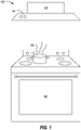
- FIG. 1 illustrates an example cooking environment 100 having a cooking appliance 102 and a vent hood 106.
- the cooking environment 100 may include a kitchen or other room in which cooking activities may be performed.
- cooking involves the use of heat to prepare food for consumption.
- Some example cooking techniques include grilling, baking, frying, frying, or microwaving.
- the cooking appliance 102 such as a stove, oven, microwave, etc., may be used to perform the cooking techniques.
- a side effect of cooking may involve the introduction of particulate 104 into the air of the cooking environment.
- Vent hoods 106 are generally designed to remove odors, moisture and grease from the cooking environment 100, as well as carbon monoxide, nitrogen dioxide, and other pollutants. Some vent hoods 106 are ducted or vented to evacuate air from the cooking environment 100 to the outside. Other vent hoods 106 are ductless, and filter and recirculate cleaned air back into the cooking environment 100. As shown, many hoods are placed in the cooking environment 100 above the cooking appliance 102. However, some vent hoods 106 are downdraft hoods that are placed below the cooking appliance 102.
- the vent hood 106 may generally include user interface controls 108 to allow a user to activate or deactivate the vent hood 106. For instance, the user may turn on the vent hood 106 while cooking and may turn the vent hood 106 off once the cooking operation is complete. As another possibility, the user may elect to turn on the vent hood 106 to vent out the cooking environment 100 for a reason unrelated to cooking, such as the existence of an undesirable smell in the cooking environment 100.
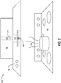
- FIG. 2 illustrates an example environment 200 including further details of the vent hood 106.
- the vent hood 106 may include an exhaust fan or blower 202, which is coupled to an exhaust duct 204, which may discharge impure air to the outside atmosphere, such as via a roof jack or wall cap through a wall of the building.
- the vent hood 106 further includes a filter 206 at the intake of the blower 202, which may be used to filter the impure air before passing the air into the exhaust duct 204. If the vent hood 106 includes a filter 206, the exhaust duct 204 of the vent hood 106 may instead vent back into the cooking environment 100, as the air has been cleaned of the particulate 104 by its passage through the material of the filter 206.
- a pre-filter air quality sensor 208 may be placed in the vent hood 106 to provide a signal indicative of the air quality parameters of the air in the proximity of the vent hood 106.
- Indoor air quality (IAQ) parameters sensed by the pre-filter air quality sensor 208 may include one or more atmospheric particulate matter smaller than 2.5 microns (PM2.5), VOCs such as aldehydes and polycyclic aromatic hydrocarbons (PAH), CO 2 , and CO. This signal may be used as an input to a decision regarding whether to turn on the blower 202 and pass the air through the filter 206.
- IAQ Indoor air quality
- a post-filter air quality sensor 210 may be placed within the exhaust duct 204 or at an exit from the exhaust duct 204. This post-filter air quality sensor 210 may provide a second signal indicative of the air quality parameters of the air after passage through the filter 206. If the air quality indicated by the post-filter air quality sensor 210 is not improved as compared to the air quality indicated by the pre-filter air quality sensor 208, then the filter 206 may no longer be removing particulate 104 from the air. If so, it may be advisable to clean or replace the filter 206. This approach may remove guesswork out of deciding when to replace the filter 206 based on performance of the filter 206.
- FIG. 3 illustrates an example system 300 for the application of a venting control strategy 304 to the operation of the vent hood 106.
- a vent hood controller 302 may include a storage 306 configured to maintain the venting control strategy 304, as well as one or more processors 308 to perform instructions, commands, and other routines in support of the operations of the vent hood controller 302 described herein.
- the vent hood controller 302 may be configured to execute instructions to automatically turn on and off the blower 202.
- the vent hood controller 302 may also be configured to execute instructions to indicate alerts with respect to replacement of the filter 206.
- Such instructions and other data may be maintained in a non-volatile manner using a variety of types of computer-readable storage 306.
- the computer-readable medium also referred to as a processor-readable medium or storage
- Computer-executable instructions may be compiled or interpreted from computer programs created using a variety of programming languages and/or technologies, including, without limitation, and either alone or in combination, JAVA, C, C++, C#, OBJECTIVE C, FORTRAN, PASCAL, JAVASCRIPT, PYTHON, PERL, etc.
- the vent hood controller 302 may be configured to receive input from the user interface controls 108 to provide for manual control of the blower 202.
- the user interface controls 108 may include controls to turn the blower 202 on or off.
- the user interface controls 108 may provide for multiple levels of blower operation, such as off, low, medium, and high airflow.
- the user interface controls 108 may further include an indication of the current level of operation of the blower 202. For instance, the currently selected level of blower operation in the user interface controls 108 may be backlit.
- the vent hood controller 302 may be further configured to receive input from the pre-filter air quality sensor 208 and the post-filter air quality sensor 210. Based on the venting control strategy 304, the vent hood controller 302 may utilize signals from the pre-filter air quality sensor 208 to determine whether to automatically control the blower 202 on or off. For instance, if the level of particulate as indicated by the signal from the pre-filter air quality sensor 208 exceeds a predefined threshold, then the vent hood controller 302 may automatically activate the blower 202 as specified by the venting control strategy 304, despite a lack of user input to the user interface controls 108.
- the vent hood controller 302 may also utilize the signals from the pre-filter air quality sensor 208 to automatically deactivate the blower 202 as specified by the venting control strategy 304, despite a lack of user input to the user interface controls 108. For instance, if the blower 202 is on, but particulate levels as indicated by the pre-filter air quality sensor 208 are below the predefined threshold (or second predefined threshold lower than the first predefined threshold may be specified by the venting control strategy 304 to provide hysteresis), then the vent hood controller 302 may automatically deactivate the blower 202.
- the vent hood controller 302 may utilize multiple thresholds and corresponding speeds. For instance, if the level of particulate as indicated by the signal from the pre-filter air quality sensor 208 exceeds a first predefined threshold specified by the venting control strategy 304, then the vent hood controller 302 may automatically activate the blower 202 at a first speed specified by the venting control strategy 304, while if the level of particulate as indicated by the signal from the pre-filter air quality sensor 208 exceeds a second, higher predefined threshold specified by the venting control strategy 304, then the vent hood controller 302 may automatically activate the blower 202 at a second, higher speed specified by the venting control strategy 304. Similarly, slowdown or deactivation of the blower 202 may be performed by the vent hood controller 302.
- the vent hood controller 302 may additionally or alternately utilize the signal from the post-filter air quality sensor 210 to determine whether to turn the blower 202 on, off, up, or down. Regardless of whether one or both of the pre-filter air quality sensor 208 or post-filter air quality sensor 210 are used, this approach to automatic activation of the vent hood 106 may prevent particulate from increasing to undesirable levels within the cooking environment 100. As another example, this approach may avoid a smoke alarm from accidentally being triggered due to cooking, by turning on the blower 202 prior to smoke filling the cooking environment 100.
- the vent hood controller 302 may be further configured to utilize a difference in the signals between the pre-filter air quality sensor 208 and the post-filter air quality sensor 210 to identify the effectiveness of the filter 206. For instance, if the air quality as indicated by the post-filter air quality sensor 210 is less than a predefined percentage cleaner than the air quality as indicated by the pre-filter air quality sensor 208, then the vent hood controller 302 may indicate that the filter 206 requires cleaning or replacement.
- the user interface controls 108 may include an indicator that can be illuminated or otherwise activated by the vent hood controller 302 to indicate that the filter 206 is not operating effectively.
- the vent hood controller 302 may be further configured to communicate with other components external to the vent hood 106.
- the vent hood controller 302 may include a wireless transceiver 310 (e.g., a BLUETOOTH module, a ZIGBEE transceiver, a Wi-Fi transceiver, an IrDA transceiver, a radio frequency identification (RFID) transceiver, a cellular transceiver, etc.) configured to communicate over a network 312 (or directly to other devices depending on protocol) with compatible wireless devices.
- the compatible wireless devices may include, for example IOT sensors 314 and/or offboard devices 316.
- the IOT sensors 314 may include various devices configured to provide additional information to the vent hood controller 302.
- the IOT sensors 314 may include air quality sensors, which may be similar in operation to the pre-filter air quality sensor 208 and the post-filter air quality sensor 210 but may provide signal information wirelessly to the vent hood controller 302. This additional information may be used by the vent hood controller 302 to perform operations according to the air quality within the cooking environment 100.
- one or more IOT sensors 314 may be placed around the cooking environment 100, to allow the vent hood controller 302 to automatically activate the blower 202 based on pollutants detected at locations remote from the vent hood 106.
- the offboard devices 316 may be any of various types of portable computing devices, such as cellular phones, tablet computers, smart watches, laptop computers, portable music players, or other devices capable of communication with the vent hood controller 302.
- the offboard device 316 may be used to wirelessly control the operation of the vent hood 106.
- the offboard device 316 may execute program instructions using a processor of the offboard device 316 to receive input from a user and to wirelessly send commands to the transceiver 310 to cause the vent hood controller 302 to turn the blower on, off, up, or down.
- the offboard device 316 may display a user interface of blower controls, which may be selected by the user to invoke the various blower functions.
- the offboard device 316 may be configured to receive alerts from the vent hood controller 302. For instance, as discussed above, the vent hood controller 302 may determine that the filter 206 requires cleaning or replacement. If so, the vent hood controller 302 may utilize the transceiver 310 to send a wireless signal to cause the offboard device 316 to display an alert indicating that the filter 206 should be serviced.
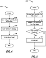
- FIG. 4 illustrates an example process 400 for the automatic control of the blower 202 of the vent hood 106.
- the process 400 may be performed by the vent hood controller 302 in the context of the system 300.
- the vent hood controller 302 receives signal input indicative of air quality.
- the vent hood controller 302 may receive the signal input from one or more sensors of the vent hood 106, such as the pre-filter air quality sensor 208 and/or the post-filter air quality sensor 210.
- the vent hood controller 302 may receive the signal input from one or more sensors external to the vent hood 106, such as one or more IOT sensors 314.
- the sensor input may provide information to the vent hood controller 302 with respect to air quality parameters, such as one or more of: atmospheric particulate matter smaller than 2.5 microns (PM2.5), VOC such as aldehydes and PAHs, CO 2 , and CO.
- air quality parameters such as one or more of: atmospheric particulate matter smaller than 2.5 microns (PM2.5), VOC such as aldehydes and PAHs, CO 2 , and CO.
- the vent hood controller 302 applies the venting control strategy 304 to the operation of the blower 202. For instance, if the level of particulate as indicated by the signal input exceeds a predefined threshold and the blower 202 is off, then the vent hood controller 302 may determine to activate the blower 202. If the blower 202 is on, but particulate levels as indicated by the signal input are below the predefined threshold (or second predefined threshold lower than the first predefined threshold to provide hysteresis), then the vent hood controller 302 may determine to automatically deactivate the blower 202.
- the vent hood controller 302 may determine to activate the blower 202 at a first speed, while if the level of particulate as indicated by the signal input exceeds a second, higher predefined threshold, then the vent hood controller 302 may determine to activate the blower 202 at a second, higher speed. Similarly, slowdown or deactivation of the blower 202 may be performed.
- the vent hood controller 302 updates the blower 202 speed in accordance with the venting control strategy 304. After operation 406, the process 400 ends. It should be noted that while the process 400 is shown as being linear, the process 400 may be executed continually, and one or more operations of the process 400 may be performed consecutively or concurrently.
- FIG. 5 illustrates an example process 500 for the automatic alerting that the filter 206 of the vent hood 106 requires service.
- the process 500 may be performed by the vent hood controller 302 in the context of the system 300.
- the vent hood controller 302 receives signal input from the pre-filter air quality sensor 208.
- the pre-filter air quality sensor 208 may be located at an inlet to the filter 206 and may accordingly provide signal input indicative of the air quality before the air has entered the filter 206.
- the sensor may be an IOT sensor 314 located within the cooking environment 100 remote from the vent hood 106. Regardless of location, the sensor input may provide information to the vent hood controller 302 with respect to air quality parameters, such as one or more of: atmospheric particulate matter smaller than 2.5 microns (PM2.5), VOCs such as aldehydes and PAH, CO 2 , and CO.
- air quality parameters such as one or more of: atmospheric particulate matter smaller than 2.5 microns (PM2.5), VOCs such as aldehydes and PAH, CO 2 , and CO.
- the vent hood controller 302 receives signal input from the post-filter air quality sensor 210.
- the post-filter air quality sensor 210 may be located at an outlet from the filter 206 and may accordingly provide signal input indicative of the air quality after the air has passed through the filter 206.
- sensor input may provide information to the vent hood controller 302 with respect to the same or similar air quality parameters.
- the vent hood controller 302 determines whether the filter 206 is operating effectively. If the air quality indicated by the post-filter air quality sensor 210 is not improved as compared to the air quality indicated by the pre-filter air quality sensor 208, then the filter 206 may no longer be removing particulate 104 from the air. If so, it may be advisable to clean or replace the filter 206. In an example, the vent hood controller 302 may compare the air quality before the filter 206 as indicated by the pre-filter air quality sensor 208 with the air quality after the filter 206 as indicated by the post-filter air quality sensor 210. If the difference in air quality is at least a minimum difference in absolute, relative, and/or percentage of one or more of the air quality parameters, then the process 500 may end. If, however, the difference is not at least a minimum difference control passes to operation 508. The specific air quality metrics to measure, and the specific minimum differences to utilize may be specified by the venting control strategy 304.
- the vent hood controller 302 indicates an alert.
- the vent hood controller 302 may activate an indicator on the user interface controls 108 to indicate that the filter 206 is not operating effectively.
- the vent hood controller 302 may utilize the transceiver 310 to send a wireless alert to the offboard device 316. This alert may be displayed by the offboard device 316, alerting the user of the offboard device 316 of the condition of the filter 206
- process 500 ends. It should be noted that while the process 500 is shown as being linear, the process 500 may be executed continually, and one or more operations of the process 500 may be performed consecutively or concurrently.
- filter performance may be inferred based on a baseline level instead of using the signal from the pre-filter air quality sensor 208.
- the vent hood controller 302 may establish a baseline level of air quality parameters over time. This baseline may be set by measurement of air quality parameters responsive to replacement of the filter 206, as an average level of air quality parameters over time, etc. If the signal from the post-filter air quality sensor 210 indicates that measured levels of air quality parameters worsen as compared to the baseline, then the vent hood controller 302 may infer that the filter 206 is no longer operating effectively and may raise the alert at operation 506.
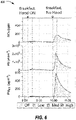
- FIG. 6 illustrates an example set of graphs 600 of the air quality parameters in view of the application of the venting control strategy 304 to the operation of the vent hood 106.
- the Y-axis of the graph illustrates various measures of particulates in the cooking environment 100. While NOx (ppb), PN (#cm -3 ), and PM2.5 ( ⁇ gm -3 ) are illustrated, other measures of particulates may be used. These particulates may be sensed, for example, by the pre-filter air quality sensor 208 and/or the IOT sensors 314.
- the X-axis of the set of graphs 600 is time of day.
- the venting control strategy 304 invokes the blower 202 responsive to the detection of particulates. This is compared to the scenario shown on the right of the set of graphs 600, where the blower 202 is not activated.
- the vent hood 106 automatically reduces the amount of particulates in the cooking environment 100, improving the IAQ within the cooking environment 100 and throughout the home.
- the processes, methods, or algorithms disclosed herein can be deliverable to/implemented by a processing device, controller, or computer, which can include any existing programmable electronic control unit or dedicated electronic control unit.
- the processes, methods, or algorithms can be stored as data and instructions executable by a controller or computer in many forms including, but not limited to, information permanently stored on non-writable storage media such as read-only memory (ROM) devices and information alterably stored on writable storage media such as floppy disks, magnetic tapes, compact discs (CDs), random access memory (RAM) devices, and other magnetic and optical media.
- ROM read-only memory
- CDs compact discs
- RAM random access memory
- the processes, methods, or algorithms can also be implemented in a software executable object.
- the processes, methods, or algorithms can be embodied in whole or in part using suitable hardware components, such as Application Specific Integrated Circuits (ASICs), Field-Programmable Gate Arrays (FPGAs), state machines, controllers or other hardware components or devices, or a combination of hardware, software and firmware components.
- suitable hardware components such as Application Specific Integrated Circuits (ASICs), Field-Programmable Gate Arrays (FPGAs), state machines, controllers or other hardware components or devices, or a combination of hardware, software and firmware components.
Landscapes
- Chemical & Material Sciences (AREA)
- Engineering & Computer Science (AREA)
- Chemical Kinetics & Catalysis (AREA)
- Combustion & Propulsion (AREA)
- Mechanical Engineering (AREA)
- General Engineering & Computer Science (AREA)
- Computer Networks & Wireless Communication (AREA)
- Ventilation (AREA)
Abstract
Description
- Aspects of the disclosure generally relate to a vent hood for sensing air quality, and for automatically performing operations based on the air quality.
- Vent hoods are generally designed to remove odors, moisture, grease from the cooking environment, as well as carbon monoxide, nitrogen dioxide, and other pollutants. Some hoods are ducted or vented to evacuate air from the cooking environment to the outside. Other hoods are ductless, and recirculate filtered air back into the cooking environment.
- In an illustrative embodiment, a vent hood is configured to receive air from a cooking environment, the vent hood including a filter. A post-filter air quality sensor is configured to provide an air quality signal indicative of sensed air quality parameters of air after exiting the filter. A vent hood controller is configured to indicate an alert that the filter requires servicing, based on a comparison of the sensed air quality parameters to baseline air quality parameters indicating a lack of filter efficiency.
- In one or more illustrative embodiments, a pre-filter air quality sensor may be configured to provide the baseline air quality parameters as a pre-filter signal indicative of the baseline air quality parameters of the air before entering the filter. In one or more illustrative embodiments, the pre-filter air quality sensor may be located at an inlet to the filter, and the post-filter air quality sensor is located at an outlet from the filter. In one or more illustrative embodiments, the pre-filter air quality sensor may be an internet of things (IOT) sensor located within the cooking environment remote from the vent hood.
- In one or more illustrative embodiments, the vent hood controller may be further configured to activate a blower of the vent hood responsive to the pre-filter air quality sensor indicating that the baseline air quality parameters exceed a predefined threshold.
- In one or more illustrative embodiments, the vent hood controller may be further configured to deactivate the blower of the vent hood responsive to the pre-filter air quality sensor indicating that the baseline air quality parameters no longer exceed the predefined threshold. In one or more illustrative embodiments, the vent hood controller may be further configured to infer the baseline air quality parameters as a historical average of the sensed air quality parameters measured by the post-filter air quality sensor.
- In one or more illustrative embodiments, the vent hood controller may be connected to a network and further configured to provide the alert to an offboard device via the network. In one or more illustrative embodiments, the vent hood controller may be further configured to display the alert using user interface controls of the vent hood.
- In one or more illustrative embodiments, the baseline air quality parameters and the sensed air quality parameters may include one or more of atmospheric particulate matter smaller than 2.5 microns (PM2.5), volatile organic compounds (VOC), carbon dioxide (CO2), or carbon monoxide (CO). In one or more illustrative embodiments, the comparison of the sensed air quality parameters to the baseline air quality parameters may include to determine a difference between the baseline air quality parameters and the sensed air quality parameters as an absolute, relative, and/or percentage, and indicate the alert responsive to the difference exceeding at least a predefined threshold difference.
- In one or more illustrative embodiments, the vent hood controller may be further configured to activate a blower of the vent hood responsive to the sensed air quality parameters exceeding a predefined threshold. The vent hood controller may be further configured to deactivate the blower of the vent hood responsive to the sensed air quality parameters of the air before entering the filter no longer exceeding the predefined threshold.
- In one or more illustrative embodiments, the vent hood controller may be further configured to activate a blower of the vent hood at a first speed setting responsive to the baseline air quality parameters exceeding a first predefined threshold; activate the blower at a second speed setting responsive to the baseline air quality parameters exceeding a second predefined threshold, the second speed setting being faster than the first speed setting, the second predefined threshold being higher than the first predefined threshold; and deactivate the blower of the vent hood responsive to the baseline air quality parameters of the air no longer exceeding the first predefined threshold.
- In a second illustrative example, a vent hood method is provided. A first air quality signal indicative of air quality parameters of air before entering a filter of a vent hood is received from a pre-filter air quality sensor. A second air quality signal indicative of the air quality parameters of the air after exiting the filter is received from a post-filter air quality sensor. An alert that the filter requires servicing is indicated based on a comparison of the first and second air quality signals indicating a lack of filter efficiency.
- In one or more illustrative embodiments, the first air quality signal may be received from a pre-filter air quality sensor. In one or more illustrative embodiments, the pre-filter air quality sensor may be located on an inlet to the filter. In one or more illustrative embodiments, the pre-filter air quality sensor may be an IOT sensor located within a cooking environment remote from the vent hood. In one or more illustrative embodiments, the post-filter air quality sensor may be located on an outlet from the filter. In one or more illustrative embodiments, the first air quality signal may be inferred as a baseline average of historical air quality parameters measured by the post-filter air quality sensor.
- In one or more illustrative embodiments, the alert may be provided to an offboard device via wireless communication. In one or more illustrative embodiments, the alert may be displayed using user interface controls of the vent hood. In one or more illustrative embodiments, the air quality parameters may include one or more of PM2.5, VOC, CO2, or CO.
- In one or more illustrative embodiments, a difference may be determined in the air quality parameters as an absolute, relative, and/or percentage difference between the air quality parameters of the air entering the filter and the air quality parameters of the air exiting the filter. In one or more illustrative embodiments, the alert may be indicated responsive to the air quality parameters exceeding at least a predefined threshold difference.
- In one or more illustrative embodiments, a blower of the vent hood may be activated responsive to the air quality parameters exceeding a predefined threshold. In one or more illustrative embodiments, the blower of the vent hood may be deactivated responsive to the air quality parameters no longer exceeding the predefined threshold.
- In one or more illustrative embodiments, a blower of the vent hood may be activated at a first speed setting responsive to the air quality parameters of the air before entering the filter exceeding a first predefined threshold. In one or more illustrative embodiments, the blower may be activated at a second speed setting responsive to the air quality parameters of the air before entering the filter exceeding a second predefined threshold, the second speed setting being faster than the first speed setting, the second predefined threshold being higher than the first predefined threshold. In one or more illustrative embodiments, the blower of the vent hood may be deactivated responsive to the air quality parameters of the air before entering the filter no longer exceeding the first predefined threshold.
- In a third illustrative example, a non-transitory computer-readable medium includes instructions that, when executed by a processor of a controller of a vent hood, cause the vent hood to perform operations including to receive, from a pre-filter air quality sensor, a first air quality signal indicative of air quality parameters of air before entering a filter of a vent hood; receive, from a post-filter air quality sensor, a second air quality signal indicative of the air quality parameters of the air after exiting the filter; determine a difference in the air quality parameters as an absolute, relative, and/or percentage difference between the air quality parameters of the air entering the filter and the air quality parameters of the air exiting the filter; and indicate an alert that the filter requires servicing based on the difference in the first and second air quality signals indicating a lack of filter efficiency, wherein the air quality parameters include one or more of PM2.5, VOC, CO2, or CO.
- In one or more illustrative embodiments, the medium may further include instructions that, when executed by the processor of the controller of the vent hood, cause the vent hood to perform operations including to activate a blower of the vent hood at a first speed setting responsive to the air quality parameters of the air before entering the filter exceeding a first predefined threshold; activate the blower at a second speed setting responsive to the air quality parameters of the air before entering the filter exceeding a second predefined threshold, the second speed setting being faster than the first speed setting, the second predefined threshold being higher than the first predefined threshold; and deactivate the blower of the vent hood responsive to the air quality parameters of the air before entering the filter no longer exceeding the first predefined threshold.
-
-
FIG. 1 illustrates an example cooking environment having a cooking appliance and a vent hood; -
FIG. 2 illustrates an example environment including further details of the vent hood; -
FIG. 3 illustrates an example system for the application of a venting control strategy to the operation of the vent hood; -
FIG. 4 illustrates an example process for the automatic control of the blower of the vent hood; -
FIG. 5 illustrates an example process for the automatic alerting that the filter of the vent hood requires service; and -
FIG. 6 illustrates an example set of graphs of the air quality parameters in view of the application of the venting control strategy to the operation of the vent hood. - As required, detailed embodiments of the present disclosure are disclosed herein; however, it is to be understood that the disclosed embodiments are merely exemplary of the disclosure that may be embodied in various and alternative forms. The figures are not necessarily to scale; some features may be exaggerated or minimized to show details of particular components. Therefore, specific structural and functional details disclosed herein are not to be interpreted as limiting, but merely as a representative basis for teaching one skilled in the art to variously employ the present disclosure.
- Aspects of the disclosure relate to the automatic activation of a vent hood to maintain indoor air quality. A system may include a sensor in a vent hood to detect indoor air quality coming in through the vent hood. The system may automatically turn on the vent hood based on air quality parameters. In addition, the system may include a sensor at an outlet of a vent hood filter and may trigger IOT notifications to replace the filter when needed. Further, the system may obtain data from off-board sensors, such as PM2.5, VOC, CO2, or CO, for measuring indoor air quality when deciding when to turn on the vent hood.
-
FIG. 1 illustrates anexample cooking environment 100 having acooking appliance 102 and avent hood 106. Thecooking environment 100 may include a kitchen or other room in which cooking activities may be performed. In general, cooking involves the use of heat to prepare food for consumption. Some example cooking techniques include grilling, baking, frying, frying, or microwaving. Thecooking appliance 102, such as a stove, oven, microwave, etc., may be used to perform the cooking techniques. In addition to the preparation of food, a side effect of cooking may involve the introduction ofparticulate 104 into the air of the cooking environment. -
Vent hoods 106 are generally designed to remove odors, moisture and grease from thecooking environment 100, as well as carbon monoxide, nitrogen dioxide, and other pollutants. Some venthoods 106 are ducted or vented to evacuate air from thecooking environment 100 to the outside.Other vent hoods 106 are ductless, and filter and recirculate cleaned air back into thecooking environment 100. As shown, many hoods are placed in thecooking environment 100 above thecooking appliance 102. However, somevent hoods 106 are downdraft hoods that are placed below thecooking appliance 102. - The
vent hood 106 may generally include user interface controls 108 to allow a user to activate or deactivate thevent hood 106. For instance, the user may turn on thevent hood 106 while cooking and may turn thevent hood 106 off once the cooking operation is complete. As another possibility, the user may elect to turn on thevent hood 106 to vent out thecooking environment 100 for a reason unrelated to cooking, such as the existence of an undesirable smell in thecooking environment 100. -
FIG. 2 illustrates anexample environment 200 including further details of thevent hood 106. As shown, thevent hood 106 may include an exhaust fan orblower 202, which is coupled to anexhaust duct 204, which may discharge impure air to the outside atmosphere, such as via a roof jack or wall cap through a wall of the building. In some examples, thevent hood 106 further includes afilter 206 at the intake of theblower 202, which may be used to filter the impure air before passing the air into theexhaust duct 204. If thevent hood 106 includes afilter 206, theexhaust duct 204 of thevent hood 106 may instead vent back into thecooking environment 100, as the air has been cleaned of the particulate 104 by its passage through the material of thefilter 206. - However, users may forget to turn on the
vent hood 106 while cooking. This may allow for the uncontrolled release of pollutants, such as VOCs and particulates, into thecooking environment 100. Accordingly, a pre-filterair quality sensor 208 may be placed in thevent hood 106 to provide a signal indicative of the air quality parameters of the air in the proximity of thevent hood 106. Indoor air quality (IAQ) parameters sensed by the pre-filterair quality sensor 208 may include one or more atmospheric particulate matter smaller than 2.5 microns (PM2.5), VOCs such as aldehydes and polycyclic aromatic hydrocarbons (PAH), CO2, and CO. This signal may be used as an input to a decision regarding whether to turn on theblower 202 and pass the air through thefilter 206. - Additionally, a post-filter
air quality sensor 210 may be placed within theexhaust duct 204 or at an exit from theexhaust duct 204. This post-filterair quality sensor 210 may provide a second signal indicative of the air quality parameters of the air after passage through thefilter 206. If the air quality indicated by the post-filterair quality sensor 210 is not improved as compared to the air quality indicated by the pre-filterair quality sensor 208, then thefilter 206 may no longer be removing particulate 104 from the air. If so, it may be advisable to clean or replace thefilter 206. This approach may remove guesswork out of deciding when to replace thefilter 206 based on performance of thefilter 206. -
FIG. 3 illustrates anexample system 300 for the application of aventing control strategy 304 to the operation of thevent hood 106. Avent hood controller 302 may include astorage 306 configured to maintain theventing control strategy 304, as well as one ormore processors 308 to perform instructions, commands, and other routines in support of the operations of thevent hood controller 302 described herein. - The
vent hood controller 302 may be configured to execute instructions to automatically turn on and off theblower 202. Thevent hood controller 302 may also be configured to execute instructions to indicate alerts with respect to replacement of thefilter 206. Such instructions and other data may be maintained in a non-volatile manner using a variety of types of computer-readable storage 306. The computer-readable medium (also referred to as a processor-readable medium or storage) includes any non-transitory medium (e.g., a tangible medium) that participates in providing instructions or other data that may be read by the one ormore processors 308 of thevent hood controller 302. Computer-executable instructions may be compiled or interpreted from computer programs created using a variety of programming languages and/or technologies, including, without limitation, and either alone or in combination, JAVA, C, C++, C#, OBJECTIVE C, FORTRAN, PASCAL, JAVASCRIPT, PYTHON, PERL, etc. - The
vent hood controller 302 may be configured to receive input from the user interface controls 108 to provide for manual control of theblower 202. For instance, the user interface controls 108 may include controls to turn theblower 202 on or off. In another example, the user interface controls 108 may provide for multiple levels of blower operation, such as off, low, medium, and high airflow. In some instances, the user interface controls 108 may further include an indication of the current level of operation of theblower 202. For instance, the currently selected level of blower operation in the user interface controls 108 may be backlit. - The
vent hood controller 302 may be further configured to receive input from the pre-filterair quality sensor 208 and the post-filterair quality sensor 210. Based on the ventingcontrol strategy 304, thevent hood controller 302 may utilize signals from the pre-filterair quality sensor 208 to determine whether to automatically control theblower 202 on or off. For instance, if the level of particulate as indicated by the signal from the pre-filterair quality sensor 208 exceeds a predefined threshold, then thevent hood controller 302 may automatically activate theblower 202 as specified by the ventingcontrol strategy 304, despite a lack of user input to the user interface controls 108. Thevent hood controller 302 may also utilize the signals from the pre-filterair quality sensor 208 to automatically deactivate theblower 202 as specified by the ventingcontrol strategy 304, despite a lack of user input to the user interface controls 108. For instance, if theblower 202 is on, but particulate levels as indicated by the pre-filterair quality sensor 208 are below the predefined threshold (or second predefined threshold lower than the first predefined threshold may be specified by the ventingcontrol strategy 304 to provide hysteresis), then thevent hood controller 302 may automatically deactivate theblower 202. - In another example, the
vent hood controller 302 may utilize multiple thresholds and corresponding speeds. For instance, if the level of particulate as indicated by the signal from the pre-filterair quality sensor 208 exceeds a first predefined threshold specified by the ventingcontrol strategy 304, then thevent hood controller 302 may automatically activate theblower 202 at a first speed specified by the ventingcontrol strategy 304, while if the level of particulate as indicated by the signal from the pre-filterair quality sensor 208 exceeds a second, higher predefined threshold specified by the ventingcontrol strategy 304, then thevent hood controller 302 may automatically activate theblower 202 at a second, higher speed specified by the ventingcontrol strategy 304. Similarly, slowdown or deactivation of theblower 202 may be performed by thevent hood controller 302. - Variations on the automatic operation are possible. For instance, similar to the use of the signal from the pre-filter
air quality sensor 208, thevent hood controller 302 may additionally or alternately utilize the signal from the post-filterair quality sensor 210 to determine whether to turn theblower 202 on, off, up, or down. Regardless of whether one or both of the pre-filterair quality sensor 208 or post-filterair quality sensor 210 are used, this approach to automatic activation of thevent hood 106 may prevent particulate from increasing to undesirable levels within thecooking environment 100. As another example, this approach may avoid a smoke alarm from accidentally being triggered due to cooking, by turning on theblower 202 prior to smoke filling thecooking environment 100. - Moreover, the
vent hood controller 302 may be further configured to utilize a difference in the signals between the pre-filterair quality sensor 208 and the post-filterair quality sensor 210 to identify the effectiveness of thefilter 206. For instance, if the air quality as indicated by the post-filterair quality sensor 210 is less than a predefined percentage cleaner than the air quality as indicated by the pre-filterair quality sensor 208, then thevent hood controller 302 may indicate that thefilter 206 requires cleaning or replacement. In an example, the user interface controls 108 may include an indicator that can be illuminated or otherwise activated by thevent hood controller 302 to indicate that thefilter 206 is not operating effectively. - The
vent hood controller 302 may be further configured to communicate with other components external to thevent hood 106. For instance, thevent hood controller 302 may include a wireless transceiver 310 (e.g., a BLUETOOTH module, a ZIGBEE transceiver, a Wi-Fi transceiver, an IrDA transceiver, a radio frequency identification (RFID) transceiver, a cellular transceiver, etc.) configured to communicate over a network 312 (or directly to other devices depending on protocol) with compatible wireless devices. The compatible wireless devices may include, forexample IOT sensors 314 and/oroffboard devices 316. - The
IOT sensors 314 may include various devices configured to provide additional information to thevent hood controller 302. In an example, theIOT sensors 314 may include air quality sensors, which may be similar in operation to the pre-filterair quality sensor 208 and the post-filterair quality sensor 210 but may provide signal information wirelessly to thevent hood controller 302. This additional information may be used by thevent hood controller 302 to perform operations according to the air quality within thecooking environment 100. For instance, one ormore IOT sensors 314 may be placed around thecooking environment 100, to allow thevent hood controller 302 to automatically activate theblower 202 based on pollutants detected at locations remote from thevent hood 106. - The
offboard devices 316 may be any of various types of portable computing devices, such as cellular phones, tablet computers, smart watches, laptop computers, portable music players, or other devices capable of communication with thevent hood controller 302. In an example, theoffboard device 316 may be used to wirelessly control the operation of thevent hood 106. For instance, theoffboard device 316 may execute program instructions using a processor of theoffboard device 316 to receive input from a user and to wirelessly send commands to thetransceiver 310 to cause thevent hood controller 302 to turn the blower on, off, up, or down. In one example, theoffboard device 316 may display a user interface of blower controls, which may be selected by the user to invoke the various blower functions. - In another example, the
offboard device 316 may be configured to receive alerts from thevent hood controller 302. For instance, as discussed above, thevent hood controller 302 may determine that thefilter 206 requires cleaning or replacement. If so, thevent hood controller 302 may utilize thetransceiver 310 to send a wireless signal to cause theoffboard device 316 to display an alert indicating that thefilter 206 should be serviced. -
FIG. 4 illustrates anexample process 400 for the automatic control of theblower 202 of thevent hood 106. In an example, theprocess 400 may be performed by thevent hood controller 302 in the context of thesystem 300. - At
operation 402, thevent hood controller 302 receives signal input indicative of air quality. In an example, thevent hood controller 302 may receive the signal input from one or more sensors of thevent hood 106, such as the pre-filterair quality sensor 208 and/or the post-filterair quality sensor 210. In another example, thevent hood controller 302 may receive the signal input from one or more sensors external to thevent hood 106, such as one ormore IOT sensors 314. The sensor input may provide information to thevent hood controller 302 with respect to air quality parameters, such as one or more of: atmospheric particulate matter smaller than 2.5 microns (PM2.5), VOC such as aldehydes and PAHs, CO2, and CO. - At
operation 404, thevent hood controller 302 applies the ventingcontrol strategy 304 to the operation of theblower 202. For instance, if the level of particulate as indicated by the signal input exceeds a predefined threshold and theblower 202 is off, then thevent hood controller 302 may determine to activate theblower 202. If theblower 202 is on, but particulate levels as indicated by the signal input are below the predefined threshold (or second predefined threshold lower than the first predefined threshold to provide hysteresis), then thevent hood controller 302 may determine to automatically deactivate theblower 202. In another example, if the level of particulate as indicated by the signal input exceeds a first predefined threshold, then thevent hood controller 302 may determine to activate theblower 202 at a first speed, while if the level of particulate as indicated by the signal input exceeds a second, higher predefined threshold, then thevent hood controller 302 may determine to activate theblower 202 at a second, higher speed. Similarly, slowdown or deactivation of theblower 202 may be performed. - At
operation 406, thevent hood controller 302 updates theblower 202 speed in accordance with the ventingcontrol strategy 304. Afteroperation 406, theprocess 400 ends. It should be noted that while theprocess 400 is shown as being linear, theprocess 400 may be executed continually, and one or more operations of theprocess 400 may be performed consecutively or concurrently. -
FIG. 5 illustrates anexample process 500 for the automatic alerting that thefilter 206 of thevent hood 106 requires service. As with theprocess 400, theprocess 500 may be performed by thevent hood controller 302 in the context of thesystem 300. - At
operation 502, thevent hood controller 302 receives signal input from the pre-filterair quality sensor 208. The pre-filterair quality sensor 208 may be located at an inlet to thefilter 206 and may accordingly provide signal input indicative of the air quality before the air has entered thefilter 206. In another example, the sensor may be anIOT sensor 314 located within thecooking environment 100 remote from thevent hood 106. Regardless of location, the sensor input may provide information to thevent hood controller 302 with respect to air quality parameters, such as one or more of: atmospheric particulate matter smaller than 2.5 microns (PM2.5), VOCs such as aldehydes and PAH, CO2, and CO. - At
operation 504, thevent hood controller 302 receives signal input from the post-filterair quality sensor 210. The post-filterair quality sensor 210 may be located at an outlet from thefilter 206 and may accordingly provide signal input indicative of the air quality after the air has passed through thefilter 206. As withoperation 502, sensor input may provide information to thevent hood controller 302 with respect to the same or similar air quality parameters. - At
operation 506, thevent hood controller 302 determines whether thefilter 206 is operating effectively. If the air quality indicated by the post-filterair quality sensor 210 is not improved as compared to the air quality indicated by the pre-filterair quality sensor 208, then thefilter 206 may no longer be removing particulate 104 from the air. If so, it may be advisable to clean or replace thefilter 206. In an example, thevent hood controller 302 may compare the air quality before thefilter 206 as indicated by the pre-filterair quality sensor 208 with the air quality after thefilter 206 as indicated by the post-filterair quality sensor 210. If the difference in air quality is at least a minimum difference in absolute, relative, and/or percentage of one or more of the air quality parameters, then theprocess 500 may end. If, however, the difference is not at least a minimum difference control passes tooperation 508. The specific air quality metrics to measure, and the specific minimum differences to utilize may be specified by the ventingcontrol strategy 304. - At
operation 508, thevent hood controller 302 indicates an alert. In an example, thevent hood controller 302 may activate an indicator on the user interface controls 108 to indicate that thefilter 206 is not operating effectively. In another example, thevent hood controller 302 may utilize thetransceiver 310 to send a wireless alert to theoffboard device 316. This alert may be displayed by theoffboard device 316, alerting the user of theoffboard device 316 of the condition of thefilter 206 - After
operation 508, theprocess 500 ends. It should be noted that while theprocess 500 is shown as being linear, theprocess 500 may be executed continually, and one or more operations of theprocess 500 may be performed consecutively or concurrently. - Variations on the
process 500 are possible. For instance, filter performance may be inferred based on a baseline level instead of using the signal from the pre-filterair quality sensor 208. In an example, thevent hood controller 302 may establish a baseline level of air quality parameters over time. This baseline may be set by measurement of air quality parameters responsive to replacement of thefilter 206, as an average level of air quality parameters over time, etc. If the signal from the post-filterair quality sensor 210 indicates that measured levels of air quality parameters worsen as compared to the baseline, then thevent hood controller 302 may infer that thefilter 206 is no longer operating effectively and may raise the alert atoperation 506. -
FIG. 6 illustrates an example set ofgraphs 600 of the air quality parameters in view of the application of the ventingcontrol strategy 304 to the operation of thevent hood 106. As shown, the Y-axis of the graph illustrates various measures of particulates in thecooking environment 100. While NOx (ppb), PN (#cm-3), and PM2.5 (µgm-3) are illustrated, other measures of particulates may be used. These particulates may be sensed, for example, by the pre-filterair quality sensor 208 and/or theIOT sensors 314. The X-axis of the set ofgraphs 600 is time of day. As can be seen to the left of the set ofgraphs 600, the ventingcontrol strategy 304 invokes theblower 202 responsive to the detection of particulates. This is compared to the scenario shown on the right of the set ofgraphs 600, where theblower 202 is not activated. Thus, by the automatic application of the venting control strategy 304 (such as shown in theprocesses 400 and 500), thevent hood 106 automatically reduces the amount of particulates in thecooking environment 100, improving the IAQ within thecooking environment 100 and throughout the home. - The processes, methods, or algorithms disclosed herein can be deliverable to/implemented by a processing device, controller, or computer, which can include any existing programmable electronic control unit or dedicated electronic control unit. Similarly, the processes, methods, or algorithms can be stored as data and instructions executable by a controller or computer in many forms including, but not limited to, information permanently stored on non-writable storage media such as read-only memory (ROM) devices and information alterably stored on writable storage media such as floppy disks, magnetic tapes, compact discs (CDs), random access memory (RAM) devices, and other magnetic and optical media. The processes, methods, or algorithms can also be implemented in a software executable object. Alternatively, the processes, methods, or algorithms can be embodied in whole or in part using suitable hardware components, such as Application Specific Integrated Circuits (ASICs), Field-Programmable Gate Arrays (FPGAs), state machines, controllers or other hardware components or devices, or a combination of hardware, software and firmware components.
- While exemplary embodiments are described above, it is not intended that these embodiments describe all possible forms encompassed by the claims. The words used in the specification are words of description rather than limitation, and it is understood that various changes can be made without departing from the spirit and scope of the disclosure. As previously described, the features of various embodiments can be combined to form further embodiments of the disclosure that may not be explicitly described or illustrated. While various embodiments could have been described as providing advantages or being preferred over other embodiments or prior art implementations with respect to one or more desired characteristics, those of ordinary skill in the art recognize that one or more features or characteristics can be compromised to achieve desired overall system attributes, which depend on the specific application and implementation. These attributes can include, but are not limited to cost, strength, durability, life cycle cost, marketability, appearance, packaging, size, serviceability, weight, manufacturability, ease of assembly, etc. As such, to the extent any embodiments are described as less desirable than other embodiments or prior art implementations with respect to one or more characteristics, these embodiments are not outside the scope of the disclosure and can be desirable for particular applications.
- With regard to the processes, systems, methods, heuristics, etc. described herein, it should be understood that, although the steps of such processes, etc. have been described as occurring according to a certain ordered sequence, such processes could be practiced with the described steps performed in an order other than the order described herein. It further should be understood that certain steps could be performed simultaneously, that other steps could be added, or that certain steps described herein could be omitted. In other words, the descriptions of processes herein are provided for the purpose of illustrating certain embodiments, and should in no way be construed so as to limit the claims.
- Accordingly, it is to be understood that the above description is intended to be illustrative and not restrictive. Many embodiments and applications other than the examples provided would be apparent upon reading the above description. The scope should be determined, not with reference to the above description, but should instead be determined with reference to the appended claims, along with the full scope of equivalents to which such claims are entitled. It is anticipated and intended that future developments will occur in the technologies discussed herein, and that the disclosed systems and methods will be incorporated into such future embodiments. In sum, it should be understood that the application is capable of modification and variation.
- All terms used in the claims are intended to be given their broadest reasonable constructions and their ordinary meanings as understood by those knowledgeable in the technologies described herein unless an explicit indication to the contrary is made herein. In particular, use of the singular articles such as "a," "the," "said," etc. should be read to recite one or more of the indicated elements unless a claim recites an explicit limitation to the contrary.
- The abstract of the disclosure is provided to allow the reader to quickly ascertain the nature of the technical disclosure. It is submitted with the understanding that it will not be used to interpret or limit the scope or meaning of the claims. In addition, in the foregoing Detailed Description, it can be seen that various features are grouped together in various embodiments for the purpose of streamlining the disclosure. This method of disclosure is not to be interpreted as reflecting an intention that the claimed embodiments require more features than are expressly recited in each claim. Rather, as the following claims reflect, inventive subject matter lies in less than all features of a single disclosed embodiment. Thus, the following claims are hereby incorporated into the Detailed Description, with each claim standing on its own as a separately claimed subject matter.
- While exemplary embodiments are described above, it is not intended that these embodiments describe all possible forms of the disclosure. Rather, the words used in the specification are words of description rather than limitation, and it is understood that various changes may be made without departing from the spirit and scope of the disclosure. Additionally, the features of various implementing embodiments may be combined to form further embodiments of the disclosure.
Claims (15)
- A vent hood (106) sensing system (300) comprising:a vent hood (106) configured to receive air from a cooking environment (100), the vent hood (106) including a filter (206);a post-filter air quality sensor (210) configured to provide an air quality signal indicative of sensed air quality parameters of air after exiting the filter (206); anda vent hood controller (302) configured to indicate an alert that the filter (206) requires servicing, based on a comparison of the sensed air quality parameters to baseline air quality parameters indicating a lack of filter (206) efficiency.
- The system (300) of claim 1, further comprising a pre-filter air quality sensor (208) configured to provide the baseline air quality parameters as a pre-filter signal indicative of the baseline air quality parameters of the air before entering the filter (206).
- The system (300) of claim 2, wherein the pre-filter air quality sensor (208) is located at an inlet to the filter (206), and the post-filter air quality sensor (210) is located at an outlet from the filter (206).
- The system (300) of claim 2, wherein the pre-filter air quality sensor (208) is an internet of things (IOT) sensor located within the cooking environment (100) remote from the vent hood (106).
- The system (300) of claim 2, wherein the vent hood controller (302) is further configured to activate a blower (202) of the vent hood (106) responsive to the pre-filter air quality sensor (208) indicating that the baseline air quality parameters exceed a predefined threshold, and is optionally further configured to deactivate the blower (202) of the vent hood (106) responsive to the pre-filter air quality sensor (208) indicating that the baseline air quality parameters no longer exceed the predefined threshold.
- The system (300) of any one of claims 1-5, wherein the vent hood controller (302) is further configured to infer the baseline air quality parameters as a historical average of the sensed air quality parameters measured by the post-filter air quality sensor (210).
- The system (300) of any one of claims 1-6, wherein the vent hood controller (302) is connected to a network (312) and further configured to provide the alert to an offboard device via the network (312).
- The system (300) of any one of claims 1-7, wherein the vent hood controller (302) is further configured to display the alert using user interface controls (108) of the vent hood (106).
- The system (300) of any one of claims 1-8, wherein the baseline air quality parameters and the sensed air quality parameters include one or more of atmospheric particulate (104) matter smaller than 2.5 microns (PM2.5), volatile organic compounds (VOC), carbon dioxide (CO2), or carbon monoxide (CO).
- The system (300) of any one of claims 1-9, wherein the comparison of the sensed air quality parameters to the baseline air quality parameters includes to:determine a difference between the baseline air quality parameters and the sensed air quality parameters as an absolute, relative, and/or percentage; andindicate the alert responsive to the difference exceeding at least a predefined threshold difference.
- The system (300) of any one of claims 1-10, wherein the vent hood controller (302) is further configured to activate a blower (202) of the vent hood (106) responsive to the sensed air quality parameters exceeding a predefined threshold, and optionally further configured to deactivate the blower (202) of the vent hood (106) responsive to the sensed air quality parameters of the air before entering the filter (206) no longer exceeding the predefined threshold.
- The system (300) of any one of claims 1-11, wherein the vent hood controller (302) is further configured to:activate a blower (202) of the vent hood (106) at a first speed setting responsive to the baseline air quality parameters exceeding a first predefined threshold;activate the blower (202) at a second speed setting responsive to the baseline air quality parameters exceeding a second predefined threshold, the second speed setting being faster than the first speed setting, the second predefined threshold being higher than the first predefined threshold; anddeactivate the blower (202) of the vent hood (106) responsive to the baseline air quality parameters of the air no longer exceeding the first predefined threshold.
- A vent hood (106) sensing method (500), comprising:identifying a first air quality signal indicative of air quality parameters of air before entering a filter (206) of a vent hood (106);receiving, from a post-filter air quality sensor (210), a second air quality signal indicative of the air quality parameters of the air after exiting the filter (206); andindicating an alert that the filter (206) requires servicing based on a comparison of the first and second air quality signals indicating a lack of filter (206) efficiency.
- The method (500) of claim 13, further comprising:receiving the first air quality signal from a pre-filter air quality sensor (208), wherein one or more of the pre-filter air quality sensor (208) is located on an inlet to the filter (206), the pre-filter air quality sensor (208) is an internet of things (IOT) sensor located within a cooking environment (100) remote from the vent hood (106), or the post-filter air quality sensor (210) is located on an outlet from the filter (206); orinferring the first air quality signal as a baseline average of historical air quality parameters measured by the post-filter air quality sensor (210).
- The method (500) of any one of claims 13-14, further comprising:determining a difference in the air quality parameters as an absolute, relative, and/or percentage difference between the air quality parameters of the air entering the filter (206) and the air quality parameters of the air exiting the filter (206); andindicating the alert responsive to the air quality parameters exceeding at least a predefined threshold difference.
Applications Claiming Priority (1)
| Application Number | Priority Date | Filing Date | Title |
|---|---|---|---|
| US17/194,787 US20220282873A1 (en) | 2021-03-08 | 2021-03-08 | Automatic sensing vent hood |
Publications (2)
| Publication Number | Publication Date |
|---|---|
| EP4056906A1 true EP4056906A1 (en) | 2022-09-14 |
| EP4056906B1 EP4056906B1 (en) | 2024-05-15 |
Family
ID=80683709
Family Applications (1)
| Application Number | Title | Priority Date | Filing Date |
|---|---|---|---|
| EP22160626.2A Active EP4056906B1 (en) | 2021-03-08 | 2022-03-07 | Vent hood system with automatic sensing means |
Country Status (2)
| Country | Link |
|---|---|
| US (1) | US20220282873A1 (en) |
| EP (1) | EP4056906B1 (en) |
Families Citing this family (5)
| Publication number | Priority date | Publication date | Assignee | Title |
|---|---|---|---|---|
| TWI845888B (en) * | 2022-01-24 | 2024-06-21 | 研能科技股份有限公司 | Range hood for air pollution prevention |
| EP4224070A1 (en) * | 2022-02-04 | 2023-08-09 | Electrolux Appliances Aktiebolag | Cooker hood |
| US12474065B2 (en) * | 2022-02-16 | 2025-11-18 | Whirlpool Corporation | Ventilation system for a household appliance |
| EP4368899A1 (en) * | 2022-11-14 | 2024-05-15 | Electrolux Appliances Aktiebolag | Fume extraction system and method for operating an extraction device |
| TWI914603B (en) * | 2023-04-14 | 2026-02-11 | 研能科技股份有限公司 | Range hood |
Citations (6)
| Publication number | Priority date | Publication date | Assignee | Title |
|---|---|---|---|---|
| DE102005025787B3 (en) * | 2005-06-04 | 2007-01-04 | Diehl Ako Stiftung & Co. Kg | Fume removal hood as for cookers has fan, cleaning filter and air mass sensor and control to determine degree of filter contamination |
| WO2014019862A1 (en) * | 2012-08-02 | 2014-02-06 | BSH Bosch und Siemens Hausgeräte GmbH | Vapour extraction device and method for controlling a fan motor of a fan and for determining air cleaning effectiveness |
| US20140230662A1 (en) * | 2013-02-21 | 2014-08-21 | Rain Mountain, Llc | Intelligent ventilating safety range hood control system |
| EP2824395A2 (en) * | 2013-07-10 | 2015-01-14 | E.G.O. Elektro-Gerätebau GmbH | Method for operating an extractor hood and extractor hood |
| WO2020163443A1 (en) * | 2019-02-05 | 2020-08-13 | Oy Halton Group Ltd. | Cooking pollutant control methods devices and systems |
| CN111664490A (en) * | 2020-06-28 | 2020-09-15 | 海尔优家智能科技(北京)有限公司 | Control method and device of cigarette machine and storage medium |
Family Cites Families (12)
| Publication number | Priority date | Publication date | Assignee | Title |
|---|---|---|---|---|
| US20150082988A1 (en) * | 2008-04-08 | 2015-03-26 | Universal Technologies, Inc. | Air filter |
| US8372186B2 (en) * | 2009-08-14 | 2013-02-12 | Gregory J. Dobbyn | Ductless fume hood gas monitoring and detection system |
| WO2019050154A1 (en) * | 2017-09-05 | 2019-03-14 | 삼성전자주식회사 | Air purification device and method for controlling same |
| US10627378B2 (en) * | 2017-09-29 | 2020-04-21 | GreenAire Solutions, LLC | Volatile organic compound monitoring system |
| EP3488751B1 (en) * | 2017-11-22 | 2023-06-07 | Guido Valentini | Vacuum cleaner |
| CN110160094A (en) * | 2018-01-02 | 2019-08-23 | 湖南沃邦环保科技有限公司 | A kind of intelligent environment protection kitchen ventilator |
| TWM567364U (en) * | 2018-05-18 | 2018-09-21 | 研能科技股份有限公司 | Gas detection device |
| EP3712521B1 (en) * | 2019-03-19 | 2023-01-18 | LG Electronics Inc. | Air purifier and air purifying system |
| KR102783132B1 (en) * | 2019-08-19 | 2025-03-19 | 주식회사 경동나비엔 | Kitchen Hood and Ventilator and the control method thereof |
| KR102090584B1 (en) * | 2019-10-23 | 2020-03-18 | 한국건설기술연구원 | Apparatus and Method for Ventilating Kitchen |
| KR102216920B1 (en) * | 2019-10-28 | 2021-02-18 | 주식회사 에프티랩 | Radon management system using radon detector |
| CN112393295A (en) * | 2020-11-19 | 2021-02-23 | 佛山市大秉智能科技有限公司 | Oil smoke suction and exhaust mechanism with shared driving source |
-
2021
- 2021-03-08 US US17/194,787 patent/US20220282873A1/en not_active Abandoned
-
2022
- 2022-03-07 EP EP22160626.2A patent/EP4056906B1/en active Active
Patent Citations (6)
| Publication number | Priority date | Publication date | Assignee | Title |
|---|---|---|---|---|
| DE102005025787B3 (en) * | 2005-06-04 | 2007-01-04 | Diehl Ako Stiftung & Co. Kg | Fume removal hood as for cookers has fan, cleaning filter and air mass sensor and control to determine degree of filter contamination |
| WO2014019862A1 (en) * | 2012-08-02 | 2014-02-06 | BSH Bosch und Siemens Hausgeräte GmbH | Vapour extraction device and method for controlling a fan motor of a fan and for determining air cleaning effectiveness |
| US20140230662A1 (en) * | 2013-02-21 | 2014-08-21 | Rain Mountain, Llc | Intelligent ventilating safety range hood control system |
| EP2824395A2 (en) * | 2013-07-10 | 2015-01-14 | E.G.O. Elektro-Gerätebau GmbH | Method for operating an extractor hood and extractor hood |
| WO2020163443A1 (en) * | 2019-02-05 | 2020-08-13 | Oy Halton Group Ltd. | Cooking pollutant control methods devices and systems |
| CN111664490A (en) * | 2020-06-28 | 2020-09-15 | 海尔优家智能科技(北京)有限公司 | Control method and device of cigarette machine and storage medium |
Also Published As
| Publication number | Publication date |
|---|---|
| US20220282873A1 (en) | 2022-09-08 |
| EP4056906B1 (en) | 2024-05-15 |
Similar Documents
| Publication | Publication Date | Title |
|---|---|---|
| US20220282873A1 (en) | Automatic sensing vent hood | |
| US10767873B2 (en) | Air processing system and method | |
| KR102528805B1 (en) | Detect air filter condition | |
| KR102572499B1 (en) | System and method of controlling air quality, and analyzing server | |
| JP6491338B2 (en) | Systems and methods for monitoring air quality and events likely to affect air quality and taking corrective action | |
| CN109282444B (en) | Air conditioner, method and apparatus for controlling the same, and computer-readable storage medium | |
| JP2020004454A (en) | Alarm | |
| JP2019532263A (en) | Air filter condition sensing | |
| CN104807147A (en) | Controller, indoor environment regulating system and indoor environment regulation method | |
| KR20170048789A (en) | Device for removing dust of vehicle | |
| CN110645685B (en) | Security monitoring method and device based on fresh air machine | |
| CN105444377B (en) | A kind of air purifier control method and device | |
| KR102287675B1 (en) | System for simultaneous air cleaning at multi points | |
| US20180306455A1 (en) | Air treatment system | |
| JP7152149B2 (en) | Air conditioning system, program, information processing device and information processing method | |
| KR102380090B1 (en) | air conditioner and operating method thereof | |
| KR102380087B1 (en) | air conditioner and operating method thereof | |
| EP3023953B1 (en) | System and method of airflow monitoring for variable airflow environments | |
| KR101517332B1 (en) | System for providing Environment Information | |
| KR20160048241A (en) | Smart air care system and control method thereof | |
| CN117308298A (en) | Control methods, devices, equipment and storage media | |
| KR102331431B1 (en) | Air purifier, system for controling air purifier and method for controling air purifier | |
| CN117289629A (en) | A control method, system, equipment and medium for an intelligent air shower room | |
| FI20235498A1 (en) | Air quality monitoring | |
| KR20160069035A (en) | Air purifier, system for managing air purifier and method for controling air purifier |
Legal Events
| Date | Code | Title | Description |
|---|---|---|---|
| PUAI | Public reference made under article 153(3) epc to a published international application that has entered the european phase |
Free format text: ORIGINAL CODE: 0009012 |
|
| STAA | Information on the status of an ep patent application or granted ep patent |
Free format text: STATUS: THE APPLICATION HAS BEEN PUBLISHED |
|
| AK | Designated contracting states |
Kind code of ref document: A1 Designated state(s): AL AT BE BG CH CY CZ DE DK EE ES FI FR GB GR HR HU IE IS IT LI LT LU LV MC MK MT NL NO PL PT RO RS SE SI SK SM TR |
|
| RAP3 | Party data changed (applicant data changed or rights of an application transferred) |
Owner name: WHIRLPOOL CORPORATION |
|
| STAA | Information on the status of an ep patent application or granted ep patent |
Free format text: STATUS: REQUEST FOR EXAMINATION WAS MADE |
|
| 17P | Request for examination filed |
Effective date: 20230313 |
|
| RBV | Designated contracting states (corrected) |
Designated state(s): AL AT BE BG CH CY CZ DE DK EE ES FI FR GB GR HR HU IE IS IT LI LT LU LV MC MK MT NL NO PL PT RO RS SE SI SK SM TR |
|
| GRAP | Despatch of communication of intention to grant a patent |
Free format text: ORIGINAL CODE: EPIDOSNIGR1 |
|
| STAA | Information on the status of an ep patent application or granted ep patent |
Free format text: STATUS: GRANT OF PATENT IS INTENDED |
|
| INTG | Intention to grant announced |
Effective date: 20231213 |
|
| P01 | Opt-out of the competence of the unified patent court (upc) registered |
Effective date: 20231220 |
|
| GRAS | Grant fee paid |
Free format text: ORIGINAL CODE: EPIDOSNIGR3 |
|
| GRAA | (expected) grant |
Free format text: ORIGINAL CODE: 0009210 |
|
| STAA | Information on the status of an ep patent application or granted ep patent |
Free format text: STATUS: THE PATENT HAS BEEN GRANTED |
|
| AK | Designated contracting states |
Kind code of ref document: B1 Designated state(s): AL AT BE BG CH CY CZ DE DK EE ES FI FR GB GR HR HU IE IS IT LI LT LU LV MC MK MT NL NO PL PT RO RS SE SI SK SM TR |
|
| REG | Reference to a national code |
Ref country code: CH Ref legal event code: EP |
|
| REG | Reference to a national code |
Ref country code: IE Ref legal event code: FG4D |
|
| REG | Reference to a national code |
Ref country code: DE Ref legal event code: R096 Ref document number: 602022003416 Country of ref document: DE |
|
| REG | Reference to a national code |
Ref country code: LT Ref legal event code: MG9D |
|
| PG25 | Lapsed in a contracting state [announced via postgrant information from national office to epo] |
Ref country code: IS Free format text: LAPSE BECAUSE OF FAILURE TO SUBMIT A TRANSLATION OF THE DESCRIPTION OR TO PAY THE FEE WITHIN THE PRESCRIBED TIME-LIMIT Effective date: 20240915 |
|
| PG25 | Lapsed in a contracting state [announced via postgrant information from national office to epo] |
Ref country code: BG Free format text: LAPSE BECAUSE OF FAILURE TO SUBMIT A TRANSLATION OF THE DESCRIPTION OR TO PAY THE FEE WITHIN THE PRESCRIBED TIME-LIMIT Effective date: 20240515 |
|
| PG25 | Lapsed in a contracting state [announced via postgrant information from national office to epo] |
Ref country code: FI Free format text: LAPSE BECAUSE OF FAILURE TO SUBMIT A TRANSLATION OF THE DESCRIPTION OR TO PAY THE FEE WITHIN THE PRESCRIBED TIME-LIMIT Effective date: 20240515 Ref country code: HR Free format text: LAPSE BECAUSE OF FAILURE TO SUBMIT A TRANSLATION OF THE DESCRIPTION OR TO PAY THE FEE WITHIN THE PRESCRIBED TIME-LIMIT Effective date: 20240515 |
|
| PG25 | Lapsed in a contracting state [announced via postgrant information from national office to epo] |
Ref country code: GR Free format text: LAPSE BECAUSE OF FAILURE TO SUBMIT A TRANSLATION OF THE DESCRIPTION OR TO PAY THE FEE WITHIN THE PRESCRIBED TIME-LIMIT Effective date: 20240816 |
|
| PG25 | Lapsed in a contracting state [announced via postgrant information from national office to epo] |
Ref country code: PT Free format text: LAPSE BECAUSE OF FAILURE TO SUBMIT A TRANSLATION OF THE DESCRIPTION OR TO PAY THE FEE WITHIN THE PRESCRIBED TIME-LIMIT Effective date: 20240916 |
|
| REG | Reference to a national code |
Ref country code: AT Ref legal event code: MK05 Ref document number: 1687196 Country of ref document: AT Kind code of ref document: T Effective date: 20240515 |
|
| PG25 | Lapsed in a contracting state [announced via postgrant information from national office to epo] |
Ref country code: NL Free format text: LAPSE BECAUSE OF FAILURE TO SUBMIT A TRANSLATION OF THE DESCRIPTION OR TO PAY THE FEE WITHIN THE PRESCRIBED TIME-LIMIT Effective date: 20240515 |
|
| PG25 | Lapsed in a contracting state [announced via postgrant information from national office to epo] |
Ref country code: ES Free format text: LAPSE BECAUSE OF FAILURE TO SUBMIT A TRANSLATION OF THE DESCRIPTION OR TO PAY THE FEE WITHIN THE PRESCRIBED TIME-LIMIT Effective date: 20240515 |
|
| PG25 | Lapsed in a contracting state [announced via postgrant information from national office to epo] |
Ref country code: AT Free format text: LAPSE BECAUSE OF FAILURE TO SUBMIT A TRANSLATION OF THE DESCRIPTION OR TO PAY THE FEE WITHIN THE PRESCRIBED TIME-LIMIT Effective date: 20240515 |
|
| PG25 | Lapsed in a contracting state [announced via postgrant information from national office to epo] |
Ref country code: PL Free format text: LAPSE BECAUSE OF FAILURE TO SUBMIT A TRANSLATION OF THE DESCRIPTION OR TO PAY THE FEE WITHIN THE PRESCRIBED TIME-LIMIT Effective date: 20240515 |
|
| PG25 | Lapsed in a contracting state [announced via postgrant information from national office to epo] |
Ref country code: LV Free format text: LAPSE BECAUSE OF FAILURE TO SUBMIT A TRANSLATION OF THE DESCRIPTION OR TO PAY THE FEE WITHIN THE PRESCRIBED TIME-LIMIT Effective date: 20240515 |
|
| PG25 | Lapsed in a contracting state [announced via postgrant information from national office to epo] |
Ref country code: PT Free format text: LAPSE BECAUSE OF FAILURE TO SUBMIT A TRANSLATION OF THE DESCRIPTION OR TO PAY THE FEE WITHIN THE PRESCRIBED TIME-LIMIT Effective date: 20240916 Ref country code: PL Free format text: LAPSE BECAUSE OF FAILURE TO SUBMIT A TRANSLATION OF THE DESCRIPTION OR TO PAY THE FEE WITHIN THE PRESCRIBED TIME-LIMIT Effective date: 20240515 Ref country code: NO Free format text: LAPSE BECAUSE OF FAILURE TO SUBMIT A TRANSLATION OF THE DESCRIPTION OR TO PAY THE FEE WITHIN THE PRESCRIBED TIME-LIMIT Effective date: 20240815 Ref country code: NL Free format text: LAPSE BECAUSE OF FAILURE TO SUBMIT A TRANSLATION OF THE DESCRIPTION OR TO PAY THE FEE WITHIN THE PRESCRIBED TIME-LIMIT Effective date: 20240515 Ref country code: LV Free format text: LAPSE BECAUSE OF FAILURE TO SUBMIT A TRANSLATION OF THE DESCRIPTION OR TO PAY THE FEE WITHIN THE PRESCRIBED TIME-LIMIT Effective date: 20240515 Ref country code: IS Free format text: LAPSE BECAUSE OF FAILURE TO SUBMIT A TRANSLATION OF THE DESCRIPTION OR TO PAY THE FEE WITHIN THE PRESCRIBED TIME-LIMIT Effective date: 20240915 Ref country code: HR Free format text: LAPSE BECAUSE OF FAILURE TO SUBMIT A TRANSLATION OF THE DESCRIPTION OR TO PAY THE FEE WITHIN THE PRESCRIBED TIME-LIMIT Effective date: 20240515 Ref country code: GR Free format text: LAPSE BECAUSE OF FAILURE TO SUBMIT A TRANSLATION OF THE DESCRIPTION OR TO PAY THE FEE WITHIN THE PRESCRIBED TIME-LIMIT Effective date: 20240816 Ref country code: FI Free format text: LAPSE BECAUSE OF FAILURE TO SUBMIT A TRANSLATION OF THE DESCRIPTION OR TO PAY THE FEE WITHIN THE PRESCRIBED TIME-LIMIT Effective date: 20240515 Ref country code: ES Free format text: LAPSE BECAUSE OF FAILURE TO SUBMIT A TRANSLATION OF THE DESCRIPTION OR TO PAY THE FEE WITHIN THE PRESCRIBED TIME-LIMIT Effective date: 20240515 Ref country code: BG Free format text: LAPSE BECAUSE OF FAILURE TO SUBMIT A TRANSLATION OF THE DESCRIPTION OR TO PAY THE FEE WITHIN THE PRESCRIBED TIME-LIMIT Effective date: 20240515 Ref country code: AT Free format text: LAPSE BECAUSE OF FAILURE TO SUBMIT A TRANSLATION OF THE DESCRIPTION OR TO PAY THE FEE WITHIN THE PRESCRIBED TIME-LIMIT Effective date: 20240515 Ref country code: RS Free format text: LAPSE BECAUSE OF FAILURE TO SUBMIT A TRANSLATION OF THE DESCRIPTION OR TO PAY THE FEE WITHIN THE PRESCRIBED TIME-LIMIT Effective date: 20240815 |
|
| PG25 | Lapsed in a contracting state [announced via postgrant information from national office to epo] |
Ref country code: DK Free format text: LAPSE BECAUSE OF FAILURE TO SUBMIT A TRANSLATION OF THE DESCRIPTION OR TO PAY THE FEE WITHIN THE PRESCRIBED TIME-LIMIT Effective date: 20240515 |
|
| PG25 | Lapsed in a contracting state [announced via postgrant information from national office to epo] |
Ref country code: EE Free format text: LAPSE BECAUSE OF FAILURE TO SUBMIT A TRANSLATION OF THE DESCRIPTION OR TO PAY THE FEE WITHIN THE PRESCRIBED TIME-LIMIT Effective date: 20240515 |
|
| PG25 | Lapsed in a contracting state [announced via postgrant information from national office to epo] |
Ref country code: CZ Free format text: LAPSE BECAUSE OF FAILURE TO SUBMIT A TRANSLATION OF THE DESCRIPTION OR TO PAY THE FEE WITHIN THE PRESCRIBED TIME-LIMIT Effective date: 20240515 |
|
| PG25 | Lapsed in a contracting state [announced via postgrant information from national office to epo] |
Ref country code: SK Free format text: LAPSE BECAUSE OF FAILURE TO SUBMIT A TRANSLATION OF THE DESCRIPTION OR TO PAY THE FEE WITHIN THE PRESCRIBED TIME-LIMIT Effective date: 20240515 Ref country code: RO Free format text: LAPSE BECAUSE OF FAILURE TO SUBMIT A TRANSLATION OF THE DESCRIPTION OR TO PAY THE FEE WITHIN THE PRESCRIBED TIME-LIMIT Effective date: 20240515 |
|
| PG25 | Lapsed in a contracting state [announced via postgrant information from national office to epo] |
Ref country code: SM Free format text: LAPSE BECAUSE OF FAILURE TO SUBMIT A TRANSLATION OF THE DESCRIPTION OR TO PAY THE FEE WITHIN THE PRESCRIBED TIME-LIMIT Effective date: 20240515 |
|
| PG25 | Lapsed in a contracting state [announced via postgrant information from national office to epo] |
Ref country code: SM Free format text: LAPSE BECAUSE OF FAILURE TO SUBMIT A TRANSLATION OF THE DESCRIPTION OR TO PAY THE FEE WITHIN THE PRESCRIBED TIME-LIMIT Effective date: 20240515 Ref country code: SK Free format text: LAPSE BECAUSE OF FAILURE TO SUBMIT A TRANSLATION OF THE DESCRIPTION OR TO PAY THE FEE WITHIN THE PRESCRIBED TIME-LIMIT Effective date: 20240515 Ref country code: RO Free format text: LAPSE BECAUSE OF FAILURE TO SUBMIT A TRANSLATION OF THE DESCRIPTION OR TO PAY THE FEE WITHIN THE PRESCRIBED TIME-LIMIT Effective date: 20240515 Ref country code: EE Free format text: LAPSE BECAUSE OF FAILURE TO SUBMIT A TRANSLATION OF THE DESCRIPTION OR TO PAY THE FEE WITHIN THE PRESCRIBED TIME-LIMIT Effective date: 20240515 Ref country code: DK Free format text: LAPSE BECAUSE OF FAILURE TO SUBMIT A TRANSLATION OF THE DESCRIPTION OR TO PAY THE FEE WITHIN THE PRESCRIBED TIME-LIMIT Effective date: 20240515 Ref country code: CZ Free format text: LAPSE BECAUSE OF FAILURE TO SUBMIT A TRANSLATION OF THE DESCRIPTION OR TO PAY THE FEE WITHIN THE PRESCRIBED TIME-LIMIT Effective date: 20240515 |
|
| PG25 | Lapsed in a contracting state [announced via postgrant information from national office to epo] |
Ref country code: IT Free format text: LAPSE BECAUSE OF FAILURE TO SUBMIT A TRANSLATION OF THE DESCRIPTION OR TO PAY THE FEE WITHIN THE PRESCRIBED TIME-LIMIT Effective date: 20240515 |
|
| REG | Reference to a national code |
Ref country code: DE Ref legal event code: R097 Ref document number: 602022003416 Country of ref document: DE |
|
| PLBE | No opposition filed within time limit |
Free format text: ORIGINAL CODE: 0009261 |
|
| STAA | Information on the status of an ep patent application or granted ep patent |
Free format text: STATUS: NO OPPOSITION FILED WITHIN TIME LIMIT |
|
| 26N | No opposition filed |
Effective date: 20250218 |
|
| PG25 | Lapsed in a contracting state [announced via postgrant information from national office to epo] |
Ref country code: SI Free format text: LAPSE BECAUSE OF FAILURE TO SUBMIT A TRANSLATION OF THE DESCRIPTION OR TO PAY THE FEE WITHIN THE PRESCRIBED TIME-LIMIT Effective date: 20240515 |
|
| PG25 | Lapsed in a contracting state [announced via postgrant information from national office to epo] |
Ref country code: SE Free format text: LAPSE BECAUSE OF FAILURE TO SUBMIT A TRANSLATION OF THE DESCRIPTION OR TO PAY THE FEE WITHIN THE PRESCRIBED TIME-LIMIT Effective date: 20240515 |
|
| REG | Reference to a national code |
Ref country code: DE Ref legal event code: R119 Ref document number: 602022003416 Country of ref document: DE |
|
| PG25 | Lapsed in a contracting state [announced via postgrant information from national office to epo] |
Ref country code: MC Free format text: LAPSE BECAUSE OF FAILURE TO SUBMIT A TRANSLATION OF THE DESCRIPTION OR TO PAY THE FEE WITHIN THE PRESCRIBED TIME-LIMIT Effective date: 20240515 |
|
| REG | Reference to a national code |
Ref country code: CH Ref legal event code: H13 Free format text: ST27 STATUS EVENT CODE: U-0-0-H10-H13 (AS PROVIDED BY THE NATIONAL OFFICE) Effective date: 20251024 |
|
| PG25 | Lapsed in a contracting state [announced via postgrant information from national office to epo] |
Ref country code: LU Free format text: LAPSE BECAUSE OF NON-PAYMENT OF DUE FEES Effective date: 20250307 |
|
| REG | Reference to a national code |
Ref country code: BE Ref legal event code: MM Effective date: 20250331 |
|
| PG25 | Lapsed in a contracting state [announced via postgrant information from national office to epo] |
Ref country code: DE Free format text: LAPSE BECAUSE OF NON-PAYMENT OF DUE FEES Effective date: 20251001 |
|
| PG25 | Lapsed in a contracting state [announced via postgrant information from national office to epo] |
Ref country code: FR Free format text: LAPSE BECAUSE OF NON-PAYMENT OF DUE FEES Effective date: 20250331 |
|
| PG25 | Lapsed in a contracting state [announced via postgrant information from national office to epo] |
Ref country code: BE Free format text: LAPSE BECAUSE OF NON-PAYMENT OF DUE FEES Effective date: 20250331 |
|
| PG25 | Lapsed in a contracting state [announced via postgrant information from national office to epo] |
Ref country code: CH Free format text: LAPSE BECAUSE OF NON-PAYMENT OF DUE FEES Effective date: 20250331 |
|
| PG25 | Lapsed in a contracting state [announced via postgrant information from national office to epo] |
Ref country code: IE Free format text: LAPSE BECAUSE OF NON-PAYMENT OF DUE FEES Effective date: 20250307 |