EP4056879A1 - Power transmission device and power transmission method - Google Patents
Power transmission device and power transmission method Download PDFInfo
- Publication number
- EP4056879A1 EP4056879A1 EP21774613.0A EP21774613A EP4056879A1 EP 4056879 A1 EP4056879 A1 EP 4056879A1 EP 21774613 A EP21774613 A EP 21774613A EP 4056879 A1 EP4056879 A1 EP 4056879A1
- Authority
- EP
- European Patent Office
- Prior art keywords
- oil channel
- control valve
- clutch
- torque converter
- lock
- Prior art date
- Legal status (The legal status is an assumption and is not a legal conclusion. Google has not performed a legal analysis and makes no representation as to the accuracy of the status listed.)
- Granted
Links
Images


Classifications
-
- F—MECHANICAL ENGINEERING; LIGHTING; HEATING; WEAPONS; BLASTING
- F16—ENGINEERING ELEMENTS AND UNITS; GENERAL MEASURES FOR PRODUCING AND MAINTAINING EFFECTIVE FUNCTIONING OF MACHINES OR INSTALLATIONS; THERMAL INSULATION IN GENERAL
- F16H—GEARING
- F16H61/00—Control functions within control units of change-speed- or reversing-gearings for conveying rotary motion ; Control of exclusively fluid gearing, friction gearing, gearings with endless flexible members or other particular types of gearing
- F16H61/14—Control of torque converter lock-up clutches
- F16H61/143—Control of torque converter lock-up clutches using electric control means
-
- B—PERFORMING OPERATIONS; TRANSPORTING
- B60—VEHICLES IN GENERAL
- B60K—ARRANGEMENT OR MOUNTING OF PROPULSION UNITS OR OF TRANSMISSIONS IN VEHICLES; ARRANGEMENT OR MOUNTING OF PLURAL DIVERSE PRIME-MOVERS IN VEHICLES; AUXILIARY DRIVES FOR VEHICLES; INSTRUMENTATION OR DASHBOARDS FOR VEHICLES; ARRANGEMENTS IN CONNECTION WITH COOLING, AIR INTAKE, GAS EXHAUST OR FUEL SUPPLY OF PROPULSION UNITS IN VEHICLES
- B60K17/00—Arrangement or mounting of transmissions in vehicles
- B60K17/04—Arrangement or mounting of transmissions in vehicles characterised by arrangement, location or kind of gearing
- B60K17/10—Arrangement or mounting of transmissions in vehicles characterised by arrangement, location or kind of gearing of fluid gearing
-
- F—MECHANICAL ENGINEERING; LIGHTING; HEATING; WEAPONS; BLASTING
- F16—ENGINEERING ELEMENTS AND UNITS; GENERAL MEASURES FOR PRODUCING AND MAINTAINING EFFECTIVE FUNCTIONING OF MACHINES OR INSTALLATIONS; THERMAL INSULATION IN GENERAL
- F16H—GEARING
- F16H45/00—Combinations of fluid gearings for conveying rotary motion with couplings or clutches
- F16H45/02—Combinations of fluid gearings for conveying rotary motion with couplings or clutches with mechanical clutches for bridging a fluid gearing of the hydrokinetic type
-
- F—MECHANICAL ENGINEERING; LIGHTING; HEATING; WEAPONS; BLASTING
- F16—ENGINEERING ELEMENTS AND UNITS; GENERAL MEASURES FOR PRODUCING AND MAINTAINING EFFECTIVE FUNCTIONING OF MACHINES OR INSTALLATIONS; THERMAL INSULATION IN GENERAL
- F16H—GEARING
- F16H61/00—Control functions within control units of change-speed- or reversing-gearings for conveying rotary motion ; Control of exclusively fluid gearing, friction gearing, gearings with endless flexible members or other particular types of gearing
- F16H61/0021—Generation or control of line pressure
- F16H61/0025—Supply of control fluid; Pumps therefor
- F16H61/0031—Supply of control fluid; Pumps therefor using auxiliary pumps, e.g. pump driven by a different power source than the engine
-
- F—MECHANICAL ENGINEERING; LIGHTING; HEATING; WEAPONS; BLASTING
- F16—ENGINEERING ELEMENTS AND UNITS; GENERAL MEASURES FOR PRODUCING AND MAINTAINING EFFECTIVE FUNCTIONING OF MACHINES OR INSTALLATIONS; THERMAL INSULATION IN GENERAL
- F16H—GEARING
- F16H61/00—Control functions within control units of change-speed- or reversing-gearings for conveying rotary motion ; Control of exclusively fluid gearing, friction gearing, gearings with endless flexible members or other particular types of gearing
- F16H61/02—Control functions within control units of change-speed- or reversing-gearings for conveying rotary motion ; Control of exclusively fluid gearing, friction gearing, gearings with endless flexible members or other particular types of gearing characterised by the signals used
- F16H61/0202—Control functions within control units of change-speed- or reversing-gearings for conveying rotary motion ; Control of exclusively fluid gearing, friction gearing, gearings with endless flexible members or other particular types of gearing characterised by the signals used the signals being electric
- F16H61/0204—Control functions within control units of change-speed- or reversing-gearings for conveying rotary motion ; Control of exclusively fluid gearing, friction gearing, gearings with endless flexible members or other particular types of gearing characterised by the signals used the signals being electric for gearshift control, e.g. control functions for performing shifting or generation of shift signal
- F16H61/0206—Layout of electro-hydraulic control circuits, e.g. arrangement of valves
-
- B—PERFORMING OPERATIONS; TRANSPORTING
- B60—VEHICLES IN GENERAL
- B60Y—INDEXING SCHEME RELATING TO ASPECTS CROSS-CUTTING VEHICLE TECHNOLOGY
- B60Y2200/00—Type of vehicle
- B60Y2200/40—Special vehicles
- B60Y2200/41—Construction vehicles, e.g. graders, excavators
- B60Y2200/415—Wheel loaders
-
- F—MECHANICAL ENGINEERING; LIGHTING; HEATING; WEAPONS; BLASTING
- F16—ENGINEERING ELEMENTS AND UNITS; GENERAL MEASURES FOR PRODUCING AND MAINTAINING EFFECTIVE FUNCTIONING OF MACHINES OR INSTALLATIONS; THERMAL INSULATION IN GENERAL
- F16H—GEARING
- F16H45/00—Combinations of fluid gearings for conveying rotary motion with couplings or clutches
- F16H45/02—Combinations of fluid gearings for conveying rotary motion with couplings or clutches with mechanical clutches for bridging a fluid gearing of the hydrokinetic type
- F16H2045/0215—Details of oil circulation
-
- F—MECHANICAL ENGINEERING; LIGHTING; HEATING; WEAPONS; BLASTING
- F16—ENGINEERING ELEMENTS AND UNITS; GENERAL MEASURES FOR PRODUCING AND MAINTAINING EFFECTIVE FUNCTIONING OF MACHINES OR INSTALLATIONS; THERMAL INSULATION IN GENERAL
- F16H—GEARING
- F16H59/00—Control inputs to control units of change-speed- or reversing-gearings for conveying rotary motion
- F16H59/36—Inputs being a function of speed
- F16H59/44—Inputs being a function of speed dependent on machine speed, e.g. the vehicle speed
-
- F—MECHANICAL ENGINEERING; LIGHTING; HEATING; WEAPONS; BLASTING
- F16—ENGINEERING ELEMENTS AND UNITS; GENERAL MEASURES FOR PRODUCING AND MAINTAINING EFFECTIVE FUNCTIONING OF MACHINES OR INSTALLATIONS; THERMAL INSULATION IN GENERAL
- F16H—GEARING
- F16H61/00—Control functions within control units of change-speed- or reversing-gearings for conveying rotary motion ; Control of exclusively fluid gearing, friction gearing, gearings with endless flexible members or other particular types of gearing
- F16H61/0021—Generation or control of line pressure
Definitions
- the present invention relates to a power transmission device and a power transmission method.
- a work vehicle such as a wheel loader or the like
- a torque converter device having a torque converter and a lock-up clutch.
- power from the engine is transmitted to a travel device through the torque converter if the lock-up clutch is in a disengaged state and is transmitted to the travel device through the lock-up clutch if the lock-up clutch is in an engaged state (see Patent Document No. 1).
- Patent Document No. 1 International Publication No. WO 2011-099568
- An object of the present disclosure is to provide a power transmission device and a power transmission method that can suppress the loss of horsepower in a hydraulic pump.
- a power transmission device is disposed between a power source and a travel device, and comprises a torque converter device, a first hydraulic pump, a first oil channel, a second oil channel, a third oil channel, a pressure control valve, and a controller.
- the torque converter device includes a torque converter and a lock-up clutch and transmits power from the power source to the travel device.
- the first hydraulic pump is driven by the power source.
- the first oil channel supplies hydraulic fluid from the first hydraulic pump to the torque converter.
- the second oil channel drains hydraulic fluid from the torque converter.
- the third oil channel communicates with the first oil channel and the second oil channel.
- the pressure control valve is disposed in the second oil channel or the third oil channel.
- the controller causes the pressure control valve to open and close. The controller sets the pressure control valve to an open state when the lock-up clutch is in an engaged state.
- a power transmission device and a power transmission method that can suppress loss of horsepower in a hydraulic pump.
- the power transmission device according to the present disclosure is mounted in a work vehicle.
- the work vehicle may be, for example, a wheel loader, a dump truck, a bulldozer, a forklift, or the like but is not limited as such.
- FIG. 1 is a side view of a work vehicle 1 according to the first embodiment.
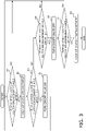
- FIG. 2 is a configuration diagram schematically illustrating a configuration of a power transmission device 2 according to the first embodiment.
- the work vehicle 1 is a wheel loader.
- the work vehicle 1 is provided with the power transmission device 2, a power source 3, and a travel device 4.
- the power transmission device 2 is disposed between the power source 3 and the travel device 4.
- the power source 3 is, for example, an engine.
- the power transmission device illustrated in FIG. 2 is mounted to the work vehicle 1.
- the power transmission device 2 has a transmission 10, a torque converter device 20, a hydraulic circuit, and a controller 40.
- the transmission 10 is disposed between the torque converter device 20 and the travel device 4.
- the transmission 10 is coupled to the torque converter device 20 and transmits the power from the power source 3 transmitted through the torque converter device 20, to the travel device 4.
- the transmission 10 is an example of a hydraulic apparatus.
- the torque converter device 20 is disposed between the power source 3 and the transmission 10.
- the torque converter device 20 is coupled to an output shaft of the power source 3 and an input shaft of the transmission 10.
- the torque converter device 20 has a torque converter 21 and a lock-up clutch 22.
- the torque converter 21 includes an impeller, a turbine, and a stator.
- the lock-up clutch 22 is a hydraulic actuation-type clutch and can be switched between an engaged state and a disengaged state.
- the clutch pressure of the lock-up clutch 22 is adjusted with a lock-up clutch control valve 23.
- the lock-up clutch control valve 23 is controlled by the controller 40.
- the torque converter 21 transmits the power from the power source 3 to the transmission 10 using oil as a medium.
- the lock-up clutch 22 couples the impeller and the turbine of the torque converter 21 and transmits the power from the power source 3 to the transmission 10.
- the hydraulic circuit has first to eighth oil channels L1-L8, a first hydraulic pump 31, a first pressure control valve 32, a second pressure control valve 33, a second hydraulic pump 34, an on/off valve 35, a third pressure control valve 36, and an oil pan 37.
- the first oil channel L1 communicates with the first hydraulic pump 31 and the torque converter 21.
- the first oil channel L1 is an oil supply channel for supplying hydraulic fluid from the first hydraulic pump 31 to the torque converter 21.
- the first hydraulic pump 31 is driven by the power source 3.
- the first hydraulic pump 31 is a fixed displacement pump.
- a gear pump, for example, may be used as the first hydraulic pump 31.
- the first hydraulic pump 31 discharges hydraulic fluid taken in from the oil pan 37.
- the hydraulic fluid discharged by the first hydraulic pump 31 is supplied to the torque converter 21 through the first oil channel L1.
- the second oil channel L2 communicates with the torque converter 21 and the oil pan 37.
- the second oil channel L2 is a drain oil channel for draining hydraulic fluid from the torque converter 21.
- the hydraulic fluid drained from the torque converter 21 is returned to the oil pan 37 through the second oil channel L2.
- the first pressure control valve 32 is disposed in the second oil channel L2.
- the first pressure control valve 32 is a regulator valve for adjusting the pressure of the hydraulic fluid drained from the torque converter 21 so that the internal pressure of the torque converter 21 does not fall below a constant pressure.
- the third oil channel L3 communicates with the first oil channel L1 and the second oil channel L2.
- the third oil channel L3 is coupled to the first oil channel L1 at a connection point P1 and is coupled to the second oil channel L2 at a connection point P2.
- the connection point P1 is the upstream end of the third oil channel L3 and the connection point P2 is the downstream end of the third oil channel L3.
- the connection point P1 is positioned on the upstream side of the second pressure control valve 33 and the connection point P2 is positioned on the downstream side of the first pressure control valve 32.
- the second pressure control valve 33 is disposed in the third oil channel L3.
- the second pressure control valve 33 is a relief valve for adjusting the pressure of the hydraulic fluid supplied from the first hydraulic pump 31 so that the internal pressure of the torque converter 21 does not rise above a constant pressure.
- the second pressure control valve 33 functions as a pressure control valve for reducing the internal pressure of the torque converter 21 when the lock-up clutch 22 is in the engaged state.
- the second pressure control valve 33 is held in an open state by the controller 40 when the lock-up clutch 22 is in the engaged state.
- the fourth oil channel L4 communicates with the second hydraulic pump 34 and the transmission 10.
- the fourth oil channel L4 is an oil supply channel for supplying hydraulic fluid from the second hydraulic pump 34 to the transmission 10.
- the second hydraulic pump 34 is driven by the power source 3.
- the second hydraulic pump 34 discharges the hydraulic fluid taken in from the oil pan 37.
- the hydraulic fluid discharged by the second hydraulic pump 34 is supplied to the transmission 10 through the fourth oil channel L4.
- the fifth oil channel L5 communicates with the fourth oil channel L4, the sixth oil channel L6, and the lock-up clutch control valve 23.
- the fifth oil channel L5 is coupled to the fourth oil channel L4 at a connection point P3.
- the fifth oil channel L5 supplies, to the sixth oil channel L6, a portion of the hydraulic fluid supplied from the second hydraulic pump 34 to the fourth oil channel L4.
- the fifth oil channel L5 supplies, to the lock-up clutch control valve 23, a portion of the hydraulic fluid supplied from the second hydraulic pump 34 to the fourth oil channel L4.
- the sixth oil channel L6 communicates with the fifth oil channel L5 and the on/off valve 35.
- the sixth oil channel L6 is coupled to the fifth oil channel L5 at an orifice 38.
- the orifice 38 is positioned on the upstream side of the sixth oil channel L6.
- the sixth oil channel L6 supplies, to the on/off valve 35, a portion of the hydraulic fluid supplied from the second hydraulic pump 34 to the fifth oil channel L5 through the fourth oil channel L4.
- the on/off valve 35 can be switched between an ON-state (closed state) and an OFF-state (open state). The switching of the on/off valve 35 is controlled by the controller 40.
- the on/off valve 35 is an electromagnetic valve that can be switched between on and off by means of a control signal from the controller 40.
- the seventh oil channel L7 communicates with the sixth oil channel L6 and the second pressure control valve 33.
- the seventh oil channel L7 is coupled to the sixth oil channel L6 at a connection point P4.
- the connection point P4 is positioned on the upstream side of the on/off valve 35.
- the eighth oil channel L8 communicates with the first oil channel L1 and the fourth oil channel L4.
- the eighth oil channel L8 is coupled to the first oil channel L1 at the connection point P1 and is coupled to the fourth oil channel L4 at a connection point P5.
- the connection point P5 is positioned on the upstream side of the fourth oil channel L4, the fifth oil channel L5, and the connection point P3.
- the third pressure control valve 36 is disposed in the eighth oil channel L8.
- the third pressure control valve 36 is a regulator valve for adjusting the pressure of the hydraulic fluid that passes through the fourth oil channel L4.
- the controller 40 is a controller for controlling the entire power transmission device 2.
- the controller 40 controls the lock-up clutch control valve 23 and the on/off valve 35, etc.
- the controller 40 has a processor such as a CPU, and a memory (RAM, ROM, etc.) having programs stored therein.
- the memory stores a lockup clutch engaged vehicle speed, a lockup clutch disengaged vehicle speed, a constant ⁇ , and a constant ⁇ .
- the respective values of the lockup clutch engaged vehicle speed, the lockup clutch disengaged vehicle speed, the constant ⁇ , and the constant ⁇ are set to desired values as appropriate.
- the controller 40 outputs a clutch pressure command signal to the lock-up clutch control valve 23 and causes the lock-up clutch 22 to become engaged when an engagement condition of the lock-up clutch 22 is established.
- the vehicle speed of the work vehicle 1 exceeding the lock-up clutch engagement vehicle speed is used as the engagement condition of the lock-up clutch 22.
- the controller 40 outputs the clutch pressure command signal to the lock-up clutch control valve 23 and causes the lock-up clutch 22 to become disengaged when a disengagement condition of the lock-up clutch 22 is established.
- the vehicle speed of the work vehicle 1 falling below the lock-up clutch engagement vehicle speed is used as the disengagement condition of the lock-up clutch 22.
- the controller 40 causes the second pressure control valve 33 to open and close in response to the engagement and disengagement of the lock-up clutch 22.
- the controller 40 outputs the clutch pressure command signal to the lock-up clutch control valve 23 when the vehicle speed of the work vehicle 1 exceeds the lock-up clutch engagement vehicle speed.
- the controller 40 outputs a control signal to the on/off valve 35 and the on/off valve 35 switches to the ON-state.
- the second pressure control valve 33 is switched to the open state without increasing the hydraulic pressure in the seventh oil channel L7, and a portion of the hydraulic fluid supplied from the first hydraulic pump 31 to the torque converter 21 is returned to the oil pan 37 through the third oil channel L3 and the second oil channel L2 in order.
- the internal pressure (predetermined pressure) of the torque converter 21 when the lock-up clutch 22 is in the engaged state is preferably lower than the constant pressure and, while not limited in particular, is preferably of a degree that the inside of the torque converter 21 can be lubricated with the hydraulic fluid.
- the controller 40 causes the internal pressure of the torque converter 21 to decrease by setting the second pressure control valve 33 to the open state when the lock-up clutch 22 is in the engaged state.
- the controller 40 outputs a control signal to the on/off valve 35 before disengaging the lock-up clutch 22 and switches the on/off valve 35 to the OFF-state.
- the second pressure control valve 33 is switched to the closed state without the hydraulic pressure of the seventh oil channel L7 decreasing, and the hydraulic pressure of the third oil channel L3 is adjusted by the second pressure control valve 33.
- the internal pressure of the torque converter 21 recovers to the constant pressure.
- the controller 40 raises the internal pressure of the torque converter 21 to the constant pressure by setting the second pressure control valve 33 to the closed state.
- FIG. 3 is a flow chart for explaining a power transmission method of the torque converter device 20.
- step S1 the controller 40 determines whether the vehicle speed of the work vehicle 1 has exceeded the lock-up clutch engagement vehicle speed. If the vehicle speed of the work vehicle 1 has exceeded the lock-up clutch engagement vehicle speed, the processing advances to step S2. If the vehicle speed of the work vehicle 1 does not exceed the lock-up clutch engagement vehicle speed, the processing of step S1 is repeated.
- step S2 the controller 40 outputs the clutch pressure command signal to the lock-up clutch control valve 23 and causes the lock-up clutch 22 to become engaged.
- step S3 the controller 40 determines whether the vehicle speed of the work vehicle 1 has exceeded a value derived by adding the constant ⁇ to the lock-up clutch engagement vehicle speed. If the vehicle speed of the work vehicle 1 has exceeded the value derived by adding the constant ⁇ to the lock-up clutch engagement vehicle speed, the processing advances to step S4. If the vehicle speed of the work vehicle 1 does not exceed the value derived by adding the constant ⁇ to the lock-up clutch engagement vehicle speed, the processing advances to step S5.
- step S4 the controller 40 outputs a control signal to the on/off valve 35 and switches the on/off valve 35 to the ON-state (closed state) in step S4. Consequently, as indicated above, the second pressure control valve 33 is switched to the open state and the internal pressure of the torque converter 21 is reduced.
- step S4 the processing returns to step S1.
- step S5 the controller 40 determines, in step S5, whether the vehicle speed of the work vehicle 1 has fallen below the value derived by adding the constant ⁇ to the lock-up clutch disengagement vehicle speed. If the vehicle speed of the work vehicle 1 has fallen below the value derived by adding the constant ⁇ to the lock-up clutch disengagement vehicle speed, the processing advances to step S6. If the vehicle speed of the work vehicle 1 has not fallen below the value derived by adding the constant ⁇ to the lock-up clutch disengagement vehicle speed, the processing returns to step S1.
- step S6 the controller 40 outputs, in step S6, a control signal to the on/off valve 35 and switches the on/off valve 35 to the OFF-state (open state). Consequently, as indicated above, the second pressure control valve 33 is switched to the closed state and the internal pressure of the torque converter 21 rises to the constant pressure.
- step S7 the controller 40 determines whether the vehicle speed of the work vehicle 1 has fallen below the lock-up clutch disengagement vehicle speed. If the vehicle speed of the work vehicle 1 has fallen below the lock-up clutch disengagement vehicle speed, the processing advances to step S8. If the vehicle speed of the work vehicle 1 has not fallen below the lock-up clutch disengagement vehicle speed, the processing returns to step S1.
- step S8 the controller 40 outputs the clutch pressure command signal to the lock-up clutch control valve 23 and causes the lock-up clutch 22 to become disengaged.
- a power transmission device 2a according to a second embodiment will be explained.
- the power transmission device 2a according to the present embodiment is mounted in a similar work vehicle as the work vehicle 1 according to the first embodiment.
- FIG. 4 is a configuration diagram schematically illustrating a configuration of the power transmission device 2a according to the second embodiment.
- the power transmission device 2a differs from the power transmission device 2 according to the first embodiment in that a seventh oil channel 7a communicates with the sixth oil channel L6 and the first pressure control valve 32. Said difference will mainly be explained hereinbelow.
- the seventh oil channel L7a communicates with the sixth oil channel L6 and the first pressure control valve 32.
- the seventh oil channel L7a is coupled to the sixth oil channel L6 at the connection point P4.
- the connection point P4 is positioned on the upstream side of the on/off valve 35.
- the controller 40 causes the first pressure control valve 32 to open and close in response to the engagement and disengagement of the lock-up clutch 22.
- the controller 40 issues an engagement command to the lock-up clutch 22 when the vehicle speed of the work vehicle 1 exceeds the lock-up clutch engagement vehicle speed.
- the controller 40 outputs a control signal to the on/off valve 35 and the on/off valve 35 switches to the ON-state. Consequently, the pressure of the seventh oil channel 7a increase and the first pressure control valve 32 is switched to the open state, and the hydraulic fluid drained from the torque converter 21 is returned quickly through the second oil channel L2 to the oil pan 37.
- loss of horsepower of the first hydraulic pump is suppressed because the internal pressure of the torque converter 21 is reduced to a predetermined pressure that is lower than the constant pressure.
- the controller 40 causes the internal pressure of the torque converter 21 to decrease by setting the first pressure control valve 32 to the open state when the lock-up clutch 22 is in the engaged state.
- the controller 40 outputs a control signal to the on/off valve 35 before disengaging the lock-up clutch 22 and switches the on/off valve 35 to the OFF-state.
- the pressure of the seventh oil channel 7a decreases and the first pressure control valve 32 is switched to the closed state, and the hydraulic pressure of the second oil channel L2 is adjusted by the first pressure control valve 32.
- the internal pressure of the torque converter 21 recovers to the constant pressure.
- the controller 40 raises the internal pressure of the torque converter 21 to the constant pressure by setting the first pressure control valve 32 to the closed state.
- the power transmission method of the torque converter device 20 is the same as explained with the flow chart in FIG. 3 .
- the second pressure control valve 33 for holding the internal pressure of the torque converter 21 at a constant pressure is used as a pressure adjustment valve for reducing the internal pressure of the torque converter 21 when the lock-up clutch 22 is in the engaged state.
- the first pressure control valve 32 for holding the internal pressure of the torque converter 21 at a constant pressure is used as a pressure adjustment valve for reducing the internal pressure of the torque converter 21 when the lock-up clutch 22 is in the engaged state.
- a pressure adjustment valve for reducing the internal pressure of the torque converter 21 may be provided separately from the first and second pressure controls valves 32 and 33. In this case, the pressure adjustment valve is disposed in the second oil channel L2 or in the third oil channel L3.
- the pressure adjustment valve When disposing the pressure adjustment valve in the second oil channel L2, the pressure adjustment valve is disposed on the upstream side of the first pressure control valve 32. When disposing the pressure adjustment valve in the third oil channel L3, the pressure adjustment valve is disposed on the upstream side of the second pressure control valve 33.
Landscapes
- Engineering & Computer Science (AREA)
- General Engineering & Computer Science (AREA)
- Mechanical Engineering (AREA)
- Chemical & Material Sciences (AREA)
- Combustion & Propulsion (AREA)
- Transportation (AREA)
- Control Of Fluid Gearings (AREA)
- Physics & Mathematics (AREA)
- Fluid Mechanics (AREA)
Abstract
Description
- The present invention relates to a power transmission device and a power transmission method.
- Conventionally, a work vehicle (such as a wheel loader or the like) is known that is provided with a torque converter device having a torque converter and a lock-up clutch. In the torque converter device, power from the engine is transmitted to a travel device through the torque converter if the lock-up clutch is in a disengaged state and is transmitted to the travel device through the lock-up clutch if the lock-up clutch is in an engaged state (see Patent Document No. 1).
- Patent Document No. 1: International Publication No.
WO 2011-099568 - The internal pressure of the torque converter increases even while the lock-up clutch is in the engaged state in Patent Document No. 1. In this case, the loss of horsepower in the hydraulic pump increases because there is a need to continually maintain the discharge pressure of the hydraulic pump at a high level.
- An object of the present disclosure is to provide a power transmission device and a power transmission method that can suppress the loss of horsepower in a hydraulic pump.
- A power transmission device according to the present disclosure is disposed between a power source and a travel device, and comprises a torque converter device, a first hydraulic pump, a first oil channel, a second oil channel, a third oil channel, a pressure control valve, and a controller. The torque converter device includes a torque converter and a lock-up clutch and transmits power from the power source to the travel device. The first hydraulic pump is driven by the power source. The first oil channel supplies hydraulic fluid from the first hydraulic pump to the torque converter. The second oil channel drains hydraulic fluid from the torque converter. The third oil channel communicates with the first oil channel and the second oil channel. The pressure control valve is disposed in the second oil channel or the third oil channel. The controller causes the pressure control valve to open and close. The controller sets the pressure control valve to an open state when the lock-up clutch is in an engaged state.
- According to the present disclosure, there can be provided a power transmission device and a power transmission method that can suppress loss of horsepower in a hydraulic pump.
-
-
FIG. 1 is a side view of a work vehicle according to an embodiment. -
FIG. 2 is a hydraulic circuit diagram of a power transmission system according to a first embodiment. -
FIG. 3 is a flow chart for explaining a power transmission method according to the first embodiment. -
FIG. 4 is a hydraulic circuit diagram of the power transmission system according to a second embodiment. - An embodiment of the power transmission device according to the present disclosure will be explained with reference to the drawings. The power transmission device according to the present disclosure is mounted in a work vehicle. The work vehicle may be, for example, a wheel loader, a dump truck, a bulldozer, a forklift, or the like but is not limited as such.
-
FIG. 1 is a side view of awork vehicle 1 according to the first embodiment.FIG. 2 is a configuration diagram schematically illustrating a configuration of apower transmission device 2 according to the first embodiment. - The
work vehicle 1 according to the present embodiment is a wheel loader. Thework vehicle 1 is provided with thepower transmission device 2, apower source 3, and atravel device 4. Thepower transmission device 2 is disposed between thepower source 3 and thetravel device 4. Thepower source 3 is, for example, an engine. - The power transmission device illustrated in
FIG. 2 is mounted to thework vehicle 1. - The
power transmission device 2 has atransmission 10, atorque converter device 20, a hydraulic circuit, and acontroller 40. - The
transmission 10 is disposed between thetorque converter device 20 and thetravel device 4. Thetransmission 10 is coupled to thetorque converter device 20 and transmits the power from thepower source 3 transmitted through thetorque converter device 20, to thetravel device 4. In the present embodiment, thetransmission 10 is an example of a hydraulic apparatus. - The
torque converter device 20 is disposed between thepower source 3 and thetransmission 10. Thetorque converter device 20 is coupled to an output shaft of thepower source 3 and an input shaft of thetransmission 10. - The
torque converter device 20 has atorque converter 21 and a lock-up clutch 22. Thetorque converter 21 includes an impeller, a turbine, and a stator. The lock-up clutch 22 is a hydraulic actuation-type clutch and can be switched between an engaged state and a disengaged state. The clutch pressure of the lock-up clutch 22 is adjusted with a lock-upclutch control valve 23. The lock-upclutch control valve 23 is controlled by thecontroller 40. - When the lock-
up clutch 22 is in the disengaged state, thetorque converter 21 transmits the power from thepower source 3 to thetransmission 10 using oil as a medium. When the lock-upclutch 22 is in the engaged state, the lock-upclutch 22 couples the impeller and the turbine of thetorque converter 21 and transmits the power from thepower source 3 to thetransmission 10. - The hydraulic circuit has first to eighth oil channels L1-L8, a first
hydraulic pump 31, a firstpressure control valve 32, a secondpressure control valve 33, a secondhydraulic pump 34, an on/offvalve 35, a thirdpressure control valve 36, and anoil pan 37. - The first oil channel L1 communicates with the first
hydraulic pump 31 and thetorque converter 21. The first oil channel L1 is an oil supply channel for supplying hydraulic fluid from the firsthydraulic pump 31 to thetorque converter 21. - The first
hydraulic pump 31 is driven by thepower source 3. The firsthydraulic pump 31 is a fixed displacement pump. A gear pump, for example, may be used as the firsthydraulic pump 31. The firsthydraulic pump 31 discharges hydraulic fluid taken in from theoil pan 37. The hydraulic fluid discharged by the firsthydraulic pump 31 is supplied to thetorque converter 21 through the first oil channel L1. - The second oil channel L2 communicates with the
torque converter 21 and theoil pan 37. The second oil channel L2 is a drain oil channel for draining hydraulic fluid from thetorque converter 21. The hydraulic fluid drained from thetorque converter 21 is returned to theoil pan 37 through the second oil channel L2. - The first
pressure control valve 32 is disposed in the second oil channel L2. The firstpressure control valve 32 is a regulator valve for adjusting the pressure of the hydraulic fluid drained from thetorque converter 21 so that the internal pressure of thetorque converter 21 does not fall below a constant pressure. - The third oil channel L3 communicates with the first oil channel L1 and the second oil channel L2. The third oil channel L3 is coupled to the first oil channel L1 at a connection point P1 and is coupled to the second oil channel L2 at a connection point P2. The connection point P1 is the upstream end of the third oil channel L3 and the connection point P2 is the downstream end of the third oil channel L3. The connection point P1 is positioned on the upstream side of the second
pressure control valve 33 and the connection point P2 is positioned on the downstream side of the firstpressure control valve 32. - The second
pressure control valve 33 is disposed in the third oil channel L3. The secondpressure control valve 33 is a relief valve for adjusting the pressure of the hydraulic fluid supplied from the firsthydraulic pump 31 so that the internal pressure of thetorque converter 21 does not rise above a constant pressure. - In the present embodiment, the second
pressure control valve 33 functions as a pressure control valve for reducing the internal pressure of thetorque converter 21 when the lock-up clutch 22 is in the engaged state. The secondpressure control valve 33 is held in an open state by thecontroller 40 when the lock-up clutch 22 is in the engaged state. - The fourth oil channel L4 communicates with the second
hydraulic pump 34 and thetransmission 10. The fourth oil channel L4 is an oil supply channel for supplying hydraulic fluid from the secondhydraulic pump 34 to thetransmission 10. - The second
hydraulic pump 34 is driven by thepower source 3. The secondhydraulic pump 34 discharges the hydraulic fluid taken in from theoil pan 37. The hydraulic fluid discharged by the secondhydraulic pump 34 is supplied to thetransmission 10 through the fourth oil channel L4. - The fifth oil channel L5 communicates with the fourth oil channel L4, the sixth oil channel L6, and the lock-up
clutch control valve 23. The fifth oil channel L5 is coupled to the fourth oil channel L4 at a connection point P3. The fifth oil channel L5 supplies, to the sixth oil channel L6, a portion of the hydraulic fluid supplied from the secondhydraulic pump 34 to the fourth oil channel L4. The fifth oil channel L5 supplies, to the lock-upclutch control valve 23, a portion of the hydraulic fluid supplied from the secondhydraulic pump 34 to the fourth oil channel L4. - The sixth oil channel L6 communicates with the fifth oil channel L5 and the on/off
valve 35. The sixth oil channel L6 is coupled to the fifth oil channel L5 at anorifice 38. Theorifice 38 is positioned on the upstream side of the sixth oil channel L6. The sixth oil channel L6 supplies, to the on/offvalve 35, a portion of the hydraulic fluid supplied from the secondhydraulic pump 34 to the fifth oil channel L5 through the fourth oil channel L4. - The on/off
valve 35 can be switched between an ON-state (closed state) and an OFF-state (open state). The switching of the on/offvalve 35 is controlled by thecontroller 40. In the present embodiment, the on/offvalve 35 is an electromagnetic valve that can be switched between on and off by means of a control signal from thecontroller 40. When the lock-up clutch 22 is in the engaged state, the on/offvalve 35 is switched to the ON-state and the hydraulic pressure of the sixth oil channel L6 is maintained at a high state. When the lock-up clutch 22 is in the disengaged state, the on/offvalve 35 is switched to the OFF-state and the hydraulic pressure of the sixth oil channel L6 is maintained at a low state. - The seventh oil channel L7 communicates with the sixth oil channel L6 and the second
pressure control valve 33. The seventh oil channel L7 is coupled to the sixth oil channel L6 at a connection point P4. The connection point P4 is positioned on the upstream side of the on/offvalve 35. When the lock-up clutch 22 is in the engaged state, the on/offvalve 35 is switched to the ON-state and the hydraulic pressure of the seventh oil channel L7 is maintained at a high state. As a result, the secondpressure control valve 33 is held in the open state. When the lock-up clutch 22 is in the disengaged state, the on/offvalve 35 is switched to the OFF-state and the hydraulic pressure of the seventh oil channel L7 is maintained at a low state. As a result, the secondpressure control valve 33 is actuated to open and close so that the internal pressure of thetorque converter 21 is kept at a constant pressure. - The eighth oil channel L8 communicates with the first oil channel L1 and the fourth oil channel L4. The eighth oil channel L8 is coupled to the first oil channel L1 at the connection point P1 and is coupled to the fourth oil channel L4 at a connection point P5. The connection point P5 is positioned on the upstream side of the fourth oil channel L4, the fifth oil channel L5, and the connection point P3. The third
pressure control valve 36 is disposed in the eighth oil channel L8. The thirdpressure control valve 36 is a regulator valve for adjusting the pressure of the hydraulic fluid that passes through the fourth oil channel L4. - The
controller 40 is a controller for controlling the entirepower transmission device 2. Thecontroller 40 controls the lock-upclutch control valve 23 and the on/offvalve 35, etc. Thecontroller 40 has a processor such as a CPU, and a memory (RAM, ROM, etc.) having programs stored therein. The memory stores a lockup clutch engaged vehicle speed, a lockup clutch disengaged vehicle speed, a constant α, and a constant β. The respective values of the lockup clutch engaged vehicle speed, the lockup clutch disengaged vehicle speed, the constant α, and the constant β are set to desired values as appropriate. - The
controller 40 outputs a clutch pressure command signal to the lock-upclutch control valve 23 and causes the lock-up clutch 22 to become engaged when an engagement condition of the lock-up clutch 22 is established. In the present embodiment, the vehicle speed of thework vehicle 1 exceeding the lock-up clutch engagement vehicle speed is used as the engagement condition of the lock-upclutch 22. Thecontroller 40 outputs the clutch pressure command signal to the lock-upclutch control valve 23 and causes the lock-up clutch 22 to become disengaged when a disengagement condition of the lock-up clutch 22 is established. In the present embodiment, the vehicle speed of thework vehicle 1 falling below the lock-up clutch engagement vehicle speed is used as the disengagement condition of the lock-upclutch 22. - The
controller 40 causes the secondpressure control valve 33 to open and close in response to the engagement and disengagement of the lock-upclutch 22. - Specifically, the
controller 40 outputs the clutch pressure command signal to the lock-upclutch control valve 23 when the vehicle speed of thework vehicle 1 exceeds the lock-up clutch engagement vehicle speed. When the engagement of the lock-up clutch 22 is finished and the vehicle speed of thework vehicle 1 exceeds a value derived by adding the constant α to the lock-up clutch engagement vehicle speed, thecontroller 40 outputs a control signal to the on/offvalve 35 and the on/offvalve 35 switches to the ON-state. As a result, the secondpressure control valve 33 is switched to the open state without increasing the hydraulic pressure in the seventh oil channel L7, and a portion of the hydraulic fluid supplied from the firsthydraulic pump 31 to thetorque converter 21 is returned to theoil pan 37 through the third oil channel L3 and the second oil channel L2 in order. As a result, loss of horsepower of the firsthydraulic pump 31 is suppressed because the internal pressure of thetorque converter 21 is reduced to a predetermined pressure that is lower than the constant pressure. The internal pressure (predetermined pressure) of thetorque converter 21 when the lock-up clutch 22 is in the engaged state is preferably lower than the constant pressure and, while not limited in particular, is preferably of a degree that the inside of thetorque converter 21 can be lubricated with the hydraulic fluid. - In this way, the
controller 40 causes the internal pressure of thetorque converter 21 to decrease by setting the secondpressure control valve 33 to the open state when the lock-up clutch 22 is in the engaged state. - However, when the vehicle speed of the
work vehicle 1 falls below a value derived by adding the constant β to the lock-up clutch disengagement vehicle speed, thecontroller 40 outputs a control signal to the on/offvalve 35 before disengaging the lock-upclutch 22 and switches the on/offvalve 35 to the OFF-state. As a result, the secondpressure control valve 33 is switched to the closed state without the hydraulic pressure of the seventh oil channel L7 decreasing, and the hydraulic pressure of the third oil channel L3 is adjusted by the secondpressure control valve 33. As a result, the internal pressure of thetorque converter 21 recovers to the constant pressure. - In this way, when the vehicle speed of the
work vehicle 1 falls below the value derived by adding the constant β to the lock-up clutch disengagement vehicle speed, thecontroller 40 raises the internal pressure of thetorque converter 21 to the constant pressure by setting the secondpressure control valve 33 to the closed state. -
FIG. 3 is a flow chart for explaining a power transmission method of thetorque converter device 20. - In step S1, the
controller 40 determines whether the vehicle speed of thework vehicle 1 has exceeded the lock-up clutch engagement vehicle speed. If the vehicle speed of thework vehicle 1 has exceeded the lock-up clutch engagement vehicle speed, the processing advances to step S2. If the vehicle speed of thework vehicle 1 does not exceed the lock-up clutch engagement vehicle speed, the processing of step S1 is repeated. - In step S2, the
controller 40 outputs the clutch pressure command signal to the lock-upclutch control valve 23 and causes the lock-up clutch 22 to become engaged. - In step S3, the
controller 40 determines whether the vehicle speed of thework vehicle 1 has exceeded a value derived by adding the constant α to the lock-up clutch engagement vehicle speed. If the vehicle speed of thework vehicle 1 has exceeded the value derived by adding the constant α to the lock-up clutch engagement vehicle speed, the processing advances to step S4. If the vehicle speed of thework vehicle 1 does not exceed the value derived by adding the constant α to the lock-up clutch engagement vehicle speed, the processing advances to step S5. - When the processing advances from step S3 to step S4, the
controller 40 outputs a control signal to the on/offvalve 35 and switches the on/offvalve 35 to the ON-state (closed state) in step S4. Consequently, as indicated above, the secondpressure control valve 33 is switched to the open state and the internal pressure of thetorque converter 21 is reduced. When step S4 is completed, the processing returns to step S1. - When the processing advances from step S3 to step S5, the
controller 40 determines, in step S5, whether the vehicle speed of thework vehicle 1 has fallen below the value derived by adding the constant β to the lock-up clutch disengagement vehicle speed. If the vehicle speed of thework vehicle 1 has fallen below the value derived by adding the constant β to the lock-up clutch disengagement vehicle speed, the processing advances to step S6. If the vehicle speed of thework vehicle 1 has not fallen below the value derived by adding the constant β to the lock-up clutch disengagement vehicle speed, the processing returns to step S1. - When the processing advances from step S5 to step S6, the
controller 40 outputs, in step S6, a control signal to the on/offvalve 35 and switches the on/offvalve 35 to the OFF-state (open state). Consequently, as indicated above, the secondpressure control valve 33 is switched to the closed state and the internal pressure of thetorque converter 21 rises to the constant pressure. - In step S7, the
controller 40 determines whether the vehicle speed of thework vehicle 1 has fallen below the lock-up clutch disengagement vehicle speed. If the vehicle speed of thework vehicle 1 has fallen below the lock-up clutch disengagement vehicle speed, the processing advances to step S8. If the vehicle speed of thework vehicle 1 has not fallen below the lock-up clutch disengagement vehicle speed, the processing returns to step S1. - In step S8, the
controller 40 outputs the clutch pressure command signal to the lock-upclutch control valve 23 and causes the lock-up clutch 22 to become disengaged. - A
power transmission device 2a according to a second embodiment will be explained. Thepower transmission device 2a according to the present embodiment is mounted in a similar work vehicle as thework vehicle 1 according to the first embodiment. -
FIG. 4 is a configuration diagram schematically illustrating a configuration of thepower transmission device 2a according to the second embodiment. - The
power transmission device 2a differs from thepower transmission device 2 according to the first embodiment in that a seventh oil channel 7a communicates with the sixth oil channel L6 and the firstpressure control valve 32. Said difference will mainly be explained hereinbelow. - The seventh oil channel L7a communicates with the sixth oil channel L6 and the first
pressure control valve 32. The seventh oil channel L7a is coupled to the sixth oil channel L6 at the connection point P4. The connection point P4 is positioned on the upstream side of the on/offvalve 35. When the lock-up clutch 22 is in the engaged state, the on/offvalve 35 is switched to the ON-state and the hydraulic pressure of the seventh oil channel L7a is maintained at a high state. As a result, the firstpressure control valve 32 is held in the open state. When the lock-up clutch 22 is in the disengaged state, the on/offvalve 35 is switched to the OFF-state and the hydraulic pressure of the seventh oil channel L7a is maintained at a low state. As a result, the firstpressure control valve 32 is actuated to open and close so that the internal pressure of thetorque converter 21 is kept at the constant pressure. - The
controller 40 causes the firstpressure control valve 32 to open and close in response to the engagement and disengagement of the lock-upclutch 22. - Specifically, the
controller 40 issues an engagement command to the lock-up clutch 22 when the vehicle speed of thework vehicle 1 exceeds the lock-up clutch engagement vehicle speed. When the engagement of the lock-up clutch 22 is finished and the vehicle speed of thework vehicle 1 exceeds the value derived by adding the constant α to the lock-up clutch engagement vehicle speed, thecontroller 40 outputs a control signal to the on/offvalve 35 and the on/offvalve 35 switches to the ON-state. Consequently, the pressure of the seventh oil channel 7a increase and the firstpressure control valve 32 is switched to the open state, and the hydraulic fluid drained from thetorque converter 21 is returned quickly through the second oil channel L2 to theoil pan 37. As a result, loss of horsepower of the first hydraulic pump is suppressed because the internal pressure of thetorque converter 21 is reduced to a predetermined pressure that is lower than the constant pressure. - In this way, the
controller 40 causes the internal pressure of thetorque converter 21 to decrease by setting the firstpressure control valve 32 to the open state when the lock-up clutch 22 is in the engaged state. - However, when the vehicle speed of the
work vehicle 1 falls below the value derived by adding the constant β to the lock-up clutch disengagement vehicle speed, thecontroller 40 outputs a control signal to the on/offvalve 35 before disengaging the lock-upclutch 22 and switches the on/offvalve 35 to the OFF-state. As a result, the pressure of the seventh oil channel 7a decreases and the firstpressure control valve 32 is switched to the closed state, and the hydraulic pressure of the second oil channel L2 is adjusted by the firstpressure control valve 32. As a result, the internal pressure of thetorque converter 21 recovers to the constant pressure. - In this way, when the vehicle speed of the
work vehicle 1 falls below the value derived by adding the constant β to the lock-up clutch disengagement vehicle speed, thecontroller 40 raises the internal pressure of thetorque converter 21 to the constant pressure by setting the firstpressure control valve 32 to the closed state. - The power transmission method of the
torque converter device 20 is the same as explained with the flow chart inFIG. 3 . - Although embodiments of the present invention have been described so far, the present invention is not limited to the above embodiments and various modifications may be made within the scope of the invention.
- In the first embodiment, the second
pressure control valve 33 for holding the internal pressure of thetorque converter 21 at a constant pressure is used as a pressure adjustment valve for reducing the internal pressure of thetorque converter 21 when the lock-up clutch 22 is in the engaged state. In the second embodiment, the firstpressure control valve 32 for holding the internal pressure of thetorque converter 21 at a constant pressure, is used as a pressure adjustment valve for reducing the internal pressure of thetorque converter 21 when the lock-up clutch 22 is in the engaged state. However, a pressure adjustment valve for reducing the internal pressure of thetorque converter 21 may be provided separately from the first and second pressure controlsvalves pressure control valve 32. When disposing the pressure adjustment valve in the third oil channel L3, the pressure adjustment valve is disposed on the upstream side of the secondpressure control valve 33. -
- 1:
- Work vehicle
- 2, 2a:
- Power transmission device
- 3:
- Power source
- 4:
- Travel device
- 10:
- Transmission
- 20:
- Torque converter device
- 21:
- Torque converter
- 22:
- Lock-up clutch
- 23:
- Lock-up clutch control valve
- L1-L8:
- First to eighth oil channels
- 31:
- First hydraulic pump
- 32:
- First pressure control valve
- 33:
- Second pressure control valve
- 34:
- Second hydraulic pump
- 35:
- On/off valve
- 36:
- Third pressure control valve
- 37:
- Oil pan
- 38:
- Orifice
- 40:
- Controller
Claims (5)
- A power transmission device disposed between a power source and a travel device, the power transmission device comprising:a torque converter device including a torque converter and a lock-up clutch and configured to transmit power from the power source to the travel device;a first hydraulic pump driven by the power source;a first oil channel for supplying hydraulic fluid from the first hydraulic pump to the torque converter;a second oil channel for draining hydraulic fluid from the torque converter;a third oil channel that communicates with the first oil channel and the second oil channel;a pressure control valve disposed in the second oil channel or the third oil channel; anda controller configured to cause the pressure control valve to open and close,wherein
the controller sets the pressure control valve to an open state when the lock-up clutch is in an engaged state. - The power transmission device according to claim 1, further comprisinga second hydraulic pump driven by the power source;a fourth oil channel for supplying hydraulic fluid from the second hydraulic pump to a hydraulic apparatus;a fifth oil channel that communicates with the fourth oil channel and an orifice;a sixth oil channel that communicates with the fifth oil channel and an on/off valve; anda seventh oil channel that communicates with the sixth oil channel and the pressure control valve,whereinthe pressure control valve is disposed in the third oil channel, andthe controller sets the pressure control valve to the open state by setting the on/off valve to an ON-state.
- The power transmission device according to claim 1, further comprisinga second hydraulic pump driven by the power source;a fourth oil channel for supplying hydraulic fluid from the second hydraulic pump to a hydraulic apparatus;a fifth oil channel that communicates with the fourth oil channel and an orifice;a sixth oil channel that communicates with the fifth oil channel and an on/off valve; anda seventh oil channel that communicates with the sixth oil channel and the pressure control valve,whereinthe pressure control valve is disposed in the second oil channel,
andthe controller sets the pressure control valve to the open state by setting the on/off valve to an ON-state. - The power transmission device according to claim 2 or 3, wherein the hydraulic apparatus is a transmission.
- A power transmission method performed between a power source and a travel device, the method comprising:a step for causing a lock-up clutch to be engaged in a torque converter device that has a torque converter and the lock-up clutch and transmits power from the power source to the travel device; anda step for setting a pressure control valve to an open state, the pressure control valve being disposed in a second oil channel or a third oil channel among a first oil channel for supplying hydraulic fluid from a first hydraulic pump driven by the power source to the torque converter, the second oil channel for draining hydraulic fluid from the torque converter, and the third oil channel that communicates with the first oil channel and the second oil channel.
Applications Claiming Priority (2)
| Application Number | Priority Date | Filing Date | Title |
|---|---|---|---|
| JP2020053170A JP7545222B2 (en) | 2020-03-24 | 2020-03-24 | Power transmission device and power transmission method |
| PCT/JP2021/001506 WO2021192540A1 (en) | 2020-03-24 | 2021-01-18 | Power transmission device and power transmission method |
Publications (3)
| Publication Number | Publication Date |
|---|---|
| EP4056879A1 true EP4056879A1 (en) | 2022-09-14 |
| EP4056879A4 EP4056879A4 (en) | 2023-01-25 |
| EP4056879B1 EP4056879B1 (en) | 2025-03-05 |
Family
ID=77887287
Family Applications (1)
| Application Number | Title | Priority Date | Filing Date |
|---|---|---|---|
| EP21774613.0A Active EP4056879B1 (en) | 2020-03-24 | 2021-01-18 | Power transmission device and power transmission method |
Country Status (5)
| Country | Link |
|---|---|
| US (1) | US11971098B2 (en) |
| EP (1) | EP4056879B1 (en) |
| JP (1) | JP7545222B2 (en) |
| CN (1) | CN114829807B (en) |
| WO (1) | WO2021192540A1 (en) |
Family Cites Families (26)
| Publication number | Priority date | Publication date | Assignee | Title |
|---|---|---|---|---|
| US4448293A (en) * | 1982-02-19 | 1984-05-15 | Kabushiki Kaisha Komatsu Seisakusho | Pressure-responsive control for a power train of the type having a torque converter equipped with a lockup clutch |
| SU1039749A2 (en) * | 1982-05-18 | 1983-09-07 | Могилевский Машиностроительный Институт | Hydraulic system for controlling hydromechanical transmission |
| JPH0573354U (en) * | 1992-03-12 | 1993-10-08 | 小松メック株式会社 | Lockup control device for torque converter |
| JP3925987B2 (en) * | 1997-05-27 | 2007-06-06 | 富士重工業株式会社 | Hydraulic control device for continuously variable transmission |
| US6371885B1 (en) * | 1999-04-01 | 2002-04-16 | Komatsu Ltd. | Working vehicle and vehicle speed control method thereof, variable power engine and power setting method thereof, and vehicle with variable power engine and power control method thereof |
| JP4454063B2 (en) * | 1999-05-21 | 2010-04-21 | 富士重工業株式会社 | Clutch control device for continuously variable transmission |
| JP3539313B2 (en) | 1999-10-18 | 2004-07-07 | 日産自動車株式会社 | Lockup control device for torque converter |
| JP4429464B2 (en) * | 2000-03-27 | 2010-03-10 | 株式会社小松製作所 | Apparatus for detecting internal pressure of fluid-mechanical power conversion device and torque converter including the same |
| JP4760060B2 (en) * | 2005-03-04 | 2011-08-31 | トヨタ自動車株式会社 | Hydraulic control device for fluid transmission with lockup clutch for vehicle |
| JP2007016870A (en) * | 2005-07-06 | 2007-01-25 | Fuji Heavy Ind Ltd | Torque converter |
| JP5145759B2 (en) * | 2007-04-25 | 2013-02-20 | トヨタ自動車株式会社 | Hydraulic control device |
| CN101809329B (en) * | 2007-09-26 | 2013-03-27 | 日立建机株式会社 | Hydraulic pressure supply device for industrial vehicle |
| JP5481023B2 (en) | 2007-10-25 | 2014-04-23 | 株式会社小松製作所 | Work vehicle and control method of work vehicle |
| JP5045385B2 (en) * | 2007-11-16 | 2012-10-10 | トヨタ自動車株式会社 | Hydraulic control device for lock-up clutch |
| JP5038943B2 (en) * | 2008-03-06 | 2012-10-03 | 富士重工業株式会社 | Hydraulic controller for torque converter |
| JP4605245B2 (en) * | 2008-04-24 | 2011-01-05 | トヨタ自動車株式会社 | Hydraulic control device |
| JP5390888B2 (en) | 2009-03-04 | 2014-01-15 | 株式会社小松製作所 | Lubricating oil control device for construction machinery |
| WO2011001841A1 (en) * | 2009-06-29 | 2011-01-06 | 本田技研工業株式会社 | Hydraulic control device for automatic transmission |
| CN101614270B (en) * | 2009-07-23 | 2011-06-22 | 大连兴龙液压有限公司 | Torque converter valves for bulldozers |
| CN201521616U (en) * | 2009-07-23 | 2010-07-07 | 大连兴龙液压有限公司 | hydraulic torque converter valve for bulldozer |
| CN101994825B (en) * | 2009-08-24 | 2014-04-30 | 上海华普国润汽车有限公司 | Hydraulic control device for hybrid power transmission |
| WO2011099568A1 (en) | 2010-02-10 | 2011-08-18 | 株式会社小松製作所 | Working vehicle and control method for working vehicle |
| JP5435145B2 (en) | 2010-10-19 | 2014-03-05 | トヨタ自動車株式会社 | Hydraulic control device for automatic transmission for vehicle |
| JP5106663B1 (en) * | 2011-08-11 | 2012-12-26 | 株式会社小松製作所 | Work vehicle |
| JP5900957B2 (en) * | 2012-03-23 | 2016-04-06 | 本田技研工業株式会社 | Hydraulic control device for automatic transmission for vehicle |
| DE102014201131A1 (en) * | 2014-01-22 | 2015-07-23 | Zf Friedrichshafen Ag | Transmission device with a hydraulic system |
-
2020
- 2020-03-24 JP JP2020053170A patent/JP7545222B2/en active Active
-
2021
- 2021-01-18 US US17/783,360 patent/US11971098B2/en active Active
- 2021-01-18 EP EP21774613.0A patent/EP4056879B1/en active Active
- 2021-01-18 WO PCT/JP2021/001506 patent/WO2021192540A1/en not_active Ceased
- 2021-01-18 CN CN202180007238.5A patent/CN114829807B/en active Active
Also Published As
| Publication number | Publication date |
|---|---|
| CN114829807A (en) | 2022-07-29 |
| JP2021152388A (en) | 2021-09-30 |
| JP7545222B2 (en) | 2024-09-04 |
| WO2021192540A1 (en) | 2021-09-30 |
| US20230016070A1 (en) | 2023-01-19 |
| EP4056879A4 (en) | 2023-01-25 |
| EP4056879B1 (en) | 2025-03-05 |
| US11971098B2 (en) | 2024-04-30 |
| CN114829807B (en) | 2024-04-12 |
Similar Documents
| Publication | Publication Date | Title |
|---|---|---|
| EP1881222B1 (en) | Method of operating a dual clutch transmission hydraulic power control system as well as dual clutch transmission hydraulic power control system | |
| KR102142337B1 (en) | Continuously variable transmission with a hydraulic control system | |
| US6364802B1 (en) | Hydraulic control system for a continuously variable transmission | |
| EP4056879B1 (en) | Power transmission device and power transmission method | |
| KR101229173B1 (en) | Supply pump | |
| CN105980747A (en) | Hydraulic control device and method for controlling same | |
| CN112283186B (en) | Hydraulic control system of automatic transmission and control method thereof | |
| US9334954B2 (en) | Method for controlling slip of a continuously variable transmission | |
| JP5935704B2 (en) | Hydraulic control device | |
| EP2405161A1 (en) | Lubricating oil supply control device for a construction machine | |
| US11965593B2 (en) | Damping pressure supply circuit for pulley pressure control valve | |
| JP2830525B2 (en) | Pump displacement control device for fluid working system | |
| JP2008267444A (en) | Transmission device equipped with hydraulic pressure control mechanism | |
| EP2798244B1 (en) | Method for controlling a continuously variable transmission with an electro-hydraulic control system | |
| KR102093113B1 (en) | Hydraulic apparatus for hybrid transmission | |
| JP2003517540A (en) | Automatic transmission | |
| CN114688113B (en) | Dosing pump hydraulic system of crane and control method thereof and crane | |
| JPH01279157A (en) | Device for controlling slip of torque converter | |
| KR100376858B1 (en) | pressure control system for automatic transmission | |
| KR100196793B1 (en) | Line pressure compensation method of clutch working of hydraulic control system | |
| KR101009838B1 (en) | Electronic proportional valve control device for hydraulic pump | |
| KR100211362B1 (en) | Line pressure reduction compensator for automatic transmission | |
| JP2017180629A (en) | Automatic transmission | |
| KR101438621B1 (en) | Line pressure increment control hydraulic pressure device | |
| KR20200061661A (en) | Binary hydraulic apparatus for transmission |
Legal Events
| Date | Code | Title | Description |
|---|---|---|---|
| STAA | Information on the status of an ep patent application or granted ep patent |
Free format text: STATUS: THE INTERNATIONAL PUBLICATION HAS BEEN MADE |
|
| PUAI | Public reference made under article 153(3) epc to a published international application that has entered the european phase |
Free format text: ORIGINAL CODE: 0009012 |
|
| STAA | Information on the status of an ep patent application or granted ep patent |
Free format text: STATUS: REQUEST FOR EXAMINATION WAS MADE |
|
| 17P | Request for examination filed |
Effective date: 20220609 |
|
| AK | Designated contracting states |
Kind code of ref document: A1 Designated state(s): AL AT BE BG CH CY CZ DE DK EE ES FI FR GB GR HR HU IE IS IT LI LT LU LV MC MK MT NL NO PL PT RO RS SE SI SK SM TR |
|
| REG | Reference to a national code |
Ref country code: DE Free format text: PREVIOUS MAIN CLASS: F16H0061140000 Ref country code: DE Ref legal event code: R079 Ref document number: 602021027221 Country of ref document: DE Free format text: PREVIOUS MAIN CLASS: F16H0061140000 Ipc: F16H0061000000 |
|
| A4 | Supplementary search report drawn up and despatched |
Effective date: 20221223 |
|
| RIC1 | Information provided on ipc code assigned before grant |
Ipc: F16H 61/14 20060101ALI20221220BHEP Ipc: F16H 61/00 20060101AFI20221220BHEP |
|
| DAV | Request for validation of the european patent (deleted) | ||
| DAX | Request for extension of the european patent (deleted) | ||
| GRAP | Despatch of communication of intention to grant a patent |
Free format text: ORIGINAL CODE: EPIDOSNIGR1 |
|
| STAA | Information on the status of an ep patent application or granted ep patent |
Free format text: STATUS: GRANT OF PATENT IS INTENDED |
|
| RIC1 | Information provided on ipc code assigned before grant |
Ipc: F16H 61/02 20060101ALI20240820BHEP Ipc: F16H 61/14 20060101ALI20240820BHEP Ipc: F16H 61/00 20060101AFI20240820BHEP |
|
| INTG | Intention to grant announced |
Effective date: 20240924 |
|
| GRAS | Grant fee paid |
Free format text: ORIGINAL CODE: EPIDOSNIGR3 |
|
| GRAA | (expected) grant |
Free format text: ORIGINAL CODE: 0009210 |
|
| STAA | Information on the status of an ep patent application or granted ep patent |
Free format text: STATUS: THE PATENT HAS BEEN GRANTED |
|
| AK | Designated contracting states |
Kind code of ref document: B1 Designated state(s): AL AT BE BG CH CY CZ DE DK EE ES FI FR GB GR HR HU IE IS IT LI LT LU LV MC MK MT NL NO PL PT RO RS SE SI SK SM TR |
|
| REG | Reference to a national code |
Ref country code: GB Ref legal event code: FG4D |
|
| REG | Reference to a national code |
Ref country code: CH Ref legal event code: EP |
|
| REG | Reference to a national code |
Ref country code: DE Ref legal event code: R096 Ref document number: 602021027221 Country of ref document: DE |
|
| REG | Reference to a national code |
Ref country code: IE Ref legal event code: FG4D |
|
| REG | Reference to a national code |
Ref country code: SE Ref legal event code: TRGR |
|
| PG25 | Lapsed in a contracting state [announced via postgrant information from national office to epo] |
Ref country code: RS Free format text: LAPSE BECAUSE OF FAILURE TO SUBMIT A TRANSLATION OF THE DESCRIPTION OR TO PAY THE FEE WITHIN THE PRESCRIBED TIME-LIMIT Effective date: 20250605 |
|
| PG25 | Lapsed in a contracting state [announced via postgrant information from national office to epo] |
Ref country code: FI Free format text: LAPSE BECAUSE OF FAILURE TO SUBMIT A TRANSLATION OF THE DESCRIPTION OR TO PAY THE FEE WITHIN THE PRESCRIBED TIME-LIMIT Effective date: 20250305 |
|
| REG | Reference to a national code |
Ref country code: NL Ref legal event code: MP Effective date: 20250305 |
|
| PG25 | Lapsed in a contracting state [announced via postgrant information from national office to epo] |
Ref country code: ES Free format text: LAPSE BECAUSE OF FAILURE TO SUBMIT A TRANSLATION OF THE DESCRIPTION OR TO PAY THE FEE WITHIN THE PRESCRIBED TIME-LIMIT Effective date: 20250305 |
|
| REG | Reference to a national code |
Ref country code: LT Ref legal event code: MG9D |
|
| PG25 | Lapsed in a contracting state [announced via postgrant information from national office to epo] |
Ref country code: NO Free format text: LAPSE BECAUSE OF FAILURE TO SUBMIT A TRANSLATION OF THE DESCRIPTION OR TO PAY THE FEE WITHIN THE PRESCRIBED TIME-LIMIT Effective date: 20250605 |
|
| PG25 | Lapsed in a contracting state [announced via postgrant information from national office to epo] |
Ref country code: HR Free format text: LAPSE BECAUSE OF FAILURE TO SUBMIT A TRANSLATION OF THE DESCRIPTION OR TO PAY THE FEE WITHIN THE PRESCRIBED TIME-LIMIT Effective date: 20250305 |
|
| PG25 | Lapsed in a contracting state [announced via postgrant information from national office to epo] |
Ref country code: LV Free format text: LAPSE BECAUSE OF FAILURE TO SUBMIT A TRANSLATION OF THE DESCRIPTION OR TO PAY THE FEE WITHIN THE PRESCRIBED TIME-LIMIT Effective date: 20250305 |
|
| PG25 | Lapsed in a contracting state [announced via postgrant information from national office to epo] |
Ref country code: GR Free format text: LAPSE BECAUSE OF FAILURE TO SUBMIT A TRANSLATION OF THE DESCRIPTION OR TO PAY THE FEE WITHIN THE PRESCRIBED TIME-LIMIT Effective date: 20250606 Ref country code: BG Free format text: LAPSE BECAUSE OF FAILURE TO SUBMIT A TRANSLATION OF THE DESCRIPTION OR TO PAY THE FEE WITHIN THE PRESCRIBED TIME-LIMIT Effective date: 20250305 |
|
| REG | Reference to a national code |
Ref country code: AT Ref legal event code: MK05 Ref document number: 1773184 Country of ref document: AT Kind code of ref document: T Effective date: 20250305 |
|
| PG25 | Lapsed in a contracting state [announced via postgrant information from national office to epo] |
Ref country code: NL Free format text: LAPSE BECAUSE OF FAILURE TO SUBMIT A TRANSLATION OF THE DESCRIPTION OR TO PAY THE FEE WITHIN THE PRESCRIBED TIME-LIMIT Effective date: 20250305 |
|
| PG25 | Lapsed in a contracting state [announced via postgrant information from national office to epo] |
Ref country code: SM Free format text: LAPSE BECAUSE OF FAILURE TO SUBMIT A TRANSLATION OF THE DESCRIPTION OR TO PAY THE FEE WITHIN THE PRESCRIBED TIME-LIMIT Effective date: 20250305 |
|
| PG25 | Lapsed in a contracting state [announced via postgrant information from national office to epo] |
Ref country code: PT Free format text: LAPSE BECAUSE OF FAILURE TO SUBMIT A TRANSLATION OF THE DESCRIPTION OR TO PAY THE FEE WITHIN THE PRESCRIBED TIME-LIMIT Effective date: 20250707 |
|
| PG25 | Lapsed in a contracting state [announced via postgrant information from national office to epo] |
Ref country code: IT Free format text: LAPSE BECAUSE OF FAILURE TO SUBMIT A TRANSLATION OF THE DESCRIPTION OR TO PAY THE FEE WITHIN THE PRESCRIBED TIME-LIMIT Effective date: 20250305 Ref country code: PL Free format text: LAPSE BECAUSE OF FAILURE TO SUBMIT A TRANSLATION OF THE DESCRIPTION OR TO PAY THE FEE WITHIN THE PRESCRIBED TIME-LIMIT Effective date: 20250305 |
|
| PG25 | Lapsed in a contracting state [announced via postgrant information from national office to epo] |
Ref country code: AT Free format text: LAPSE BECAUSE OF FAILURE TO SUBMIT A TRANSLATION OF THE DESCRIPTION OR TO PAY THE FEE WITHIN THE PRESCRIBED TIME-LIMIT Effective date: 20250305 |
|
| PG25 | Lapsed in a contracting state [announced via postgrant information from national office to epo] |
Ref country code: CZ Free format text: LAPSE BECAUSE OF FAILURE TO SUBMIT A TRANSLATION OF THE DESCRIPTION OR TO PAY THE FEE WITHIN THE PRESCRIBED TIME-LIMIT Effective date: 20250305 Ref country code: EE Free format text: LAPSE BECAUSE OF FAILURE TO SUBMIT A TRANSLATION OF THE DESCRIPTION OR TO PAY THE FEE WITHIN THE PRESCRIBED TIME-LIMIT Effective date: 20250305 |
|
| PG25 | Lapsed in a contracting state [announced via postgrant information from national office to epo] |
Ref country code: RO Free format text: LAPSE BECAUSE OF FAILURE TO SUBMIT A TRANSLATION OF THE DESCRIPTION OR TO PAY THE FEE WITHIN THE PRESCRIBED TIME-LIMIT Effective date: 20250305 |
|
| PG25 | Lapsed in a contracting state [announced via postgrant information from national office to epo] |
Ref country code: SK Free format text: LAPSE BECAUSE OF FAILURE TO SUBMIT A TRANSLATION OF THE DESCRIPTION OR TO PAY THE FEE WITHIN THE PRESCRIBED TIME-LIMIT Effective date: 20250305 |
|
| PG25 | Lapsed in a contracting state [announced via postgrant information from national office to epo] |
Ref country code: IS Free format text: LAPSE BECAUSE OF FAILURE TO SUBMIT A TRANSLATION OF THE DESCRIPTION OR TO PAY THE FEE WITHIN THE PRESCRIBED TIME-LIMIT Effective date: 20250705 |
|
| REG | Reference to a national code |
Ref country code: DE Ref legal event code: R097 Ref document number: 602021027221 Country of ref document: DE |
|
| PLBE | No opposition filed within time limit |
Free format text: ORIGINAL CODE: 0009261 |
|
| STAA | Information on the status of an ep patent application or granted ep patent |
Free format text: STATUS: NO OPPOSITION FILED WITHIN TIME LIMIT |
|
| PG25 | Lapsed in a contracting state [announced via postgrant information from national office to epo] |
Ref country code: DK Free format text: LAPSE BECAUSE OF FAILURE TO SUBMIT A TRANSLATION OF THE DESCRIPTION OR TO PAY THE FEE WITHIN THE PRESCRIBED TIME-LIMIT Effective date: 20250305 |
|
| REG | Reference to a national code |
Ref country code: CH Ref legal event code: L10 Free format text: ST27 STATUS EVENT CODE: U-0-0-L10-L00 (AS PROVIDED BY THE NATIONAL OFFICE) Effective date: 20260114 |
|
| PGFP | Annual fee paid to national office [announced via postgrant information from national office to epo] |
Ref country code: SE Payment date: 20251210 Year of fee payment: 6 |
|
| 26N | No opposition filed |
Effective date: 20251208 |
|
| PGFP | Annual fee paid to national office [announced via postgrant information from national office to epo] |
Ref country code: DE Payment date: 20251203 Year of fee payment: 6 |