EP4056628A1 - Resin powder for solid freeform fabrication, device for solid freeform fabrication object, and method of manufacturing solid freeform fabrication object - Google Patents
Resin powder for solid freeform fabrication, device for solid freeform fabrication object, and method of manufacturing solid freeform fabrication object Download PDFInfo
- Publication number
- EP4056628A1 EP4056628A1 EP22168529.0A EP22168529A EP4056628A1 EP 4056628 A1 EP4056628 A1 EP 4056628A1 EP 22168529 A EP22168529 A EP 22168529A EP 4056628 A1 EP4056628 A1 EP 4056628A1
- Authority
- EP
- European Patent Office
- Prior art keywords
- resin powder
- degrees
- temperature
- solid freeform
- freeform fabrication
- Prior art date
- Legal status (The legal status is an assumption and is not a legal conclusion. Google has not performed a legal analysis and makes no representation as to the accuracy of the status listed.)
- Pending
Links
- 239000000843 powder Substances 0.000 title claims abstract description 306
- 229920005989 resin Polymers 0.000 title claims abstract description 271
- 239000011347 resin Substances 0.000 title claims abstract description 271
- 239000007787 solid Substances 0.000 title claims abstract description 128
- 238000010100 freeform fabrication Methods 0.000 title claims abstract description 127
- 238000004519 manufacturing process Methods 0.000 title claims description 50
- 239000002245 particle Substances 0.000 claims abstract description 109
- 238000000113 differential scanning calorimetry Methods 0.000 claims abstract description 26
- 238000002844 melting Methods 0.000 claims description 128
- 230000008018 melting Effects 0.000 claims description 128
- 230000000630 rising effect Effects 0.000 claims description 34
- -1 polyarylketone Polymers 0.000 claims description 21
- 230000001186 cumulative effect Effects 0.000 claims description 14
- 229920006324 polyoxymethylene Polymers 0.000 claims description 11
- 229920000642 polymer Polymers 0.000 claims description 10
- 238000001816 cooling Methods 0.000 claims description 9
- 238000002441 X-ray diffraction Methods 0.000 claims description 8
- 229920000728 polyester Polymers 0.000 claims description 8
- 229930182556 Polyacetal Natural products 0.000 claims description 7
- 239000012299 nitrogen atmosphere Substances 0.000 claims description 6
- 239000004642 Polyimide Substances 0.000 claims description 5
- 229920001721 polyimide Polymers 0.000 claims description 5
- 229920000106 Liquid crystal polymer Polymers 0.000 claims description 4
- 239000004977 Liquid-crystal polymers (LCPs) Substances 0.000 claims description 4
- 239000004734 Polyphenylene sulfide Substances 0.000 claims description 4
- 230000001678 irradiating effect Effects 0.000 claims description 4
- 150000002576 ketones Chemical class 0.000 claims description 4
- 229920000098 polyolefin Polymers 0.000 claims description 4
- 229920000069 polyphenylene sulfide Polymers 0.000 claims description 4
- 239000004698 Polyethylene Substances 0.000 claims description 2
- 229920000573 polyethylene Polymers 0.000 claims description 2
- 239000007788 liquid Substances 0.000 claims 1
- 238000000034 method Methods 0.000 description 67
- 239000000835 fiber Substances 0.000 description 43
- 229920001707 polybutylene terephthalate Polymers 0.000 description 43
- 229920005992 thermoplastic resin Polymers 0.000 description 39
- 230000000052 comparative effect Effects 0.000 description 33
- 239000000945 filler Substances 0.000 description 26
- 239000011324 bead Substances 0.000 description 22
- 238000012360 testing method Methods 0.000 description 20
- 239000003063 flame retardant Substances 0.000 description 18
- RNFJDJUURJAICM-UHFFFAOYSA-N 2,2,4,4,6,6-hexaphenoxy-1,3,5-triaza-2$l^{5},4$l^{5},6$l^{5}-triphosphacyclohexa-1,3,5-triene Chemical compound N=1P(OC=2C=CC=CC=2)(OC=2C=CC=CC=2)=NP(OC=2C=CC=CC=2)(OC=2C=CC=CC=2)=NP=1(OC=1C=CC=CC=1)OC1=CC=CC=C1 RNFJDJUURJAICM-UHFFFAOYSA-N 0.000 description 16
- 239000000203 mixture Substances 0.000 description 14
- 238000002425 crystallisation Methods 0.000 description 13
- 230000008025 crystallization Effects 0.000 description 13
- 238000011156 evaluation Methods 0.000 description 13
- 229920002302 Nylon 6,6 Polymers 0.000 description 12
- 238000001035 drying Methods 0.000 description 12
- 238000000137 annealing Methods 0.000 description 11
- 239000011521 glass Substances 0.000 description 11
- 239000000126 substance Substances 0.000 description 11
- 239000004696 Poly ether ether ketone Substances 0.000 description 10
- 239000004952 Polyamide Substances 0.000 description 10
- 239000013078 crystal Substances 0.000 description 10
- 229920002647 polyamide Polymers 0.000 description 10
- 229920002530 polyetherether ketone Polymers 0.000 description 10
- 230000008569 process Effects 0.000 description 10
- VYPSYNLAJGMNEJ-UHFFFAOYSA-N Silicium dioxide Chemical compound O=[Si]=O VYPSYNLAJGMNEJ-UHFFFAOYSA-N 0.000 description 9
- 239000003795 chemical substances by application Substances 0.000 description 9
- 229910052736 halogen Inorganic materials 0.000 description 9
- 150000002367 halogens Chemical class 0.000 description 9
- 238000002156 mixing Methods 0.000 description 9
- 229920006128 poly(nonamethylene terephthalamide) Polymers 0.000 description 9
- 229920000049 Carbon (fiber) Polymers 0.000 description 8
- 239000004743 Polypropylene Substances 0.000 description 8
- 239000004917 carbon fiber Substances 0.000 description 8
- 230000006866 deterioration Effects 0.000 description 8
- 238000010586 diagram Methods 0.000 description 8
- 238000010438 heat treatment Methods 0.000 description 8
- 239000000463 material Substances 0.000 description 8
- VNWKTOKETHGBQD-UHFFFAOYSA-N methane Chemical compound C VNWKTOKETHGBQD-UHFFFAOYSA-N 0.000 description 8
- 229920003023 plastic Polymers 0.000 description 8
- 239000004033 plastic Substances 0.000 description 8
- 229920001155 polypropylene Polymers 0.000 description 8
- 238000010298 pulverizing process Methods 0.000 description 8
- 238000000110 selective laser sintering Methods 0.000 description 8
- 230000007704 transition Effects 0.000 description 8
- WKBOTKDWSSQWDR-UHFFFAOYSA-N Bromine atom Chemical compound [Br] WKBOTKDWSSQWDR-UHFFFAOYSA-N 0.000 description 7
- GDTBXPJZTBHREO-UHFFFAOYSA-N bromine Substances BrBr GDTBXPJZTBHREO-UHFFFAOYSA-N 0.000 description 7
- 229910052794 bromium Inorganic materials 0.000 description 7
- 230000009477 glass transition Effects 0.000 description 7
- 238000005245 sintering Methods 0.000 description 7
- 239000002904 solvent Substances 0.000 description 7
- 238000009864 tensile test Methods 0.000 description 7
- GWEVSGVZZGPLCZ-UHFFFAOYSA-N Titan oxide Chemical compound O=[Ti]=O GWEVSGVZZGPLCZ-UHFFFAOYSA-N 0.000 description 6
- 239000003963 antioxidant agent Substances 0.000 description 6
- 230000003078 antioxidant effect Effects 0.000 description 6
- 230000005484 gravity Effects 0.000 description 6
- 230000001965 increasing effect Effects 0.000 description 6
- XAGFODPZIPBFFR-UHFFFAOYSA-N aluminium Chemical compound [Al] XAGFODPZIPBFFR-UHFFFAOYSA-N 0.000 description 5
- 230000008859 change Effects 0.000 description 5
- 238000009826 distribution Methods 0.000 description 5
- 229910052751 metal Inorganic materials 0.000 description 5
- 239000002184 metal Substances 0.000 description 5
- 150000002736 metal compounds Chemical class 0.000 description 5
- OKTJSMMVPCPJKN-UHFFFAOYSA-N Carbon Chemical compound [C] OKTJSMMVPCPJKN-UHFFFAOYSA-N 0.000 description 4
- PEDCQBHIVMGVHV-UHFFFAOYSA-N Glycerine Chemical compound OCC(O)CO PEDCQBHIVMGVHV-UHFFFAOYSA-N 0.000 description 4
- KFZMGEQAYNKOFK-UHFFFAOYSA-N Isopropanol Chemical compound CC(C)O KFZMGEQAYNKOFK-UHFFFAOYSA-N 0.000 description 4
- KKEYFWRCBNTPAC-UHFFFAOYSA-N Terephthalic acid Chemical compound OC(=O)C1=CC=C(C(O)=O)C=C1 KKEYFWRCBNTPAC-UHFFFAOYSA-N 0.000 description 4
- 229910052782 aluminium Inorganic materials 0.000 description 4
- ADCOVFLJGNWWNZ-UHFFFAOYSA-N antimony trioxide Chemical compound O=[Sb]O[Sb]=O ADCOVFLJGNWWNZ-UHFFFAOYSA-N 0.000 description 4
- 238000000149 argon plasma sintering Methods 0.000 description 4
- 125000003118 aryl group Chemical group 0.000 description 4
- 229910052799 carbon Inorganic materials 0.000 description 4
- 239000003365 glass fiber Substances 0.000 description 4
- 229920001652 poly(etherketoneketone) Polymers 0.000 description 4
- 239000000377 silicon dioxide Substances 0.000 description 4
- 238000003756 stirring Methods 0.000 description 4
- 239000012745 toughening agent Substances 0.000 description 4
- 229920000299 Nylon 12 Polymers 0.000 description 3
- 238000010521 absorption reaction Methods 0.000 description 3
- 239000004760 aramid Substances 0.000 description 3
- 229920003235 aromatic polyamide Polymers 0.000 description 3
- 230000001276 controlling effect Effects 0.000 description 3
- 229920006038 crystalline resin Polymers 0.000 description 3
- 238000005520 cutting process Methods 0.000 description 3
- 238000004090 dissolution Methods 0.000 description 3
- 230000005684 electric field Effects 0.000 description 3
- 229920006111 poly(hexamethylene terephthalamide) Polymers 0.000 description 3
- 229920000139 polyethylene terephthalate Polymers 0.000 description 3
- 239000005020 polyethylene terephthalate Substances 0.000 description 3
- 239000011164 primary particle Substances 0.000 description 3
- 230000009467 reduction Effects 0.000 description 3
- 229920002545 silicone oil Polymers 0.000 description 3
- 230000003746 surface roughness Effects 0.000 description 3
- XLYOFNOQVPJJNP-UHFFFAOYSA-N water Substances O XLYOFNOQVPJJNP-UHFFFAOYSA-N 0.000 description 3
- OAKJQQAXSVQMHS-UHFFFAOYSA-N Hydrazine Chemical compound NN OAKJQQAXSVQMHS-UHFFFAOYSA-N 0.000 description 2
- UQSXHKLRYXJYBZ-UHFFFAOYSA-N Iron oxide Chemical compound [Fe]=O UQSXHKLRYXJYBZ-UHFFFAOYSA-N 0.000 description 2
- 229920000571 Nylon 11 Polymers 0.000 description 2
- 229920002292 Nylon 6 Polymers 0.000 description 2
- 229920000305 Nylon 6,10 Polymers 0.000 description 2
- 229920006153 PA4T Polymers 0.000 description 2
- 229910019142 PO4 Inorganic materials 0.000 description 2
- ISWSIDIOOBJBQZ-UHFFFAOYSA-N Phenol Chemical compound OC1=CC=CC=C1 ISWSIDIOOBJBQZ-UHFFFAOYSA-N 0.000 description 2
- OAICVXFJPJFONN-UHFFFAOYSA-N Phosphorus Chemical compound [P] OAICVXFJPJFONN-UHFFFAOYSA-N 0.000 description 2
- 229920012310 Polyamide 9T (PA9T) Polymers 0.000 description 2
- 229920006121 Polyxylylene adipamide Polymers 0.000 description 2
- 239000006087 Silane Coupling Agent Substances 0.000 description 2
- 239000002250 absorbent Substances 0.000 description 2
- 230000002745 absorbent Effects 0.000 description 2
- 239000002253 acid Substances 0.000 description 2
- 239000000654 additive Substances 0.000 description 2
- PNEYBMLMFCGWSK-UHFFFAOYSA-N aluminium oxide Inorganic materials [O-2].[O-2].[O-2].[Al+3].[Al+3] PNEYBMLMFCGWSK-UHFFFAOYSA-N 0.000 description 2
- 239000003153 chemical reaction reagent Substances 0.000 description 2
- 239000000571 coke Substances 0.000 description 2
- 230000007423 decrease Effects 0.000 description 2
- 230000007547 defect Effects 0.000 description 2
- 150000004985 diamines Chemical class 0.000 description 2
- LIKFHECYJZWXFJ-UHFFFAOYSA-N dimethyldichlorosilane Chemical compound C[Si](C)(Cl)Cl LIKFHECYJZWXFJ-UHFFFAOYSA-N 0.000 description 2
- 239000006185 dispersion Substances 0.000 description 2
- 229920006351 engineering plastic Polymers 0.000 description 2
- 230000004927 fusion Effects 0.000 description 2
- 239000007789 gas Substances 0.000 description 2
- 235000011187 glycerol Nutrition 0.000 description 2
- 230000006872 improvement Effects 0.000 description 2
- 238000001746 injection moulding Methods 0.000 description 2
- QQVIHTHCMHWDBS-UHFFFAOYSA-N isophthalic acid Chemical compound OC(=O)C1=CC=CC(C(O)=O)=C1 QQVIHTHCMHWDBS-UHFFFAOYSA-N 0.000 description 2
- 239000000178 monomer Substances 0.000 description 2
- 238000012856 packing Methods 0.000 description 2
- 239000008188 pellet Substances 0.000 description 2
- 239000010452 phosphate Substances 0.000 description 2
- NBIIXXVUZAFLBC-UHFFFAOYSA-K phosphate Chemical compound [O-]P([O-])([O-])=O NBIIXXVUZAFLBC-UHFFFAOYSA-K 0.000 description 2
- 229910052698 phosphorus Inorganic materials 0.000 description 2
- 239000011574 phosphorus Substances 0.000 description 2
- 229920006394 polyamide 410 Polymers 0.000 description 2
- 229920006260 polyaryletherketone Polymers 0.000 description 2
- 238000012545 processing Methods 0.000 description 2
- 239000000047 product Substances 0.000 description 2
- 238000001953 recrystallisation Methods 0.000 description 2
- 239000011342 resin composition Substances 0.000 description 2
- 239000000454 talc Substances 0.000 description 2
- 229910052623 talc Inorganic materials 0.000 description 2
- 238000001291 vacuum drying Methods 0.000 description 2
- 239000002699 waste material Substances 0.000 description 2
- CBCKQZAAMUWICA-UHFFFAOYSA-N 1,4-phenylenediamine Chemical compound NC1=CC=C(N)C=C1 CBCKQZAAMUWICA-UHFFFAOYSA-N 0.000 description 1
- SSADPHQCUURWSW-UHFFFAOYSA-N 3,9-bis(2,6-ditert-butyl-4-methylphenoxy)-2,4,8,10-tetraoxa-3,9-diphosphaspiro[5.5]undecane Chemical compound CC(C)(C)C1=CC(C)=CC(C(C)(C)C)=C1OP1OCC2(COP(OC=3C(=CC(C)=CC=3C(C)(C)C)C(C)(C)C)OC2)CO1 SSADPHQCUURWSW-UHFFFAOYSA-N 0.000 description 1
- QPLDLSVMHZLSFG-UHFFFAOYSA-N Copper oxide Chemical compound [Cu]=O QPLDLSVMHZLSFG-UHFFFAOYSA-N 0.000 description 1
- 239000005751 Copper oxide Substances 0.000 description 1
- 229920000572 Nylon 6/12 Polymers 0.000 description 1
- BPQQTUXANYXVAA-UHFFFAOYSA-N Orthosilicate Chemical compound [O-][Si]([O-])([O-])[O-] BPQQTUXANYXVAA-UHFFFAOYSA-N 0.000 description 1
- 229920008285 Poly(ether ketone) PEK Polymers 0.000 description 1
- 239000005062 Polybutadiene Substances 0.000 description 1
- 239000004695 Polyether sulfone Substances 0.000 description 1
- 239000004721 Polyphenylene oxide Substances 0.000 description 1
- NINIDFKCEFEMDL-UHFFFAOYSA-N Sulfur Chemical compound [S] NINIDFKCEFEMDL-UHFFFAOYSA-N 0.000 description 1
- 229920004695 VICTREX™ PEEK Polymers 0.000 description 1
- 238000005299 abrasion Methods 0.000 description 1
- 238000005054 agglomeration Methods 0.000 description 1
- 230000002776 aggregation Effects 0.000 description 1
- 229920006231 aramid fiber Polymers 0.000 description 1
- 239000012298 atmosphere Substances 0.000 description 1
- 125000004432 carbon atom Chemical group C* 0.000 description 1
- 239000006229 carbon black Substances 0.000 description 1
- 239000002041 carbon nanotube Substances 0.000 description 1
- 229910021393 carbon nanotube Inorganic materials 0.000 description 1
- 239000001913 cellulose Substances 0.000 description 1
- 229920002678 cellulose Polymers 0.000 description 1
- 239000000919 ceramic Substances 0.000 description 1
- 239000013522 chelant Substances 0.000 description 1
- 238000000576 coating method Methods 0.000 description 1
- 230000008602 contraction Effects 0.000 description 1
- 229910000431 copper oxide Inorganic materials 0.000 description 1
- 239000007822 coupling agent Substances 0.000 description 1
- 239000003484 crystal nucleating agent Substances 0.000 description 1
- 230000003247 decreasing effect Effects 0.000 description 1
- 230000007812 deficiency Effects 0.000 description 1
- GUJOJGAPFQRJSV-UHFFFAOYSA-N dialuminum;dioxosilane;oxygen(2-);hydrate Chemical compound O.[O-2].[O-2].[O-2].[Al+3].[Al+3].O=[Si]=O.O=[Si]=O.O=[Si]=O.O=[Si]=O GUJOJGAPFQRJSV-UHFFFAOYSA-N 0.000 description 1
- 238000009792 diffusion process Methods 0.000 description 1
- 125000000118 dimethyl group Chemical group [H]C([H])([H])* 0.000 description 1
- LRCFXGAMWKDGLA-UHFFFAOYSA-N dioxosilane;hydrate Chemical compound O.O=[Si]=O LRCFXGAMWKDGLA-UHFFFAOYSA-N 0.000 description 1
- 238000005516 engineering process Methods 0.000 description 1
- 230000002708 enhancing effect Effects 0.000 description 1
- RTZKZFJDLAIYFH-UHFFFAOYSA-N ether Substances CCOCC RTZKZFJDLAIYFH-UHFFFAOYSA-N 0.000 description 1
- 238000001704 evaporation Methods 0.000 description 1
- 230000008020 evaporation Effects 0.000 description 1
- 239000002657 fibrous material Substances 0.000 description 1
- 238000011049 filling Methods 0.000 description 1
- FFUAGWLWBBFQJT-UHFFFAOYSA-N hexamethyldisilazane Chemical compound C[Si](C)(C)N[Si](C)(C)C FFUAGWLWBBFQJT-UHFFFAOYSA-N 0.000 description 1
- 230000007062 hydrolysis Effects 0.000 description 1
- 238000006460 hydrolysis reaction Methods 0.000 description 1
- 229910010272 inorganic material Inorganic materials 0.000 description 1
- 239000011147 inorganic material Substances 0.000 description 1
- 239000010954 inorganic particle Substances 0.000 description 1
- 238000003698 laser cutting Methods 0.000 description 1
- 239000006194 liquid suspension Substances 0.000 description 1
- HCWCAKKEBCNQJP-UHFFFAOYSA-N magnesium orthosilicate Chemical compound [Mg+2].[Mg+2].[O-][Si]([O-])([O-])[O-] HCWCAKKEBCNQJP-UHFFFAOYSA-N 0.000 description 1
- 239000000395 magnesium oxide Substances 0.000 description 1
- CPLXHLVBOLITMK-UHFFFAOYSA-N magnesium oxide Inorganic materials [Mg]=O CPLXHLVBOLITMK-UHFFFAOYSA-N 0.000 description 1
- 239000000391 magnesium silicate Substances 0.000 description 1
- 229910052919 magnesium silicate Inorganic materials 0.000 description 1
- 235000019792 magnesium silicate Nutrition 0.000 description 1
- AXZKOIWUVFPNLO-UHFFFAOYSA-N magnesium;oxygen(2-) Chemical compound [O-2].[Mg+2] AXZKOIWUVFPNLO-UHFFFAOYSA-N 0.000 description 1
- 230000000873 masking effect Effects 0.000 description 1
- 239000011159 matrix material Substances 0.000 description 1
- 229910044991 metal oxide Inorganic materials 0.000 description 1
- 150000004706 metal oxides Chemical class 0.000 description 1
- 239000010445 mica Substances 0.000 description 1
- 229910052618 mica group Inorganic materials 0.000 description 1
- 238000012986 modification Methods 0.000 description 1
- 230000004048 modification Effects 0.000 description 1
- 229910052901 montmorillonite Inorganic materials 0.000 description 1
- 239000002121 nanofiber Substances 0.000 description 1
- QJGQUHMNIGDVPM-UHFFFAOYSA-N nitrogen group Chemical group [N] QJGQUHMNIGDVPM-UHFFFAOYSA-N 0.000 description 1
- 239000004014 plasticizer Substances 0.000 description 1
- 229920006122 polyamide resin Polymers 0.000 description 1
- 229920002857 polybutadiene Polymers 0.000 description 1
- 229920000570 polyether Polymers 0.000 description 1
- 229920006393 polyether sulfone Polymers 0.000 description 1
- 239000004626 polylactic acid Substances 0.000 description 1
- 229920001296 polysiloxane Polymers 0.000 description 1
- 238000007639 printing Methods 0.000 description 1
- 238000011046 pyrogen test Methods 0.000 description 1
- 238000004064 recycling Methods 0.000 description 1
- 230000001105 regulatory effect Effects 0.000 description 1
- 230000002040 relaxant effect Effects 0.000 description 1
- 238000012827 research and development Methods 0.000 description 1
- 238000005070 sampling Methods 0.000 description 1
- 229920006012 semi-aromatic polyamide Polymers 0.000 description 1
- 239000000741 silica gel Substances 0.000 description 1
- 229910002027 silica gel Inorganic materials 0.000 description 1
- 229960004029 silicic acid Drugs 0.000 description 1
- 229960001866 silicon dioxide Drugs 0.000 description 1
- 238000007711 solidification Methods 0.000 description 1
- 238000009987 spinning Methods 0.000 description 1
- 239000003381 stabilizer Substances 0.000 description 1
- 229910001220 stainless steel Inorganic materials 0.000 description 1
- 239000010935 stainless steel Substances 0.000 description 1
- 229910052717 sulfur Inorganic materials 0.000 description 1
- 239000011593 sulfur Substances 0.000 description 1
- 239000013589 supplement Substances 0.000 description 1
- KKEYFWRCBNTPAC-UHFFFAOYSA-L terephthalate(2-) Chemical compound [O-]C(=O)C1=CC=C(C([O-])=O)C=C1 KKEYFWRCBNTPAC-UHFFFAOYSA-L 0.000 description 1
- 238000010998 test method Methods 0.000 description 1
- XOLBLPGZBRYERU-UHFFFAOYSA-N tin dioxide Chemical compound O=[Sn]=O XOLBLPGZBRYERU-UHFFFAOYSA-N 0.000 description 1
- 229910001887 tin oxide Inorganic materials 0.000 description 1
- 238000012546 transfer Methods 0.000 description 1
- 229940078162 triadine Drugs 0.000 description 1
- 239000006097 ultraviolet radiation absorber Substances 0.000 description 1
- 239000011800 void material Substances 0.000 description 1
Images


Classifications
-
- C—CHEMISTRY; METALLURGY
- C08—ORGANIC MACROMOLECULAR COMPOUNDS; THEIR PREPARATION OR CHEMICAL WORKING-UP; COMPOSITIONS BASED THEREON
- C08L—COMPOSITIONS OF MACROMOLECULAR COMPOUNDS
- C08L67/00—Compositions of polyesters obtained by reactions forming a carboxylic ester link in the main chain; Compositions of derivatives of such polymers
- C08L67/02—Polyesters derived from dicarboxylic acids and dihydroxy compounds
-
- B—PERFORMING OPERATIONS; TRANSPORTING
- B29—WORKING OF PLASTICS; WORKING OF SUBSTANCES IN A PLASTIC STATE IN GENERAL
- B29C—SHAPING OR JOINING OF PLASTICS; SHAPING OF MATERIAL IN A PLASTIC STATE, NOT OTHERWISE PROVIDED FOR; AFTER-TREATMENT OF THE SHAPED PRODUCTS, e.g. REPAIRING
- B29C64/00—Additive manufacturing, i.e. manufacturing of three-dimensional [3D] objects by additive deposition, additive agglomeration or additive layering, e.g. by 3D printing, stereolithography or selective laser sintering
- B29C64/10—Processes of additive manufacturing
- B29C64/141—Processes of additive manufacturing using only solid materials
- B29C64/153—Processes of additive manufacturing using only solid materials using layers of powder being selectively joined, e.g. by selective laser sintering or melting
-
- B—PERFORMING OPERATIONS; TRANSPORTING
- B29—WORKING OF PLASTICS; WORKING OF SUBSTANCES IN A PLASTIC STATE IN GENERAL
- B29B—PREPARATION OR PRETREATMENT OF THE MATERIAL TO BE SHAPED; MAKING GRANULES OR PREFORMS; RECOVERY OF PLASTICS OR OTHER CONSTITUENTS OF WASTE MATERIAL CONTAINING PLASTICS
- B29B9/00—Making granules
- B29B9/12—Making granules characterised by structure or composition
-
- B—PERFORMING OPERATIONS; TRANSPORTING
- B29—WORKING OF PLASTICS; WORKING OF SUBSTANCES IN A PLASTIC STATE IN GENERAL
- B29B—PREPARATION OR PRETREATMENT OF THE MATERIAL TO BE SHAPED; MAKING GRANULES OR PREFORMS; RECOVERY OF PLASTICS OR OTHER CONSTITUENTS OF WASTE MATERIAL CONTAINING PLASTICS
- B29B9/00—Making granules
- B29B9/16—Auxiliary treatment of granules
-
- B—PERFORMING OPERATIONS; TRANSPORTING
- B33—ADDITIVE MANUFACTURING TECHNOLOGY
- B33Y—ADDITIVE MANUFACTURING, i.e. MANUFACTURING OF THREE-DIMENSIONAL [3-D] OBJECTS BY ADDITIVE DEPOSITION, ADDITIVE AGGLOMERATION OR ADDITIVE LAYERING, e.g. BY 3-D PRINTING, STEREOLITHOGRAPHY OR SELECTIVE LASER SINTERING
- B33Y10/00—Processes of additive manufacturing
-
- B—PERFORMING OPERATIONS; TRANSPORTING
- B33—ADDITIVE MANUFACTURING TECHNOLOGY
- B33Y—ADDITIVE MANUFACTURING, i.e. MANUFACTURING OF THREE-DIMENSIONAL [3-D] OBJECTS BY ADDITIVE DEPOSITION, ADDITIVE AGGLOMERATION OR ADDITIVE LAYERING, e.g. BY 3-D PRINTING, STEREOLITHOGRAPHY OR SELECTIVE LASER SINTERING
- B33Y70/00—Materials specially adapted for additive manufacturing
- B33Y70/10—Composites of different types of material, e.g. mixtures of ceramics and polymers or mixtures of metals and biomaterials
-
- C—CHEMISTRY; METALLURGY
- C08—ORGANIC MACROMOLECULAR COMPOUNDS; THEIR PREPARATION OR CHEMICAL WORKING-UP; COMPOSITIONS BASED THEREON
- C08F—MACROMOLECULAR COMPOUNDS OBTAINED BY REACTIONS ONLY INVOLVING CARBON-TO-CARBON UNSATURATED BONDS
- C08F110/00—Homopolymers of unsaturated aliphatic hydrocarbons having only one carbon-to-carbon double bond
- C08F110/04—Monomers containing three or four carbon atoms
- C08F110/06—Propene
-
- C—CHEMISTRY; METALLURGY
- C08—ORGANIC MACROMOLECULAR COMPOUNDS; THEIR PREPARATION OR CHEMICAL WORKING-UP; COMPOSITIONS BASED THEREON
- C08G—MACROMOLECULAR COMPOUNDS OBTAINED OTHERWISE THAN BY REACTIONS ONLY INVOLVING UNSATURATED CARBON-TO-CARBON BONDS
- C08G63/00—Macromolecular compounds obtained by reactions forming a carboxylic ester link in the main chain of the macromolecule
- C08G63/02—Polyesters derived from hydroxycarboxylic acids or from polycarboxylic acids and polyhydroxy compounds
- C08G63/12—Polyesters derived from hydroxycarboxylic acids or from polycarboxylic acids and polyhydroxy compounds derived from polycarboxylic acids and polyhydroxy compounds
- C08G63/16—Dicarboxylic acids and dihydroxy compounds
- C08G63/18—Dicarboxylic acids and dihydroxy compounds the acids or hydroxy compounds containing carbocyclic rings
- C08G63/181—Acids containing aromatic rings
- C08G63/183—Terephthalic acids
-
- C—CHEMISTRY; METALLURGY
- C08—ORGANIC MACROMOLECULAR COMPOUNDS; THEIR PREPARATION OR CHEMICAL WORKING-UP; COMPOSITIONS BASED THEREON
- C08G—MACROMOLECULAR COMPOUNDS OBTAINED OTHERWISE THAN BY REACTIONS ONLY INVOLVING UNSATURATED CARBON-TO-CARBON BONDS
- C08G67/00—Macromolecular compounds obtained by reactions forming in the main chain of the macromolecule a linkage containing oxygen or oxygen and carbon, not provided for in groups C08G2/00 - C08G65/00
-
- C—CHEMISTRY; METALLURGY
- C08—ORGANIC MACROMOLECULAR COMPOUNDS; THEIR PREPARATION OR CHEMICAL WORKING-UP; COMPOSITIONS BASED THEREON
- C08G—MACROMOLECULAR COMPOUNDS OBTAINED OTHERWISE THAN BY REACTIONS ONLY INVOLVING UNSATURATED CARBON-TO-CARBON BONDS
- C08G69/00—Macromolecular compounds obtained by reactions forming a carboxylic amide link in the main chain of the macromolecule
- C08G69/02—Polyamides derived from amino-carboxylic acids or from polyamines and polycarboxylic acids
- C08G69/26—Polyamides derived from amino-carboxylic acids or from polyamines and polycarboxylic acids derived from polyamines and polycarboxylic acids
-
- C—CHEMISTRY; METALLURGY
- C08—ORGANIC MACROMOLECULAR COMPOUNDS; THEIR PREPARATION OR CHEMICAL WORKING-UP; COMPOSITIONS BASED THEREON
- C08G—MACROMOLECULAR COMPOUNDS OBTAINED OTHERWISE THAN BY REACTIONS ONLY INVOLVING UNSATURATED CARBON-TO-CARBON BONDS
- C08G8/00—Condensation polymers of aldehydes or ketones with phenols only
- C08G8/02—Condensation polymers of aldehydes or ketones with phenols only of ketones
-
- C—CHEMISTRY; METALLURGY
- C08—ORGANIC MACROMOLECULAR COMPOUNDS; THEIR PREPARATION OR CHEMICAL WORKING-UP; COMPOSITIONS BASED THEREON
- C08J—WORKING-UP; GENERAL PROCESSES OF COMPOUNDING; AFTER-TREATMENT NOT COVERED BY SUBCLASSES C08B, C08C, C08F, C08G or C08H
- C08J3/00—Processes of treating or compounding macromolecular substances
- C08J3/12—Powdering or granulating
-
- C—CHEMISTRY; METALLURGY
- C08—ORGANIC MACROMOLECULAR COMPOUNDS; THEIR PREPARATION OR CHEMICAL WORKING-UP; COMPOSITIONS BASED THEREON
- C08K—Use of inorganic or non-macromolecular organic substances as compounding ingredients
- C08K3/00—Use of inorganic substances as compounding ingredients
- C08K3/01—Use of inorganic substances as compounding ingredients characterized by their specific function
- C08K3/016—Flame-proofing or flame-retarding additives
-
- C—CHEMISTRY; METALLURGY
- C08—ORGANIC MACROMOLECULAR COMPOUNDS; THEIR PREPARATION OR CHEMICAL WORKING-UP; COMPOSITIONS BASED THEREON
- C08K—Use of inorganic or non-macromolecular organic substances as compounding ingredients
- C08K3/00—Use of inorganic substances as compounding ingredients
- C08K3/02—Elements
- C08K3/08—Metals
-
- C—CHEMISTRY; METALLURGY
- C08—ORGANIC MACROMOLECULAR COMPOUNDS; THEIR PREPARATION OR CHEMICAL WORKING-UP; COMPOSITIONS BASED THEREON
- C08K—Use of inorganic or non-macromolecular organic substances as compounding ingredients
- C08K5/00—Use of organic ingredients
- C08K5/0008—Organic ingredients according to more than one of the "one dot" groups of C08K5/01 - C08K5/59
- C08K5/0066—Flame-proofing or flame-retarding additives
-
- C—CHEMISTRY; METALLURGY
- C08—ORGANIC MACROMOLECULAR COMPOUNDS; THEIR PREPARATION OR CHEMICAL WORKING-UP; COMPOSITIONS BASED THEREON
- C08K—Use of inorganic or non-macromolecular organic substances as compounding ingredients
- C08K7/00—Use of ingredients characterised by shape
- C08K7/02—Fibres or whiskers
- C08K7/04—Fibres or whiskers inorganic
- C08K7/06—Elements
-
- C—CHEMISTRY; METALLURGY
- C08—ORGANIC MACROMOLECULAR COMPOUNDS; THEIR PREPARATION OR CHEMICAL WORKING-UP; COMPOSITIONS BASED THEREON
- C08K—Use of inorganic or non-macromolecular organic substances as compounding ingredients
- C08K7/00—Use of ingredients characterised by shape
- C08K7/02—Fibres or whiskers
- C08K7/04—Fibres or whiskers inorganic
- C08K7/14—Glass
-
- C—CHEMISTRY; METALLURGY
- C08—ORGANIC MACROMOLECULAR COMPOUNDS; THEIR PREPARATION OR CHEMICAL WORKING-UP; COMPOSITIONS BASED THEREON
- C08K—Use of inorganic or non-macromolecular organic substances as compounding ingredients
- C08K7/00—Use of ingredients characterised by shape
- C08K7/16—Solid spheres
- C08K7/18—Solid spheres inorganic
-
- C—CHEMISTRY; METALLURGY
- C08—ORGANIC MACROMOLECULAR COMPOUNDS; THEIR PREPARATION OR CHEMICAL WORKING-UP; COMPOSITIONS BASED THEREON
- C08L—COMPOSITIONS OF MACROMOLECULAR COMPOUNDS
- C08L23/00—Compositions of homopolymers or copolymers of unsaturated aliphatic hydrocarbons having only one carbon-to-carbon double bond; Compositions of derivatives of such polymers
- C08L23/02—Compositions of homopolymers or copolymers of unsaturated aliphatic hydrocarbons having only one carbon-to-carbon double bond; Compositions of derivatives of such polymers not modified by chemical after-treatment
- C08L23/10—Homopolymers or copolymers of propene
- C08L23/12—Polypropene
-
- C—CHEMISTRY; METALLURGY
- C08—ORGANIC MACROMOLECULAR COMPOUNDS; THEIR PREPARATION OR CHEMICAL WORKING-UP; COMPOSITIONS BASED THEREON
- C08L—COMPOSITIONS OF MACROMOLECULAR COMPOUNDS
- C08L59/00—Compositions of polyacetals; Compositions of derivatives of polyacetals
-
- C—CHEMISTRY; METALLURGY
- C08—ORGANIC MACROMOLECULAR COMPOUNDS; THEIR PREPARATION OR CHEMICAL WORKING-UP; COMPOSITIONS BASED THEREON
- C08L—COMPOSITIONS OF MACROMOLECULAR COMPOUNDS
- C08L61/00—Compositions of condensation polymers of aldehydes or ketones; Compositions of derivatives of such polymers
- C08L61/04—Condensation polymers of aldehydes or ketones with phenols only
- C08L61/16—Condensation polymers of aldehydes or ketones with phenols only of ketones with phenols
-
- C—CHEMISTRY; METALLURGY
- C08—ORGANIC MACROMOLECULAR COMPOUNDS; THEIR PREPARATION OR CHEMICAL WORKING-UP; COMPOSITIONS BASED THEREON
- C08L—COMPOSITIONS OF MACROMOLECULAR COMPOUNDS
- C08L77/00—Compositions of polyamides obtained by reactions forming a carboxylic amide link in the main chain; Compositions of derivatives of such polymers
- C08L77/06—Polyamides derived from polyamines and polycarboxylic acids
-
- B—PERFORMING OPERATIONS; TRANSPORTING
- B29—WORKING OF PLASTICS; WORKING OF SUBSTANCES IN A PLASTIC STATE IN GENERAL
- B29B—PREPARATION OR PRETREATMENT OF THE MATERIAL TO BE SHAPED; MAKING GRANULES OR PREFORMS; RECOVERY OF PLASTICS OR OTHER CONSTITUENTS OF WASTE MATERIAL CONTAINING PLASTICS
- B29B9/00—Making granules
- B29B9/12—Making granules characterised by structure or composition
- B29B2009/125—Micropellets, microgranules, microparticles
-
- B—PERFORMING OPERATIONS; TRANSPORTING
- B29—WORKING OF PLASTICS; WORKING OF SUBSTANCES IN A PLASTIC STATE IN GENERAL
- B29K—INDEXING SCHEME ASSOCIATED WITH SUBCLASSES B29B, B29C OR B29D, RELATING TO MOULDING MATERIALS OR TO MATERIALS FOR MOULDS, REINFORCEMENTS, FILLERS OR PREFORMED PARTS, e.g. INSERTS
- B29K2101/00—Use of unspecified macromolecular compounds as moulding material
- B29K2101/12—Thermoplastic materials
-
- B—PERFORMING OPERATIONS; TRANSPORTING
- B29—WORKING OF PLASTICS; WORKING OF SUBSTANCES IN A PLASTIC STATE IN GENERAL
- B29K—INDEXING SCHEME ASSOCIATED WITH SUBCLASSES B29B, B29C OR B29D, RELATING TO MOULDING MATERIALS OR TO MATERIALS FOR MOULDS, REINFORCEMENTS, FILLERS OR PREFORMED PARTS, e.g. INSERTS
- B29K2105/00—Condition, form or state of moulded material or of the material to be shaped
- B29K2105/25—Solid
- B29K2105/251—Particles, powder or granules
-
- B—PERFORMING OPERATIONS; TRANSPORTING
- B29—WORKING OF PLASTICS; WORKING OF SUBSTANCES IN A PLASTIC STATE IN GENERAL
- B29K—INDEXING SCHEME ASSOCIATED WITH SUBCLASSES B29B, B29C OR B29D, RELATING TO MOULDING MATERIALS OR TO MATERIALS FOR MOULDS, REINFORCEMENTS, FILLERS OR PREFORMED PARTS, e.g. INSERTS
- B29K2995/00—Properties of moulding materials, reinforcements, fillers, preformed parts or moulds
- B29K2995/0037—Other properties
- B29K2995/0041—Crystalline
-
- C—CHEMISTRY; METALLURGY
- C08—ORGANIC MACROMOLECULAR COMPOUNDS; THEIR PREPARATION OR CHEMICAL WORKING-UP; COMPOSITIONS BASED THEREON
- C08J—WORKING-UP; GENERAL PROCESSES OF COMPOUNDING; AFTER-TREATMENT NOT COVERED BY SUBCLASSES C08B, C08C, C08F, C08G or C08H
- C08J2361/00—Characterised by the use of condensation polymers of aldehydes or ketones; Derivatives of such polymers
- C08J2361/04—Condensation polymers of aldehydes or ketones with phenols only
- C08J2361/16—Condensation polymers of aldehydes or ketones with phenols only of ketones with phenols
-
- C—CHEMISTRY; METALLURGY
- C08—ORGANIC MACROMOLECULAR COMPOUNDS; THEIR PREPARATION OR CHEMICAL WORKING-UP; COMPOSITIONS BASED THEREON
- C08J—WORKING-UP; GENERAL PROCESSES OF COMPOUNDING; AFTER-TREATMENT NOT COVERED BY SUBCLASSES C08B, C08C, C08F, C08G or C08H
- C08J2367/00—Characterised by the use of polyesters obtained by reactions forming a carboxylic ester link in the main chain; Derivatives of such polymers
- C08J2367/02—Polyesters derived from dicarboxylic acids and dihydroxy compounds
-
- C—CHEMISTRY; METALLURGY
- C08—ORGANIC MACROMOLECULAR COMPOUNDS; THEIR PREPARATION OR CHEMICAL WORKING-UP; COMPOSITIONS BASED THEREON
- C08J—WORKING-UP; GENERAL PROCESSES OF COMPOUNDING; AFTER-TREATMENT NOT COVERED BY SUBCLASSES C08B, C08C, C08F, C08G or C08H
- C08J2367/00—Characterised by the use of polyesters obtained by reactions forming a carboxylic ester link in the main chain; Derivatives of such polymers
- C08J2367/04—Polyesters derived from hydroxy carboxylic acids, e.g. lactones
-
- C—CHEMISTRY; METALLURGY
- C08—ORGANIC MACROMOLECULAR COMPOUNDS; THEIR PREPARATION OR CHEMICAL WORKING-UP; COMPOSITIONS BASED THEREON
- C08J—WORKING-UP; GENERAL PROCESSES OF COMPOUNDING; AFTER-TREATMENT NOT COVERED BY SUBCLASSES C08B, C08C, C08F, C08G or C08H
- C08J2377/00—Characterised by the use of polyamides obtained by reactions forming a carboxylic amide link in the main chain; Derivatives of such polymers
- C08J2377/02—Polyamides derived from omega-amino carboxylic acids or from lactams thereof
-
- C—CHEMISTRY; METALLURGY
- C08—ORGANIC MACROMOLECULAR COMPOUNDS; THEIR PREPARATION OR CHEMICAL WORKING-UP; COMPOSITIONS BASED THEREON
- C08J—WORKING-UP; GENERAL PROCESSES OF COMPOUNDING; AFTER-TREATMENT NOT COVERED BY SUBCLASSES C08B, C08C, C08F, C08G or C08H
- C08J2377/00—Characterised by the use of polyamides obtained by reactions forming a carboxylic amide link in the main chain; Derivatives of such polymers
- C08J2377/06—Polyamides derived from polyamines and polycarboxylic acids
- C08J2377/08—Polyamides derived from polyamines and polycarboxylic acids from polyamines and polymerised unsaturated fatty acids
-
- C—CHEMISTRY; METALLURGY
- C08—ORGANIC MACROMOLECULAR COMPOUNDS; THEIR PREPARATION OR CHEMICAL WORKING-UP; COMPOSITIONS BASED THEREON
- C08J—WORKING-UP; GENERAL PROCESSES OF COMPOUNDING; AFTER-TREATMENT NOT COVERED BY SUBCLASSES C08B, C08C, C08F, C08G or C08H
- C08J2377/00—Characterised by the use of polyamides obtained by reactions forming a carboxylic amide link in the main chain; Derivatives of such polymers
- C08J2377/10—Polyamides derived from aromatically bound amino and carboxyl groups of amino carboxylic acids or of polyamines and polycarboxylic acids
-
- C—CHEMISTRY; METALLURGY
- C08—ORGANIC MACROMOLECULAR COMPOUNDS; THEIR PREPARATION OR CHEMICAL WORKING-UP; COMPOSITIONS BASED THEREON
- C08K—Use of inorganic or non-macromolecular organic substances as compounding ingredients
- C08K3/00—Use of inorganic substances as compounding ingredients
- C08K3/02—Elements
- C08K3/08—Metals
- C08K2003/0812—Aluminium
-
- C—CHEMISTRY; METALLURGY
- C08—ORGANIC MACROMOLECULAR COMPOUNDS; THEIR PREPARATION OR CHEMICAL WORKING-UP; COMPOSITIONS BASED THEREON
- C08L—COMPOSITIONS OF MACROMOLECULAR COMPOUNDS
- C08L2201/00—Properties
- C08L2201/02—Flame or fire retardant/resistant
-
- Y—GENERAL TAGGING OF NEW TECHNOLOGICAL DEVELOPMENTS; GENERAL TAGGING OF CROSS-SECTIONAL TECHNOLOGIES SPANNING OVER SEVERAL SECTIONS OF THE IPC; TECHNICAL SUBJECTS COVERED BY FORMER USPC CROSS-REFERENCE ART COLLECTIONS [XRACs] AND DIGESTS
- Y02—TECHNOLOGIES OR APPLICATIONS FOR MITIGATION OR ADAPTATION AGAINST CLIMATE CHANGE
- Y02P—CLIMATE CHANGE MITIGATION TECHNOLOGIES IN THE PRODUCTION OR PROCESSING OF GOODS
- Y02P10/00—Technologies related to metal processing
- Y02P10/25—Process efficiency
Definitions
- the present invention relates to resin powder for solid freeform fabrication, a device for solid freeform fabrication object, and a method of manufacturing solid freeform fabrication object.
- Powder bed fusion (PBF) methods include a selective laser sintering (SLS) method of forming a solid freeform fabrication object by selective irradiation and a selective mask sintering (SMS) method of applying laser beams in planar form using a mask.
- SLS selective laser sintering
- SMS selective mask sintering
- a device employing the PBF method selectively irradiates a thin layer of powder of metal, ceramics, or resin with laser beams to melt and attach the powder to each other to form a layer thereof and repeats this operation to laminate layers to obtain a solid freeform fabrication object (3D object).
- the layers of the resin powder supplied to a supply ink are heated to temperatures close to the softening point of the resin. Thereafter, the heated layer is selectively irradiated with laser beams to raise the temperature of the resin powder to the softening point or higher so that the resin powder is fused and attached to each other to conduct solid freeform fabrication.
- polyamide resins are commonly used in PBF method.
- polyamide 12 is suitably used because it has a relatively low melting point, incurs low heat contraction, and has poor water absorbency among polyamides.
- the invention provides a resin powder for solid freeform fabrication as claimed in claim 1.
- the resin powder has a 50 percent cumulative volume particle diameter of from 5 to 100 ⁇ m and the ratio (Mv/Mn) of the volume average particle diameter (Mv) to the number average particle diameter (Mn) of 2.50 or less and satisfies at least one of the following conditions (1) to (3):
- image forming, recording, printing, modeling, etc. in the present disclosure represent the same meaning, unless otherwise specified.
- the resin powder for solid freeform fabrication (crystalline thermoplastic resin composition) of the present disclosure has a 50 percent cumulative volume particle diameter of from 5 to 100 ⁇ m and a ratio (Mv/Mn) of the volume average particle diameter (Mv) to the number average particle diameter (Mn) of 2.50 or less and satisfies at least one of the following conditions (1) to (3):
- Typical resin powder stiffens at sites not irradiated with laser beams after a device employing PBF method is used so that the amount of waste polymer increases.
- increasing recyclability of non-irradiated powder (extra powder) in PBF method has been tried.
- powder material irradiated with laser beams or heated tends to change so that it is inferior to fresh powder regarding melt viscosity and flowability. As a result, all the powder material is abandoned when used twice or three times, which leads to poor recyclability.
- about a half to about 80 present of powder material is fresh powder.
- To use crystalline thermoplastic resin powder it is necessary to impart properties to the powder as the crystalline thermoplastic resin powder for PBF method.
- relations (1) to (3) properties of the identical resin powder for solid freeform fabrication are regulated from different points of views.
- the relations (1) to (3) are relevant to each other.
- the resin powder for solid freeform fabrication of the present disclosure can be identified if the resin powder for solid freeform fabrication satisfies at least one of the relations.
- the resin powder for solid freeform fabrication preferably contains crystalline thermoplastic resin.
- crystal-controlled crystalline thermoplastic resin is used as the thermoplastic resin powder.
- the crystalline thermoplastic resin means crystalline resin having thermoplasticity and has a melting peak as measured according to ISO 3146 (Testing Methods for Transition Temperatures of Plastics JIS K7121).
- the crystal size and the crystal alignment are controlled by heat treatment, extension, stimuli from outside, etc.
- powder is subject to annealing treatment in which the powder is heated at temperatures not lower than the glass transition temperature of each resin contained in the powder to increase crystallinity.
- a method of applying ultrasonic wave to enhance crystallinity, a method of dissolution in a solvent and slow evaporation to enhance crystallinity, a method of including a process of applying an external electric field to grow crystal, and a method of processing such as pulverizing a highly-aligned and highly crystallized article obtained by extension are suitable to obtain highly crystalline resin powder.
- crystallinity (crystallized ratio) is reset when heated and melted at temperatures not lower than the melting point. Therefore, crystallinity close to the state of no crystal control can be measured when heated at temperatures not lower than the melting point and sufficiently melted, cooled down, and heated again.
- the powder In the annealing, the powder is heated at the temperature 50 degrees higher than the glass transition temperature thereof for three days and thereafter slowly cooled down to room temperature.
- Melted resin for solid freeform fabrication is extruded in fibrous form by an extruder after stirring at temperatures 30 degrees C or greater higher than the melting point.
- the melted resin is extended to 2 to 10 times and thereafter the thus-obtained fiber is cut to 0.03 to 5 mm to obtain powder. If the powder is obtained by cutting the fiber, the powder has a polygonal pillar-like form. On the other hand, if the size distribution of the powder is not sufficient, the powder is subject to frost shattering at -200 degrees C. In addition, it is optional to spheroidize the powder after each treatment.
- ultrasonic wave In the application of ultrasonic wave, glycerin (reagent grade, manufactured by Tokyo Chemical Industry Co. Ltd.) solvent is added to a resin in an amount of five times as much as the resin followed by heating to the temperature 20 degrees C higher than the melting point. Thereafter, ultrasonic wave is applied thereto by an ultrasonic generator (ultrasonicator UP200S, manufactured by Hielscher Ultrasonics GmbH) at a frequency of 24 KHz and an amplitude of 60 percent for two hours. Thereafter, the resultant is rinsed with a solvent of isopropanol at room temperature preferably followed by vacuum drying.
- an ultrasonic generator ultrasonicator UP200S, manufactured by Hielscher Ultrasonics GmbH
- the external electric field application is conducted by heating powder at the glass transition temperature or higher, applying an alternative electric field (500 Hz) of 600 V/cm thereto for one hour, and slowly cooling it down.
- an alternative electric field 500 Hz
- the resin powder for solid freeform fabrication satisfies at least one of the following relations (conditions) (1) to (3) from those points of views.
- the measuring method of melting starting temperature of differential scanning calorimetry (DSC) of the condition (1) is based on the measuring method of ISO 3146 (Testing Methods for Transition Temperatures of Plastics, JIS K7121).
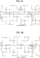
- a differential scanning calorimeter (for example, DSC-60A, manufactured by Shimadzu Corporation) is used to measure the melting starting temperature (Tmfl) of the endothermic peak when the resin powder is heated to the temperature 30 degrees C higher than the melting point thereof for the first time at a temperature rising speed of 10 degrees C per minute. Thereafter, the resin powder is cooled down to -30 degrees C or lower at a temperature falling speed of 10 degrees C per minute (Cycle 1, FIG.
- the melting starting temperature of the endothermic peak represents a temperature at a point -15 mW lower from a straight line parallel to X axis drawn from a site where quantity of heat becomes constant after endotherm at the melting point finishes to the lower temperature side. As illustrated in FIGS.
- the melting starting temperature of the endothermic peak is a temperature (Tmf) corresponding to the intersection of the endothermic peak and -15 mW lower from a straight line parallel to X axis (temperature axis) drawn from a site where quantity of heat becomes constant after endotherm at the melting point finishes to the lower temperature side.
- the melting starting temperature is the intersection between the straight line of the base line on the low temperature side extended into the high temperature side and a tangent of the curve on the low temperature side of the melting peak at the point where the gradient is the maximum.
- the measuring method of crystallinity of differential scanning calorimetry (DSC) of the condition (2) is based on the measuring method according to ISO 3146 (Testing Methods for Transition Temperatures of Plastics, JIS K7121).
- the energy amount (heat amount of melting) of an endothermic peak when heated to the temperature 30 degrees C higher than the melting point of powder resin is measured to obtain crystallinity (Cd1) from the heat amount of melting to the heat amount of perfect crystallization.
- the resin powder is cooled down to -30 degrees C or lower at a temperature falling speed of 10 degrees C per minute and heated to the temperature 30 degrees C higher than the melting point at a temperature rising speed of 10 degrees C per minute to measure the energy amount of the endothermic peak so that crystallinity (Cd2) can be obtained from the heat amount of melting to the heat amount of perfect crystallization.
- Crystallinity of resin powder of the condition 3 is obtained by, for example, placing the resin powder on glass plate to measure crystallinity (C ⁇ 1) thereof by an X-ray analyzer including a two-dimensional detector (for example, Discover 8, manufactured by Bruker) at a 2 ⁇ range of from 10 to 40 at room temperature. Next, in the DSC, in a nitrogen atmosphere, the resin is heated to 30 degrees C higher than the melting point thereof at a temperature rising speed of 10 degrees C per minute.
- Crystallinity (C ⁇ 2) can be measured like C ⁇ 1.
- the melting point means a melting peak temperature measured according to ISO 3146 (Testing Methods for Transition Temperatures of Plastics, JIS K7121).
- ISO 3146 Testing Methods for Transition Temperatures of Plastics, JIS K7121.
- the melting point on the higher temperature side is used.
- crystallinity is controlled, the ratio of fine crystal or non-crystal decreases.
- the starting temperature of the endothermic peak in the DSC shifts to high temperatures. Therefore, the endothermic temperature of a resin becomes clear so that a sharp melt waveform where the resin is melted at laser center portion is obtained.
- Sharp melt generally means that the melting starting temperature of a resin is high and the range between the starting temperature of the melting point and the endotherm ending peak temperature in the DSC is small so that desired melting conditions can be achieved in more controlled state.
- the melting point of the resin powder for solid freeform fabrication has no particular limit and is preferably 100 degrees C or higher, more preferably 150 degrees C or higher, and particularly preferably 200 degrees C or higher.
- the melting point can be measured according to ISO 3146 (Testing Methods for Transition Temperatures of Plastics, JIS K7121) using a differential scanning calorimeter (DSC).
- the 50 percent cumulative volume particle diameter of the resin powder is from 5 to 200 ⁇ m and preferably from 5 to 100 ⁇ m, more preferably from 20 to 70 ⁇ m, and particularly preferably from 20 to 50 ⁇ m in terms of dimension stability.
- the ratio (Mv/Mn) of the volume average particle diameter (Mv) to the number average particle diameter (Mn) of the powder is 2.50 or less, preferably 2.00 or less, more preferably 1.50 or less, and particularly preferably 1.20 or less in terms of improvement of fabrication accuracy and recoating.
- the 50 percent cumulative volume particle diameter and Mv/Mn can be measured by, for example, particle size distribution measuring device (microtrac MT3300 EXII, manufactured by MicrotracBEL Corp).
- the average circularity of the resin powder for solid freeform fabrication is preferably from 0.7 or higher and more preferably from 0.83 or higher in the particle size range of from 0.5 to 200 ⁇ m.
- the average circularity is an index to indicate the degree of circularity and the average circularity of 1 means true circle.
- Circularity of the resin powder for solid freeform fabrication is measured and the arithmetical average value is determined as the average circularity.
- the average circularity can be easily obtained by digitization based on the measuring using a wet process flow type particle size and form analyzer (FPIA-3000, manufactured by Sysmex Corporation).
- FPIA-3000 wet process flow type particle size and form analyzer
- This device takes particle images at high speed in a liquid suspension flowing in a glass cell by a charge-coupled device (CCD) and analyzes individual particle images in real time.
- CCD charge-coupled device
- This device is suitable to obtain the average circularity in the present disclosure.
- the number of measuring counts has no particular limit and is preferably 1,000 or greater and more preferably 3,000 or greater.
- the specific gravity of the resin powder for solid freeform fabrication is preferably 0.8 or more. When the specific gravity is 0.8 or greater, it is preferable because secondary agglomeration of the particles during recoating can be prevented. Conversely, the specific gravity is preferably 3.0 or less to meet light-weight needs as a substitute of metal.
- the specific gravity can be obtained by measuring true specific gravity.
- the true specific gravity is obtained by measuring the density of a sample by measuring the mass thereof from the volume of the sample. The volume is obtained by changing volume and pressure of gas (He gas) at a constant temperature by using a dry-process pycnometer (AccuPyc 1330, manufactured by Shimadzu Corporation) utilizing gas-phase replacement method.
- the form of the resin particle constituting the powder has no particular limit. Preferably, it is a pillar-like form.
- the particle having a pillar-like form has a ratio of the height of the particle to the diameter or the long side of the bottom of the particle of from 0.5 to 5, preferably from 0.7 to 2.0, and more preferably from 0.8 to 1.5.
- the proportion of the particle having a pillar-like form to the resin powder for solid freeform fabrication is preferably 50 percent by mass or greater, more preferably 70 percent by mass or greater, and particularly preferably 90 percent by mass or greater.
- the pillar-like form there is no specific limit to the pillar-like form. It can be suitably selected to suit to a particular application. For example, significantly cylindrical form and cuboid are preferable.
- the pillar-like form particles can be packed without a space so that the tensile strength of an obtained solid freeform fabrication object can be enhanced.
- the pillar-like form preferably has sides facing each other. The sides facing each other may have an incline. However, they are preferable when they are parallel to each other without an incline in terms of productivity and stability of laser fabrication.
- the form of the particle can be observed by, for example, scanning electron microscope (S4200, manufactured by Hitachi Ltd.), wet-process particle size and form analyzer (FPIA-3000, manufactured by Sysmex Corporation), etc. Obtained particles may be subject to spheroidizingcal treatment or addition of external additives to improve powder flowability.
- the significantly cylindrical form there is no specific limit to the significantly cylindrical form. It can be suitably selected to suit to a particular application. For example, true cylindrical form and cylindroid-like form are preferable. Of these, true cylindrical form is preferable.
- the circle portion of the significantly cylindrical form may partially chip.
- the significantly cylindrical (significantly circular) has a ratio of the major axis to the minor axis of from 1 to 10.
- the significantly cylindrical form preferably has significantly circular planes facing each other.
- the size of the circles facing each other may not be completely identical but the diameter ratio of the large circle to the small circle is preferably 1.5 or less. More preferably, the ratio is 1.1 or less, meaning if the size is close to each other, particles can be packed more densely.
- the diameter of the significantly cylindrical form has no particular limit and can be suitably selected to suit to a particular application.
- the diameter is preferably from 5 to 200 ⁇ m.
- the diameter means the major axis.
- the height (distance between both planes) of the significantly cylindrical form has no particular limit and can be suitably selected to suit to a particular application.
- the height is preferably from 5 to 200 ⁇ m.
- the particle has a pillar-like form having a bottom and a top. Of these, forms having no points at ends are more preferable.
- the point means an end portion existing in the pillar-like form.
- FIG. 1B is a side view of the cylindrical form illustrated in FIG. 1A .
- the cylindrical form has a rectangular form with four angle portions, i.e., points.
- FIG. 1C is a diagram illustrating an example of a form without such points. Whether a pillar-like form has a point is confirmed by a projected image of the side plane of the pillar-like form particle.
- the side of a pillar-like form particle is observed by a scanning electron microscope (S4200, manufactured by Hitachi Ltd.), etc. to acquire a two-dimensional image. In this case, the projected image has four sides.
- the portion formed of two adjacent sides is defined as an end part
- the end part is formed of only two adjacent straight lines, an angle is formed and the particle has a point. If the end part is arc as illustrated in FIG. 1C , no point is formed at the end portion.
- Circularity of such a pillar-like form particle having no point can be increased so that flowability is enhanced and packing density can be more increased. This is extremely suitable to improve the strength of a solid freeform fabrication object and dimension accuracy.
- all the pillar-like form particles of the resin powder for solid freeform fabrication have no points at end portions. It is preferable that the proportion of the pillar-like form particles having no point at end portions be high. Specifically, the proportion of the pillar-like form particles having no point at end portions to all the pillar-like form particles is preferably 50 percent or more, more preferably 75 percent or more, and furthermore preferably 90 percent or more. Due to this, the average circularity of the resin powder increases, which is preferable for the present disclosure.
- Whether the pillar-like form particle has no point at end portions can be determined by, for example, as described above, observing the resin powder with a scanning electron microscope (S4200, manufactured by Hitachi Ltd.), etc. to obtain two-dimensional images and calculating the proportion of the pillar-like form particles having no point at end portions to all the pillar-like form particles.
- the two-dimensional images of 10 vision fields are obtained by the method described above to obtain the proportion of the pillar-like form particles having no point at end portions to all the pillar-like form particles and calculate the average.
- the pillar-like form particle having no point at end portions has not necessarily neat significantly cylindrical forms or polygonal forms but may include a form with constriction, a form having an extended end portion, a crushed form, or a twisted or curved form in the projected image of side plane.
- any method of rounding points of pillar-like form particles can be used.
- the cuboid has no specific limit and is suitably selected to suit to a particular application.
- cuboid and cube are usable. Of these, cube is preferable.
- the cuboid may partially chip. In terms of narrowing the degree of dispersion to pack particles more densely, cube having equal side length is preferable.
- the cuboid preferably has square or rectangle planes facing each other.
- each side of the bottom of the cuboid has no particular limit and can be suitably selected to suit to a particular application.
- each side is preferably from 5 to 200 ⁇ m.
- the long side of each side is the longest side when one plane is set to be the bottom of a cuboid.
- the cuboid is cube, it is one of the sides having an equal length of the bottom.
- the height of the cuboid has no particular limit and can be suitably selected to suit to a particular application.
- each side is preferably from 5 to 200 ⁇ m. The height means the direction to the bottom of the cuboid.
- the side forming the height between planes of the pillar-like form includes crushed state (barrel-like form in the case of pillar-like form) in which the resin softens at cutting.
- crushed state barrel-like form in the case of pillar-like form
- the side is preferably straight in terms of more dense packing of powder.
- 50 percent cumulative volume particle diameter is preferably from 5 to 100 ⁇ m.
- collective entity of powder which is formed close to mono-dispersion is more preferable because it has uniform height with no deviation about the form and size.
- the form In the case of the significantly cylindrical form, it is preferable that the form have a diameter more nearly equal to the height in terms of reproducibility.
- cube having equal height and side is preferable in the case of cuboid.
- the resin powder for solid freeform fabrication is preferably constituted of only particles but it is suitable to mix with pulverized material.
- the proportion of particle is preferably from 50 to 100 percent by mass, more preferably from 80 to 100 percent by mass, and furthermore preferably from 90 to 100 percent by mass to the total content of the resin powder for solid freeform fabrication. When the proportion is 50 to 100 percent by mass, it is possible to pack the particles more densely.
- a large temperature difference (temperature window) about crystal layer change is preferable to prevent warping. It is preferable that the crystal layer change be larger because resin powder having a large difference between the melting starting temperature and the recrystallization point during cooling has better fabrication property. When multiple melting temperatures exist, the starting temperature on the lower temperature side is used.
- the crystalline thermoplastic resin include, but are not limited to, polymers such as polyolefin, polyamide, polyester, polyarylketone, polyphenylene sulfide, a liquid crystal polymer (LCP), polyacetal (POM, melting point: 175 degrees C), polyimide, and a fluorochemical resin. These can be used alone or in combination.
- the crystalline thermoplastic resin may include additives such as flame retardants, plasticizers, heat stabilizing agents, and crystal nucleating agents and polymer particles such as non-crystalline resins other than the polymers mentioned above. These can be used alone or in combination.
- the polymer particles can be mixed. Also, it is also possible to coat the surface of the polymer particle with the polymer particle.
- polystyrene resin examples include, but are not limited to, are polyethylene and polypropylene (PP, melting point: 180 degrees C). These can be used alone or in combination.
- polyamide 410 PA410
- PA6 polyamide 6
- PA66 polyamide 66
- PA11 polyamide 612
- PA12 polyamide 11
- PA11 polyamide 12
- PA12 semi-aromatic polyamide 4T
- PA4T polyamide MXD6
- PA6T polyamide 6T
- PA9T melting point: 300 degrees C
- PA10T polyamide 10T
- PA9T is also referred to as polynonamethylene terephthal amide constituted of a diamine having 9 carbon atoms and a terephthalic acid monomer.
- carbon acid side is an aromatic series
- PA9T is referred to as semi-aromatic series.
- aramid constituted of p-phenylenediamine and a terephathalic acid monomer as aromatic series in which diamine side is also aromatic is included as the polyamide in the present disclosure.
- polyester examples include, but are not limited to, polyethyleneterephthalate (PET), polybutadiene terephthalate (PBT, melting point: 218 degrees C), and polylactic acid (PLA).
- PET polyethyleneterephthalate
- PBT polybutadiene terephthalate
- PLA polylactic acid
- polyester partially including aromatic series including terephthalic acid and isophthalic acid is also suitably used in the present disclosure.
- polyarylketone examples include, but are not limited to, polyether etherketone (PEEK, melting point: 343 degrees C), polyetherketone (PEK), polyether ketone ketone (PEKK), polyaryl ether ketone (PAEK), polyether ether ketone ketone (PEEKK), and polyetherkeone ether ketone ketone (PEKEKK).
- PEEK polyether etherketone
- PEKK polyether ketone ketone
- PAEK polyaryl ether ketone
- PEEKK polyether ether ketone ketone
- PEKEKK polyetherkeone ether ketone ketone
- crystalline polymers are also suitable.
- polyacetal polyacetal
- polyimide polyimide
- polyether sulfone polyamide having two melting peaks
- PA9T it is necessary to raise the temperature of a resin to the second melting peak or higher to completely melt the resin.
- the resin powder for solid freeform fabrication may furthermore optionally include, flowability increasing agent (fluidizer), toughening agent, antioxidant, and flame retardant.
- the fluidizer partially or entirely covers the surface of the resin powder for solid freeform fabrication to improve flowability of the resin powder for solid freeform fabrication. If flowability of the resin powder for solid freeform fabrication increases, surface smoothness of the powder layer during recoating increases, In addition, voids in the resin powder for solid freeform fabrication are reduced, which makes it possible to further improve surface property, dimension accuracy, and strength of a solid freeform fabrication object. It is preferable that such fluidizer cover the surface of the resin powder. Some of them may be contained in the resin powder for solid freeform fabrication.
- the average primary particle diameter of the fluidizer is preferably 500 nm or less and more preferably 50 nm or less.
- the covering ratio of surface of the resin powder for solid freeform fabrication by fluidizer can be increased. Also, flowability is improved and voids can be reduced.
- the average primary particle diameter can be measured by, for example, a particle size measuring system (ELSZ-2000ZS, manufactured by OTSUKA ELECTRONICS Co., LTD.).
- the fluidizer there is no specific limit to the fluidizer and it can be suitably selected to suit to a particular application.
- spherical inorganic particles are preferable.
- metal oxide is preferable.
- Specific examples include, but are not limited to, silica, alumina, titania, magnesium oxide, tin oxide, iron oxide, and copper oxide. These can be used alone or in combination.
- silica and titania are preferable.
- the fluidizer having a hydrophobized surface is preferably used.
- hydrophobizing method there is no specific limit to the hydrophobizing method and known methods can be suitably selected.
- silane coupling agents such as hexamethyl disilazane (HMDS) and dimethyldichlorosilane (DMDS)
- silicone oil treating agent such as dimethyl silicone oil and amino-modified silicone oil.
- siliane coupling agent are preferably used.
- the processing amount of the hydrophobizing agent is preferably from 2 to 6 mg/m 2 for the surface area of particle.
- Known powder mixers are used in the mixing and coating processes of the fluidizer with the resin powder for solid freeform fabrication.
- Mixers equipped with a jacket, etc. is preferably used to control the temperature of the inside.
- mixers include, but are not limited to, V-type mixers, Henschel Mixer, Rocking mixers, Nautor mixers, and Super mixers.
- the proportion of the fluidizer is suitable when sufficient to cover the surface of particles and it is preferably from 0.05 to 10 percent by mass, more preferably from 0.05 to 3 percent by mass, and particularly preferably from 0.1 to 1.5 percent by mass to the total content of the resin powder for solid freeform fabrication.
- proportion is from 0.05 to 10 percent by mass, flowability of the resin powder for solid freeform fabrication can be improved and at the same time the impact of reduction of filling density ascribable to an increase of voids can be minimized.
- Particulate inorganic material having a volume average particle diameter of less than 10 ⁇ can be the fluidizer.
- fluidizder examples include, but are not limited to, alumina, talc, glass-like silica, titania, hydrated silica, silica having a surface modified with a silane-coupling agent, and magnesium silicate.
- the antioxidant in terms of preventing deterioration of the resin, it is preferable to add the antioxidant thereto.
- the antioxidant are hydrazine-based agents metal chelate, triadine based agents as ultraviolet absorber, hindered phenol-based agents as radical supplement agent, and phosphate-based and sulfur-containing agent as antioxidant. These can be used alone or in combination.
- Fiber fillers, bead fillers, and articles disclosed in WTO 2008/057844 are suitable to improve the strength. These can be used alone or in combination.
- the resin powder for solid freeform fabrication of the present disclosure is preferably dried suitably. Using a vacuum drier or silica gel is suitable to dry the resin powder before usage.
- fiber filler there is no specific limit to fiber filler and it can be suitably selected to suit to a particular application.
- fiber filler For example, carbon fiber, inorganic glass fiber, and metal fiber are preferable.
- bead filler there is no specific limit to bead filler and it can be suitably selected to suit to a particular application.
- carbon bead, inorganic glass fiber, and metal bead are preferable.
- powder mixture of the resin powder for solid freeform fabrication of the present disclosure (which is the crystalline thermoplastic resin composition having sharp melting property), fiber filler, and bead filler are not easily melted even when the resin temperature outside laser irradiation rises due to heat diffusion because the resin powder has sharp melting property. Therefore, excessive fabrication can be prevented and high fabrication accuracy can be maintained.
- the fiber filler preferably has an average fiber diameter of from 1 to 30 ⁇ m and an average fiber length of from 30 to 500 ⁇ m.
- the bead filler preferably has a circularity of from 0.8 to 1.0 and a volume average particle diameter of from 10 to 200 ⁇ m.
- the volume average particle diameter can be measured by using a particle size distribution measuring instrument (Microtrac MT3300EXII, manufactured by MicrotracBEL Corp.).
- the proportion of the fiber filler is preferably from 5 to 60 percent by mass to the total content of the resin powder for solid freeform fabrication. When the proportion is below this range, strength is not enhanced by this addition of fiber filler. When the proportion is above this range, fabrication becomes difficult.
- the proportion of the bead filler is preferably from 5 to 60 percent by mass to the total content of the resin powder for solid freeform fabrication.
- halogen-based, phosphorus-based, inorganic hydrated metal compound-based, nitrogen-containing, silicone-containing retardants examples are halogen-based, phosphorus-based, inorganic hydrated metal compound-based, nitrogen-containing, silicone-containing retardants. These can be used alone or in combination. If two or more flame retardants are used in combination, the combination of halogen-based and inorganic hydrated metal compound-based retardants is preferable to improve flame retardancy.
- Flame retardancy can be enhanced by adding inorganic toughening agents such as inorganic fibrous materials such as glass fiber, carbon fiber, aramid fiber and inorganic laminate silicate such as talc, mica, and montmorillonite. Inclusion of such material makes it possible to meet a balance between enhancing property and flame retardancy.
- inorganic toughening agents such as inorganic fibrous materials such as glass fiber, carbon fiber, aramid fiber and inorganic laminate silicate such as talc, mica, and montmorillonite. Inclusion of such material makes it possible to meet a balance between enhancing property and flame retardancy.
- Flame retardancy of the resin powder for the solid freeform fabrication can be evaluated by, for example, JIS K6911, JIS L1091 (ISO 6925), JIS C3005, and pyrogen test (using a cone calorimeter).
- the proportion of the flame retardant is preferably from 1 to 50 percent by mass and more preferably from 10 to 30 percent by mass to the total content of the resin powder for solid freeform fabrication.
- the proportion is 1 percent by mass or more, flame retardancy is sufficiently secured.
- the proportion is 50 percent by mass or less, melt-solidification property of the resin powder for solid freeform fabrication does not change easily and it is possible to prevent deterioration of fabrication accuracy and properties.
- the resin powder for solid freeform fabrication can be used in the SLS method or SMS method and has properties striking a balance between parameters such as particle size, particle size distribution, heat transfer properties, melt viscosity, bulk density, flowability, melting temperature, and recrystallization temperature.
- the bulk density of the resin powder for solid freeform fabrication is preferably large.
- it is preferably 0.30 g/mL or greater, more preferably 0.35 g/mL or greater, and particularly preferably 0.40 g/mL or greater.
- a fabricated object formed by laser sintering using the resin powder for solid freeform fabrication is smooth and has a surface having a resolution sufficient to indicate minimum orange peel or less.
- the orange peel means surface deficiency such as unsuitable coarse surface or voids or warping on the surface of a fabricated object formed by laser sintering in the PBF method in general.
- the void has a significant impact on aesthetic appearance and mechanical strength.
- solid freeform fabrication objects formed by laser sintering using the resin powder for solid freeform fabrication be free of unsuitable process properties such as warping and distortion due to phase changes and fuming during sintering until cooling after sintering.
- the resin powder for solid freeform fabrication of the present disclosure has excellent recyclability. Also, solid freeform fabrication objects formed of fresh powder by the PBF method are free of (a) orange peel and (b) significant deterioration in mechanical performance (10 percent or more deterioration in tensile strength).
- a dog-bone-like test specimen for multiple purposes having a length of 150 mm free of (a) and (b) mentioned above can be manufactured by a manufacturing device employing PBF method (AM S5500P, manufactured by Ricoh Company Ltd.).
- the resin powder for solid freeform fabrication can be obtained by typical pulverization method.
- the powder is obtained by pulverizing pellets, etc. at room temperature using a pulverizer.
- the obtained powder is subject to classification using a filter to remove particles having a diameter outside the target. It is preferable that the powder be obtained by pulverization at low temperatures of 0 degrees C or below (not higher than the brittleness temperature of each resin), more preferably -25 degrees C or below, and particularly preferably at extremely low temperatures of -100 degrees C or below utilizing resin brittleness.
- the resin powder for solid freeform fabrication can also be obtained by extending pellets, etc. several times to obtain fiber having a size of several tens ⁇ m to several hundreds ⁇ m and cutting the fiber with laser cutting or blades so that the fiber has a size of several ⁇ m to several hundreds ⁇ m. Both methods can be used in combination.
- Melted resin for solid freeform fabrication is extruded in fibrous form by an extruder during stirring at temperatures 30 degrees C or greater higher than the melting point.
- the melted resin for solid freeform fabrication is extended to around 1/1 to around 1/10 (ten times) to obtain fiber.
- the form of the cross section of the fiber can be determined by the form of the nozzle mouth of the extruder.
- the nozzle mouth is preferably circular.
- the nozzle mouth is preferably a cuboid or square form.
- Productivity increases in proportion to the number of nozzles. The maximum extension ratio can be changed depending on resin and melt viscosity.
- the resin powder can be spheroidized by a solvent to dissolve the resin powder or a spherical stirrer while heat is applied.
- the powder layer portion is selectively melted.
- the new powder layer is formed on the previously formed layer and selectively melted again. This operation is repeated until a target solid freeform fabrication object is manufactured.
- the resin powder for solid freeform fabrication is typically melted by electromagnetic wave irradiation.
- the resin powder is selectively melted by, for example, retardants, absorbents, or electromagnetic wave irradiation (for example, by masking or direct laser beams).
- electromagnetic wave irradiation sources There is no specific limit to selections of electromagnetic wave irradiation sources.
- CO 2 laser, infra red irradiation source, microwave generators, radiant heaters, LED lamps, and combinations thereof are usable.
- solid freeform fabrication objects of the present disclosure can be manufactured using selective mask sintering (SMS) technologies.
- SMS selective mask sintering
- powder layers are partially and selectively irradiated with infra red while being selectively shielded by using a shielding mask.
- a shielding mask When utilizing the SMS process to manufacture an article from the resin powder for solid freeform fabrication of the present disclosure, it is preferable to contain at least one kind of material to enhance infrared absorption of the resin powder for solid freeform fabrication.
- the resin powder for solid freeform fabrication may contain at least one kind of heat absorbent and/or dark color material (such as carbon fiber, carbon black, carbon nanotube, and cellulose nanofiber).
- the sintered layer preferably has a thickness suitable for the fabrication process.
- the average thickness of the multiple sintered layers is preferably 10 ⁇ m or greater, more preferably 50 ⁇ m or greater, and particularly preferably 100 ⁇ m or greater.
- the average thickness of the multiple sintered layers is preferably less than 200 ⁇ m, more preferably less than 150 ⁇ m, and particularly preferably less than 120 ⁇ m.
- the resin powder for solid freeform fabrication of the present disclosure can be suitably used to form articles used as prototypes of electronic device parts, vehicle parts, and prototypes for strength test, and low volume products for use in aerospace or dress up tools for the auto industry.
- Methods other than the PBF method are expected to manufacture objects having excellent strength in comparison with FDM and inkjet, so that objects manufactured by such methods can be practically used.
- the production speed is not on par with mass production of injection molding, etc. However, for example, it is possible to obtain required amount of production by manufacturing a massive amount of small parts in a two-dimensional manner.
- the method of manufacturing a solid freeform fabrication object by PBF method for use in the present disclosure obviates the need for dies unlike injection molding. Therefore, overwhelming cost reduction and short delivery time are achieved in the case of manufacturing prototypes if utilizing this method.
- the method of manufacturing a solid freeform fabrication object of the present disclosure includes forming a layer containing the resin powder for solid freeform fabrication of the present disclosure, applying electromagnetic wave to the formed layer to melt it, cooling down the melted layer to cure it, and repeating the film forming, applying, and cooling down.
- the method may furthermore optionally include other processes.
- the device for manufacturing a solid freeform fabrication object includes a layer forming device to form a layer including the resin powder for solid freeform fabrication object of the present disclosure and a powder attaching device to attach resin powder to each other in a selected area of the layer and may furthermore optionally include other devices.
- the method of manufacturing a solid freeform fabrication object of the present disclosure can be suitably executed by the device for manufacturing a solid freeform fabrication object.
- An example of the powder attaching device is a curing device that irradiates levelized powder with electromagnetic wave or laser beams to melt and cool down the resin powder for curing.
- electromagnetic wave generator for use in electromagnetic wave irradiation are CO 2 laser, infra red irradiation source, microwave generators, radiant heaters, LED lamps, and combinations thereof are usable.
- the device for manufacturing a solid freeform fabrication object is described referring to FIG. 2 .
- FIG. 2 is a schematic diagram illustrating an example of the device for manufacturing a solid freeform fabrication object for use in the method of manufacturing a solid freeform fabrication object of the present disclosure.
- powder is stored in a supplying tank 5 for powder and supplied to a laser scanning space 6 using a roller 4 in proportion to the usage amount. It is preferable that the temperature of the supplying tank 5 be controlled by a heater 3.
- the laser scanning space 6 is irradiated with the laser beams emitted from an electromagnetic wave irradiation source 1 using a reflection mirror 2.
- the powder is sintered by the heat of the laser beams to obtain a solid freeform fabrication object.
- the temperature of the supplying tank 5 is preferably at least 10 degrees C or more lower than the melting point of the powder.
- the temperature of the part bed in the laser scanning space 6 is preferably 5 degrees C or more lower than the melting point of the powder.
- the power of the laser has no particular limit and can be suitably selected to suit to a particular application. For example, it is preferably from 10 to 150 W.
- the solid freeform fabrication object can be suitably manufactured by the method of manufacturing a solid freeform fabrication object of the present disclosure.
- the 50 percent cumulative volume particle diameter, the volume average particle diameter, and the number average particle diameter were measured by using a particle size distribution measuring instrument (Microtrac MT3300EXII, manufactured by MicrotracBEL Corp.) employing a drying process (atmosphere) method without using a solvent, utilizing particle refractive index per resin powder.
- the particle refractive index was set for polybutylene terephthalate (PBT) resin of 1.57, polyamide 66 (PA66) resin of 1.53, polyamide 9T (PA9T) resin of 1.53, polypropylene (PP) resin of 1.48, polyether ether ketone (PEEK) resin of 1.57, and polyacetal (POM) resin of 1.48.
- PBT polybutylene terephthalate
- PA66 polyamide 66
- PA9T polyamide 9T
- PP polypropylene
- PEEK polyether ether ketone
- POM polyacetal
- the average circularity was measured by a wet-process flow type particle size/form analyzer (FPIA-3000, manufactured by SYSMEX CORPORATION).
- the melting point can be measured according to ISO 3146 (Testing Methods for Transition Temperatures of Plastics, JIS K7121) using a differential scanning calorimetry (DSC).
- a differential scanning calorimeter (DSC-60A, manufactured by Shimadzu Corporation) was used to measure the melting starting temperature (Tmfl) of the endothermic peak as the resin powder was heated to the temperature 30 degrees C higher than the melting point thereof for the first time at a temperature rising speed of 10 degrees C per minute. Thereafter, the resin powder was cooled down to -30 degrees C or lower at a temperature falling speed of 10 degrees C per minute and heated to the temperature 30 degrees C higher than the melting point for the second time at a temperature rising speed of 10 degrees C per minute to measure the melting starting temperature (Tmf2) of the endothermic peak.
- the melting starting temperature of the endothermic peak represents a temperature at a point -15 mW lower from a straight line parallel to X axis drawn from a site where quantity of heat becomes constant after endotherm at the melting point is finished to the lower temperature side.
- the measuring method of crystallinity of the condition (2) of differential scanning calorimetry (DSC) is based on the measuring method according to ISO 3146 (Testing Methods for Transition Temperatures of Plastics, JIS K7121).
- the energy amount (heat amount of melting) of an endothermic peak when heated to the temperature 30 degrees C higher than the melting point of powder resin at a temperature rising speed of 10 degrees C per minute was measured to obtain crystallinity (Cd1) from the heat amount of melting to the heat amount of perfect crystallization.
- the resin powder is cooled down to -30 degrees C or lower at a temperature falling speed of 10 degrees C per minute and heated to the temperature 30 degrees C higher than the melting point at a temperature rising speed of 10 degrees C per minute to measure the energy amount of the endothermic peak so that crystallinity (Cd2) can be obtained from the heat amount of melting to the heat amount of perfect crystallization.
- Crystallinity of resin powder of the condition 3 was obtained by measuring crystallinity (C ⁇ 1) of the resin powder placed on a glass plate by an X-ray analyzer including a two-dimensional detector (Discover 8, manufactured by Bruker) at a 2 ⁇ range of from 10 to 40 at room temperature. Next, in the DSC, in a nitrogen atmosphere, the resin was heated to 30 degrees C higher than the melting point thereof at a temperature rising speed of 10 degrees C per minute. The temperature was kept for 10 minutes, cooled down to -30 degrees C at a temperature falling speed of 10 degrees C per minute, and thereafter the temperature of the sample (resin powder) was returned to room temperature. Crystallinity (C ⁇ 2) was measured in the same manner as with C ⁇ 1.
- the thus-obtained powder was pulverized until the size ranged from 5 to 100 ⁇ m.
- the 50 percent cumulative volume particle diameter was from 20 to 90 ⁇ m.
- the obtained powder was subject to annealing under the following condition to obtain controlled crystalline thermoplastic resin powder.
- the thus-obtained powder was heated at the temperature 50 degrees higher than the glass transition temperature thereof for three days to increase crystallinity and thereafter slowly cooled down to room temperature. Sampling was conducted in the middle to check crystallinity,
- Thermoplastic resin powder was obtained in the same manner as in Example 1 except that annealing for crystallization was not conducted.
- Controlled thermoplastic resin powder was obtained in the same manner as in Example 1 except that annealing for crystallization was changed to the extension under the following condition.
- Obtained powder was stirred at the temperature 30 degrees C higher than the melting point by an extruder and thereafter extruded and extended to obtain a melted resin for solid freeform fabrication in a fibrous resin. Each of the resin was extended to 1.5 to 10 times to obtain the fibrous resin and thereafter directly cut to 0.07 mm or less.
- Controlled thermoplastic resin powder was obtained in the same manner as in Example 1 except that annealing for crystallization was changed to the ultrasonic wave under the following condition.
- Glycerin (reagent grade, manufactured by Tokyo Chemical Industry Co. Ltd.) solvent was added to resin powder in an amount of five times as much as the resin followed by heating to the temperature 20 degrees C higher than the melting point. Thereafter, ultrasonic wave was applied thereto by an ultrasonic wave generator (ultrasonicator UP200S, manufactured by Hielscher Ultrasonics GmbH) at a frequency of 24 KHz and an amplitude of 60 percent for two hours. Thereafter, the resultant was rinsed with a solvent of isopropanol at room temperature and subject to vacuum drying.
- ultrasonic wave generator ultrasonicator UP200S, manufactured by Hielscher Ultrasonics GmbH
- Thermoplastic resin powder was obtained in the same manner as in Example 2 except that fiber was obtained without the extension treatment and directly cut 0.07 mm or less.
- Thermoplastic resin powder was obtained in the same manner as in Example 2 except that the extension ratio of the fiber was changed to 1.05 times.
- Controlled crystalline thermoplastic resin powder was obtained in the same manner as in Example 2 except that polybutylene terephthalate (PBT) resin was changed to polyamide 66 (PA66) resin (Leona TM 1300S, melting point: 265 degrees C, manufactured by Asahi Kasei Chemicals Corporation).
- PBT polybutylene terephthalate
- PA66 polyamide 66
- Thermoplastic resin powder was obtained in the same manner as in Example 4 except that extension for crystallization was not conducted.
- Controlled crystalline thermoplastic resin powder was obtained in the same manner as in Example 2 except that polybutylene terephthalate (PBT) resin was changed to polyamide 9T (PA9T) resin (Genestar TM N1000A, melting point: 300 degrees C, manufactured by KURARAY CO., LTD.).
- PBT polybutylene terephthalate
- PA9T polyamide 9T
- Thermoplastic resin powder was obtained in the same manner as in Example 5 except that extension for crystallization was not conducted.
- Controlled crystalline thermoplastic resin powder was obtained in the same manner as in Example 1 except that polybutylene terephthalate (PBT) resin was changed to polypropylene (PP) resin (NOVATEC TM MA3, melting point: 180 degrees C, glass transition temperature: 0 degrees C, manufactured by JAPAN POLYPROPYLENE CORPORATION).
- PBT polybutylene terephthalate
- PP polypropylene
- Thermoplastic resin powder was obtained in the same manner as in Example 6 except that annealing for crystallization was not conducted.
- Controlled crystalline thermoplastic resin powder was obtained in the same manner as in Example 1 except that polybutylene terephthalate (PBT) resin was changed to polyetherether ketone (PEEK) resin (HT P22PF, melting point: 343 degrees C, glass transition temperature: 143 degrees C, manufactured by VICTREX).
- PBT polybutylene terephthalate
- PEEK polyetherether ketone
- Thermoplastic resin powder was obtained in the same manner as in Example 7 except that annealing for crystallization was not conducted.
- Controlled crystalline thermoplastic resin powder was obtained in the same manner as in Example 3 except that polybutylene terephthalate (PBT) resin was changed to polyacetal (POM) resin (Jupital ® F10-01, melting point: 175 degrees C, manufactured by Mitsubishi Engineering-Plastics Corporation).
- PBT polybutylene terephthalate
- POM polyacetal
- Thermoplastic resin powder was obtained in the same manner as in Example 8 except that application of ultrasonic wave for crystallization was not conducted.
- a solid freeform fabrication object was manufactured by an SLS method fabrication device (AM S5500P, manufactured by Ricoh Company, Ltd.) using the obtained resin powder (resin powder for solid freeform fabrication).
- the conditions were: average layer thickness of 0.1 mm, a laser output of from 10 to 150 W, a laser scanning space of 0.1 mm, and a part bed temperature of 3 degrees C above or below the melting point.
- the temperature of the supplying tank was set to 10 degrees C below the melting point.
- the difference between the CAD data of the sample for dimension and the length of each side of the fabricated (manufactured) sample was obtained.
- the average of the differences was defined as dimensional error to evaluate accuracy.
- a multi-purpose dog-bone-like test specimen (specimen having a center portion of a length of 80 mm, a thickness of 4 mm, and a width of 10 mm) having a length of 150 mm of ISO 3167 Type 1A was used.
- the powder used for fabrication was returned to the supplying bed, used for the fabrication as described above, and returned to the supplying bed. This fabrication operation was repeated 10 times.
- the thus-obtained solid freeform fabrication object was subject to the tensile test according to ISO 527 by a tensile tester (AGS-5kN, manufactured by Shimadzu Corporation) to evaluate relyclability based on the following evaluation criteria.
- the test speed in the tensile test was constant at 50 mm/minute.
- the maximum stress was determined as the tensile strength.
- the solid freeform fabrication object for the first time was subject to the test five times.
- the initial value of mechanical strength is the average of the obtained five measuring values.
- the thus-obtained solid freeform fabrication object was subject to the tension test according to ISO 527 by a tension tester (AGS-5kN, manufactured by Shimadzu Corporation) to measure the initial tensile strength of the obtained solid freeform fabrication object.
- the test speed in the tensile test was constant at 50 mm/minute.
- the solid freeform fabrication object for the first time was subject to the test five times.
- the initial value of tensile strength is the average of the obtained five measuring values.
- Example 2 flame retardant was added in Example 2 or 4 as described in Examples 9 to 17 to obtain resin powder for solid freeform fabrication.
- the results are shown in Table 3.
- Examples 2 and 4 are shown in Table 3 for comparison.
- Controlled crystalline thermoplastic resin powder was obtained in the same manner as in Example 2 except that halogen (bromine)-based flame retardant ("NONNEN"PR-2H, manufactured by Marubishi Oil Chemical Corporation) was added in an amount of 30 percent by mass when the PBT resin was charged in the extruder.
- halogen (bromine)-based flame retardant (“NONNEN”PR-2H, manufactured by Marubishi Oil Chemical Corporation) was added in an amount of 30 percent by mass when the PBT resin was charged in the extruder.
- Controlled crystalline thermoplastic resin powder was obtained in the same manner as in Example 2 except that phosphorus-based flame retardant ("NONNEN”75, manufactured by Marubishi Oil Chemical Corporation) was added in an amount of 30 percent by mass when the PBT resin was loaded in the extruder.
- phosphorus-based flame retardant (“NONNEN”75, manufactured by Marubishi Oil Chemical Corporation) was added in an amount of 30 percent by mass when the PBT resin was loaded in the extruder.
- Controlled crystalline thermoplastic resin powder was obtained in the same manner as in Example 2 except that halogen (bromine)-based flame retardant ("NONNEN"PR-2H, manufactured by Marubishi Oil Chemical Corporation) was added in an amount of 10 percent by mass when the PBT resin was loaded in the extruder.
- halogen (bromine)-based flame retardant (“NONNEN”PR-2H, manufactured by Marubishi Oil Chemical Corporation) was added in an amount of 10 percent by mass when the PBT resin was loaded in the extruder.
- Controlled crystalline thermoplastic resin powder was obtained in the same manner as in Example 2 except that halogen (bromine)-based flame retardant ("NONNEN"PR-2H, manufactured by Marubishi Oil Chemical Corporation) was added in an amount of 0.9 percent by mass when the PBT resin was loaded in the extruder.
- halogen (bromine)-based flame retardant (“NONNEN”PR-2H, manufactured by Marubishi Oil Chemical Corporation) was added in an amount of 0.9 percent by mass when the PBT resin was loaded in the extruder.
- Controlled crystalline thermoplastic resin powder was obtained in the same manner as in Example 2 except that halogen (bromine)-based flame retardant ("NONNEN"PR-2H, manufactured by Marubishi Oil Chemical Corporation) was added in an amount of 50 percent by mass when the PBT resin was loaded in the extruder.
- halogen (bromine)-based flame retardant (“NONNEN”PR-2H, manufactured by Marubishi Oil Chemical Corporation) was added in an amount of 50 percent by mass when the PBT resin was loaded in the extruder.
- Controlled crystalline thermoplastic resin powder was obtained in the same manner as in Example 2 except that inorganic hydrated metal compound-based (anthimony trioxide) flame retardant (PATOX-L, manufactured by Nihon Seiko Co., LTD.) was added in an amount of 30 percent by mass when the PBT resin was loaded in the extruder.
- inorganic hydrated metal compound-based (anthimony trioxide) flame retardant PATOX-L, manufactured by Nihon Seiko Co., LTD.
- Controlled crystalline thermoplastic resin powder was obtained in the same manner as in Example 2 except that halogen (bromine)-based flame retardant ("NONNEN”PR-2H, manufactured by Marubishi Oil Chemical Corporation) in an amount of 10 percent by mass and inorganic hydrated metal compound-based (antimony trioxide) flame retardant (PATOX-L, manufactured by Nihon Seiko Co., LTD.) in an amount of 10 percent by mass were added when the PBT resin was loaded in the extruder.
- halogen (bromine)-based flame retardant (“NONNEN”PR-2H, manufactured by Marubishi Oil Chemical Corporation) in an amount of 10 percent by mass
- PATOX-L inorganic hydrated metal compound-based (antimony trioxide) flame retardant
- Controlled crystalline thermoplastic resin powder was obtained in the same manner as in Example 4 except that halogen (bromine)-based flame retardant ("NONNEN"PR-2H, manufactured by Marubishi Oil Chemical Corporation) was added in an amount of 30 percent by mass when the PA66 resin was loaded in the extruder.
- halogen (bromine)-based flame retardant (“NONNEN”PR-2H, manufactured by Marubishi Oil Chemical Corporation) was added in an amount of 30 percent by mass when the PA66 resin was loaded in the extruder.
- Controlled crystalline thermoplastic resin powder was obtained in the same manner as in Example 4 except that halogen (bromine)-based flame retardant ("NONNEN”PR-2H, manufactured by Marubishi Oil Chemical Corporation) in an amount of 10 percent by mass and inorganic hydrated metal compound-based (antimony trioxide) flame retardant (PATOX-L, manufactured by Nihon Seiko Co., LTD.) in an amount of 10 percent by mass were added when the PA66 resin was loaded in the extruder.
- halogen (bromine)-based flame retardant (“NONNEN”PR-2H, manufactured by Marubishi Oil Chemical Corporation) in an amount of 10 percent by mass
- PATOX-L inorganic hydrated metal compound-based (antimony trioxide) flame retardant
- Example 9 to 17 The values of the conditions 1 to 3 in Examples 9 to 17 are the same as the values of Example 2 or 4 as the resin powder for solid freeform fabrication. In addition, the evaluation results of recyclability, accuracy, and initial tensile strength are the same as those of Example 2 or 4.
- Carbon fiber (TORAYCA ® milled fiber, manufactured by Toray Industries, Inc.) was added in an amount of 60 percent by mass as a filler to the PBT resin powder treated with annealing manufactured in Example 1. The mixture was mixed in dry process for 30 minutes by a screw mixer (mixing stirrer DM type, manufactured by DALTON CORPORATION) to obtain resin powder for solid freeform fabrication. The carbon fiber added had an average fiber diameter of 7 ⁇ m and an average fiber length of 130 ⁇ m.
- Aluminum fiber (melted spinning aluminum fiber, manufactured by AKAO Aluminum Corp.) was added in an amount of 30 percent by mass as a toughening agent (filler) to the PBT resin powder treated with extension manufactured in Example 2.
- the mixture was mixed in dry process for 30 minutes by a screw mixer (mixing stirrer DM type, manufactured by DALTON CORPORATION) to obtain resin powder for solid freeform fabrication.
- the fiber added had an average fiber diameter of 7 ⁇ m and an average fiber length of 130 ⁇ m.
- Glass fiber (Milled Fiber, manufactured by Nippon Electric Glass Co., Ltd.) was added in an amount of 5 percent by mass as a filler to the PBT resin powder treated with ultrasonic wave manufactured in Example 3.
- the mixture was mixed in dry process for 30 minutes by a screw mixer (mixing stirrer DM type, manufactured by DALTON CORPORATION) to obtain resin powder for solid freeform fabrication.
- the fiber added had an average fiber diameter of 18 ⁇ m and an average fiber length of 150 ⁇ m.
- Carbon fiber (TORAYCA ® milled fiber, manufactured by Toray Industries, Inc.) was added in an amount of 70 percent by mass as a filler to the PBT resin powder manufactured in Comparative Example 1.
- the mixture was mixed in dry process for 30 minutes by a screw mixer (mixing stirrer DM type, manufactured by DALTON CORPORATION) to obtain resin powder for solid freeform fabrication.
- the fiber added had an average fiber diameter of 7 ⁇ m and an average fiber length of 130 ⁇ m.
- Carbon fiber (TORAYCA ® milled fiber, manufactured by Toray Industries, Inc.) was added in an amount of 30 percent by mass as a filler to the PBT resin powder manufactured in Comparative Example 1. The mixture was mixed in dry process for 30 minutes by a screw mixer (mixing stirrer DM type, manufactured by DALTON CORPORATION) to obtain resin powder for solid freeform fabrication. The carbon fiber added had an average fiber diameter of 18 ⁇ m and an average fiber length of 400 ⁇ m.
- Carbon bead (NICABEADS ® , manufactured by Nippon Carbon Co., Ltd.) was added in an amount of 60 percent by mass as a filler to the PBT resin powder treated with annealing manufactured in Example 1.
- the mixture was mixed in dry process for 30 minutes by a screw mixer (mixing stirrer DM type, manufactured by DALTON CORPORATION) to obtain resin powder for solid freeform fabrication.
- the added glass bead had a volume average particle diameter of 20 ⁇ m.
- Aluminum bead (atomized aluminum powder #245, manufactured by MINALCO LTD.) was added in an amount of 30 percent by mass as a filler to the PBT resin powder treated with extension manufactured in Example 2. The mixture was mixed in dry process for 30 minutes by a screw mixer (mixing stirrer DM type, manufactured by DALTON CORPORATION) to obtain resin powder for solid freeform fabrication.
- the added glass bead had a volume average particle diameter of 125 ⁇ m.
- Glass bead (A glass bead for filler, GB301S, manufactured by Potters-Ballotini Co., Ltd.) was added in an amount of 20 percent by mass as a filler to the PBT resin powder treated with ultrasonic wave manufactured in Example 3. The mixture was mixed in dry process for 30 minutes by a screw mixer (mixing stirrer DM type, manufactured by DALTON CORPORATION) to obtain resin powder for solid freeform fabrication. The added bead had a volume average particle diameter of 60 ⁇ m.
- Glass bead (glass bead GB190M, manufactured by Potters-Ballotini Co., Ltd.) was added in an amount of 20 percent by mass to the PBT resin powder manufactured in Comparative Example 1. The mixture was mixed in dry process for 30 minutes by a screw mixer to obtain powder mixture for solid freeform fabrication. The added bead had a volume average particle diameter of 400 ⁇ m.
- Glass bead (glass bead J-220, manufactured by Potters-Ballotini Co., Ltd.) was added in an amount of 30 percent by mass to the PBT resin powder manufactured in Comparative Example 1. The mixture was mixed in dry process for 30 minutes by a screw mixer to obtain powder mixture for solid freeform fabrication. The added bead had a volume average particle diameter of 60 ⁇ m.
- the surface of the solid freeform fabrication object obtained in the accuracy evaluation was observed to evaluate orange peel property based on the following evaluation criteria.
- Controlled thermoplastic resin powder was obtained in the same manner as in Example 1 except that average circularity was controlled under the following condition.
- Example 1 The powder for use in Example 1 was screened by a JIS testing sieve having an opening of 75 ⁇ m and a vibratory sieve shaker (AS200digit, manufactured by Retsch GmbH) at full power (100 percent) for 60 minutes. The screened article was used. The powder of Example 1 has higher circularity as the diameter of the powder particle increases. Circularity was decreased by removing the powder with a high circularity.
- Controlled thermoplastic resin powder was obtained in the same manner as in Example 2 except that average circularity was controlled under the following condition.
- Example 2 The particle for use in Example 2 was subject to treatment by a spheroidizing device (MP type mixer MP5A/1, manufactured by NIPPON COKE & ENGINEERING. CO., LTD.) at a stirring speed of 9,600 rpm for 20 minutes.
- MP type mixer MP5A/1 manufactured by NIPPON COKE & ENGINEERING. CO., LTD.
- Controlled thermoplastic resin powder was obtained in the same manner as in Example 6 except that average circularity was controlled under the following condition.
- Example 6 The particle for use in Example 6 was subject to treatment by a spheroidizing device (MP type mixer MP5A/1, manufactured by NIPPON COKE & ENGINEERING. CO., LTD.) at a stirring speed of 9,600 rpm for 20 minutes.
- MP type mixer MP5A/1 manufactured by NIPPON COKE & ENGINEERING. CO., LTD.
- resin powder for solid freeform fabrication which has excellent recyclability, enhances tensile strength of obtained solid freeform fabrication objects, and is capable of easily and efficiently manufacturing complicated and fine solid freeform fabrication objects.
Abstract
Description
- The present invention relates to resin powder for solid freeform fabrication, a device for solid freeform fabrication object, and a method of manufacturing solid freeform fabrication object.
- Powder bed fusion (PBF) methods include a selective laser sintering (SLS) method of forming a solid freeform fabrication object by selective irradiation and a selective mask sintering (SMS) method of applying laser beams in planar form using a mask.
- A device employing the PBF method selectively irradiates a thin layer of powder of metal, ceramics, or resin with laser beams to melt and attach the powder to each other to form a layer thereof and repeats this operation to laminate layers to obtain a solid freeform fabrication object (3D object).
- In the case of resin powder for the PBF method, while maintaining inner stress between the thin layers low and relaxing the stress, the layers of the resin powder supplied to a supply ink are heated to temperatures close to the softening point of the resin. Thereafter, the heated layer is selectively irradiated with laser beams to raise the temperature of the resin powder to the softening point or higher so that the resin powder is fused and attached to each other to conduct solid freeform fabrication.
- Currently, polyamide resins are commonly used in PBF method. In particular, polyamide 12 is suitably used because it has a relatively low melting point, incurs low heat contraction, and has poor water absorbency among polyamides.
- Demands for making not only prototypes but also products have been increasing so that expectations of research and development and launching of various types of resins suitable for PBF methods haven been rising.
- The invention provides a resin powder for solid freeform fabrication as claimed in claim 1.
- Also disclosed is an improved resin powder for solid freeform fabrication wherein the resin powder has a 50 percent cumulative volume particle diameter of from 5 to 100 µm and the ratio (Mv/Mn) of the volume average particle diameter (Mv) to the number average particle diameter (Mn) of 2.50 or less and satisfies at least one of the following conditions (1) to (3):
- (1): Tmfl > Tmf2 and (Tmfl - Tmf2) ≥ 3 degrees C, where Tmfl represents a melting starting temperature of an endothermic peak as the resin powder is heated to a temperature 30 degrees C higher than a melting point of the resin powder at a temperature rising speed of 10 degrees C per minute for a first time and Tmf2 represents a melting starting temperature of an endothermic peak as the resin powder is heated for the first time, cooled down to -30 degrees C or lower at a temperature falling speed of 10 degrees C per minute, and heated to the temperature 30 degrees C higher than the melting point at a temperature rising speed of 10 degrees C per minute for a second time, and both Tmfl and Tmf2 are measured in differential scanning calorimetry measuring according to ISO 3146, wherein the melting starting temperature of the endothermic peak represents a temperature at a point - 15 mW lower from a straight line parallel to X axis drawn from a site where quantity of heat becomes constant after endotherm at the melting point finishes to a lower temperature side,
- (2): Cd1 > Cd2 and (Cd1 - Cd2) ≥ 3 percent, where Cd1 represents a crystallinity obtained from an energy amount of the endothermic peak when the resin powder is heated to a temperature 30 degrees C higher than the melting point of the resin powder at a temperature rising speed of 10 degrees C per minute for a first time and Cd2 represents a crystallinity obtained from an energy amount of the endothermic peak as the resin powder is heated for the first time, cooled down to -30 degrees C or lower at a temperature falling speed of 10 degrees C per minute, and heated to the temperature 30 degrees C higher than the melting point at a temperature rising speed of 10 degrees C per minute for a second time, and both Cd1 and Cd2 are measured in differential scanning calorimetry measuring according to ISO 3146, and
- (3): C × 1 > C × 2 and (C × 1 - C × 2) ≥ 3 percent, where C × 1 represents a crystallinity of the resin powder obtained by X-ray diffraction measuring and C × 2 represents a crystallinity obtained by X-ray diffraction measuring as the resin powder is heated to the temperature 30 degrees C higher than the melting point thereof at a temperature rising speed of 10 degrees C per minute, cooled down to -30 degrees C or lower at a temperature falling speed of 10 degrees C per minute, and thereafter heated to the temperature 30 degrees C higher than the melting point at a temperature rising speed of 10 degrees C per minute in nitrogen atmosphere.
- Various other objects, features and attendant advantages of the present disclosure will be more fully appreciated as the same becomes better understood from the detailed description when considered in connection with the accompanying drawings in which like reference characters designate like corresponding parts throughout and wherein:
-
FIG. 1A is a diagram illustrating a schematic perspective view of an example of a cylindrical form; -
FIG. 1B is a diagram illustrating a side view of the cylindrical form illustrated inFIG. 1A ; -
FIG. 1C is a diagram illustrating a side view of an example of a cylindrical form with no points at ends; and -
FIG. 2 is a schematic diagram illustrating an example of the device for manufacturing a solid freeform fabrication object (three-dimensional object) according to an embodiment of the present invention; -
FIG. 3A is a diagram illustrating the melting starting temperature (Tmfl) of the endotherm peak; and -
FIG. 3B is a diagram illustrating the melting starting temperature (Tmf2) of the endotherm peak. - In describing embodiments illustrated in the drawings, specific terminology is employed for the sake of clarity. However, the disclosure of this specification is not intended to be limited to the specific terminology so selected and it is to be understood that each specific element includes all technical equivalents that have a similar function, operate in a similar manner, and achieve a similar result.
- As used herein, the singular forms "a", "an", and "the" are intended to include the plural forms as well, unless the context clearly indicates otherwise.
- Moreover, image forming, recording, printing, modeling, etc. in the present disclosure represent the same meaning, unless otherwise specified.
- The resin powder for solid freeform fabrication (crystalline thermoplastic resin composition) of the present disclosure has a 50 percent cumulative volume particle diameter of from 5 to 100 µm and a ratio (Mv/Mn) of the volume average particle diameter (Mv) to the number average particle diameter (Mn) of 2.50 or less and satisfies at least one of the following conditions (1) to (3):
- (1): Tmfl > Tmf2 and (Tmfl - Tmf2) ≥ 3 degrees C, preferably (Tmfl - Tmf2) ≥ 5 degrees C, (Tmfl - Tmf2) ≥ 10 degrees C, where Tmfl represents a melting starting temperature of an endothermic peak as the resin powder is heated t(1): Tmfl > Tmf2 and (Tmfl - Tmf2) ≥ 3 degrees C, where Tmfl represents a melting starting temperature of an endothermic peak as the resin powder is heated to a temperature 30 degrees C higher than a melting point of the resin powder at a temperature rising speed of 10 degrees C per minute for the first time and Tmf2 represents a melting starting temperature of an endothermic peak as the resin powder is heated for the first time as mentioned above, cooled down to - 30 degrees C or lower at a temperature falling speed of 10 degrees C per minute, and heated to the temperature 30 degrees C higher than the melting point at a temperature rising speed of 10 degrees C per minute for the second time, and both Tmfl and Tmf2 are measured in differential scanning calorimetry measuring according to ISO 3146. The melting starting temperature of the endothermic peak represents a temperature at a point -15 mW lower from a straight line parallel to X axis drawn from a site where quantity of heat becomes constant after endotherm at the melting point finishes to a lower temperature side,
- (2): Cd1 > Cd2 and (Cd1 - Cd2) ≥ 3 percent, where Cd1 represents a crystallinity obtained from an energy amount of the endothermic peak as the resin powder is heated to a temperature 30 degrees C higher than the melting point of the resin powder at a temperature rising speed of 10 degrees C per minute for the first time and Cd2 represents a crystallinity obtained from an energy amount of the endothermic peak as the resin powder is heated for the first time as mentioned above, cooled down to - 30 degrees C or lower at a temperature falling speed of 10 degrees C per minute, and heated to the temperature 30 degrees C higher than the melting point at a temperature rising speed of 10 degrees C per minute for the second time, and both Cd1 and Cd2 are measured in differential scanning calorimetry measuring according to ISO 3146.
- (3): C B 1 >
C B 2 and (C B 1 - C B 2) ≥ 3 percent, preferably (C B 1 - C B 2) ≥ 5 percent, and more preferably (C B 1 - C B 2) ≥ 10 percent, where C B 1 represents the crystallinity of the resin powder obtained by X-ray diffraction measuring andC B 2 represents the crystallinity obtained by X-ray diffraction measuring as the resin powder is heated to a temperature 30 degrees C higher than the melting point thereof at a temperature rising speed of 10 degrees C per minute, thereafter cooled down to -30 degrees C or lower at a temperature falling speed of 10 degrees C per minute, and thereafter heated to the temperature 30 degrees C higher than the melting point at a temperature rising speed of 10 degrees C per minute in nitrogen atmosphere. - Typical resin powder stiffens at sites not irradiated with laser beams after a device employing PBF method is used so that the amount of waste polymer increases. In addition, since a significant amount of powder not irradiated with laser beams remains due to selective irradiation in PBF method, increasing recyclability of non-irradiated powder (extra powder) in PBF method has been tried. However, the results are not sufficient. Moreover, powder material irradiated with laser beams or heated tends to change so that it is inferior to fresh powder regarding melt viscosity and flowability. As a result, all the powder material is abandoned when used twice or three times, which leads to poor recyclability. In general, to increase the number of usage, about a half to about 80 present of powder material is fresh powder. To use crystalline thermoplastic resin powder, it is necessary to impart properties to the powder as the crystalline thermoplastic resin powder for PBF method.
- In the relations (1) to (3), properties of the identical resin powder for solid freeform fabrication are regulated from different points of views. The relations (1) to (3) are relevant to each other. The resin powder for solid freeform fabrication of the present disclosure can be identified if the resin powder for solid freeform fabrication satisfies at least one of the relations.
- The resin powder for solid freeform fabrication preferably contains crystalline thermoplastic resin.
- In the present disclosure, crystal-controlled crystalline thermoplastic resin is used as the thermoplastic resin powder. The crystalline thermoplastic resin means crystalline resin having thermoplasticity and has a melting peak as measured according to ISO 3146 (Testing Methods for Transition Temperatures of Plastics JIS K7121).
- In the crystal-controlled crystalline thermoplastic resin, the crystal size and the crystal alignment are controlled by heat treatment, extension, stimuli from outside, etc. Specifically, powder is subject to annealing treatment in which the powder is heated at temperatures not lower than the glass transition temperature of each resin contained in the powder to increase crystallinity. Also, a method of applying ultrasonic wave to enhance crystallinity, a method of dissolution in a solvent and slow evaporation to enhance crystallinity, a method of including a process of applying an external electric field to grow crystal, and a method of processing such as pulverizing a highly-aligned and highly crystallized article obtained by extension are suitable to obtain highly crystalline resin powder. In general, the crystallinity (crystallized ratio) is reset when heated and melted at temperatures not lower than the melting point. Therefore, crystallinity close to the state of no crystal control can be measured when heated at temperatures not lower than the melting point and sufficiently melted, cooled down, and heated again.
- In the annealing, the powder is heated at the temperature 50 degrees higher than the glass transition temperature thereof for three days and thereafter slowly cooled down to room temperature.
- Melted resin for solid freeform fabrication is extruded in fibrous form by an extruder after stirring at temperatures 30 degrees C or greater higher than the melting point. The melted resin is extended to 2 to 10 times and thereafter the thus-obtained fiber is cut to 0.03 to 5 mm to obtain powder. If the powder is obtained by cutting the fiber, the powder has a polygonal pillar-like form. On the other hand, if the size distribution of the powder is not sufficient, the powder is subject to frost shattering at -200 degrees C. In addition, it is optional to spheroidize the powder after each treatment.
- In the application of ultrasonic wave, glycerin (reagent grade, manufactured by Tokyo Chemical Industry Co. Ltd.) solvent is added to a resin in an amount of five times as much as the resin followed by heating to the temperature 20 degrees C higher than the melting point. Thereafter, ultrasonic wave is applied thereto by an ultrasonic generator (ultrasonicator UP200S, manufactured by Hielscher Ultrasonics GmbH) at a frequency of 24 KHz and an amplitude of 60 percent for two hours. Thereafter, the resultant is rinsed with a solvent of isopropanol at room temperature preferably followed by vacuum drying.
- The external electric field application is conducted by heating powder at the glass transition temperature or higher, applying an alternative electric field (500 Hz) of 600 V/cm thereto for one hour, and slowly cooling it down.
- The resin powder for solid freeform fabrication satisfies at least one of the following relations (conditions) (1) to (3) from those points of views.
- The measuring method of melting starting temperature of differential scanning calorimetry (DSC) of the condition (1) is based on the measuring method of ISO 3146 (Testing Methods for Transition Temperatures of Plastics, JIS K7121). A differential scanning calorimeter (for example, DSC-60A, manufactured by Shimadzu Corporation) is used to measure the melting starting temperature (Tmfl) of the endothermic peak when the resin powder is heated to the temperature 30 degrees C higher than the melting point thereof for the first time at a temperature rising speed of 10 degrees C per minute. Thereafter, the resin powder is cooled down to -30 degrees C or lower at a temperature falling speed of 10 degrees C per minute (Cycle 1,
FIG. 3A ) and heated to the temperature 30 degrees C higher than the melting point for the second time at a temperature rising speed of 10 degrees C per minute to measure the melting starting temperature (Tmf2) of the endothermic peak (Cycle 2,FIG. 3B ). The melting starting temperature of the endothermic peak represents a temperature at a point -15 mW lower from a straight line parallel to X axis drawn from a site where quantity of heat becomes constant after endotherm at the melting point finishes to the lower temperature side. As illustrated inFIGS. 3A and 3B , the melting starting temperature of the endothermic peak is a temperature (Tmf) corresponding to the intersection of the endothermic peak and -15 mW lower from a straight line parallel to X axis (temperature axis) drawn from a site where quantity of heat becomes constant after endotherm at the melting point finishes to the lower temperature side. Alternatively, the melting starting temperature is the intersection between the straight line of the base line on the low temperature side extended into the high temperature side and a tangent of the curve on the low temperature side of the melting peak at the point where the gradient is the maximum. - The measuring method of crystallinity of differential scanning calorimetry (DSC) of the condition (2) is based on the measuring method according to ISO 3146 (Testing Methods for Transition Temperatures of Plastics, JIS K7121). The energy amount (heat amount of melting) of an endothermic peak when heated to the temperature 30 degrees C higher than the melting point of powder resin is measured to obtain crystallinity (Cd1) from the heat amount of melting to the heat amount of perfect crystallization. Thereafter, the resin powder is cooled down to -30 degrees C or lower at a temperature falling speed of 10 degrees C per minute and heated to the temperature 30 degrees C higher than the melting point at a temperature rising speed of 10 degrees C per minute to measure the energy amount of the endothermic peak so that crystallinity (Cd2) can be obtained from the heat amount of melting to the heat amount of perfect crystallization.
- Crystallinity of resin powder of the
condition 3 is obtained by, for example, placing the resin powder on glass plate to measure crystallinity (C × 1) thereof by an X-ray analyzer including a two-dimensional detector (for example, Discover 8, manufactured by Bruker) at a 2θ range of from 10 to 40 at room temperature. Next, in the DSC, in a nitrogen atmosphere, the resin is heated to 30 degrees C higher than the melting point thereof at a temperature rising speed of 10 degrees C per minute. - The temperature is kept for 10 minutes and the temperature of the sample (resin powder) is returned to room temperature after being cooled down to -30 degrees C at a temperature falling speed of 10 degrees C per minute. Crystallinity (C × 2) can be measured like C × 1.
- The melting point means a melting peak temperature measured according to ISO 3146 (Testing Methods for Transition Temperatures of Plastics, JIS K7121). When a plurality of melting points exist, the melting point on the higher temperature side is used. When crystallinity is controlled, the ratio of fine crystal or non-crystal decreases. As a result, the starting temperature of the endothermic peak in the DSC shifts to high temperatures. Therefore, the endothermic temperature of a resin becomes clear so that a sharp melt waveform where the resin is melted at laser center portion is obtained. Sharp melt generally means that the melting starting temperature of a resin is high and the range between the starting temperature of the melting point and the endotherm ending peak temperature in the DSC is small so that desired melting conditions can be achieved in more controlled state.
- The melting point of the resin powder for solid freeform fabrication has no particular limit and is preferably 100 degrees C or higher, more preferably 150 degrees C or higher, and particularly preferably 200 degrees C or higher.
- The melting point can be measured according to ISO 3146 (Testing Methods for Transition Temperatures of Plastics, JIS K7121) using a differential scanning calorimeter (DSC).
- Due to sharp melting, sintering accompanied by dissolution between resin around the portion irradiated with laser beams decreases, which leads to improvement of dimension stability and reduction of waste of resin. Consequently, recyclability ameliorates. Moreover, since crystallinity of the resin is high, the water absorption of resin can be suppressed. Bubbles caused by moisture during fabrication are not produced, which ameliorates dimension stability. In addition, during fabrication, the resin is heated by keeping the temperature, which causes hydrolysis, resulting in deterioration of the resin. However, since the water absorption is suppressed, deterioration of recyclability can be reduced.
- The 50 percent cumulative volume particle diameter of the resin powder is from 5 to 200 µm and preferably from 5 to 100 µm, more preferably from 20 to 70 µm, and particularly preferably from 20 to 50 µm in terms of dimension stability. The ratio (Mv/Mn) of the volume average particle diameter (Mv) to the number average particle diameter (Mn) of the powder is 2.50 or less, preferably 2.00 or less, more preferably 1.50 or less, and particularly preferably 1.20 or less in terms of improvement of fabrication accuracy and recoating. The 50 percent cumulative volume particle diameter and Mv/Mn can be measured by, for example, particle size distribution measuring device (microtrac MT3300 EXII, manufactured by MicrotracBEL Corp).
- The average circularity of the resin powder for solid freeform fabrication is preferably from 0.7 or higher and more preferably from 0.83 or higher in the particle size range of from 0.5 to 200 µm. The average circularity is an index to indicate the degree of circularity and the average circularity of 1 means true circle. The circularity is obtained by the following relation, where S represents an area (number of pixels) and L represents a perimeter.

- Circularity of the resin powder for solid freeform fabrication is measured and the arithmetical average value is determined as the average circularity. For example, the average circularity can be easily obtained by digitization based on the measuring using a wet process flow type particle size and form analyzer (FPIA-3000, manufactured by Sysmex Corporation). This device takes particle images at high speed in a liquid suspension flowing in a glass cell by a charge-coupled device (CCD) and analyzes individual particle images in real time. This device is suitable to obtain the average circularity in the present disclosure. The number of measuring counts has no particular limit and is preferably 1,000 or greater and more preferably 3,000 or greater.
- The specific gravity of the resin powder for solid freeform fabrication is preferably 0.8 or more. When the specific gravity is 0.8 or greater, it is preferable because secondary agglomeration of the particles during recoating can be prevented. Conversely, the specific gravity is preferably 3.0 or less to meet light-weight needs as a substitute of metal. The specific gravity can be obtained by measuring true specific gravity. The true specific gravity is obtained by measuring the density of a sample by measuring the mass thereof from the volume of the sample. The volume is obtained by changing volume and pressure of gas (He gas) at a constant temperature by using a dry-process pycnometer (AccuPyc 1330, manufactured by Shimadzu Corporation) utilizing gas-phase replacement method.
- The form of the resin particle constituting the powder has no particular limit. Preferably, it is a pillar-like form. The particle having a pillar-like form has a ratio of the height of the particle to the diameter or the long side of the bottom of the particle of from 0.5 to 5, preferably from 0.7 to 2.0, and more preferably from 0.8 to 1.5. The proportion of the particle having a pillar-like form to the resin powder for solid freeform fabrication is preferably 50 percent by mass or greater, more preferably 70 percent by mass or greater, and particularly preferably 90 percent by mass or greater.
- There is no specific limit to the pillar-like form. It can be suitably selected to suit to a particular application. For example, significantly cylindrical form and cuboid are preferable. Being the pillar-like form, particles can be packed without a space so that the tensile strength of an obtained solid freeform fabrication object can be enhanced. The pillar-like form preferably has sides facing each other. The sides facing each other may have an incline. However, they are preferable when they are parallel to each other without an incline in terms of productivity and stability of laser fabrication. The form of the particle can be observed by, for example, scanning electron microscope (S4200, manufactured by Hitachi Ltd.), wet-process particle size and form analyzer (FPIA-3000, manufactured by Sysmex Corporation), etc. Obtained particles may be subject to spheroidizingcal treatment or addition of external additives to improve powder flowability.
- There is no specific limit to the significantly cylindrical form. It can be suitably selected to suit to a particular application. For example, true cylindrical form and cylindroid-like form are preferable. Of these, true cylindrical form is preferable. The circle portion of the significantly cylindrical form may partially chip. In addition, the significantly cylindrical (significantly circular) has a ratio of the major axis to the minor axis of from 1 to 10.
- The significantly cylindrical form preferably has significantly circular planes facing each other. The size of the circles facing each other may not be completely identical but the diameter ratio of the large circle to the small circle is preferably 1.5 or less. More preferably, the ratio is 1.1 or less, meaning if the size is close to each other, particles can be packed more densely.
- The diameter of the significantly cylindrical form has no particular limit and can be suitably selected to suit to a particular application. For example, the diameter is preferably from 5 to 200 µm. When the circle portion of the significantly cylindrical form is ellipse, the diameter means the major axis.
- The height (distance between both planes) of the significantly cylindrical form has no particular limit and can be suitably selected to suit to a particular application. For example, the height is preferably from 5 to 200 µm.
- The particle (pillar-like form particle) has a pillar-like form having a bottom and a top. Of these, forms having no points at ends are more preferable. The point means an end portion existing in the pillar-like form.
- For example,
FIG. 1B is a side view of the cylindrical form illustrated inFIG. 1A . In this case, the cylindrical form has a rectangular form with four angle portions, i.e., points.FIG. 1C is a diagram illustrating an example of a form without such points. Whether a pillar-like form has a point is confirmed by a projected image of the side plane of the pillar-like form particle. For example, the side of a pillar-like form particle is observed by a scanning electron microscope (S4200, manufactured by Hitachi Ltd.), etc. to acquire a two-dimensional image. In this case, the projected image has four sides. When the portion formed of two adjacent sides is defined as an end part, if the end part is formed of only two adjacent straight lines, an angle is formed and the particle has a point. If the end part is arc as illustrated inFIG. 1C , no point is formed at the end portion. - Circularity of such a pillar-like form particle having no point can be increased so that flowability is enhanced and packing density can be more increased. This is extremely suitable to improve the strength of a solid freeform fabrication object and dimension accuracy.
- It is most preferable that all the pillar-like form particles of the resin powder for solid freeform fabrication have no points at end portions. It is preferable that the proportion of the pillar-like form particles having no point at end portions be high. Specifically, the proportion of the pillar-like form particles having no point at end portions to all the pillar-like form particles is preferably 50 percent or more, more preferably 75 percent or more, and furthermore preferably 90 percent or more. Due to this, the average circularity of the resin powder increases, which is preferable for the present disclosure.
- Whether the pillar-like form particle has no point at end portions can be determined by, for example, as described above, observing the resin powder with a scanning electron microscope (S4200, manufactured by Hitachi Ltd.), etc. to obtain two-dimensional images and calculating the proportion of the pillar-like form particles having no point at end portions to all the pillar-like form particles. For example, the two-dimensional images of 10 vision fields are obtained by the method described above to obtain the proportion of the pillar-like form particles having no point at end portions to all the pillar-like form particles and calculate the average.
- The pillar-like form particle having no point at end portions has not necessarily neat significantly cylindrical forms or polygonal forms but may include a form with constriction, a form having an extended end portion, a crushed form, or a twisted or curved form in the projected image of side plane.
- To make the pillar-like form particle in resin powder pointless at end portions, any method of rounding points of pillar-like form particles can be used. For example, it is possible to use known spheroidizing treatment devices utilizing mechanical pulverization of high speed rotation or high speed impact or surface melting utilizing mechanical abrasion.
- The cuboid has no specific limit and is suitably selected to suit to a particular application. For example, cuboid and cube are usable. Of these, cube is preferable. The cuboid may partially chip. In terms of narrowing the degree of dispersion to pack particles more densely, cube having equal side length is preferable. The cuboid preferably has square or rectangle planes facing each other.
- Each side of the bottom of the cuboid has no particular limit and can be suitably selected to suit to a particular application. For example, each side is preferably from 5 to 200 µm. The long side of each side is the longest side when one plane is set to be the bottom of a cuboid. When the cuboid is cube, it is one of the sides having an equal length of the bottom. The height of the cuboid has no particular limit and can be suitably selected to suit to a particular application. For example, each side is preferably from 5 to 200 µm. The height means the direction to the bottom of the cuboid.
- In the present disclosure, the side forming the height between planes of the pillar-like form includes crushed state (barrel-like form in the case of pillar-like form) in which the resin softens at cutting. However, space appears between particles having arcs. Therefore, the side is preferably straight in terms of more dense packing of powder.
- As the height of the pillar-like form, 50 percent cumulative volume particle diameter is preferably from 5 to 100 µm. In particular, collective entity of powder which is formed close to mono-dispersion is more preferable because it has uniform height with no deviation about the form and size. In the case of the significantly cylindrical form, it is preferable that the form have a diameter more nearly equal to the height in terms of reproducibility. Similarly, cube having equal height and side is preferable in the case of cuboid.
- The resin powder for solid freeform fabrication is preferably constituted of only particles but it is suitable to mix with pulverized material.
- The proportion of particle is preferably from 50 to 100 percent by mass, more preferably from 80 to 100 percent by mass, and furthermore preferably from 90 to 100 percent by mass to the total content of the resin powder for solid freeform fabrication. When the proportion is 50 to 100 percent by mass, it is possible to pack the particles more densely.
- In the powder bed fusion (PBF) method, a large temperature difference (temperature window) about crystal layer change is preferable to prevent warping. It is preferable that the crystal layer change be larger because resin powder having a large difference between the melting starting temperature and the recrystallization point during cooling has better fabrication property. When multiple melting temperatures exist, the starting temperature on the lower temperature side is used.
- Specific examples of the crystalline thermoplastic resin include, but are not limited to, polymers such as polyolefin, polyamide, polyester, polyarylketone, polyphenylene sulfide, a liquid crystal polymer (LCP), polyacetal (POM, melting point: 175 degrees C), polyimide, and a fluorochemical resin. These can be used alone or in combination. The crystalline thermoplastic resin may include additives such as flame retardants, plasticizers, heat stabilizing agents, and crystal nucleating agents and polymer particles such as non-crystalline resins other than the polymers mentioned above. These can be used alone or in combination. The polymer particles can be mixed. Also, it is also possible to coat the surface of the polymer particle with the polymer particle.
- Specific examples of the polyolefine include, but are not limited to, are polyethylene and polypropylene (PP, melting point: 180 degrees C). These can be used alone or in combination.
- Specific examples of the polyamide include, but are not limited to, polyamide 410 (PA410), polyamide 6 (PA6), polyamide 66 (PA66, melting point: 265 degrees C), polyamide 610 (PA610), polyamide 612 (PA612), polyamide 11 (PA11), polyamide 12 (PA12), semi-aromatic polyamide 4T (PA4T), polyamide MXD6 (PAMXD6), polyamide 6T (PA6T), polyamide 9T (PA9T, melting point: 300 degrees C), and polyamide 10T (PA10T).
- These can be used alone or in combination. PA9T is also referred to as polynonamethylene terephthal amide constituted of a diamine having 9 carbon atoms and a terephthalic acid monomer. In general, since carbon acid side is an aromatic series, PA9T is referred to as semi-aromatic series. Moreover, aramid constituted of p-phenylenediamine and a terephathalic acid monomer as aromatic series in which diamine side is also aromatic is included as the polyamide in the present disclosure.
- Specific examples of the polyester include, but are not limited to, polyethyleneterephthalate (PET), polybutadiene terephthalate (PBT, melting point: 218 degrees C), and polylactic acid (PLA). To impart heat resistance, polyester partially including aromatic series including terephthalic acid and isophthalic acid is also suitably used in the present disclosure.
- Specific examples of polyarylketone include, but are not limited to, polyether etherketone (PEEK, melting point: 343 degrees C), polyetherketone (PEK), polyether ketone ketone (PEKK), polyaryl ether ketone (PAEK), polyether ether ketone ketone (PEEKK), and polyetherkeone ether ketone ketone (PEKEKK). In addition to the polyether mentioned above, crystalline polymers are also suitable.
- Specific examples include, but are not limited to, polyacetal, polyimide, and polyether sulfone. It is also suitable to use polyamide having two melting peaks such as PA9T (it is necessary to raise the temperature of a resin to the second melting peak or higher to completely melt the resin).
- The resin powder for solid freeform fabrication may furthermore optionally include, flowability increasing agent (fluidizer), toughening agent, antioxidant, and flame retardant.
- The fluidizer partially or entirely covers the surface of the resin powder for solid freeform fabrication to improve flowability of the resin powder for solid freeform fabrication. If flowability of the resin powder for solid freeform fabrication increases, surface smoothness of the powder layer during recoating increases, In addition, voids in the resin powder for solid freeform fabrication are reduced, which makes it possible to further improve surface property, dimension accuracy, and strength of a solid freeform fabrication object. It is preferable that such fluidizer cover the surface of the resin powder. Some of them may be contained in the resin powder for solid freeform fabrication.
- The average primary particle diameter of the fluidizer is preferably 500 nm or less and more preferably 50 nm or less. When the average primary particle diameter is 500 nm or less, the covering ratio of surface of the resin powder for solid freeform fabrication by fluidizer can be increased. Also, flowability is improved and voids can be reduced. The average primary particle diameter can be measured by, for example, a particle size measuring system (ELSZ-2000ZS, manufactured by OTSUKA ELECTRONICS Co., LTD.).
- There is no specific limit to the fluidizer and it can be suitably selected to suit to a particular application. For example, spherical inorganic particles are preferable. In particular, metal oxide is preferable.
- Specific examples include, but are not limited to, silica, alumina, titania, magnesium oxide, tin oxide, iron oxide, and copper oxide. These can be used alone or in combination.
- Of these, silica and titania are preferable.
- The fluidizer having a hydrophobized surface is preferably used.
- There is no specific limit to the hydrophobizing method and known methods can be suitably selected.
- Specific examples of the hydrophobizing agent for use in this hydrophobization treatment include, but are not limited to, silane coupling agents such as hexamethyl disilazane (HMDS) and dimethyldichlorosilane (DMDS) and silicone oil treating agent such as dimethyl silicone oil and amino-modified silicone oil. Of these, siliane coupling agent are preferably used.
- The processing amount of the hydrophobizing agent is preferably from 2 to 6 mg/m2 for the surface area of particle.
- Known powder mixers are used in the mixing and coating processes of the fluidizer with the resin powder for solid freeform fabrication. Mixers equipped with a jacket, etc. is preferably used to control the temperature of the inside. In addition, it is possible to arbitrarily change the number of rotation, speed, time, temperatures, etc. of the powder mixer.
- Specific examples of the mixers include, but are not limited to, V-type mixers, Henschel Mixer, Rocking mixers, Nautor mixers, and Super mixers.
- The proportion of the fluidizer is suitable when sufficient to cover the surface of particles and it is preferably from 0.05 to 10 percent by mass, more preferably from 0.05 to 3 percent by mass, and particularly preferably from 0.1 to 1.5 percent by mass to the total content of the resin powder for solid freeform fabrication. When the proportion is from 0.05 to 10 percent by mass, flowability of the resin powder for solid freeform fabrication can be improved and at the same time the impact of reduction of filling density ascribable to an increase of voids can be minimized.
- Particulate inorganic material having a volume average particle diameter of less than 10 µ can be the fluidizer.
- Specific examples of the fluidizder include, but are not limited to, alumina, talc, glass-like silica, titania, hydrated silica, silica having a surface modified with a silane-coupling agent, and magnesium silicate.
- In addition, in terms of preventing deterioration of the resin, it is preferable to add the antioxidant thereto. Examples of the antioxidant are hydrazine-based agents metal chelate, triadine based agents as ultraviolet absorber, hindered phenol-based agents as radical supplement agent, and phosphate-based and sulfur-containing agent as antioxidant. These can be used alone or in combination.
- Fiber fillers, bead fillers, and articles disclosed in WTO 2008/057844 are suitable to improve the strength. These can be used alone or in combination.
- The resin powder for solid freeform fabrication of the present disclosure is preferably dried suitably. Using a vacuum drier or silica gel is suitable to dry the resin powder before usage.
- There is no specific limit to fiber filler and it can be suitably selected to suit to a particular application. For example, carbon fiber, inorganic glass fiber, and metal fiber are preferable.
- There is no specific limit to bead filler and it can be suitably selected to suit to a particular application. For example, carbon bead, inorganic glass fiber, and metal bead are preferable.
- In general, accuracy of fabricated objects tends to deteriorate if fiber filler or bead filler is mixed with resin powder for solid freeform fabrication having no sharp melting property. This is because since heat conductivity of fiber filler or bead filler to be added is higher than that of the resin powder for solid freeform fabrication, heat applied to the irradiated sites diffuses outside the irradiated sites when the powder surface is irradiated with laser beams during SLS fabrication so that the temperature of the resin powder outside the irradiation surpasses the melting point, which leads to excessive fabrication. Conversely, powder mixture of the resin powder for solid freeform fabrication of the present disclosure (which is the crystalline thermoplastic resin composition having sharp melting property), fiber filler, and bead filler are not easily melted even when the resin temperature outside laser irradiation rises due to heat diffusion because the resin powder has sharp melting property. Therefore, excessive fabrication can be prevented and high fabrication accuracy can be maintained.
- In addition, the fiber filler preferably has an average fiber diameter of from 1 to 30 µm and an average fiber length of from 30 to 500 µm.
- When fiber filler having an average fiber diameter or an average fiber length in such a range is used, strength of a fabricated object is improved and surface roughness of the fabricated object can be maintained on the same level as with a fabricated object having no fiber filler.
- The bead filler preferably has a circularity of from 0.8 to 1.0 and a volume average particle diameter of from 10 to 200 µm.
- The circularity is obtained by the following relation, where S represents an area (number of pixels) and L represents a perimeter.

- The volume average particle diameter can be measured by using a particle size distribution measuring instrument (Microtrac MT3300EXII, manufactured by MicrotracBEL Corp.).
- The proportion of the fiber filler is preferably from 5 to 60 percent by mass to the total content of the resin powder for solid freeform fabrication. When the proportion is below this range, strength is not enhanced by this addition of fiber filler. When the proportion is above this range, fabrication becomes difficult.
- The proportion of the bead filler is preferably from 5 to 60 percent by mass to the total content of the resin powder for solid freeform fabrication.
- When the proportion is 5 percent by mass or greater, strength of a fabricated object is enhanced. When the proportion is 60 percent by mass or less, fabrication becomes easy.
- Examples are halogen-based, phosphorus-based, inorganic hydrated metal compound-based, nitrogen-containing, silicone-containing retardants. These can be used alone or in combination. If two or more flame retardants are used in combination, the combination of halogen-based and inorganic hydrated metal compound-based retardants is preferable to improve flame retardancy.
- Flame retardancy can be enhanced by adding inorganic toughening agents such as inorganic fibrous materials such as glass fiber, carbon fiber, aramid fiber and inorganic laminate silicate such as talc, mica, and montmorillonite. Inclusion of such material makes it possible to meet a balance between enhancing property and flame retardancy.
- Flame retardancy of the resin powder for the solid freeform fabrication can be evaluated by, for example, JIS K6911, JIS L1091 (ISO 6925), JIS C3005, and pyrogen test (using a cone calorimeter).
- The proportion of the flame retardant is preferably from 1 to 50 percent by mass and more preferably from 10 to 30 percent by mass to the total content of the resin powder for solid freeform fabrication. When the proportion is 1 percent by mass or more, flame retardancy is sufficiently secured. In addition, when the proportion is 50 percent by mass or less, melt-solidification property of the resin powder for solid freeform fabrication does not change easily and it is possible to prevent deterioration of fabrication accuracy and properties.
- The resin powder for solid freeform fabrication can be used in the SLS method or SMS method and has properties striking a balance between parameters such as particle size, particle size distribution, heat transfer properties, melt viscosity, bulk density, flowability, melting temperature, and recrystallization temperature.
- To promote laser sintering degree in the PBF method, the bulk density of the resin powder for solid freeform fabrication is preferably large. For example, it is preferably 0.30 g/mL or greater, more preferably 0.35 g/mL or greater, and particularly preferably 0.40 g/mL or greater.
- A fabricated object formed by laser sintering using the resin powder for solid freeform fabrication is smooth and has a surface having a resolution sufficient to indicate minimum orange peel or less.
- The orange peel means surface deficiency such as unsuitable coarse surface or voids or warping on the surface of a fabricated object formed by laser sintering in the PBF method in general. The void has a significant impact on aesthetic appearance and mechanical strength.
- Furthermore, it is preferable that solid freeform fabrication objects formed by laser sintering using the resin powder for solid freeform fabrication be free of unsuitable process properties such as warping and distortion due to phase changes and fuming during sintering until cooling after sintering.
- The resin powder for solid freeform fabrication of the present disclosure has excellent recyclability. Also, solid freeform fabrication objects formed of fresh powder by the PBF method are free of (a) orange peel and (b) significant deterioration in mechanical performance (10 percent or more deterioration in tensile strength).
- After the recycled powder for use in the present disclosure is tested at least once, preferably five times, more preferably seven times, and particularly preferably at least ten times according to the recycling method described in the test method according to ISO 3167 Type 1A, a dog-bone-like test specimen for multiple purposes having a length of 150 mm free of (a) and (b) mentioned above can be manufactured by a manufacturing device employing PBF method (AM S5500P, manufactured by Ricoh Company Ltd.).
- The resin powder for solid freeform fabrication can be obtained by typical pulverization method. For example, the powder is obtained by pulverizing pellets, etc. at room temperature using a pulverizer. The obtained powder is subject to classification using a filter to remove particles having a diameter outside the target. It is preferable that the powder be obtained by pulverization at low temperatures of 0 degrees C or below (not higher than the brittleness temperature of each resin), more preferably -25 degrees C or below, and particularly preferably at extremely low temperatures of -100 degrees C or below utilizing resin brittleness.
- As described above, it is preferable to conduct improving crystallization before or after pulverization.
- Specific examples of the pulverizer suitably used for pulverization include, but are not limited to, pin mills, counter jet mills, and baffle plate impact pulverizers.
- The resin powder for solid freeform fabrication can also be obtained by extending pellets, etc. several times to obtain fiber having a size of several tens µm to several hundreds µm and cutting the fiber with laser cutting or blades so that the fiber has a size of several µm to several hundreds µm. Both methods can be used in combination. Melted resin for solid freeform fabrication is extruded in fibrous form by an extruder during stirring at temperatures 30 degrees C or greater higher than the melting point. The melted resin for solid freeform fabrication is extended to around 1/1 to around 1/10 (ten times) to obtain fiber. The form of the cross section of the fiber can be determined by the form of the nozzle mouth of the extruder. In the present disclosure, when the particle form is a significantly cylindrical form, the nozzle mouth is preferably circular. When the particle form is a cuboid, the nozzle mouth is preferably a cuboid or square form. Productivity increases in proportion to the number of nozzles. The maximum extension ratio can be changed depending on resin and melt viscosity.
- After the pulverization, it is preferable to spheroidizing resin powder to round angular angles thereof. The resin powder can be spheroidized by a solvent to dissolve the resin powder or a spherical stirrer while heat is applied.
- It is preferable to conduct sintering every time a new powder layer is pressed by a roller to fabricate a solid freeform object from the resin powder for solid freeform fabrication of the present disclosure.
- In the sintering process, the powder layer portion is selectively melted. The new powder layer is formed on the previously formed layer and selectively melted again. This operation is repeated until a target solid freeform fabrication object is manufactured.
- The resin powder for solid freeform fabrication is typically melted by electromagnetic wave irradiation. The resin powder is selectively melted by, for example, retardants, absorbents, or electromagnetic wave irradiation (for example, by masking or direct laser beams).
- There is no specific limit to selections of electromagnetic wave irradiation sources. For example, CO2 laser, infra red irradiation source, microwave generators, radiant heaters, LED lamps, and combinations thereof are usable.
- In some embodiments, solid freeform fabrication objects of the present disclosure can be manufactured using selective mask sintering (SMS) technologies. The SMS process is described in, for example,
US Patent No. 6,531,086 . - In the SMS process, powder layers are partially and selectively irradiated with infra red while being selectively shielded by using a shielding mask. When utilizing the SMS process to manufacture an article from the resin powder for solid freeform fabrication of the present disclosure, it is preferable to contain at least one kind of material to enhance infrared absorption of the resin powder for solid freeform fabrication. The resin powder for solid freeform fabrication may contain at least one kind of heat absorbent and/or dark color material (such as carbon fiber, carbon black, carbon nanotube, and cellulose nanofiber).
- To manufacture a solid freeform fabrication object by the PBF method using the resin powder for solid freeform fabrication of the present disclosure, it is preferable to laminate multiple layers containing polymer matrix and attached sintered layers.
- The sintered layer preferably has a thickness suitable for the fabrication process.
- The average thickness of the multiple sintered layers is preferably 10 µm or greater, more preferably 50 µm or greater, and particularly preferably 100 µm or greater. The average thickness of the multiple sintered layers is preferably less than 200 µm, more preferably less than 150 µm, and particularly preferably less than 120 µm.
- The resin powder for solid freeform fabrication of the present disclosure can be suitably used to form articles used as prototypes of electronic device parts, vehicle parts, and prototypes for strength test, and low volume products for use in aerospace or dress up tools for the auto industry. Methods other than the PBF method are expected to manufacture objects having excellent strength in comparison with FDM and inkjet, so that objects manufactured by such methods can be practically used.
- The production speed is not on par with mass production of injection molding, etc. However, for example, it is possible to obtain required amount of production by manufacturing a massive amount of small parts in a two-dimensional manner.
- In addition, the method of manufacturing a solid freeform fabrication object by PBF method for use in the present disclosure obviates the need for dies unlike injection molding. Therefore, overwhelming cost reduction and short delivery time are achieved in the case of manufacturing prototypes if utilizing this method.
- Method of Manufacturing Solid Freeform Fabrication Object and Device for Manufacturing Solid Freeform Fabrication Object
- The method of manufacturing a solid freeform fabrication object of the present disclosure includes forming a layer containing the resin powder for solid freeform fabrication of the present disclosure, applying electromagnetic wave to the formed layer to melt it, cooling down the melted layer to cure it, and repeating the film forming, applying, and cooling down. The method may furthermore optionally include other processes.
- The device for manufacturing a solid freeform fabrication object includes a layer forming device to form a layer including the resin powder for solid freeform fabrication object of the present disclosure and a powder attaching device to attach resin powder to each other in a selected area of the layer and may furthermore optionally include other devices.
- The method of manufacturing a solid freeform fabrication object of the present disclosure can be suitably executed by the device for manufacturing a solid freeform fabrication object.
- An example of the powder attaching device is a curing device that irradiates levelized powder with electromagnetic wave or laser beams to melt and cool down the resin powder for curing.
- Examples of the electromagnetic wave generator for use in electromagnetic wave irradiation are CO2 laser, infra red irradiation source, microwave generators, radiant heaters, LED lamps, and combinations thereof are usable.
- The device for manufacturing a solid freeform fabrication object is described referring to
FIG. 2 . -
FIG. 2 is a schematic diagram illustrating an example of the device for manufacturing a solid freeform fabrication object for use in the method of manufacturing a solid freeform fabrication object of the present disclosure. As illustrated inFIG. 2 , powder is stored in a supplyingtank 5 for powder and supplied to alaser scanning space 6 using aroller 4 in proportion to the usage amount. It is preferable that the temperature of the supplyingtank 5 be controlled by aheater 3. Thelaser scanning space 6 is irradiated with the laser beams emitted from an electromagnetic wave irradiation source 1 using areflection mirror 2. The powder is sintered by the heat of the laser beams to obtain a solid freeform fabrication object. - The temperature of the supplying
tank 5 is preferably at least 10 degrees C or more lower than the melting point of the powder. - The temperature of the part bed in the
laser scanning space 6 is preferably 5 degrees C or more lower than the melting point of the powder. - The power of the laser has no particular limit and can be suitably selected to suit to a particular application. For example, it is preferably from 10 to 150 W.
- The solid freeform fabrication object can be suitably manufactured by the method of manufacturing a solid freeform fabrication object of the present disclosure.
- Having generally described preferred embodiments of this disclosure, further understanding can be obtained by reference to certain specific examples which are provided herein for the purpose of illustration only and are not intended to be limiting. In the descriptions in the following examples, the numbers represent weight ratios in parts, unless otherwise specified.
- Next, embodiments of the present disclosure are described in detail with reference to Examples but not limited thereto.
- 50 percent cumulative volume particle diameter, volume average particle diameter (Mv), number average particle diameter (Mn), average circularity, melting point, measuring of melting starting temperature of Condition 1 according to differential scanning calorimetry, measuring of crystallinity of
Condition 2 according to differential scanning calorimetry, crystallinity, and measuring of crystallinity ofCondition 3 by X-ray analyzer were measured in the following manner. - The results are shown in Tables 1 and 2.
- 50 Percent Cumulative Volume Particle Diameter, Volume Average Particle Diameter (Mv), and Number Average Particle Diameter (Mn)
- The 50 percent cumulative volume particle diameter, the volume average particle diameter, and the number average particle diameter were measured by using a particle size distribution measuring instrument (Microtrac MT3300EXII, manufactured by MicrotracBEL Corp.) employing a drying process (atmosphere) method without using a solvent, utilizing particle refractive index per resin powder. The particle refractive index was set for polybutylene terephthalate (PBT) resin of 1.57, polyamide 66 (PA66) resin of 1.53, polyamide 9T (PA9T) resin of 1.53, polypropylene (PP) resin of 1.48, polyether ether ketone (PEEK) resin of 1.57, and polyacetal (POM) resin of 1.48. The ratio (Mv/Mn) of the volume average particle diameter to the number average particle diameter was calculated from the thus-obtained volume average particle diameter and the number average particle diameter.
- The average circularity was measured by a wet-process flow type particle size/form analyzer (FPIA-3000, manufactured by SYSMEX CORPORATION).
- The melting point can be measured according to ISO 3146 (Testing Methods for Transition Temperatures of Plastics, JIS K7121) using a differential scanning calorimetry (DSC).
- Measuring Method of Dissolution Starting Point of Condition 1 According To Differential Scanning Calorimetry Measuring
- According to the measuring method of ISO 3146 (Testing Methods for Transition Temperatures of Plastics, JIS K7121), a differential scanning calorimeter (DSC-60A, manufactured by Shimadzu Corporation) was used to measure the melting starting temperature (Tmfl) of the endothermic peak as the resin powder was heated to the temperature 30 degrees C higher than the melting point thereof for the first time at a temperature rising speed of 10 degrees C per minute. Thereafter, the resin powder was cooled down to -30 degrees C or lower at a temperature falling speed of 10 degrees C per minute and heated to the temperature 30 degrees C higher than the melting point for the second time at a temperature rising speed of 10 degrees C per minute to measure the melting starting temperature (Tmf2) of the endothermic peak. The melting starting temperature of the endothermic peak represents a temperature at a point -15 mW lower from a straight line parallel to X axis drawn from a site where quantity of heat becomes constant after endotherm at the melting point is finished to the lower temperature side.
- PBT of Examples 1 to 3 and Comparative Examples 1 to 3, PA66 of Example 4 and Comparative Example 4, PP of Example 6 and Comparative Example 6, PEEK of Example 7 and Comparative Example 7, and POM of Example 8 and Comparative Example 8 have clear melting points. Therefore, crystallinity was obtained by DSC.
- Since PA9T of Example 5 and Comparative Example 5 has no clear melting peak, it was not possible to obtain the melting starting temperature.
- Measuring Method of Crystallinity of
Condition 2 According To Differential Scanning Calorimetry Measuring - The measuring method of crystallinity of the condition (2) of differential scanning calorimetry (DSC) is based on the measuring method according to ISO 3146 (Testing Methods for Transition Temperatures of Plastics, JIS K7121). The energy amount (heat amount of melting) of an endothermic peak when heated to the temperature 30 degrees C higher than the melting point of powder resin at a temperature rising speed of 10 degrees C per minute was measured to obtain crystallinity (Cd1) from the heat amount of melting to the heat amount of perfect crystallization. Thereafter, the resin powder is cooled down to -30 degrees C or lower at a temperature falling speed of 10 degrees C per minute and heated to the temperature 30 degrees C higher than the melting point at a temperature rising speed of 10 degrees C per minute to measure the energy amount of the endothermic peak so that crystallinity (Cd2) can be obtained from the heat amount of melting to the heat amount of perfect crystallization.
- Measuring Method of Crystallinity of
Condition 3 According To X-ray Analyzer - Crystallinity of resin powder of the
condition 3 was obtained by measuring crystallinity (C × 1) of the resin powder placed on a glass plate by an X-ray analyzer including a two-dimensional detector (Discover 8, manufactured by Bruker) at a 2θ range of from 10 to 40 at room temperature. Next, in the DSC, in a nitrogen atmosphere, the resin was heated to 30 degrees C higher than the melting point thereof at a temperature rising speed of 10 degrees C per minute. The temperature was kept for 10 minutes, cooled down to -30 degrees C at a temperature falling speed of 10 degrees C per minute, and thereafter the temperature of the sample (resin powder) was returned to room temperature. Crystallinity (C × 2) was measured in the same manner as with C × 1. - 98.5 percent by mass of polybutylene terephthalate (PBT) resin (NOVADURAN® 5020, melting point: 218 degrees C, glass transition temperature: 43 degrees C, manufactured by Mitsubishi Engineering-Plastics Corporation) was extruded by an extruder and stirred at the temperature 30 degrees C higher than the melting pint. Thereafter, 0.5 percent by mass of phenol-based antioxidant (AO-80, manufactured by ADEKA CORPORATION) and 1.0 percent by mass of phosphate-based antioxidant (PEP-36, manufactured by ADEKA CORPORATION) were admixed with the resultant. The mixture was cut to about 1mm by a pelletizer followed by frost shattering at -200 degrees C to obtain powder. The thus-obtained powder was pulverized until the size ranged from 5 to 100 µm. The 50 percent cumulative volume particle diameter was from 20 to 90 µm. The obtained powder was subject to annealing under the following condition to obtain controlled crystalline thermoplastic resin powder.
- The thus-obtained powder was heated at the temperature 50 degrees higher than the glass transition temperature thereof for three days to increase crystallinity and thereafter slowly cooled down to room temperature. Sampling was conducted in the middle to check crystallinity,
- Thermoplastic resin powder was obtained in the same manner as in Example 1 except that annealing for crystallization was not conducted.
- Controlled thermoplastic resin powder was obtained in the same manner as in Example 1 except that annealing for crystallization was changed to the extension under the following condition.
- Obtained powder was stirred at the temperature 30 degrees C higher than the melting point by an extruder and thereafter extruded and extended to obtain a melted resin for solid freeform fabrication in a fibrous resin. Each of the resin was extended to 1.5 to 10 times to obtain the fibrous resin and thereafter directly cut to 0.07 mm or less.
- Controlled thermoplastic resin powder was obtained in the same manner as in Example 1 except that annealing for crystallization was changed to the ultrasonic wave under the following condition.
- Glycerin (reagent grade, manufactured by Tokyo Chemical Industry Co. Ltd.) solvent was added to resin powder in an amount of five times as much as the resin followed by heating to the temperature 20 degrees C higher than the melting point. Thereafter, ultrasonic wave was applied thereto by an ultrasonic wave generator (ultrasonicator UP200S, manufactured by Hielscher Ultrasonics GmbH) at a frequency of 24 KHz and an amplitude of 60 percent for two hours. Thereafter, the resultant was rinsed with a solvent of isopropanol at room temperature and subject to vacuum drying.
- Thermoplastic resin powder was obtained in the same manner as in Example 2 except that fiber was obtained without the extension treatment and directly cut 0.07 mm or less.
- Thermoplastic resin powder was obtained in the same manner as in Example 2 except that the extension ratio of the fiber was changed to 1.05 times.
- Controlled crystalline thermoplastic resin powder was obtained in the same manner as in Example 2 except that polybutylene terephthalate (PBT) resin was changed to polyamide 66 (PA66) resin (Leona™ 1300S, melting point: 265 degrees C, manufactured by Asahi Kasei Chemicals Corporation).
- Thermoplastic resin powder was obtained in the same manner as in Example 4 except that extension for crystallization was not conducted.
- Controlled crystalline thermoplastic resin powder was obtained in the same manner as in Example 2 except that polybutylene terephthalate (PBT) resin was changed to polyamide 9T (PA9T) resin (Genestar™ N1000A, melting point: 300 degrees C, manufactured by KURARAY CO., LTD.).
- Thermoplastic resin powder was obtained in the same manner as in Example 5 except that extension for crystallization was not conducted.
- Controlled crystalline thermoplastic resin powder was obtained in the same manner as in Example 1 except that polybutylene terephthalate (PBT) resin was changed to polypropylene (PP) resin (NOVATEC™ MA3, melting point: 180 degrees C, glass transition temperature: 0 degrees C, manufactured by JAPAN POLYPROPYLENE CORPORATION).
- Thermoplastic resin powder was obtained in the same manner as in Example 6 except that annealing for crystallization was not conducted.
- Controlled crystalline thermoplastic resin powder was obtained in the same manner as in Example 1 except that polybutylene terephthalate (PBT) resin was changed to polyetherether ketone (PEEK) resin (HT P22PF, melting point: 343 degrees C, glass transition temperature: 143 degrees C, manufactured by VICTREX).
- Thermoplastic resin powder was obtained in the same manner as in Example 7 except that annealing for crystallization was not conducted.
- Controlled crystalline thermoplastic resin powder was obtained in the same manner as in Example 3 except that polybutylene terephthalate (PBT) resin was changed to polyacetal (POM) resin (Jupital® F10-01, melting point: 175 degrees C, manufactured by Mitsubishi Engineering-Plastics Corporation).
- Thermoplastic resin powder was obtained in the same manner as in Example 8 except that application of ultrasonic wave for crystallization was not conducted.
- Accuracy, recyclability, and initial tensile strength were evaluated for those obtained resin powders. The results are shown in Table 2.
- A solid freeform fabrication object was manufactured by an SLS method fabrication device (AM S5500P, manufactured by Ricoh Company, Ltd.) using the obtained resin powder (resin powder for solid freeform fabrication). The conditions were: average layer thickness of 0.1 mm, a laser output of from 10 to 150 W, a laser scanning space of 0.1 mm, and a part bed temperature of 3 degrees C above or below the melting point. The temperature of the supplying tank was set to 10 degrees C below the melting point. Based on data such as CAD of a cuboid solid freeform fabrication object (sample for dimension) having a side of 5 cm and an average thickness of 0.5 cm, the sample for dimension (mm) was manufactured. The difference between the CAD data of the sample for dimension and the length of each side of the fabricated (manufactured) sample was obtained. The average of the differences was defined as dimensional error to evaluate accuracy.
- 10 kg of powder was loaded in the supplying bed of an SLS method fabrication device (AM S5500P, manufactured by Ricoh Company, Ltd.) to evaluate the recyclability of the resin powder in the SLS process. The conditions of the SLS method fabrication device were the same as those for the evaluation on accuracy. From the powder, the long side of five tensile test specimens was (a) aligned to the direction of Y axis and a fabricated object was arranged in the center of fabricated layers. The gap between each fabrication layer was 5 mm. Next, (b) a cuboid (mm) having a side of 5 cm and an average thickness of 0.5 cm was manufactured. As the tensile test specimen, a multi-purpose dog-bone-like test specimen (specimen having a center portion of a length of 80 mm, a thickness of 4 mm, and a width of 10 mm) having a length of 150 mm of ISO 3167 Type 1A was used. The powder used for fabrication was returned to the supplying bed, used for the fabrication as described above, and returned to the supplying bed. This fabrication operation was repeated 10 times. The thus-obtained solid freeform fabrication object was subject to the tensile test according to ISO 527 by a tensile tester (AGS-5kN, manufactured by Shimadzu Corporation) to evaluate relyclability based on the following evaluation criteria. The test speed in the tensile test was constant at 50 mm/minute. The maximum stress was determined as the tensile strength. The solid freeform fabrication object for the first time was subject to the test five times. The initial value of mechanical strength is the average of the obtained five measuring values.
- A: No warping observed for solid freeform fabrication object fabricated for the tenth time and the deterioration rate of the mechanical strength was 30 percent or less in comparison with the initial value B: No warping observed for solid freeform fabrication object fabricated for the tenth time and the deterioration rate of the mechanical strength was greater than 30 percent in comparison with the initial value.
- Using the same device and conditions as with manufacturing of the sample for evaluation on accuracy, (a) five tensile test specimens were fabricated at the center with the long side aligned to the direction of Y axis in the longitudinal direction of the tensile test specimen. The gap between each fabrication layer was 5 mm. Next, (b) a cuboid having a side of 50 mm and an average thickness of 5 mm was manufactured. As the tension test specimen, a multi-purpose dog-bone-like test specimen (specimen having a center portion of a length of 80 mm, a thickness of 4 mm, and a width of 10 mm) having a length of 150 mm of ISO 3167 Type 1A was used.
- The thus-obtained solid freeform fabrication object was subject to the tension test according to ISO 527 by a tension tester (AGS-5kN, manufactured by Shimadzu Corporation) to measure the initial tensile strength of the obtained solid freeform fabrication object. The test speed in the tensile test was constant at 50 mm/minute. The solid freeform fabrication object for the first time was subject to the test five times. The initial value of tensile strength is the average of the obtained five measuring values.


Table 2 Resin powder for solid freeform fabrication Evaluation Results Average Circularity 50 percent cumulative volume particle diameter (µm) Average Circularity Recyclability Accuracy (mm) Initial Tensile Strength (MPa) Comparative Example 1 0.76 65 1.49 B 0.20 44 Example 1 0.73 68 1.49 A 0.05 43 Comparative Example 2 0.74 65 1.89 B 0.21 43 Comparative Example 3 0.76 65 1.99 B 0.17 43 Example 2 0.82 60 1.15 A 0.01 57 Example 3 0.71 64 1.49 A 0.05 42 Comparative Example 4 0.79 51 1.59 B 0.18 59 Example 4 0.8 52 1.17 A 0.01 83 Comparative Example 5 0.8 72 4.45 B 0.17 155 Example 5 0.81 75 1.17 A 0.01 165 Comparative Example 6 0.8 40 1.39 B 0.21 31 Example 6 0.8 45 1.39 A 0.05 31 Comparative Example 7 0.71 21 1.60 B 0.42 53 Example 7 0.7 24 1.49 A 0.07 240 Comparative Example 8 0.65 10 3.37 B 0.20 60 Example 8 0.62 15 1.49 A 0.05 69 - In addition, flame retardant was added in Example 2 or 4 as described in Examples 9 to 17 to obtain resin powder for solid freeform fabrication. The results are shown in Table 3. Examples 2 and 4 are shown in Table 3 for comparison.
- Controlled crystalline thermoplastic resin powder was obtained in the same manner as in Example 2 except that halogen (bromine)-based flame retardant ("NONNEN"PR-2H, manufactured by Marubishi Oil Chemical Corporation) was added in an amount of 30 percent by mass when the PBT resin was charged in the extruder.
- Controlled crystalline thermoplastic resin powder was obtained in the same manner as in Example 2 except that phosphorus-based flame retardant ("NONNEN"75, manufactured by Marubishi Oil Chemical Corporation) was added in an amount of 30 percent by mass when the PBT resin was loaded in the extruder.
- Controlled crystalline thermoplastic resin powder was obtained in the same manner as in Example 2 except that halogen (bromine)-based flame retardant ("NONNEN"PR-2H, manufactured by Marubishi Oil Chemical Corporation) was added in an amount of 10 percent by mass when the PBT resin was loaded in the extruder.
- Controlled crystalline thermoplastic resin powder was obtained in the same manner as in Example 2 except that halogen (bromine)-based flame retardant ("NONNEN"PR-2H, manufactured by Marubishi Oil Chemical Corporation) was added in an amount of 0.9 percent by mass when the PBT resin was loaded in the extruder.
- Controlled crystalline thermoplastic resin powder was obtained in the same manner as in Example 2 except that halogen (bromine)-based flame retardant ("NONNEN"PR-2H, manufactured by Marubishi Oil Chemical Corporation) was added in an amount of 50 percent by mass when the PBT resin was loaded in the extruder.
- Controlled crystalline thermoplastic resin powder was obtained in the same manner as in Example 2 except that inorganic hydrated metal compound-based (anthimony trioxide) flame retardant (PATOX-L, manufactured by Nihon Seiko Co., LTD.) was added in an amount of 30 percent by mass when the PBT resin was loaded in the extruder.
- Controlled crystalline thermoplastic resin powder was obtained in the same manner as in Example 2 except that halogen (bromine)-based flame retardant ("NONNEN"PR-2H, manufactured by Marubishi Oil Chemical Corporation) in an amount of 10 percent by mass and inorganic hydrated metal compound-based (antimony trioxide) flame retardant (PATOX-L, manufactured by Nihon Seiko Co., LTD.) in an amount of 10 percent by mass were added when the PBT resin was loaded in the extruder.
- Controlled crystalline thermoplastic resin powder was obtained in the same manner as in Example 4 except that halogen (bromine)-based flame retardant ("NONNEN"PR-2H, manufactured by Marubishi Oil Chemical Corporation) was added in an amount of 30 percent by mass when the PA66 resin was loaded in the extruder.
- Controlled crystalline thermoplastic resin powder was obtained in the same manner as in Example 4 except that halogen (bromine)-based flame retardant ("NONNEN"PR-2H, manufactured by Marubishi Oil Chemical Corporation) in an amount of 10 percent by mass and inorganic hydrated metal compound-based (antimony trioxide) flame retardant (PATOX-L, manufactured by Nihon Seiko Co., LTD.) in an amount of 10 percent by mass were added when the PA66 resin was loaded in the extruder.
- Accuracy, recyclability, and initial tensil strength were evaluated for those obtained resin powders in the same manner as in Example 1. Flame retardancy was evaluated as follows. The results are shown in Table 3.
Resin powder for solid freeform fabrication 30 Evaluation Results Kind Flame retardant Average circularity Melting point (degrees C) 50 percent cumulative volume particle diameter (µm) Mv/Mn Flame Retardancy Kind Content (percent by mass) Example 2 Example 2 PBT - - 0.82 218 60 1.15 D Example 9 Example 2 PBT "Nonnene" PR-2H 30 0.82 218 60 1.15 A Example 10 Example 2 PBT "Nonnene" 75 30 0.82 218 60 1.15 A Example 11 Example 2 PBT "Nonnene" PR-2H 10 0.82 218 60 1.15 A Example 12 Example 2 PBT "Nonnene" PR-2H 0.9 0.82 218 60 1.15 B Example 13 Example 2 PBT "Nonnene" PR-2H 50 0.82 218 60 1.15 A Example 14 Example 2 PBT PATOX-L 30 0.82 218 60 1.15 A Example 15 Example 2 PBT "Nonnene" PR-2H 10 0.82 218 60 1.15 A PATOX-L 10 Example 4 Example 4 PA66 - - 0.8 265 52 1.17 D Example 16 Example 4 PA66 "Nonnene" PR-2H 30 0.8 265 52 1.17 A Example 17 Example 4 PA66 "Nonnene" PR-2H 10 0.8 265 52 1.17 A PATOX-L 10 - 5.0 g of the obtained resin powder for solid freeform fabrication was placed flat on a circular stainless steel mesh (TESTING SIEVE, manufactured by TOKYO SCREEN CO., LTD.) having an opening of 25 µm and a diameter of 10 cm and directly heated from below by a burner. The ignition state was evaluated according to the following criteria.
-
- A: No ignition after heating for 60 seconds
- B: Time to be taken from start of heating until ignition was from 40 to less than 60 seconds
- C: Time to be taken from start of heating until ignition was from 20 to less than 40 seconds
- D: Time to be taken from start of heating until ignition was less than 20 seconds
- The values of the conditions 1 to 3 in Examples 9 to 17 are the same as the values of Example 2 or 4 as the resin powder for solid freeform fabrication. In addition, the evaluation results of recyclability, accuracy, and initial tensile strength are the same as those of Example 2 or 4.
- Carbon fiber (TORAYCA® milled fiber, manufactured by Toray Industries, Inc.) was added in an amount of 60 percent by mass as a filler to the PBT resin powder treated with annealing manufactured in Example 1. The mixture was mixed in dry process for 30 minutes by a screw mixer (mixing stirrer DM type, manufactured by DALTON CORPORATION) to obtain resin powder for solid freeform fabrication. The carbon fiber added had an average fiber diameter of 7 µm and an average fiber length of 130 µm.
- Aluminum fiber (melted spinning aluminum fiber, manufactured by AKAO Aluminum Corp.) was added in an amount of 30 percent by mass as a toughening agent (filler) to the PBT resin powder treated with extension manufactured in Example 2. The mixture was mixed in dry process for 30 minutes by a screw mixer (mixing stirrer DM type, manufactured by DALTON CORPORATION) to obtain resin powder for solid freeform fabrication. The fiber added had an average fiber diameter of 7 µm and an average fiber length of 130 µm.
- Glass fiber (Milled Fiber, manufactured by Nippon Electric Glass Co., Ltd.) was added in an amount of 5 percent by mass as a filler to the PBT resin powder treated with ultrasonic wave manufactured in Example 3. The mixture was mixed in dry process for 30 minutes by a screw mixer (mixing stirrer DM type, manufactured by DALTON CORPORATION) to obtain resin powder for solid freeform fabrication. The fiber added had an average fiber diameter of 18 µm and an average fiber length of 150 µm.
- Carbon fiber (TORAYCA® milled fiber, manufactured by Toray Industries, Inc.) was added in an amount of 70 percent by mass as a filler to the PBT resin powder manufactured in Comparative Example 1. The mixture was mixed in dry process for 30 minutes by a screw mixer (mixing stirrer DM type, manufactured by DALTON CORPORATION) to obtain resin powder for solid freeform fabrication. The fiber added had an average fiber diameter of 7 µm and an average fiber length of 130 µm.
- Carbon fiber (TORAYCA® milled fiber, manufactured by Toray Industries, Inc.) was added in an amount of 30 percent by mass as a filler to the PBT resin powder manufactured in Comparative Example 1. The mixture was mixed in dry process for 30 minutes by a screw mixer (mixing stirrer DM type, manufactured by DALTON CORPORATION) to obtain resin powder for solid freeform fabrication. The carbon fiber added had an average fiber diameter of 18 µm and an average fiber length of 400 µm.
- Carbon bead (NICABEADS®, manufactured by Nippon Carbon Co., Ltd.) was added in an amount of 60 percent by mass as a filler to the PBT resin powder treated with annealing manufactured in Example 1. The mixture was mixed in dry process for 30 minutes by a screw mixer (mixing stirrer DM type, manufactured by DALTON CORPORATION) to obtain resin powder for solid freeform fabrication. The added glass bead had a volume average particle diameter of 20 µm.
- Aluminum bead (atomized aluminum powder #245, manufactured by MINALCO LTD.) was added in an amount of 30 percent by mass as a filler to the PBT resin powder treated with extension manufactured in Example 2. The mixture was mixed in dry process for 30 minutes by a screw mixer (mixing stirrer DM type, manufactured by DALTON CORPORATION) to obtain resin powder for solid freeform fabrication. The added glass bead had a volume average particle diameter of 125 µm.
- Glass bead (A glass bead for filler, GB301S, manufactured by Potters-Ballotini Co., Ltd.) was added in an amount of 20 percent by mass as a filler to the PBT resin powder treated with ultrasonic wave manufactured in Example 3. The mixture was mixed in dry process for 30 minutes by a screw mixer (mixing stirrer DM type, manufactured by DALTON CORPORATION) to obtain resin powder for solid freeform fabrication. The added bead had a volume average particle diameter of 60 µm.
- Glass bead (glass bead GB190M, manufactured by Potters-Ballotini Co., Ltd.) was added in an amount of 20 percent by mass to the PBT resin powder manufactured in Comparative Example 1. The mixture was mixed in dry process for 30 minutes by a screw mixer to obtain powder mixture for solid freeform fabrication. The added bead had a volume average particle diameter of 400 µm.
- Glass bead (glass bead J-220, manufactured by Potters-Ballotini Co., Ltd.) was added in an amount of 30 percent by mass to the PBT resin powder manufactured in Comparative Example 1. The mixture was mixed in dry process for 30 minutes by a screw mixer to obtain powder mixture for solid freeform fabrication. The added bead had a volume average particle diameter of 60 µm.
- Surface roughness was measured by, for example, using a laser microscope (VK-X100, manufactured by KEYENCE CORPORATION).
- The surface of the solid freeform fabrication object obtained in the accuracy evaluation was observed to evaluate orange peel property based on the following evaluation criteria.
-
- A: No unsuitable surface defects such as coarse surface, voids, and warping were observed
- B: Unsuitable surface defects such as coarse surface, voids, and warping were observed


- The values of the conditions 1 to 3 in Examples 18 to 23 and Comparative Examples 9 to 12 were the same as the values in Examples 1 to 3 or Comparative Example 1 used as the resin powder for solid freeform fabrication. In addition, the evaluation results on initial tensile strength were the same as with the evaluation results of Examples 1 to 3 or Comparative Example 1.
- Controlled thermoplastic resin powder was obtained in the same manner as in Example 1 except that average circularity was controlled under the following condition.
- The powder for use in Example 1 was screened by a JIS testing sieve having an opening of 75 µm and a vibratory sieve shaker (AS200digit, manufactured by Retsch GmbH) at full power (100 percent) for 60 minutes. The screened article was used. The powder of Example 1 has higher circularity as the diameter of the powder particle increases. Circularity was decreased by removing the powder with a high circularity.
- Controlled thermoplastic resin powder was obtained in the same manner as in Example 2 except that average circularity was controlled under the following condition.
- The particle for use in Example 2 was subject to treatment by a spheroidizing device (MP type mixer MP5A/1, manufactured by NIPPON COKE & ENGINEERING. CO., LTD.) at a stirring speed of 9,600 rpm for 20 minutes.
- Controlled thermoplastic resin powder was obtained in the same manner as in Example 6 except that average circularity was controlled under the following condition.
- The particle for use in Example 6 was subject to treatment by a spheroidizing device (MP type mixer MP5A/1, manufactured by NIPPON COKE & ENGINEERING. CO., LTD.) at a stirring speed of 9,600 rpm for 20 minutes.
- Those obtained resin powders were evaluated on accuracy, recyclability, and initial tensile strength in the same manner as in Example 1. The results are shown in Table 5. Examples 1, 2, and 6 are shown in Table 3 for comparison.


- The values of the conditions 1 to 3 in Examples 24 to 26 were the same as the values of Examples 1, 2, and 6 used as the resin powder for solid freeform fabrication.
- Aspects of the present disclosure are, for example, as follows.
- 1. Resin powder for solid freeform fabrication wherein the resin powder has a 50 percent cumulative volume particle diameter of from 5 to 100 µm and a ratio (Mv/Mn) of a volume average particle diameter (Mv) to a number average particle diameter (Mn) of 2.50 or less and satisfies at least one of the following conditions (1) to (3):
- (1): Tmfl > Tmf2 and (Tmfl - Tmf2) ≥ 3 degrees C, where Tmfl represents a melting starting temperature of an endothermic peak as the resin powder is heated to the temperature 30 degrees C higher than the melting point of the resin powder at a temperature rising speed of 10 degrees C per minute for the first time and Tmf2 represents a melting starting temperature of an endothermic peak as the resin powder is heated for the first time, cooled down to -30 degrees C or lower at a temperature falling speed of 10 degrees C per minute, and heated to the temperature 30 degrees C higher than the melting point at a temperature rising speed of 10 degrees C per minute for the second time, and both Tmfl and Tmf2 are measured in differential scanning calorimetry measuring according to ISO 3146 The melting starting temperature of the endothermic peak represents a temperature at a point -15 mW lower from a straight line parallel to X axis drawn from a site where quantity of heat becomes constant after endotherm at the melting point finishes to a lower temperature side,
- (2): Cd1 > Cd2 and (Cd1 - Cd2) ≥ 3 percent, where Cd1 represents a crystallinity obtained from an energy amount of the endothermic peak when the resin powder is heated to the temperature 30 degrees C higher than the melting point of the resin powder at a temperature rising speed of 10 degrees C per minute for the first time and Cd2 represents a crystallinity obtained from an energy amount of the endothermic peak as the resin powder is heated for the first time, cooled down to -30 degrees C or lower at a temperature falling speed of 10 degrees C per minute, and heated to the temperature 30 degrees C higher than the melting point at a temperature rising speed of 10 degrees C per minute for the second time, and both Cd1 and Cd2 are measured in differential scanning calorimetry measuring according to ISO 3146.
- (3): C × 1 > C × 2 and (C × 1 - C × 2) ≥ 3 percent, where C × 1 represents a crystallinity of the resin powder obtained by X-ray diffraction measuring and C × 2 represents a crystallinity obtained by X-ray diffraction measuring as the resin powder is heated to the temperature 30 degrees C higher than the melting point thereof at a temperature rising speed of 10 degrees C per minute, cooled down to -30 degrees C or lower at a temperature falling speed of 10 degrees C per minute, and thereafter heated to the temperature 30 degrees C higher than the melting point at a temperature rising speed of 10 degrees C per minute in nitrogen atmosphere.
- 2. The resin powder according to 1 mentioned above, wherein the 50 percent cumulative volume particle diameter is from 20 to 70 µm.
- 3. The resin powder according to 1 or 2 mentioned above, wherein the resin powder has a melting point of 100 degrees C or higher as measured according to ISO 3146.
- 4. The powder resin according to any one of 1 to 3 mentioned above, wherein the ratio (Mv/Mn) of the volume average particle diameter (Mv) to the number average particle diameter (Mn) is 1.50 or less.
- 5. The resin powder according to any one of 1 to 4 mentioned above, further including at least one member selected from the group consisting of polyolefin, polyamide, polyester, polyarylketone, polyphenylene sulfide, a liquid crystal polymer, polyacetal, polyimide, and a fluorochemical resin.
- 6. The resin powder according to any one of 1 to 5 mentioned above, wherein polyamide includes at least one member selected from the group including an aromatic polyamide, consisting of polyamide 410, polyamide 4T,
polyamide 6, polyamide 66, polyamide MXD6, polyamide 610, polyamide 6T, polyamide 11, polyamide 12, polyamide 9T, polyamide 10T, and aramid. - 7. The resin powder according to 5 or 6 mentioned above, wherein polyester includes at least one member selected from the group consisting of polyethylene terephthalate, polybutylene terephthalate, and polylactate.
- 8. The resin powder according to any one of 5 to 7 mentioned above, wherein polyaryl ketone includes at least one member selected from the group consisting of polyether ether ketone, polyether ketone, and polyether ketone ketone.
- 9. The resin powder according to any one of 5 to 8 mentioned above, wherein polyamide includes either or both of polyamide 66 and polyamide 9T.
- 10. The resin powder according to 5 or 9 mentioned above, wherein polyester includes polybutylene terephthalate.
- 11. The resin powder according to any one of 5 to 10 mentioned above, wherein polyaryl ketone includes polyether ether ketone.
- 12. The resin powder according to any one of 1 to 11 mentioned above, further includes a fluidizer.
- 13. The resin powder according to 12 mentioned above, wherein the fluidizer has a proportion of from 0.1 to 10 percent by mass.
- 14. The powder material according to 12 or 13 mentioned above, wherein the fluidizer has a volume average particle diameter of less than 10 micrometer.
- 15. The resin powder according to any one of 1 to 14 mentioned above, further includes a toughening agent.
- 16. The resin powder according to any one of 1 to 15 mentioned above, wherein the resin powder has a bulk density of 0.3 g/mL or greater.
- 17. The resin powder according to 16 mentioned above, wherein the resin powder has a bulk density of 0.35 g/mL or greater.
- 18. The resin powder according to 18 mentioned above, wherein the resin powder has a bulk density of 0.4 g/mL or greater.
- 19. The resin powder according to any one of 1 to 19 mentioned above, wherein the resin powder has an average circularity of 0.83 in a range of the particle diameter of from 0.5 to 200 µm.
- 20. The resin powder according to any one of 1 to 20 mentioned above, further includes a flame retardant.
- 21. A device for manufacturing a solid freeform fabrication object, includes a layer forming device to form a layer including the resin powder of any one of 1 to 20 mentioned above; and a powder attaching device to attach the resin powder to each other in a selected area of the layer.
- 22. A method of manufacturing a solid freeform fabrication object, includes forming a layer including the resin powder of any one of 1 to 20 and irradiating the layer with electromagnetic wave to melt the layer, cooling down the layer, curing the layer, and
repeating the forming, the irradiating, the cooling down, and the curing. - 23. The method according to 23 mentioned above, wherein the electromagnetic wave irradiation source is at least one member selected from the group consisting of CO2 laser, infra red irradiation source, a microwave generator, a radiant heater, and a LED lamp.
- 24. A solid freeform fabrication object characterized by being manufactured according to the method of manufacturing a solid freeform fabrication object of 22 or 23 mentioned above.
- According to the present disclosure, resin powder for solid freeform fabrication is provided, which has excellent recyclability, enhances tensile strength of obtained solid freeform fabrication objects, and is capable of easily and efficiently manufacturing complicated and fine solid freeform fabrication objects.
- Having now fully described embodiments of the present disclosure, it will be apparent to one of ordinary skill in the art that many changes and modifications can be made thereto without departing from the scope of embodiments of the disclosure as set forth herein.
Claims (15)
- A resin powder for solid freeform fabrication wherein the resin powder comprises particles having a pillar-like form and satisfies at least one of the following conditions (1) to (3):(1): Tmfl > Tmf2 and (Tmfl - Tmf2) ≥ 3 degrees C, where Tmfl represents a melting starting temperature of an endothermic peak as the resin powder is heated to a temperature 30 degrees C higher than a melting point of the resin powder at a temperature rising speed of 10 degrees C per minute for a first time and Tmf2 represents a melting starting temperature of an endothermic peak as the resin powder is heated for the first time, cooled down to -30 degrees C or lower at a temperature falling speed of 10 degrees C per minute, and heated to the temperature 30 degrees C higher than the melting point at a temperature rising speed of 10 degrees C per minute for a second time, and both Tmfl and Tmf2 are measured in differential scanning calorimetry measuring according to ISO 3146, wherein the melting starting temperature of the endothermic peak represents a temperature at a point - 15 mW lower from a straight line parallel to X axis drawn from a site where quantity of heat becomes constant after endotherm at the melting point finishes to a lower temperature side,(2): Cd1 > Cd2 and (Cd1 - Cd2) ≥ 3 percent, where Cd1 represents a crystallinity obtained from an energy amount of the endothermic peak when the resin powder is heated to a temperature 30 degrees C higher than the melting point of the resin powder at a temperature rising speed of 10 degrees C per minute for a first time and Cd2 represents a crystallinity obtained from an energy amount of the endothermic peak as the resin powder is heated for the first time, cooled down to -30 degrees C or lower at a temperature falling speed of 10 degrees C per minute, and heated to the temperature 30 degrees C higher than the melting point at a temperature rising speed of 10 degrees C per minute for a second time, and both Cd1 and Cd2 are measured in differential scanning calorimetry measuring according to ISO 3146, and(3): C × 1 > C × 2 and (C × 1 - C × 2) ≥ 3 percent, where C × 1 represents a crystallinity of the resin powder obtained by X-ray diffraction measuring and C × 2 represents a crystallinity obtained by X-ray diffraction measuring as the resin powder is heated to the temperature 30 degrees C higher than the melting point thereof at a temperature rising speed of 10 degrees C per minute, cooled down to -30 degrees C or lower at a temperature falling speed of 10 degrees C per minute, and thereafter heated to the temperature 30 degrees C higher than the melting point at a temperature rising speed of 10 degrees C per minute in nitrogen atmosphere.
- The resin powder according to claim 1, wherein the resin powder has a 50 percent cumulative volume particle diameter of from 20 to 100 µm.
- The resin powder according to claim 1 or 2, wherein the resin powder has a ratio (Mv/Mn) of a volume average particle diameter (Mv) to a number average particle diameter (Mn) of 2.50 or less.
- The resin powder according to any one of claims 1 to 3, wherein the ratio (Mv/Mn) is 2.00 or less.
- The resin powder according to any one of claims 1 to 4, further comprising at least one member selected from the group consisting of polyolefin, polyester, polyarylketone, polyphenylene sulfide, a liquid crystal polymer, polyacetal, polyimide, and a fluorochemical resin.
- The resin powder according to any one of claims 1 to 4, further comprising at least one member selected from the group consisting of a polyethylene, polyester, poryaryl ketone, polyphenylene sulfide, liquid polymer, polyacetal, polyimide, and fluororesin.
- The resin powder according to any one preceding claim, wherein a proportion of the particles having a pillar-like form to the resin powder is 50 percent by mass or greater.
- The resin powder according to any one preceding claim, wherein the resin powder has an average circularity of 0.7 or greater in a range in which the resin powder has a particle diameter of from 0.5 to 200 µm.
- The resin powder according to claim 1, wherein (Tmfl - Tmf2) is from 3 to 18 degrees C.
- The resin powder according to claim 1, wherein (Tmfl - Tmf2) is from 5.2 to 18 degrees C.
- The resin powder according to claim 1, wherein (Cd - Cd2) is from 7 to 22 percent.
- The resin powder according to claim 1, wherein (Cx1 - Cx2) is from 9 to 11 percent.
- The resin powder according to any one preceding claim, wherein the pillar-like form is a substantially cylindrical form.
- The resin powder according to any one preceding claim, wherein the pillar-like form has a bottom and a top.
- A method of manufacturing a solid freeform fabrication object, comprising:forming a layer including the resin powder of any one of claims 1 to 14;irradiating the layer with electromagnetic wave to melt the layer; andcooling down the layer to cure the layer,wherein the forming, the irradiating, and the cooling down are repeated.
Applications Claiming Priority (6)
| Application Number | Priority Date | Filing Date | Title |
|---|---|---|---|
| JP2016144862 | 2016-07-22 | ||
| JP2017049036 | 2017-03-14 | ||
| JP2017111488 | 2017-06-06 | ||
| JP2017138268A JP6402810B1 (en) | 2016-07-22 | 2017-07-14 | Three-dimensional modeling resin powder, three-dimensional model manufacturing apparatus, and three-dimensional model manufacturing method |
| EP17182489.9A EP3272788B1 (en) | 2016-07-22 | 2017-07-21 | Resin powder for solid freeform fabrication, device for solid freeform fabrication object, and method of manufacturing solid freeform fabrication object |
| EP20177083.1A EP3750943B1 (en) | 2016-07-22 | 2017-07-21 | Resin powder for solid freeform fabrication, device for solid freeform fabrication object, and method of manufacturing solid freeform fabrication object |
Related Parent Applications (2)
| Application Number | Title | Priority Date | Filing Date |
|---|---|---|---|
| EP17182489.9A Division EP3272788B1 (en) | 2016-07-22 | 2017-07-21 | Resin powder for solid freeform fabrication, device for solid freeform fabrication object, and method of manufacturing solid freeform fabrication object |
| EP20177083.1A Division EP3750943B1 (en) | 2016-07-22 | 2017-07-21 | Resin powder for solid freeform fabrication, device for solid freeform fabrication object, and method of manufacturing solid freeform fabrication object |
Publications (1)
| Publication Number | Publication Date |
|---|---|
| EP4056628A1 true EP4056628A1 (en) | 2022-09-14 |
Family
ID=59409171
Family Applications (3)
| Application Number | Title | Priority Date | Filing Date |
|---|---|---|---|
| EP17182489.9A Revoked EP3272788B1 (en) | 2016-07-22 | 2017-07-21 | Resin powder for solid freeform fabrication, device for solid freeform fabrication object, and method of manufacturing solid freeform fabrication object |
| EP22168529.0A Pending EP4056628A1 (en) | 2016-07-22 | 2017-07-21 | Resin powder for solid freeform fabrication, device for solid freeform fabrication object, and method of manufacturing solid freeform fabrication object |
| EP20177083.1A Active EP3750943B1 (en) | 2016-07-22 | 2017-07-21 | Resin powder for solid freeform fabrication, device for solid freeform fabrication object, and method of manufacturing solid freeform fabrication object |
Family Applications Before (1)
| Application Number | Title | Priority Date | Filing Date |
|---|---|---|---|
| EP17182489.9A Revoked EP3272788B1 (en) | 2016-07-22 | 2017-07-21 | Resin powder for solid freeform fabrication, device for solid freeform fabrication object, and method of manufacturing solid freeform fabrication object |
Family Applications After (1)
| Application Number | Title | Priority Date | Filing Date |
|---|---|---|---|
| EP20177083.1A Active EP3750943B1 (en) | 2016-07-22 | 2017-07-21 | Resin powder for solid freeform fabrication, device for solid freeform fabrication object, and method of manufacturing solid freeform fabrication object |
Country Status (4)
| Country | Link |
|---|---|
| US (2) | US11491713B2 (en) |
| EP (3) | EP3272788B1 (en) |
| JP (2) | JP6402810B1 (en) |
| CN (1) | CN107674389B (en) |
Families Citing this family (46)
| Publication number | Priority date | Publication date | Assignee | Title |
|---|---|---|---|---|
| US10927242B2 (en) | 2016-03-15 | 2021-02-23 | Nike, Inc. | Foam compositions and uses thereof |
| JP6402810B1 (en) | 2016-07-22 | 2018-10-10 | 株式会社リコー | Three-dimensional modeling resin powder, three-dimensional model manufacturing apparatus, and three-dimensional model manufacturing method |
| JP6399165B1 (en) | 2016-07-22 | 2018-10-03 | 株式会社リコー | Three-dimensional modeling resin powder, three-dimensional model manufacturing apparatus, and three-dimensional model manufacturing method |
| US11421119B2 (en) * | 2017-01-12 | 2022-08-23 | Konica Minolta, Inc. | Resin composition, and three-dimensional moulding production method |
| JP7043865B2 (en) | 2017-03-14 | 2022-03-30 | 株式会社リコー | Equipment for manufacturing resin powder for 3D modeling and 3D modeling |
| EP3375608B1 (en) | 2017-03-17 | 2021-05-05 | Ricoh Company, Ltd. | Resin powder for solid freeform fabrication and device for solid freeform fabrication object |
| JP2018158571A (en) * | 2017-03-21 | 2018-10-11 | 株式会社リコー | Resin powder for three-dimensional fabrication, method for manufacturing three-dimensional object, and apparatus for manufacturing three-dimensional object |
| CN115028971A (en) * | 2017-03-21 | 2022-09-09 | 株式会社理光 | Resin powder for producing three-dimensional object and method for producing three-dimensional object |
| DE102017205652B3 (en) * | 2017-04-03 | 2018-06-14 | Sivantos Pte. Ltd. | Method for operating a hearing device and hearing device |
| EP3415563A1 (en) * | 2017-06-13 | 2018-12-19 | Ricoh Company, Limited | Resin powder for solid freeform fabrication, device for fabricating solid freeform fabrication object, and resin powder |
| JP2019059102A (en) * | 2017-09-26 | 2019-04-18 | 富士ゼロックス株式会社 | Powder for laminate molding, three-dimensional molding material set, three-dimensional molding device and three-dimensional molding |
| JP6922653B2 (en) | 2017-10-27 | 2021-08-18 | 株式会社リコー | Modeling method and modeling system |
| JP7081350B2 (en) | 2017-11-09 | 2022-06-07 | 株式会社リコー | Resin powder for three-dimensional modeling, manufacturing equipment for three-dimensional modeling, manufacturing method for three-dimensional modeling, and manufacturing method for resin powder for three-dimensional modeling |
| EP3482900B1 (en) | 2017-11-09 | 2021-06-09 | Ricoh Company, Ltd. | Particle for solid freeform fabrication |
| JP7331348B2 (en) | 2017-11-13 | 2023-08-23 | 株式会社リコー | Method for producing resin particles |
| EP3524430B1 (en) | 2018-02-07 | 2021-12-15 | Ricoh Company, Ltd. | Powder for solid freeform fabrication, and method of manufacturing solid freeform fabrication object |
| EP3854575B1 (en) * | 2018-02-16 | 2023-11-08 | NIKE Innovate C.V. | Annealed elastomeric thermoplastic powders for additive manufacturing, methods thereof, and articles including the powder |
| JP7325972B2 (en) * | 2018-02-22 | 2023-08-15 | ポリプラスチックス株式会社 | POWDER MATERIAL FOR 3D PRINTER, THREE-DIMENSIONAL PRODUCT AND MANUFACTURING METHOD THEREOF |
| JP7081335B2 (en) | 2018-03-15 | 2022-06-07 | 株式会社リコー | Manufacturing equipment for 3D objects and manufacturing method for 3D objects |
| CN112105492A (en) * | 2018-04-26 | 2020-12-18 | 三菱化学株式会社 | Polyamide material for three-dimensional printer |
| CN112533506B (en) | 2018-06-04 | 2023-03-28 | 耐克创新有限合伙公司 | Two-part sole structure and use thereof |
| JP7071235B2 (en) * | 2018-07-03 | 2022-05-18 | ポリプラスチックス株式会社 | Porous molded body and its manufacturing method |
| JP7338316B2 (en) | 2018-08-31 | 2023-09-05 | 株式会社リコー | RESIN POWDER AND METHOD FOR MANUFACTURING 3D MODEL |
| JP7163676B2 (en) | 2018-09-03 | 2022-11-01 | 株式会社リコー | Fiber assembly, staple fiber and manufacturing method thereof, and membrane and manufacturing method thereof |
| EP3620283B1 (en) | 2018-09-07 | 2022-03-30 | Ricoh Company, Ltd. | Resin powder, as well as method of and device for manufacturing a solid freeform object using said powder |
| JP7472445B2 (en) | 2018-09-07 | 2024-04-23 | 株式会社リコー | Resin powder and method for manufacturing three-dimensional object |
| US11458676B2 (en) | 2018-09-07 | 2022-10-04 | Ricoh Company, Ltd. | Resin powder and method of manufacturing solid freeform fabrication object |
| JP7172463B2 (en) * | 2018-11-07 | 2022-11-16 | 株式会社リコー | Resin powder for three-dimensional modeling, modeling apparatus, and modeling method |
| US11523655B2 (en) | 2018-12-03 | 2022-12-13 | Nike, Inc. | High energy return foam compositions having improved abrasion resistance and uses thereof |
| CN111902258B (en) * | 2019-01-04 | 2022-07-15 | 卡本有限公司 | Additive manufactured product with matte finish |
| WO2020148914A1 (en) * | 2019-01-19 | 2020-07-23 | 株式会社アスペクト | Powder material heat processing method, powder bed fusion method, and objects produced by these methods |
| FR3093666B1 (en) * | 2019-03-15 | 2022-01-14 | Arkema France | Process for the manufacture by sintering of a powder based on partly recycled poly-aryl-ether-ketone(s) |
| EP3738749A1 (en) * | 2019-05-17 | 2020-11-18 | Ricoh Company, Ltd. | Thermoplastic resin powder, resin powder, resin powder for producing three-dimensional object, three-dimensional object and three-dimensional object producing method |
| JP2021020371A (en) * | 2019-07-26 | 2021-02-18 | 株式会社リコー | Resin powder for stereoscopic molding and apparatus and method for forming stereoscopic molding |
| CN114206590A (en) * | 2019-08-14 | 2022-03-18 | 索尔维特殊聚合物美国有限责任公司 | Additive manufacturing method for manufacturing three-dimensional objects using selective laser sintering |
| FR3101634B1 (en) * | 2019-10-08 | 2022-06-03 | Arkema France | Filled poly-aryl-ether-ketone(s) powder, method of manufacture and use thereof |
| WO2021090768A1 (en) * | 2019-11-05 | 2021-05-14 | 東レ株式会社 | Polymer powder for producing 3-dimensional model, method for producing 3-dimensional modeled object through powder bed melt bonding method using polymer powder, and 3-dimensional modeled object |
| JP2023507413A (en) * | 2019-12-17 | 2023-02-22 | ティコナ・エルエルシー | Powder bed fusion printing system using polyarylene sulfide powder |
| TWI739416B (en) * | 2020-05-08 | 2021-09-11 | 東友科技股份有限公司 | Flame-retardant three-dimension-molded object and manufacturing method thereof |
| WO2022181633A1 (en) * | 2021-02-25 | 2022-09-01 | 東レ株式会社 | Polymer powder, method for producing same and method for producing 3-dimensional model object |
| WO2022181634A1 (en) * | 2021-02-25 | 2022-09-01 | 東レ株式会社 | Method for manufacturing three-dimensionally shaped article using resin granular material, three-dimensionally shaped article, and resin granular material |
| KR20240035989A (en) * | 2021-07-15 | 2024-03-19 | 도레이 카부시키가이샤 | Powder composition, method of manufacturing three-dimensional sculpture by powder bed melt bonding method using the powder composition, and three-dimensional sculpture |
| JP7457925B2 (en) | 2021-07-15 | 2024-03-29 | 東レ株式会社 | Powder composition, method for producing a three-dimensional object by powder bed fusion bonding method using the powder composition, and three-dimensional object |
| FR3131321A1 (en) * | 2021-12-23 | 2023-06-30 | Arkema France | Thermoplastic polymer powder for 3D printing |
| CN114276566B (en) * | 2021-12-23 | 2023-11-28 | 广东聚石科技研究有限公司 | Nylon powder and preparation method and application thereof |
| CN116945600B (en) * | 2023-08-04 | 2024-02-23 | 北京易加三维科技有限公司 | Surface treatment method for powder bed melting thermoplastic elastomer |
Citations (6)
| Publication number | Priority date | Publication date | Assignee | Title |
|---|---|---|---|---|
| US5342919A (en) * | 1992-11-23 | 1994-08-30 | Dtm Corporation | Sinterable semi-crystalline powder and near-fully dense article formed therewith |
| US6531086B1 (en) | 1997-04-30 | 2003-03-11 | Speed Part Rp Ab | Method and device for manufacturing three-dimensional bodies |
| JP2003246864A (en) * | 2001-12-21 | 2003-09-05 | Jsp Corp | Polypropylene resin particles and their preparation method |
| JP2015500375A (en) | 2011-12-12 | 2015-01-05 | アドヴァンスド レーザー マテリアルズ,リミティド ライアビリティー カンパニーAdvanced Laser Materials,LLC | Method and system for laser sintering using pretreated materials |
| WO2015109143A1 (en) * | 2014-01-17 | 2015-07-23 | Lubrizol Advanced Materials, Inc. | Methods of using thermoplastic polyurethanes in selective laser sintering and systems and articles thereof |
| EP3272788A1 (en) | 2016-07-22 | 2018-01-24 | Ricoh Company, Ltd. | Resin powder for solid freeform fabrication, device for solid freeform fabrication object, and method of manufacturing solid freeform fabrication object |
Family Cites Families (47)
| Publication number | Priority date | Publication date | Assignee | Title |
|---|---|---|---|---|
| US2834053A (en) | 1955-11-04 | 1958-05-13 | Allied Chem & Dye Corp | Granulation of fusible, molecularly orientable polymers |
| JPS5821006A (en) | 1981-07-31 | 1983-02-07 | Hitachi Constr Mach Co Ltd | Hydraulic circuit |
| US5527877A (en) | 1992-11-23 | 1996-06-18 | Dtm Corporation | Sinterable semi-crystalline powder and near-fully dense article formed therewith |
| US5817206A (en) * | 1996-02-07 | 1998-10-06 | Dtm Corporation | Selective laser sintering of polymer powder of controlled particle size distribution |
| DE19747309B4 (en) | 1997-10-27 | 2007-11-15 | Degussa Gmbh | Use of a polyamide 12 for selective laser sintering |
| DE50309009D1 (en) | 2002-09-21 | 2008-03-06 | Evonik Degussa Gmbh | Method for producing a three-dimensional object |
| FR2846333B1 (en) | 2002-10-23 | 2004-12-03 | Atofina | INCREASING THE MELTING POINT AND THE POLYAMIDE MELTING ENHALPIA BY WATER TREATMENT |
| DE10256097A1 (en) | 2002-12-02 | 2004-06-17 | Eos Gmbh Electro Optical Systems | Plastic powder for laser sintering |
| US20060054039A1 (en) * | 2002-12-03 | 2006-03-16 | Eliahu Kritchman | Process of and apparratus for three-dimensional printing |
| DE102004010162A1 (en) | 2004-02-27 | 2005-09-15 | Degussa Ag | Polymer powder with copolymer, use in a shaping process with unfocused energy input and molding, made from this polymer powder |
| DE102004024440B4 (en) | 2004-05-14 | 2020-06-25 | Evonik Operations Gmbh | Polymer powder with polyamide, use in a shaping process and molded body made from this polymer powder |
| US20060047102A1 (en) * | 2004-09-02 | 2006-03-02 | Stephen Weinhold | Spheroidal polyester polymer particles |
| JP4846425B2 (en) | 2005-04-20 | 2011-12-28 | トライアル株式会社 | Microsphere used in powder sintering additive manufacturing method, manufacturing method thereof, powder sintering additive manufacturing method, and manufacturing method thereof |
| ITMI20052054A1 (en) | 2005-10-27 | 2007-04-28 | Polimeri Europa Spa | PROCEDURE FOR CUTTING THERMOPLASTIC POLYMERS IN THE VALLEY OF A WATER-RING CHAIN |
| US7794647B1 (en) | 2006-03-23 | 2010-09-14 | Carl Deckard | Method of selective laser sintering with improved materials |
| JP5383496B2 (en) | 2006-11-09 | 2014-01-08 | ヴァルスパー・ソーシング・インコーポレーテッド | Powder composition and method for producing articles therefrom |
| DE102007016656B4 (en) | 2007-04-05 | 2018-10-11 | Eos Gmbh Electro Optical Systems | PAEK powder, in particular for use in a process for producing a three-dimensional object in layers, and method for its production |
| JP5214313B2 (en) | 2007-06-07 | 2013-06-19 | 群栄化学工業株式会社 | Composite powder for selective laser sintering |
| DE102007029142A1 (en) * | 2007-06-25 | 2009-01-02 | 3D-Micromac Ag | Layer application device for electrostatic layer application of a powdery material and apparatus and method for producing a three-dimensional object |
| JP5467714B2 (en) | 2007-08-08 | 2014-04-09 | テクノポリマー株式会社 | Laser-sinterable powder and shaped product thereof |
| JP2009138138A (en) | 2007-12-07 | 2009-06-25 | Ricoh Co Ltd | Fiber reinforced flame-retardant resin composition and its molded article |
| EP2265673B1 (en) | 2008-03-14 | 2019-05-08 | 3D Systems, Inc. | Powder compositions and methods of manufacturing articles therefrom |
| DE102008000755B4 (en) | 2008-03-19 | 2019-12-12 | Evonik Degussa Gmbh | Copolyamide powder and its preparation, use of copolyamide powder in a molding process and molding, made from this copolyamide powder |
| DE102008022946B4 (en) | 2008-05-09 | 2014-02-13 | Fit Fruth Innovative Technologien Gmbh | Apparatus and method for applying powders or pastes |
| US9895842B2 (en) | 2008-05-20 | 2018-02-20 | Eos Gmbh Electro Optical Systems | Selective sintering of structurally modified polymers |
| BR112012009646A2 (en) | 2009-10-27 | 2016-05-17 | Basf Se | powder, process for powder production, use of powder, and, mold |
| JP5460257B2 (en) | 2009-11-16 | 2014-04-02 | 花王株式会社 | Method for producing binder resin for toner |
| EP2627687B1 (en) * | 2010-09-27 | 2021-09-22 | Arkema, Inc. | Heat treated polymer powders |
| US9718218B2 (en) | 2012-03-13 | 2017-08-01 | Structured Polymers, Inc. | Materials for powder-based additive manufacturing processes |
| US9487443B2 (en) | 2014-03-14 | 2016-11-08 | Ricoh Company, Ltd. | Layer stack formation powder material, powder layer stack formation hardening liquid, layer stack formation material set, and layer stack object formation method |
| JP6606861B2 (en) | 2014-08-11 | 2019-11-20 | 株式会社リコー | Method for manufacturing additive manufacturing powder and additive manufacturing |
| WO2016084928A1 (en) | 2014-11-28 | 2016-06-02 | キヤノン株式会社 | Powder, thermoplastic composition, and method for manufacturing three-dimensional object |
| JP6700745B2 (en) | 2014-11-28 | 2020-05-27 | キヤノン株式会社 | Powder, thermoplastic composition, and method for producing three-dimensional object |
| DE102015006533A1 (en) | 2014-12-22 | 2016-06-23 | Voxeljet Ag | Method and device for producing 3D molded parts with layer construction technique |
| EP3239214A4 (en) | 2014-12-24 | 2018-07-25 | Toray Industries, Inc. | Polyamide microparticles |
| JP6849307B2 (en) | 2015-02-02 | 2021-03-24 | 株式会社マキタ | Work tools |
| JP2016145298A (en) | 2015-02-09 | 2016-08-12 | 富士ゼロックス株式会社 | Powdered paint and production method of powdered paint |
| CN104910614B (en) * | 2015-06-23 | 2017-06-27 | 青岛科技大学 | A kind of 3D printing low-warpage nylon dragon particulate composite and preparation method thereof |
| JP6638257B2 (en) | 2015-08-24 | 2020-01-29 | 東レ株式会社 | Polyarylene sulfide resin powder mixture |
| JP6599698B2 (en) | 2015-08-31 | 2019-10-30 | 株式会社ミツトヨ | Image measuring apparatus and control program therefor |
| JP6657904B2 (en) | 2015-12-14 | 2020-03-04 | 富士ゼロックス株式会社 | In-flight environment management device, electronic device, image forming apparatus, and in-flight environment management program |
| JP6086971B1 (en) | 2015-12-14 | 2017-03-01 | ハウステンボス株式会社 | Accommodation procedure assistance system |
| JP2017138268A (en) | 2016-02-05 | 2017-08-10 | 株式会社デンソー | Fixing apparatus |
| JP6399165B1 (en) | 2016-07-22 | 2018-10-03 | 株式会社リコー | Three-dimensional modeling resin powder, three-dimensional model manufacturing apparatus, and three-dimensional model manufacturing method |
| EP3375608B1 (en) * | 2017-03-17 | 2021-05-05 | Ricoh Company, Ltd. | Resin powder for solid freeform fabrication and device for solid freeform fabrication object |
| JP6396528B1 (en) | 2017-03-24 | 2018-09-26 | 株式会社東芝 | Hydraulic blade movable blade operation system |
| EP3415563A1 (en) * | 2017-06-13 | 2018-12-19 | Ricoh Company, Limited | Resin powder for solid freeform fabrication, device for fabricating solid freeform fabrication object, and resin powder |
-
2017
- 2017-07-14 JP JP2017138268A patent/JP6402810B1/en active Active
- 2017-07-21 EP EP17182489.9A patent/EP3272788B1/en not_active Revoked
- 2017-07-21 CN CN201710599617.3A patent/CN107674389B/en active Active
- 2017-07-21 US US15/656,248 patent/US11491713B2/en active Active
- 2017-07-21 EP EP22168529.0A patent/EP4056628A1/en active Pending
- 2017-07-21 EP EP20177083.1A patent/EP3750943B1/en active Active
-
2018
- 2018-08-31 JP JP2018162709A patent/JP7167560B2/en active Active
-
2021
- 2021-10-28 US US17/513,618 patent/US20220048245A1/en active Pending
Patent Citations (8)
| Publication number | Priority date | Publication date | Assignee | Title |
|---|---|---|---|---|
| US5342919A (en) * | 1992-11-23 | 1994-08-30 | Dtm Corporation | Sinterable semi-crystalline powder and near-fully dense article formed therewith |
| US6531086B1 (en) | 1997-04-30 | 2003-03-11 | Speed Part Rp Ab | Method and device for manufacturing three-dimensional bodies |
| JP2003246864A (en) * | 2001-12-21 | 2003-09-05 | Jsp Corp | Polypropylene resin particles and their preparation method |
| JP2015500375A (en) | 2011-12-12 | 2015-01-05 | アドヴァンスド レーザー マテリアルズ,リミティド ライアビリティー カンパニーAdvanced Laser Materials,LLC | Method and system for laser sintering using pretreated materials |
| WO2015109143A1 (en) * | 2014-01-17 | 2015-07-23 | Lubrizol Advanced Materials, Inc. | Methods of using thermoplastic polyurethanes in selective laser sintering and systems and articles thereof |
| EP3272788A1 (en) | 2016-07-22 | 2018-01-24 | Ricoh Company, Ltd. | Resin powder for solid freeform fabrication, device for solid freeform fabrication object, and method of manufacturing solid freeform fabrication object |
| JP6402810B1 (en) | 2016-07-22 | 2018-10-10 | 株式会社リコー | Three-dimensional modeling resin powder, three-dimensional model manufacturing apparatus, and three-dimensional model manufacturing method |
| EP3272788B1 (en) | 2016-07-22 | 2020-07-08 | Ricoh Company, Ltd. | Resin powder for solid freeform fabrication, device for solid freeform fabrication object, and method of manufacturing solid freeform fabrication object |
Non-Patent Citations (2)
| Title |
|---|
| BEN FULCHER,, DAVID K. LEIGH: "EFFECT OF SEGREGATED FIRST AND SECOND MELT POINT ON LASER SINTERED PART QUALITY AND PROCESSING", HARVEST TECHNOLOGIES, 1 January 2012 (2012-01-01), pages 556 - 564, XP055797001 |
| SCHMID MANFRED, AMADO ANTONIO, WEGENER KONRAD: "Materials perspective of polymers for additive manufacturing with selective laser sintering", JOURNAL OF MATERIALS RESEARCH, vol. 29, no. 17, 14 September 2014 (2014-09-14), US , pages 1824 - 1832, XP055906930, ISSN: 0884-2914, DOI: 10.1557/jmr.2014.138 |
Also Published As
| Publication number | Publication date |
|---|---|
| US20180022024A1 (en) | 2018-01-25 |
| CN107674389A (en) | 2018-02-09 |
| EP3750943A1 (en) | 2020-12-16 |
| EP3272788B1 (en) | 2020-07-08 |
| JP2018196983A (en) | 2018-12-13 |
| US11491713B2 (en) | 2022-11-08 |
| JP6402810B1 (en) | 2018-10-10 |
| EP3272788A1 (en) | 2018-01-24 |
| EP3750943B1 (en) | 2022-04-20 |
| JP2018196999A (en) | 2018-12-13 |
| JP7167560B2 (en) | 2022-11-09 |
| CN107674389B (en) | 2020-05-29 |
| US20220048245A1 (en) | 2022-02-17 |
Similar Documents
| Publication | Publication Date | Title |
|---|---|---|
| EP3750943B1 (en) | Resin powder for solid freeform fabrication, device for solid freeform fabrication object, and method of manufacturing solid freeform fabrication object | |
| EP3272787B1 (en) | Resin powder for solid freeform fabrication | |
| EP3375609B1 (en) | Resin powder for solid freeform fabrication and device for solid freeform fabrication object | |
| EP3375608B1 (en) | Resin powder for solid freeform fabrication and device for solid freeform fabrication object | |
| EP3620283B1 (en) | Resin powder, as well as method of and device for manufacturing a solid freeform object using said powder | |
| EP3482901A1 (en) | Resin powder for solid freeform fabrication | |
| EP3482900B1 (en) | Particle for solid freeform fabrication | |
| EP3524430B1 (en) | Powder for solid freeform fabrication, and method of manufacturing solid freeform fabrication object | |
| EP3738749A1 (en) | Thermoplastic resin powder, resin powder, resin powder for producing three-dimensional object, three-dimensional object and three-dimensional object producing method | |
| JP7338316B2 (en) | RESIN POWDER AND METHOD FOR MANUFACTURING 3D MODEL | |
| JP2019084815A (en) | Powder for solid molding, resin powder, and manufacturing method of solid molded article | |
| US11458676B2 (en) | Resin powder and method of manufacturing solid freeform fabrication object | |
| JP7472445B2 (en) | Resin powder and method for manufacturing three-dimensional object |
Legal Events
| Date | Code | Title | Description |
|---|---|---|---|
| PUAI | Public reference made under article 153(3) epc to a published international application that has entered the european phase |
Free format text: ORIGINAL CODE: 0009012 |
|
| STAA | Information on the status of an ep patent application or granted ep patent |
Free format text: STATUS: REQUEST FOR EXAMINATION WAS MADE |
|
| 17P | Request for examination filed |
Effective date: 20220414 |
|
| AC | Divisional application: reference to earlier application |
Ref document number: 3272788 Country of ref document: EP Kind code of ref document: P Ref document number: 3750943 Country of ref document: EP Kind code of ref document: P |
|
| AK | Designated contracting states |
Kind code of ref document: A1 Designated state(s): AL AT BE BG CH CY CZ DE DK EE ES FI FR GB GR HR HU IE IS IT LI LT LU LV MC MK MT NL NO PL PT RO RS SE SI SK SM TR |
|
| TPAC | Observations filed by third parties |
Free format text: ORIGINAL CODE: EPIDOSNTIPA |
|
| STAA | Information on the status of an ep patent application or granted ep patent |
Free format text: STATUS: EXAMINATION IS IN PROGRESS |
|
| 17Q | First examination report despatched |
Effective date: 20230814 |
|
| GRAP | Despatch of communication of intention to grant a patent |
Free format text: ORIGINAL CODE: EPIDOSNIGR1 |
|
| STAA | Information on the status of an ep patent application or granted ep patent |
Free format text: STATUS: GRANT OF PATENT IS INTENDED |