EP4056519B1 - Grue, en particulier pour application offshore - Google Patents
Grue, en particulier pour application offshore Download PDFInfo
- Publication number
- EP4056519B1 EP4056519B1 EP22161563.6A EP22161563A EP4056519B1 EP 4056519 B1 EP4056519 B1 EP 4056519B1 EP 22161563 A EP22161563 A EP 22161563A EP 4056519 B1 EP4056519 B1 EP 4056519B1
- Authority
- EP
- European Patent Office
- Prior art keywords
- bearing
- rotation
- crane
- pedestal
- advantageously
- Prior art date
- Legal status (The legal status is an assumption and is not a legal conclusion. Google has not performed a legal analysis and makes no representation as to the accuracy of the status listed.)
- Active
Links
Images




Classifications
-
- B—PERFORMING OPERATIONS; TRANSPORTING
- B66—HOISTING; LIFTING; HAULING
- B66C—CRANES; LOAD-ENGAGING ELEMENTS OR DEVICES FOR CRANES, CAPSTANS, WINCHES, OR TACKLES
- B66C23/00—Cranes comprising essentially a beam, boom, or triangular structure acting as a cantilever and mounted for translatory of swinging movements in vertical or horizontal planes or a combination of such movements, e.g. jib-cranes, derricks, tower cranes
- B66C23/18—Cranes comprising essentially a beam, boom, or triangular structure acting as a cantilever and mounted for translatory of swinging movements in vertical or horizontal planes or a combination of such movements, e.g. jib-cranes, derricks, tower cranes specially adapted for use in particular purposes
- B66C23/36—Cranes comprising essentially a beam, boom, or triangular structure acting as a cantilever and mounted for translatory of swinging movements in vertical or horizontal planes or a combination of such movements, e.g. jib-cranes, derricks, tower cranes specially adapted for use in particular purposes mounted on road or rail vehicles; Manually-movable jib-cranes for use in workshops; Floating cranes
- B66C23/52—Floating cranes
-
- B—PERFORMING OPERATIONS; TRANSPORTING
- B66—HOISTING; LIFTING; HAULING
- B66C—CRANES; LOAD-ENGAGING ELEMENTS OR DEVICES FOR CRANES, CAPSTANS, WINCHES, OR TACKLES
- B66C23/00—Cranes comprising essentially a beam, boom, or triangular structure acting as a cantilever and mounted for translatory of swinging movements in vertical or horizontal planes or a combination of such movements, e.g. jib-cranes, derricks, tower cranes
- B66C23/62—Constructional features or details
-
- B—PERFORMING OPERATIONS; TRANSPORTING
- B66—HOISTING; LIFTING; HAULING
- B66C—CRANES; LOAD-ENGAGING ELEMENTS OR DEVICES FOR CRANES, CAPSTANS, WINCHES, OR TACKLES
- B66C23/00—Cranes comprising essentially a beam, boom, or triangular structure acting as a cantilever and mounted for translatory of swinging movements in vertical or horizontal planes or a combination of such movements, e.g. jib-cranes, derricks, tower cranes
- B66C23/62—Constructional features or details
- B66C23/84—Slewing gear
-
- F—MECHANICAL ENGINEERING; LIGHTING; HEATING; WEAPONS; BLASTING
- F16—ENGINEERING ELEMENTS AND UNITS; GENERAL MEASURES FOR PRODUCING AND MAINTAINING EFFECTIVE FUNCTIONING OF MACHINES OR INSTALLATIONS; THERMAL INSULATION IN GENERAL
- F16C—SHAFTS; FLEXIBLE SHAFTS; ELEMENTS OR CRANKSHAFT MECHANISMS; ROTARY BODIES OTHER THAN GEARING ELEMENTS; BEARINGS
- F16C19/00—Bearings with rolling contact, for exclusively rotary movement
- F16C19/22—Bearings with rolling contact, for exclusively rotary movement with bearing rollers essentially of the same size in one or more circular rows, e.g. needle bearings
- F16C19/34—Bearings with rolling contact, for exclusively rotary movement with bearing rollers essentially of the same size in one or more circular rows, e.g. needle bearings for both radial and axial load
- F16C19/38—Bearings with rolling contact, for exclusively rotary movement with bearing rollers essentially of the same size in one or more circular rows, e.g. needle bearings for both radial and axial load with two or more rows of rollers
- F16C19/381—Bearings with rolling contact, for exclusively rotary movement with bearing rollers essentially of the same size in one or more circular rows, e.g. needle bearings for both radial and axial load with two or more rows of rollers with at least one row for radial load in combination with at least one row for axial load
-
- F—MECHANICAL ENGINEERING; LIGHTING; HEATING; WEAPONS; BLASTING
- F16—ENGINEERING ELEMENTS AND UNITS; GENERAL MEASURES FOR PRODUCING AND MAINTAINING EFFECTIVE FUNCTIONING OF MACHINES OR INSTALLATIONS; THERMAL INSULATION IN GENERAL
- F16C—SHAFTS; FLEXIBLE SHAFTS; ELEMENTS OR CRANKSHAFT MECHANISMS; ROTARY BODIES OTHER THAN GEARING ELEMENTS; BEARINGS
- F16C19/00—Bearings with rolling contact, for exclusively rotary movement
- F16C19/50—Other types of ball or roller bearings
- F16C19/505—Other types of ball or roller bearings with the diameter of the rolling elements of one row differing from the diameter of those of another row
-
- F—MECHANICAL ENGINEERING; LIGHTING; HEATING; WEAPONS; BLASTING
- F16—ENGINEERING ELEMENTS AND UNITS; GENERAL MEASURES FOR PRODUCING AND MAINTAINING EFFECTIVE FUNCTIONING OF MACHINES OR INSTALLATIONS; THERMAL INSULATION IN GENERAL
- F16C—SHAFTS; FLEXIBLE SHAFTS; ELEMENTS OR CRANKSHAFT MECHANISMS; ROTARY BODIES OTHER THAN GEARING ELEMENTS; BEARINGS
- F16C19/00—Bearings with rolling contact, for exclusively rotary movement
- F16C19/54—Systems consisting of a plurality of bearings with rolling friction
- F16C19/56—Systems consisting of a plurality of bearings with rolling friction in which the rolling bodies of one bearing differ in diameter from those of another
-
- F—MECHANICAL ENGINEERING; LIGHTING; HEATING; WEAPONS; BLASTING
- F16—ENGINEERING ELEMENTS AND UNITS; GENERAL MEASURES FOR PRODUCING AND MAINTAINING EFFECTIVE FUNCTIONING OF MACHINES OR INSTALLATIONS; THERMAL INSULATION IN GENERAL
- F16C—SHAFTS; FLEXIBLE SHAFTS; ELEMENTS OR CRANKSHAFT MECHANISMS; ROTARY BODIES OTHER THAN GEARING ELEMENTS; BEARINGS
- F16C33/00—Parts of bearings; Special methods for making bearings or parts thereof
- F16C33/30—Parts of ball or roller bearings
- F16C33/58—Raceways; Race rings
- F16C33/60—Raceways; Race rings divided or split, e.g. comprising two juxtaposed rings
-
- F—MECHANICAL ENGINEERING; LIGHTING; HEATING; WEAPONS; BLASTING
- F16—ENGINEERING ELEMENTS AND UNITS; GENERAL MEASURES FOR PRODUCING AND MAINTAINING EFFECTIVE FUNCTIONING OF MACHINES OR INSTALLATIONS; THERMAL INSULATION IN GENERAL
- F16C—SHAFTS; FLEXIBLE SHAFTS; ELEMENTS OR CRANKSHAFT MECHANISMS; ROTARY BODIES OTHER THAN GEARING ELEMENTS; BEARINGS
- F16C2300/00—Application independent of particular apparatuses
- F16C2300/10—Application independent of particular apparatuses related to size
- F16C2300/14—Large applications, e.g. bearings having an inner diameter exceeding 500 mm
-
- F—MECHANICAL ENGINEERING; LIGHTING; HEATING; WEAPONS; BLASTING
- F16—ENGINEERING ELEMENTS AND UNITS; GENERAL MEASURES FOR PRODUCING AND MAINTAINING EFFECTIVE FUNCTIONING OF MACHINES OR INSTALLATIONS; THERMAL INSULATION IN GENERAL
- F16C—SHAFTS; FLEXIBLE SHAFTS; ELEMENTS OR CRANKSHAFT MECHANISMS; ROTARY BODIES OTHER THAN GEARING ELEMENTS; BEARINGS
- F16C2326/00—Articles relating to transporting
- F16C2326/30—Ships, e.g. propelling shafts and bearings therefor
Definitions
- the present invention relates to the technical field of cranes, advantageously for lifting a load greater than 20 tonnes, in particular for offshore applications.
- slewing connection In offshore applications, most heavy lift cranes are connected to the vessel by means of a slewing connection. This slewing connection allows the crane to rotate relative to the vessel. This is called slewing motion.
- This degree of rotational freedom allows the crane to cover a large area of the deck and move the hook outwards.
- the weight of the crane and the weight of the load introduce an axial load on the swivel connection.
- the distance of the load from the center of the crane creates a bending moment.
- the distance between the center of gravity of the crane weight and the axis of rotation also contributes to this bending moment.
- a first, traditional solution uses bogies (axles mounted on each of the four corners of the crane) to transfer the load onto a circular rail on the ship side.
- a second solution relies on slewing bearings, which have become large enough to also serve part of the heavy-duty segment; such a solution is for example described in the document US-8,540,092 .
- this is a very expensive solution because it requires extreme machining precision on very large parts and very large surfaces.
- a third solution consists of mast cranes, in which the load is distributed over two bearings: a first bearing located at the connection point of the boom and a second bearing located at the connection point of the lifting cables.
- the document CN 101 343 021 discloses a crane according to the preamble of claim 1.
- the present invention proposes a novel crane structure, advantageously for lifting a load greater than 20 tonnes, in particular for offshore applications.
- the technical solution according to the invention has the advantage of offering, in a surprising and unexpected manner, effective guidance of the rotational movement while resisting the different loads.
- the upper bearing means allow a certain deformation of the carrier frame under the effect of the different loads while maintaining optimal guidance in rotation.
- This solution according to the invention also has the advantage of offering optimal compactness with, for the same capacity, a smaller diameter compared to a slewing ring.
- the present invention also relates to a machine for offshore application, equipped with a crane according to the invention, for example a vessel for wind farm service operation vessels (SOVs).
- a vessel for wind farm service operation vessels SOVs
- the craft advantageously consists of a ship, in which the pedestal is fixed on a deck of said craft, projecting above said deck.
- the upper bearing means are located above said deck and the lower bearing means are located above, at or below said deck.
- the crane 1 advantageously consists of a crane for lifting a load greater than 20 tonnes (for example greater than 400 tonnes and up to at least 10,000 tonnes, or even more), in particular for offshore application (“offshore heavy lift”).
- crane 1 is preferably a land crane or an offshore crane.
- the crane 1 is free of counterweights on the rotating part intended to minimize the transfer of bending moment.
- the pedestal 5 advantageously has a tubular structure or a barrel structure (male), in which the supporting frame 6 (female) is attached/fitted.
- the supporting frame 6 here forms an insert, attached/fitted into the pedestal 5.
- the support structure 3 also comprises bearing means 7 for assembly between the pedestal 5 and the supporting frame 6.
- the bearing means 7 define an axis of rotation 6' of the supporting frame 6 (and thus of the boom 2), relative to the pedestal 5, advantageously a vertical axis of rotation 6'.
- the support structure 3 also comprises rotational maneuvering means 8, adapted to control the rotation of the carrier chassis 6 around its axis of rotation 6'.
- the rotational maneuvering means 8 consist of a combination of motors 81, synchronized with each other, which are carried by the pedestal 5, and which control the rotation of the carrier chassis 6 relative to the pedestal 5 ( figure 3 ).
- the motors 81 are advantageously distributed over a part of the circumference of the pedestal 5.
- the means of bearing 7 are distributed over the height of the support structure 3.
- the total construction of the bearing means 7 is determined statically (therefore not hyperstatic).
- the axial load is transferred through the construction of the lower bearing means 72.
- the moment is transferred through both the upper 71 and lower 72 bearing means.
- the upper 71 and lower 72 bearings may be either roller bearings or sliding bearings, made of metal or synthetic material.
- the upper bearing means 71 are advantageously located at the level of the upper end 51 of the pedestal 5 (at the top of the pedestal 5). They are advantageously reported between the upper end 51 of the pedestal 5 and the upper end 61 of the supporting frame 6.
- the upper means of bearing 71 are advantageously located at the level of the pivot point of the arrow 2.
- the radial contact bearing 71 allows a degree of freedom in longitudinal translation of the rolling elements 711 over the height of the cylindrical raceway 712.
- the rolling elements 711 are able to move in a direction coaxial with the axis of rotation 6' of the supporting chassis 6 (advantageously vertically), in translation relative to the fixed cylindrical raceway 712.
- the general plane of the rolling elements 711, perpendicular to the axis of rotation 6', is thus movable over the height of the cylindrical rolling path 712 (between these upper and lower ends, opposite).
- height we advantageously mean a dimension measured parallel to the axis of rotation 6'.
- the degree of freedom in longitudinal translation of the rolling elements 711 is advantageously 0.5 to 5 cm.
- the rolling elements 711 are allowed to move (here vertically) over the height of the cylindrical raceway 712, while maintaining optimum rotational guidance.
- the cylindrical raceway 712 advantageously consists of a tubular section, with a circular section, adapted to serve as a rolling surface for the rolling elements 711 during rotation of the supporting frame 6 (and thus of the boom 2), relative to the pedestal 5.
- This cylindrical raceway 712 is advantageously coaxial with the axis of rotation 6' of the supporting chassis 6.
- Each cylindrical roller 10 here comprises a longitudinal axis 10', forming its axis of rotation and extending parallel to the axis of rotation 6' of the supporting frame 6.
- a row 11 of cylindrical rollers 10 advantageously extends in a plane perpendicular to the axis of rotation 6'.
- the rolling elements 711 are distributed over two superimposed rows 11 (or crowns).
- the cylindrical rollers 10 are advantageously connected (at their longitudinal ends) to form at least one chain 12 of cylindrical rollers 10.
- These cylindrical rollers 10 are advantageously connected by links 101, to maintain the spacing between the successive cylindrical rollers 10 ( figure 6 ).
- the rolling elements 711 advantageously comprise several rolling modules 13 each comprising at least one chain 12 of cylindrical rollers 10.
- Each rolling module 13 here comprises two chains 12 of cylindrical rollers 10 superimposed.
- the return strand 122 is advantageously straight.
- the rolling modules 13 are distributed, in series, on the circumference of the axis of rotation 6', in a juxtaposed manner with respect to each other.
- the active strands 121 of the rolling modules 13 thus together define a circular tangential surface 121' whose radius of curvature corresponds to the cylindrical rolling path 712.
- the active strands 121 of the rolling modules 13 thus together define a circular tangential surface 121' which is concentric with the axis of rotation 6' of the supporting chassis 6.
- the rolling elements 711 are advantageously chosen from a series of wheels (not shown), for example in the form of carriages or bogies.
- the rolling elements 711 are advantageously carried by the supporting chassis 6.
- the mounting part 1312 is assembled with the supporting frame 6.
- the active strands 121 of the rolling modules 13 advantageously define together a circular, interior tangential surface 121', oriented towards the periphery.
- cylindrical raceway 712 external, is carried by the pedestal 5 and is oriented towards the axis of rotation 6'.
- the lower bearing means 72 are advantageously located at the level of the lower end 62 of the supporting frame 6. They are advantageously attached between the lower end 52 of the pedestal 5 and the lower end 62 of the supporting frame 6.
- the lower bearing means 72 may consist of one or more bearings/bearings, having a spherical central point C3, so as to obtain a single point of articulation.
- the radial contact bearing 721 advantageously consists of a spherical roller bearing 721, advantageously chosen from spherical roller bearings or a spherical friction bearing.
- a spherical roller bearing has two rows of rollers, a common spherical raceway in the outer ring 7212 and two races in continuous grooves on the inner ring 7211.
- the spherical bearing 721 thus accepts a relative tilt, movement of the inner ring 7211 (washer-shaft) relative to the outer ring 7212 (washer-housing), perpendicular to the axis of rotation 6'.
- the spherical bearing 721 thus defines a central point C1, crossed by the axis of rotation 6'.
- This concave tapered roller bearing 722 also defines a central point C2, corresponding to the apex of the cone defined by a directrix perpendicular to the axis of rotation of the rollers, crossed by the axis of rotation 6'.
- the thrust bearing 722 ensures that the supporting frame 6 is held in the axial direction and prevents any movement along its axis.
- the common central point C3 is advantageously crossed by the axis of rotation 6'.
- the rotational maneuvering means 8 are advantageously located at the level of the aforementioned lower bearing means 72.
- the motors 81 of the rotational operating means 8 cooperate advantageously with a toothed wheel 82 equipping the lower end 62 of the supporting chassis 6 ( figure 4 ).
- crane 1 advantageously equips a machine E for offshore application, for example a vessel for wind farm service operation (“wind farm Service Operation Vessels” or SOVs).
- a vessel for wind farm service operation (“wind farm Service Operation Vessels” or SOVs).
- the lower means of landing 72 may have different locations relative to this bridge P.
Landscapes
- Engineering & Computer Science (AREA)
- Mechanical Engineering (AREA)
- General Engineering & Computer Science (AREA)
- Jib Cranes (AREA)
- Rolling Contact Bearings (AREA)
Description
- La présente invention concerne le domaine technique des grues, avantageusement pour le levage d'une charge supérieure à 20 tonnes, en particulier pour application offshore.
- En application offshore, la plupart des grues de levage lourd sont assemblées avec le navire par le biais d'une connexion pivotante. Cet assemblage pivotant permet à la grue de tourner par rapport au navire. C'est ce qu'on appelle le mouvement de rotation ou « slewing motion ».
- Ce degré de liberté en rotation permet à la grue de couvrir une grande surface du pont et de déplacer le crochet vers l'extérieur.
- Les grues de levage lourd utilisent alors le navire comme contrepoids et transfèrent donc une très grande charge à travers la connexion pivotante.
- Les charges manutentionnées en mer devenant de plus en plus importantes (aussi bien en poids qu'en hauteur), les charges transférées au travers de la connexion pivotante sont également accrues.
- Dans une telle connexion pivotante, trois types de charges sont transférés.
- Le poids de la grue et le poids de la charge introduisent une charge axiale sur la connexion pivotante.
- La distance de la charge par rapport au centre de la grue crée un moment de flexion. La distance entre le centre de gravité du poids de la grue et l'axe de rotation contribue également à ce moment de flexion.
- Les charges latérales générées par le roulis, le tangage et le vent créent une charge radiale sur la connexion pivotante.
- Les grues de levage lourd utilisent alors différentes technologies pour autoriser le mouvement de rotation tout en résistant à ces différentes charges.
- Une première solution, traditionnelle, utilise des bogies (essieux montés sur chacun des quatre coins de la grue) pour transférer la charge sur un rail circulaire côté bateau.
- Une deuxième solution s'appuie sur les roulements d'orientation, qui sont devenus suffisamment grands pour desservir également une partie du segment des charges lourdes ; une telle solution est par exemple décrite dans le document
US-8 540 092 . Il s'agit toutefois d'une solution très coûteuse car elle nécessite une extrême précision d'usinage sur de très grandes pièces et de très grandes surfaces. - Une troisième solution consiste en des grues à mat, ou « mast cranes », dans lesquelles la charge est répartie sur deux paliers : un premier pallier implanté au point de connexion de la flèche et un second pallier implanté au point de connexion des câbles de relevage.
- L'avantage de cette technologie est la réduction des charges par roulement, ce qui la rend plus rentable et moins encombrante (plate-forme).
- Cependant, il existe une relation entre la longueur de la flèche et la hauteur du mât, ce qui conduit à des mâts très hauts pour les grues à flèche longue. La hauteur du mât au-dessus de l'eau rend impossible le franchissement de ponts dans les principales voies maritimes, comme le Bosphore.
- Le document
CN 101 343 021 divulgue une grue selon le préambule de la revendication 1. - Afin de remédier à l'inconvénient précité de l'état de la technique, la présente invention propose une nouvelle structure de grue, avantageusement pour le levage d'une charge supérieure à 20 tonnes, en particulier pour application offshore.
- La grue selon l'invention comprend :
- une flèche, et
- une structure support, destinée à porter ladite flèche.
- La structure support comprend :
- un piédestal, formant stator, et
- un châssis porteur, formant rotor, portant ladite flèche et logé dans ledit piédestal,
- des moyens paliers pour l'assemblage entre ledit piédestal et ledit châssis porteur, définissant un axe de rotation dudit châssis porteur par rapport audit piédestal, avantageusement un axe de rotation vertical,
- des moyens de manoeuvre en rotation, adaptés à piloter la rotation dudit châssis porteur autour dudit axe de rotation, lesdites moyens paliers sont répartis sur la hauteur de ladite structure support et comprennent :
- des moyens paliers supérieurs, situés du côté de la flèche et avantageusement au niveau d'une extrémité supérieure dudit piédestal, et
- des moyens paliers inférieurs, situés sous les moyens paliers supérieurs et avantageusement au niveau d'une extrémité inférieure du châssis porteur.
- Les moyens paliers supérieurs comprennent un roulement à contact radial comprenant :
- des éléments roulants, et
- un chemin de roulement cylindrique, lisse, coaxial à l'axe de rotation,
- ledit roulement à contact radial autorisant un degré de liberté en translation longitudinal desdits éléments roulants sur la hauteur dudit chemin de roulement
- cylindrique, lequel roulement à contact radial comprend des éléments roulants choisis parmi des rouleaux cylindriques, répartis sur au moins une rangée, U les moyens paliers inférieurs comportent un roulement à contact radial, et un palier de butée.
- Selon l'invention, les rouleaux cylindriques sont reliés pour former au moins une chaîne de rouleaux cylindriques ; les moyens paliers supérieurs comportent plusieurs modules de roulement comportant chacun au moins une chaîne de rouleaux cylindriques et, au sein de chaque module de roulement, la chaîne de rouleaux cylindriques forme une chaîne de rouleaux cylindriques recirculant qui comportant un brin actif coopérant avec le chemin de roulement cylindrique, et un brin retour, lesquels modules de roulement sont répartis sur la circonférence de l'axe de rotation ;
- le roulement à contact radial consiste en un roulement à rotule, le palier de butée consiste en un roulement à rouleaux concaves coniques, et ledit roulement à rotule et ledit roulement à rouleaux coniques comportent un point central commun (C3) traversé par l'axe de rotation.
- La solution technique selon l'invention a l'intérêt d'offrir, de manière surprenante et inattendue, un guidage efficace du mouvement de rotation tout en résistant aux différentes charges.
- En particulier, les moyens paliers supérieurs autorisent une certaine déformation du châssis porteur sous l'effet des différentes charges tout en maintenant un guidage optimal en rotation. Cette solution selon l'invention présente en plus l'intérêt d'offrir une compacité optimale avec, pour une même capacité, un diamètre inférieur par rapport à une couronne d'orientation.
- D'autres caractéristiques non limitatives et avantageuses du produit conforme à l'invention, prises individuellement ou selon toutes les combinaisons techniquement possibles, sont les suivantes :
- ledit roulement à contact radial comprend des éléments roulants choisis parmi des rouleaux cylindriques, répartis sur au moins une rangée, ou une série de roues, par exemple sous forme de chariots ou de bogies ;
- les éléments roulants sont portés par le châssis porteur, et le chemin de roulement cylindrique est porté par le piédestal et est orienté vers l'axe de rotation ;
- les moyens paliers inférieurs comportent un roulement à contact radial, sus-jacent, et un palier de butée, sous-jacent les moyens paliers inférieurs comportent avantageusement un point central sphérique, de sorte à obtenir un seul point d'articulation ; le roulement à contact radial consiste en un roulement à rotule, chois parmi les roulements à rotule sur rouleaux ou un palier de friction à rotule ;
- les moyens de manoeuvre en rotation sont implantés au niveau des moyens paliers inférieurs ;
- ladite grue est une grue terrestre ou une grue offshore.
- La présente invention concerne encore un engin pour application offshore, équipé d'une grue selon l'invention, par exemple un navire pour service d'opération en parc éolien (wind farm Service Operation Vessels - SOVs).
- L'engin consiste avantageusement en un navire, dans lequel le piédestal est fixé sur un pont dudit engin, faisant saillie au-dessus dudit pont. Les moyens paliers supérieurs se situent au-dessus dudit pont et les moyens paliers inférieurs se situent au-dessus, au niveau ou au-dessous dudit pont.
- Bien entendu, les différentes caractéristiques, variantes et formes de réalisation de l'invention peuvent être associées les unes avec les autres selon diverses combinaisons dans la mesure où elles ne sont pas incompatibles ou exclusives les unes des autres.
- De plus, diverses autres caractéristiques de l'invention ressortent de la description annexée effectuée en référence aux dessins qui illustrent des formes, non limitatives, de réalisation de l'invention et où :
- [
Fig. 1 ] est une vue schématique et en perspective, illustrant un navire équipé d'une grue selon l'invention ; - [
Fig. 2 ] est une vue schématique et en perspective de la grue selon l'invention, isolé du navire ; - [
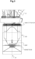
Fig. 3 ] est une vue schématique et partielle de la grue selon l'invention, illustrant sa structure support ; - [
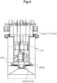
Fig. 4 ] est une autre vue schématique et partielle de la grue selon l'invention, illustrant sa structure support ; - [
Fig. 5 ] est une vue schématique et partielle de la grue selon l'invention, illustrant la structure des éléments roulants constitutifs des moyens paliers supérieurs ; - [
Fig. 6 ] est une vue schématique et en perspective d'un module de roulement constitutif des éléments roulants selon lafigure 5 ; - [
Fig. 7 ] est une vue schématique et en coupe d'un module de roulement constitutif des éléments roulants selon lafigure 5 ; - [
Fig. 8 ] est une vue schématique et en coupe des moyens paliers inférieurs. - Il est à noter que, sur ces figures, les éléments structurels et/ou fonctionnels communs aux différentes variantes peuvent présenter les mêmes références.
- La grue 1, telle que représentée sur les figures, consiste avantageusement en une grue pour le levage d'une charge supérieure à 20 tonnes (par exemple supérieure à 400 tonnes et jusqu'à au moins 10 000 tonnes, voire plus), en particulier pour application offshore (« offshore heavy lift »).
- De manière générale, la grue 1 est avantageusement une grue terrestre ou une grue offshore.
- De préférence, la grue 1 est dépourvue de contrepoids sur la partie rotative destinés à minimiser le transfert de moment de flexion.
- Tel que représenté de manière générale sur les
figures 1 à 3 , la grue 1 comprend : - une flèche 2, et
- une structure support 3, destinée à porter cette flèche 2.
- Comme illustré sur les
figures 3 et4 , la structure support 3 comprend : - un piédestal 5, formant stator, et
- un châssis porteur 6, formant rotor, portant la flèche 2 et logé dans le piédestal 5.
- Le piédestal 5 présente avantageusement une structure tubulaire ou une structure en fût (mâle), dans laquelle est rapporté / emmanché le châssis porteur 6 (femelle).
- Le piédestal 5 comporte avantageusement deux extrémités (
figure 3 ) : - une extrémité supérieure 51, située du côté de la flèche 2, et
- une extrémité inférieure 52, opposée.
- La châssis porteur 6 forme ici un insert, rapporté / emmanché dans le piédestal 5.
- Le châssis porteur 6 comporte avantageusement deux extrémités (
figure 3 ) : - une extrémité supérieure 61, portant la flèche 2, et
- une extrémité inférieure 62, opposée.
- La structure support 3 comporte encore deux extrémités :
- une extrémité supérieure 31, située du côté de la flèche 2, et
- une extrémité inférieure 32, opposée.
- La structure support 3 comprend encore des moyens paliers 7 pour l'assemblage entre le piédestal 5 et le châssis porteur 6.
- Les moyens paliers 7 définissent un axe de rotation 6' du châssis porteur 6 (et ainsi de la flèche 2), par rapport au piédestal 5, avantageusement un axe de rotation 6' vertical.
- La structure support 3 comprend également des moyens de manoeuvre en rotation 8, adaptés à piloter la rotation du châssis porteur 6 autour de son axe de rotation 6'.
- De préférence, les moyens de manoeuvre en rotation 8 consistent en une combinaison de moteurs 81, synchronisés entre eux, qui sont portés par le piédestal 5, et qui pilote la rotation du châssis porteur 6 par rapport au piédestal 5 (
figure 3 ). - Les moteurs 81 sont avantageusement répartis sur une partie de la circonférence du piédestal 5.
- Et, selon l'invention, tel que décrit ci-après en relation avec les
figures 3 et suivantes, les moyens paliers 7 sont répartis sur la hauteur de la structure support 3. - En l'espèce, les moyens paliers 7 comprennent :
- des moyens paliers supérieurs 71, situés du côté de la flèche 2 et avantageusement au niveau de l'extrémité supérieure 51 du piédestal 5, et
- des moyens paliers inférieurs 72, situés sous les moyens paliers supérieurs 71 et avantageusement au niveau de l'extrémité inférieure 62 du châssis porteur 6.
- De préférence, la construction totale des moyens paliers 7 est déterminée statiquement (donc non hyperstatique).
- De préférence encore, la charge axiale est transférée à travers la construction des moyens paliers inférieurs 72. Le moment est transféré à la fois par les moyens paliers supérieurs 71 et inférieurs 72.
- Les moyens paliers supérieurs 71 et inférieurs 72 peuvent être soit des roulements à rouleaux, soit des roulements à glissement, en métal ou en matière synthétique.
- Les moyens paliers supérieurs 71 se situent avantageusement au niveau de l'extrémité supérieure 51 du piédestal 5 (au sommet du piédestal 5). Ils sont avantageusement rapportés entre l'extrémité supérieure 51 du piédestal 5 et l'extrémité supérieure 61 du châssis porteur 6.
- En d'autres termes encore, les moyens paliers supérieurs 71 se situent avantageusement au niveau du point pivot de la flèche 2.
- Tel qu'illustré notamment sur la
figure 5 , les moyens paliers supérieurs 71 comprennent un roulement à contact radial 71 (désigné par le même repère 71 dans un souci de simplification) comprenant : - des éléments roulants 711, et
- un chemin de roulement cylindrique 712, lisse, coaxial à l'axe de rotation 6'.
- Et le roulement à contact radial 71 autorise un degré de liberté en translation longitudinal des éléments roulants 711 sur la hauteur du chemin de roulement cylindrique 712.
- Par « degré de liberté en translation longitudinal », dit encore « degré de liberté en translation axial », les éléments roulants 711 sont aptes à se déplacer selon une direction coaxiale à l'axe de rotation 6' du châssis porteur 6 (avantageusement verticalement), en translation par rapport au chemin de roulement cylindrique 712 fixe.
- Le plan général des éléments roulants 711, perpendiculaire à l'axe de rotation 6', est ainsi mobile sur la hauteur du chemin de roulement cylindrique 712 (entre ces extrémités supérieure et inférieure, opposées).
- Par « hauteur », on entend avantageusement une cote mesurée parallèlement à l'axe de rotation 6'.
- Le degré de liberté en translation longitudinal des éléments roulants 711 est avantageusement de 0,5 à 5 cm.
- La hauteur du chemin de roulement cylindrique 712 est ainsi supérieure à la hauteur des éléments roulants 711.
- En d'autres termes, lorsque la grue 1 est soumise à des charges, en particulier un mouvement de flexion et/ou une charge axiale, les éléments roulants 711 sont autorisés à se déplacer (ici verticalement) sur la hauteur du chemin de roulement cylindrique 712, tout au maintenant un guidage optimal en rotation.
- Le chemin de roulement cylindrique 712 consiste avantageusement en un tronçon tubulaire, à section circulaire, adapté à servir de surface de roulement pour les éléments roulants 711 lors de la rotation du châssis porteur 6 (et ainsi de la flèche 2), par rapport au piédestal 5.
- Ce chemin de roulement cylindrique 712 est avantageusement coaxial à l'axe de rotation 6' du châssis porteur 6.
- Les éléments roulants 711 sont choisis avantageusement parmi des rouleaux cylindriques 10, répartis sur au moins une rangée 11 (ou couronne).
- Chaque rouleaux cylindrique 10 comporte ici un axe longitudinal 10', formant son axe de rotation et s'étendant parallèlement à l'axe de rotation 6' du châssis porteur 6.
- Une rangée 11 de rouleaux cylindriques 10 s'étend avantageusement dans un plan perpendiculaire à l'axe de rotation 6'.
- En l'espèce, les éléments roulants 711 sont répartis sur deux rangées 11 (ou couronnes) superposées.
- Les rouleaux cylindriques 10 sont avantageusement reliés (au niveau de leurs extrémités longitudinales) pour former au moins une chaîne 12 de rouleaux cylindriques 10.
- Ces rouleaux cylindriques 10 sont avantageusement reliés par des maillons 101, pour maintenir l'écartement entre les rouleaux cylindriques 10 successifs (
figure 6 ). - En l'espèce, les éléments roulants 711 comportent avantageusement plusieurs modules de roulement 13 comportant chacun au moins une chaîne 12 de rouleaux cylindriques 10.
- Chaque module de roulement 13 comporte ici deux chaînes 12 de rouleaux cylindriques 10 superposées.
- Au sein de chaque module de roulement 13 et tel qu'illustré sur la
figure 7 , la chaîne 12 de rouleaux cylindriques 10 consiste en une chaîne 12 de rouleaux cylindriques 10 recirculant comportant : - un brin actif 121 coopérant avec le chemin de roulement cylindrique 712, et
- un brin retour 122.
- En l'espèce, le brin actif 121 définit une surface tangentielle 121' présentant une section en arc de cercle dont le rayon de courbure correspond au chemin de roulement cylindrique 712.
- Le brin retour 122 est avantageusement rectiligne.
- Pour cela, le module de roulement 13 comporte avantageusement un châssis support 131 comportant deux parties :
- une partie guidage 1311, guidant de la chaîne 12 de rouleaux cylindriques 10 recirculant et définissant la forme des brins 121, 122 de la chaîne 12 de rouleaux cylindriques 10 recirculant, et
- une partie montage 1312, ici concave et cylindrique, adaptée à son montage sur la structure support 3.
- Les modules de roulement 13 sont répartis, en série, sur la circonférence de l'axe de rotation 6', de manière juxtaposée les uns par rapport aux autres.
- Les modules de roulement 13, juxtaposés, forment ainsi une sorte de couronne d'éléments roulants 711.
- Les brins actifs 121 des modules de roulement 13 définissent ainsi ensemble une surface tangentielle 121' circulaire dont le rayon de courbure correspond au chemin de roulement cylindrique 712.
- Les brins actifs 121 des modules de roulement 13 définissent ainsi ensemble une surface tangentielle 121' circulaire qui est concentrique avec l'axe de rotation 6' du châssis porteur 6.
- De manière alternative, les éléments roulants 711 sont choisis avantageusement parmi une série de roues (non représentées), par exemple sous forme de chariots ou de bogies.
- De manière générale, les éléments roulants 711 sont avantageusement portés par le châssis porteur 6.
- Dans le cas de modules de roulement 13, la partie montage 1312 est assemblée avec le châssis porteur 6. Les brins actifs 121 des modules de roulement 13 définissent avantageusement ensemble une surface tangentielle 121' circulaire, intérieure, orientée vers la périphérie.
- Les brins actifs 121 des modules de roulement 13 définissent ainsi ensemble une surface tangentielle 121' circulaire, intérieure, orientée à l'opposé de l'axe de rotation 6'.
- Et le chemin de roulement cylindrique 712, extérieur, est porté par le piédestal 5 et est orienté vers l'axe de rotation 6'.
- Encore de manière générale, les moyens paliers inférieurs 72 se situent avantageusement au niveau de l'extrémité inférieure 62 du châssis porteur 6. Ils sont avantageusement rapportés entre l'extrémité inférieure 52 du piédestal 5 et l'extrémité inférieure 62 du châssis porteur 6.
- Les moyens paliers inférieurs 72 peuvent être constitués d'un ou plusieurs roulements / paliers, ayant un point central sphérique C3, de sorte à obtenir un seul point d'articulation.
- Les moyens paliers inférieurs 72 comportent avantageusement :
- un roulement à contact radial 721, avantageusement sus-jacent, et
- un palier de butée 722, avantageusement sous-jacent.
- Cette combinaison est intéressante en ce qu'elle permet une prise en charge optimale des efforts : l'effort radial est pris en charge par le roulement à contact radial 721 et l'effort axial est pris en charge par le palier de butée 722.
- Le roulement à contact radial 721 consiste avantageusement en un roulement à rotule 721, avantageusement choisi parmi les roulements à rotule sur rouleaux ou un palier de friction à rotule.
- Par exemple, un roulement à rotule sur rouleaux comporte deux rangées de rouleaux, une piste de roulement sphérique commune dans la bague extérieure 7212 et deux pistes dans des gorges continues sur la bague intérieure 7211.
- De manière générale, le roulement à rotule 721 accepte ainsi un déversement relatif, mouvement de la bague intérieure 7211 (rondelle-arbre) par rapport à la bague extérieure 7212 (rondelle-logement), perpendiculairement à l'axe de rotation 6'.
- Par exemple, l'angle de déversement admissible est de 1,5° à 2°.
- Le roulement à rotule 721 définit ainsi un point central C1, traversé par l'axe de rotation 6'.
- Le palier de butée 722 consiste avantageusement en un roulement à rouleaux concaves coniques.
- Ce roulement à rouleaux concaves coniques 722 définit également un point central C2, correspondant au sommet du cône défini par une directrice perpendiculaire à l'axe de rotation des rouleaux, traversé par l'axe de rotation 6'.
- Par exemple, le roulement à rouleaux concaves coniques 722 comporte une rangée de rouleaux, une piste de roulement tronconique (divergeant du bas vers le haut) dans la bague intérieure 7221 et une piste dans une gorge continue tronconique (avantageusement parallèle) sur la bague extérieure 7222.
- Le palier de butée 722 assure le maintien du châssis porteur 6 dans le sens axial et évite tout déplacement de long de son axe.
- Les points centraux C1 et C2 sont avantageusement confondus, définissant un point central commun C3 correspondant au point central sphérique C3.
- Le point central commun C3 est avantageusement traversé par l'axe de rotation 6'.
- De manière générale, les moyens de manoeuvre en rotation 8 sont avantageusement implantés au niveau des moyens paliers inférieurs 72 précités.
- Les moteurs 81 des moyens de manoeuvre en rotation 8 coopèrent avantageusement avec une roue dentée 82 équipant l'extrémité inférieure 62 du châssis porteur 6 (
figure 4 ). - De manière générale, tel que représenté sur la
figure 1 , la grue 1 équipe avantageusement un engin E pour application offshore, par exemple un navire pour service d'opération en parc éolien (« wind farm Service Operation Vessels » ou SOVs). - Dans le cas d'un navire (
figure 1 ), le piédestal 5 est avantageusement fixé sur un pont P de l'engin E, faisant saillie au-dessus de ce pont P. - Et les moyens paliers supérieurs 71 se situent au-dessus de ce pont P.
- Les moyens paliers inférieurs 72 peuvent présenter différentes localisations par rapport à ce pont P.
- Les moyens paliers inférieurs 72 peuvent se situer :
- au-dessus dudit pont P,
- au niveau dudit pont P, ou
- au-dessous dudit pont P.
- De manière générale, la grue 1 selon l'invention présente différents avantages :
- les moyens paliers sont plus petits en diamètre que les solutions de l'art antérieur, ce qui réduit l'encombrement de la grue et augmente ainsi l'espace de pont pour la cargaison ;
- la connexion boulonnée, qui est utilisée dans une construction à palier pivotant unique, est éliminée ; le risque associé à cette connexion, considérée comme une préoccupation majeure, est donc éliminé ;
- la hauteur du piédestal est inférieure à la hauteur du mât d'une grue à mât (mast crane) et le piédestal peut être plus facilement démonté pour être encore plus bas, ce qui permet au navire de passer les ponts dans les principales voies maritimes, comme le Pont du Bosphore à l'entrée de la mer Noire ;
- la construction des moyens paliers a un coût inférieur et une meilleure productibilité qu'une solution de roulement simple ;
- les moyens paliers sont situés à l'intérieur du piédestal, entre la châssis porteur et le piédestal ; les moyens paliers se trouvent ainsi dans un environnement protégé plutôt qu'en mer ouverte, ce qui est le cas pour les grues à bogie et à mât.
- Bien entendu, diverses autres modifications peuvent être apportées à l'invention dans le cadre des revendications annexées.
Claims (9)
- Grue, avantageusement pour le levage d'une charge supérieure à 20 tonnes, en particulier pour application offshore,laquelle grue comprend :- une flèche (2),- une structure support (3), destinée à porter ladite flèche (2),laquelle structure support (3) comprend :- un piédestal (5), formant stator, et- un châssis porteur (6), formant rotor, portant ladite flèche (2) et logé dans ledit piédestal (5),- des moyens paliers (7) pour l'assemblage entre ledit piédestal (5) et ledit châssis porteur (6), définissant un axe de rotation (6') dudit châssis porteur (6) par rapport audit piédestal (5), avantageusement un axe de rotation (6') vertical,- des moyens de manoeuvre en rotation (8), adaptés à piloter la rotation dudit châssis porteur (6) autour dudit axe de rotation (6'), dans laquelle lesdites moyens paliers (7) sont répartis sur la hauteur de ladite structure support (3) et comprennent :- des moyens paliers supérieurs (71), situés du côté de la flèche (2) et avantageusement au niveau d'une extrémité supérieure (51) dudit piédestal (5), et- des moyens paliers inférieurs (72), situés sous les moyens paliers supérieurs (71) et avantageusement au niveau d'une extrémité inférieure (62) du châssis porteur (6), lesquels moyens paliers supérieurs (71) comprennent un roulement à contact radial (71) comprenant :- des éléments roulants (711), et- un chemin de roulement cylindrique (712), lisse, coaxial à l'axe de rotation (6'),ledit roulement à contact radial (71) autorisant un degré de liberté en translation longitudinal desdits éléments roulants (711) sur la hauteur dudit chemin de roulement cylindrique (712),lequel roulement à contact radial (71) comprend des éléments roulants (711) choisis parmi des rouleaux cylindriques (10), répartis sur au moins une rangée (11),lesquels moyens paliers inférieurs (72) comportent : U- un roulement à contact radial (721), et U- un palier de butée (722), Ucaractérisée en ce que les rouleaux cylindriques (10) sont reliés pour former au moins une chaîne (12) de rouleaux cylindriques (10),lesquels moyens paliers supérieurs (71) comportent plusieurs modules de roulement (13) comportant chacun ladite au moins une chaîne (12) de rouleaux cylindriques (10), en ce que, au sein de chaque module de roulement (13), la chaîne (12) de rouleaux cylindriques (10) forme une chaîne (12) de rouleaux cylindriques (10) recirculant qui comporte :- un brin actif (121) coopérant avec le chemin de roulement cylindrique (712), et- un brin retour (122),lesquels modules de roulement (13) sont répartis sur la circonférence de l'axe de rotation (6'),lequel roulement à contact radial (721) consiste en un roulement à rotule (721),en ce que le palier de butée (722) consiste en un roulement à rouleaux concaves coniques, eten ce que ledit roulement à rotule (721) et ledit roulement à rouleaux coniques (722) comportent un point central commun (C3) traversé par l'axe de rotation (6').
- Grue, selon la revendication 1, caractérisée en ce que les moyens paliers inférieurs (72) comportent :- un roulement à contact radial (721), sus-jacent, et- un palier de butée (722), sous-jacent.
- Grue, selon l'une quelconque des revendications 1 ou 2, caractérisée en ce que le roulement à contact radial (721) consiste en un roulement à rotule (721) choisi parmi les roulements à rotule sur rouleaux ou un palier de friction à rotule.
- Grue, selon l'une quelconque des revendications 1 à 3, caractérisée en ce que les éléments roulants (711) sont portés par le châssis porteur (6), et
en ce que le chemin de roulement cylindrique (712) est porté par le piédestal (5) et est orienté vers l'axe de rotation (6'). - Grue, selon l'une quelconque des revendications 1 à 4, caractérisée en ce que les moyens paliers inférieurs (72) comportent un point central sphérique (C3), de sorte à obtenir un seul point d'articulation.
- Grue, selon l'une quelconque des revendications 1 à 5, caractérisée en ce que les moyens de manoeuvre en rotation (8) sont implantés au niveau des moyens paliers inférieurs (72).
- Grue, selon l'une quelconque des revendications 1 à 6, caractérisée en ce que ladite grue (1) est une grue terrestre ou une grue offshore.
- Engin pour application offshore, équipé d'une grue (1) selon l'une quelconque des revendications 1 à 7, par exemple un navire pour service d'opération en parc éolien.
- Engin selon la revendication 8, consistant en un navire, dans lequel le piédestal (5) est fixé sur un pont (P) dudit engin (E), faisant saillie au-dessus dudit pont (P),en ce que les moyens paliers supérieurs (71) se situent au-dessus dudit pont (P),et en ce que les moyens paliers inférieurs (72) se situent au-dessus, au niveau ou au-dessous dudit pont (P).
Priority Applications (1)
| Application Number | Priority Date | Filing Date | Title |
|---|---|---|---|
| EP24203064.1A EP4512763A1 (fr) | 2021-03-12 | 2022-03-11 | Grue, en particulier pour application offshore |
Applications Claiming Priority (1)
| Application Number | Priority Date | Filing Date | Title |
|---|---|---|---|
| FR2102455A FR3120621B1 (fr) | 2021-03-12 | 2021-03-12 | Grue, en particulier pour application offshore |
Related Child Applications (2)
| Application Number | Title | Priority Date | Filing Date |
|---|---|---|---|
| EP24203064.1A Division EP4512763A1 (fr) | 2021-03-12 | 2022-03-11 | Grue, en particulier pour application offshore |
| EP24203064.1A Division-Into EP4512763A1 (fr) | 2021-03-12 | 2022-03-11 | Grue, en particulier pour application offshore |
Publications (2)
| Publication Number | Publication Date |
|---|---|
| EP4056519A1 EP4056519A1 (fr) | 2022-09-14 |
| EP4056519B1 true EP4056519B1 (fr) | 2024-11-20 |
Family
ID=75439076
Family Applications (2)
| Application Number | Title | Priority Date | Filing Date |
|---|---|---|---|
| EP24203064.1A Pending EP4512763A1 (fr) | 2021-03-12 | 2022-03-11 | Grue, en particulier pour application offshore |
| EP22161563.6A Active EP4056519B1 (fr) | 2021-03-12 | 2022-03-11 | Grue, en particulier pour application offshore |
Family Applications Before (1)
| Application Number | Title | Priority Date | Filing Date |
|---|---|---|---|
| EP24203064.1A Pending EP4512763A1 (fr) | 2021-03-12 | 2022-03-11 | Grue, en particulier pour application offshore |
Country Status (6)
| Country | Link |
|---|---|
| US (1) | US11981549B2 (fr) |
| EP (2) | EP4512763A1 (fr) |
| CN (1) | CN115072593A (fr) |
| BR (1) | BR102022004188A2 (fr) |
| DK (1) | DK4056519T3 (fr) |
| FR (1) | FR3120621B1 (fr) |
Citations (2)
| Publication number | Priority date | Publication date | Assignee | Title |
|---|---|---|---|---|
| CN101343021A (zh) * | 2008-08-20 | 2009-01-14 | 大连华锐股份有限公司 | 大型全回转海上平台起重机 |
| FR2950315A1 (fr) * | 2009-09-24 | 2011-03-25 | Technip France | Installation notamment pour la production et le traitement de fluides comprenant une unite flottante pourvue d'un systeme d'amarrage rotatif a point unique par l'intermediaire d'une tourelle montee en pivot dans un puits de l'unite flottante |
Family Cites Families (26)
| Publication number | Priority date | Publication date | Assignee | Title |
|---|---|---|---|---|
| US253679A (en) * | 1882-02-14 | of brunswick | ||
| US575618A (en) * | 1897-01-19 | Roller-bearing | ||
| US560322A (en) * | 1896-05-19 | Antifriction-bearing | ||
| US667684A (en) * | 1899-07-28 | 1901-02-12 | Gerhard Deharde | Antifriction-bearing. |
| GB562517A (en) * | 1943-01-20 | 1944-07-05 | Guy Taite Shoosmith | Luffing and slewing crane |
| GB1016701A (en) * | 1962-03-08 | 1966-01-12 | Babcock & Wilcox Ltd | Improvements in devices having rotatable parts,such as cranes or radio telescopes |
| DE2647588C2 (de) * | 1976-10-21 | 1985-06-13 | Hoesch Ag, 4600 Dortmund | Großwälzlager |
| US4248488A (en) * | 1979-02-07 | 1981-02-03 | Rotek Incorporated | Quick disconnect bearing mount for construction machinery |
| US4395140A (en) * | 1981-10-02 | 1983-07-26 | Rotek Incorporated | Bearing mounting with hydraulic fastening means for cranes and the like |
| JPS59219519A (ja) * | 1983-05-26 | 1984-12-10 | Hiroshi Teramachi | 直線摺動用ロ−ラ−ベアリングユニツト |
| NL184414C (nl) * | 1985-06-13 | 1989-07-17 | Kenz Kraantechniek B V | Kraan voor toepassing op booreilanden en dergelijke. |
| EP1251287B1 (fr) * | 1996-05-13 | 2006-04-26 | Thk Co. Ltd. | Palier linéaire à rouleaux |
| US6203200B1 (en) * | 1999-07-16 | 2001-03-20 | Hiroshi Teramachi | Linear motion guide apparatus employing a roller train |
| DE19942984A1 (de) * | 1999-09-09 | 2001-03-15 | Schaeffler Waelzlager Ohg | Radial-Axial-Lagereinheit |
| TWI267590B (en) * | 2003-12-05 | 2006-12-01 | Nsk Ltd | Linear guide device |
| US7632017B2 (en) * | 2004-03-16 | 2009-12-15 | Nsk Ltd. | Linear guide |
| US8540092B2 (en) * | 2007-01-17 | 2013-09-24 | Itrec B.V. | Hoisting crane with annular bearing structure |
| US8002472B2 (en) * | 2008-06-30 | 2011-08-23 | Nucor Corporation | Slew bearing system |
| DE102009004991A1 (de) * | 2009-01-14 | 2010-07-15 | Imo Holding Gmbh | Windkraftanlage |
| CN102502423B (zh) * | 2011-10-14 | 2014-01-15 | 三一集团有限公司 | 一种海上风电安装船用起重机 |
| DE102012025600A1 (de) * | 2012-12-31 | 2014-07-03 | Imo Holding Gmbh | Vorrichtung zur drehbaren Kopplung zweier Anlagen- oder Maschinenteile |
| JP5819893B2 (ja) * | 2013-05-20 | 2015-11-24 | Thk株式会社 | 複列ローラ軸受 |
| US8997611B1 (en) * | 2013-10-11 | 2015-04-07 | Tri Tool Inc. | Bearing assembly for use with a rotating machining device |
| NL2011922C2 (en) * | 2013-12-09 | 2015-06-11 | Itrec Bv | Hoisting crane and method for refurbishing such a hoisting crane. |
| US9394944B2 (en) * | 2014-07-08 | 2016-07-19 | Caterpillar Global Mining Llc | Thrust rail and swing gear assembly for a mining vehicle |
| US11725633B2 (en) * | 2017-03-28 | 2023-08-15 | General Electric Company | Pitch bearing for a wind turbine |
-
2021
- 2021-03-12 FR FR2102455A patent/FR3120621B1/fr active Active
-
2022
- 2022-03-07 BR BR102022004188-1A patent/BR102022004188A2/pt unknown
- 2022-03-11 US US17/692,976 patent/US11981549B2/en active Active
- 2022-03-11 EP EP24203064.1A patent/EP4512763A1/fr active Pending
- 2022-03-11 DK DK22161563.6T patent/DK4056519T3/da active
- 2022-03-11 EP EP22161563.6A patent/EP4056519B1/fr active Active
- 2022-03-11 CN CN202210236738.2A patent/CN115072593A/zh active Pending
Patent Citations (2)
| Publication number | Priority date | Publication date | Assignee | Title |
|---|---|---|---|---|
| CN101343021A (zh) * | 2008-08-20 | 2009-01-14 | 大连华锐股份有限公司 | 大型全回转海上平台起重机 |
| FR2950315A1 (fr) * | 2009-09-24 | 2011-03-25 | Technip France | Installation notamment pour la production et le traitement de fluides comprenant une unite flottante pourvue d'un systeme d'amarrage rotatif a point unique par l'intermediaire d'une tourelle montee en pivot dans un puits de l'unite flottante |
Also Published As
| Publication number | Publication date |
|---|---|
| EP4512763A1 (fr) | 2025-02-26 |
| US11981549B2 (en) | 2024-05-14 |
| DK4056519T3 (da) | 2025-02-03 |
| BR102022004188A2 (pt) | 2022-09-20 |
| FR3120621A1 (fr) | 2022-09-16 |
| CN115072593A (zh) | 2022-09-20 |
| FR3120621B1 (fr) | 2023-05-12 |
| EP4056519A1 (fr) | 2022-09-14 |
| US20220289531A1 (en) | 2022-09-15 |
Similar Documents
| Publication | Publication Date | Title |
|---|---|---|
| EP3409942B1 (fr) | Dispositif et navire de maintenance pour éolienne offshore | |
| EP2516248B1 (fr) | Installation notamment pour la production et le traitement de fluides, du type comprenant une unité flottante, pourvu d'un système d'amarrage à point unique | |
| EP1741940B1 (fr) | Palier à roulements tonneaux | |
| EP2488768B1 (fr) | Roulement a billes et butee de suspension associee | |
| EP4144918A1 (fr) | Système pour le maintien temporaire, au cours des opérations de battage, d'un pieu de fondation destiné à recevoir le mat d'une éolienne off-shore | |
| FR2746869A1 (fr) | Agencement de montage pour des elements rotatifs, en particulier les satellites d'un train planetaire | |
| EP4512763A1 (fr) | Grue, en particulier pour application offshore | |
| FR2953188A1 (fr) | Installation notamment pour la production et le traitement de fluides comprenant une unite flottante pourvue d'un systeme d'amarrage rotatif a point unique par l'intermediaire d'une tourelle montee en pivot dans un puits de l'unite flottante | |
| FR2531055A1 (fr) | Grue de levage | |
| FR2560864A1 (fr) | Montage de fleches telescopiques | |
| FR3120003A1 (fr) | Robot mobile coopératif en forme de colonne | |
| CA3034944A1 (fr) | Dispositif d`appui et de guidage d`un cable tracteur de vehicule d`une installation de transport, articulation d`un tel dispositif et procede de fabrication du dispositif | |
| FR2950314A1 (fr) | Systeme adapte pour le transfert de fortes charges notamment entre une unite flottante a tourelle montee en pivot dans l'unite flottante et amarre sur le fond marin | |
| EP4029821A1 (fr) | Chariot de convoyage aerien de charges | |
| FR3015915B1 (fr) | Chassis de vehicule omnidirectionnel comportant des corps de chassis deplacables l'un par rapport a l'autre | |
| EP4269695B1 (fr) | Système de maintien temporaire, pour le maintien temporaire, au cours des opérations de battage, d'un pieu de fondation destiné à recevoir le mat d'une éolienne off-shore | |
| EP4408734B1 (fr) | Système et procédé de mise à l'eau d'une charge lourde | |
| FR2553731A1 (fr) | Dispositif pour le transport par etapes de charges lourdes | |
| FR2748265A1 (fr) | Moufle de support et de manutention d'une charge, dispositif de manutention correspondant et son utilisation | |
| EP0165854A1 (fr) | Dispositif de supportage d'un organe très lourd déplaçable en translation ou en rotation sur une socle fixe | |
| FR2994112A1 (fr) | Carrousel rotatif | |
| WO2019025086A1 (fr) | Ber basculant | |
| CA1246940A (fr) | Systeme de liaison entre un corps principal et une superstructure | |
| FR2655634A1 (fr) | Verin a lanterne a tiges creuses telescopiques et son utilisation. | |
| EP4653374A1 (fr) | Engin pour application offshore, comportant un pont équipé d'une grue à flèche articulée |
Legal Events
| Date | Code | Title | Description |
|---|---|---|---|
| PUAI | Public reference made under article 153(3) epc to a published international application that has entered the european phase |
Free format text: ORIGINAL CODE: 0009012 |
|
| STAA | Information on the status of an ep patent application or granted ep patent |
Free format text: STATUS: THE APPLICATION HAS BEEN PUBLISHED |
|
| AK | Designated contracting states |
Kind code of ref document: A1 Designated state(s): AL AT BE BG CH CY CZ DE DK EE ES FI FR GB GR HR HU IE IS IT LI LT LU LV MC MK MT NL NO PL PT RO RS SE SI SK SM TR |
|
| STAA | Information on the status of an ep patent application or granted ep patent |
Free format text: STATUS: REQUEST FOR EXAMINATION WAS MADE |
|
| 17P | Request for examination filed |
Effective date: 20230313 |
|
| RBV | Designated contracting states (corrected) |
Designated state(s): AL AT BE BG CH CY CZ DE DK EE ES FI FR GB GR HR HU IE IS IT LI LT LU LV MC MK MT NL NO PL PT RO RS SE SI SK SM TR |
|
| TPAC | Observations filed by third parties |
Free format text: ORIGINAL CODE: EPIDOSNTIPA |
|
| P01 | Opt-out of the competence of the unified patent court (upc) registered |
Effective date: 20230518 |
|
| GRAP | Despatch of communication of intention to grant a patent |
Free format text: ORIGINAL CODE: EPIDOSNIGR1 |
|
| STAA | Information on the status of an ep patent application or granted ep patent |
Free format text: STATUS: GRANT OF PATENT IS INTENDED |
|
| TPAC | Observations filed by third parties |
Free format text: ORIGINAL CODE: EPIDOSNTIPA |
|
| INTG | Intention to grant announced |
Effective date: 20240515 |
|
| GRAJ | Information related to disapproval of communication of intention to grant by the applicant or resumption of examination proceedings by the epo deleted |
Free format text: ORIGINAL CODE: EPIDOSDIGR1 |
|
| GRAP | Despatch of communication of intention to grant a patent |
Free format text: ORIGINAL CODE: EPIDOSNIGR1 |
|
| INTG | Intention to grant announced |
Effective date: 20240723 |
|
| GRAS | Grant fee paid |
Free format text: ORIGINAL CODE: EPIDOSNIGR3 |
|
| GRAA | (expected) grant |
Free format text: ORIGINAL CODE: 0009210 |
|
| STAA | Information on the status of an ep patent application or granted ep patent |
Free format text: STATUS: THE PATENT HAS BEEN GRANTED |
|
| AK | Designated contracting states |
Kind code of ref document: B1 Designated state(s): AL AT BE BG CH CY CZ DE DK EE ES FI FR GB GR HR HU IE IS IT LI LT LU LV MC MK MT NL NO PL PT RO RS SE SI SK SM TR |
|
| REG | Reference to a national code |
Ref country code: GB Ref legal event code: FG4D Free format text: NOT ENGLISH |
|
| REG | Reference to a national code |
Ref country code: CH Ref legal event code: EP |
|
| REG | Reference to a national code |
Ref country code: DE Ref legal event code: R096 Ref document number: 602022007787 Country of ref document: DE |
|
| REG | Reference to a national code |
Ref country code: IE Ref legal event code: FG4D Free format text: LANGUAGE OF EP DOCUMENT: FRENCH |
|
| REG | Reference to a national code |
Ref country code: NL Ref legal event code: FP |
|
| REG | Reference to a national code |
Ref country code: DK Ref legal event code: T3 Effective date: 20250131 |
|
| REG | Reference to a national code |
Ref country code: LT Ref legal event code: MG9D |
|
| PG25 | Lapsed in a contracting state [announced via postgrant information from national office to epo] |
Ref country code: IS Free format text: LAPSE BECAUSE OF FAILURE TO SUBMIT A TRANSLATION OF THE DESCRIPTION OR TO PAY THE FEE WITHIN THE PRESCRIBED TIME-LIMIT Effective date: 20250320 Ref country code: HR Free format text: LAPSE BECAUSE OF FAILURE TO SUBMIT A TRANSLATION OF THE DESCRIPTION OR TO PAY THE FEE WITHIN THE PRESCRIBED TIME-LIMIT Effective date: 20241120 Ref country code: PT Free format text: LAPSE BECAUSE OF FAILURE TO SUBMIT A TRANSLATION OF THE DESCRIPTION OR TO PAY THE FEE WITHIN THE PRESCRIBED TIME-LIMIT Effective date: 20250320 |
|
| PG25 | Lapsed in a contracting state [announced via postgrant information from national office to epo] |
Ref country code: FI Free format text: LAPSE BECAUSE OF FAILURE TO SUBMIT A TRANSLATION OF THE DESCRIPTION OR TO PAY THE FEE WITHIN THE PRESCRIBED TIME-LIMIT Effective date: 20241120 |
|
| REG | Reference to a national code |
Ref country code: AT Ref legal event code: MK05 Ref document number: 1743434 Country of ref document: AT Kind code of ref document: T Effective date: 20241120 |
|
| PG25 | Lapsed in a contracting state [announced via postgrant information from national office to epo] |
Ref country code: BG Free format text: LAPSE BECAUSE OF FAILURE TO SUBMIT A TRANSLATION OF THE DESCRIPTION OR TO PAY THE FEE WITHIN THE PRESCRIBED TIME-LIMIT Effective date: 20241120 |
|
| PG25 | Lapsed in a contracting state [announced via postgrant information from national office to epo] |
Ref country code: ES Free format text: LAPSE BECAUSE OF FAILURE TO SUBMIT A TRANSLATION OF THE DESCRIPTION OR TO PAY THE FEE WITHIN THE PRESCRIBED TIME-LIMIT Effective date: 20241120 |
|
| PG25 | Lapsed in a contracting state [announced via postgrant information from national office to epo] |
Ref country code: AT Free format text: LAPSE BECAUSE OF FAILURE TO SUBMIT A TRANSLATION OF THE DESCRIPTION OR TO PAY THE FEE WITHIN THE PRESCRIBED TIME-LIMIT Effective date: 20241120 Ref country code: LV Free format text: LAPSE BECAUSE OF FAILURE TO SUBMIT A TRANSLATION OF THE DESCRIPTION OR TO PAY THE FEE WITHIN THE PRESCRIBED TIME-LIMIT Effective date: 20241120 Ref country code: GR Free format text: LAPSE BECAUSE OF FAILURE TO SUBMIT A TRANSLATION OF THE DESCRIPTION OR TO PAY THE FEE WITHIN THE PRESCRIBED TIME-LIMIT Effective date: 20250221 |
|
| PG25 | Lapsed in a contracting state [announced via postgrant information from national office to epo] |
Ref country code: PL Free format text: LAPSE BECAUSE OF FAILURE TO SUBMIT A TRANSLATION OF THE DESCRIPTION OR TO PAY THE FEE WITHIN THE PRESCRIBED TIME-LIMIT Effective date: 20241120 |
|
| PG25 | Lapsed in a contracting state [announced via postgrant information from national office to epo] |
Ref country code: RS Free format text: LAPSE BECAUSE OF FAILURE TO SUBMIT A TRANSLATION OF THE DESCRIPTION OR TO PAY THE FEE WITHIN THE PRESCRIBED TIME-LIMIT Effective date: 20250220 |
|
| PG25 | Lapsed in a contracting state [announced via postgrant information from national office to epo] |
Ref country code: SM Free format text: LAPSE BECAUSE OF FAILURE TO SUBMIT A TRANSLATION OF THE DESCRIPTION OR TO PAY THE FEE WITHIN THE PRESCRIBED TIME-LIMIT Effective date: 20241120 |
|
| PG25 | Lapsed in a contracting state [announced via postgrant information from national office to epo] |
Ref country code: EE Free format text: LAPSE BECAUSE OF FAILURE TO SUBMIT A TRANSLATION OF THE DESCRIPTION OR TO PAY THE FEE WITHIN THE PRESCRIBED TIME-LIMIT Effective date: 20241120 |
|
| PG25 | Lapsed in a contracting state [announced via postgrant information from national office to epo] |
Ref country code: RO Free format text: LAPSE BECAUSE OF FAILURE TO SUBMIT A TRANSLATION OF THE DESCRIPTION OR TO PAY THE FEE WITHIN THE PRESCRIBED TIME-LIMIT Effective date: 20241120 |
|
| PG25 | Lapsed in a contracting state [announced via postgrant information from national office to epo] |
Ref country code: SK Free format text: LAPSE BECAUSE OF FAILURE TO SUBMIT A TRANSLATION OF THE DESCRIPTION OR TO PAY THE FEE WITHIN THE PRESCRIBED TIME-LIMIT Effective date: 20241120 |
|
| PG25 | Lapsed in a contracting state [announced via postgrant information from national office to epo] |
Ref country code: CZ Free format text: LAPSE BECAUSE OF FAILURE TO SUBMIT A TRANSLATION OF THE DESCRIPTION OR TO PAY THE FEE WITHIN THE PRESCRIBED TIME-LIMIT Effective date: 20241120 |
|
| REG | Reference to a national code |
Ref country code: DE Ref legal event code: R097 Ref document number: 602022007787 Country of ref document: DE |
|
| PG25 | Lapsed in a contracting state [announced via postgrant information from national office to epo] |
Ref country code: SE Free format text: LAPSE BECAUSE OF FAILURE TO SUBMIT A TRANSLATION OF THE DESCRIPTION OR TO PAY THE FEE WITHIN THE PRESCRIBED TIME-LIMIT Effective date: 20241120 |
|
| PLBE | No opposition filed within time limit |
Free format text: ORIGINAL CODE: 0009261 |
|
| STAA | Information on the status of an ep patent application or granted ep patent |
Free format text: STATUS: NO OPPOSITION FILED WITHIN TIME LIMIT |
|
| PG25 | Lapsed in a contracting state [announced via postgrant information from national office to epo] |
Ref country code: MC Free format text: LAPSE BECAUSE OF FAILURE TO SUBMIT A TRANSLATION OF THE DESCRIPTION OR TO PAY THE FEE WITHIN THE PRESCRIBED TIME-LIMIT Effective date: 20241120 |
|
| 26N | No opposition filed |
Effective date: 20250821 |
|
| REG | Reference to a national code |
Ref country code: CH Ref legal event code: H13 Free format text: ST27 STATUS EVENT CODE: U-0-0-H10-H13 (AS PROVIDED BY THE NATIONAL OFFICE) Effective date: 20251023 |
|
| PG25 | Lapsed in a contracting state [announced via postgrant information from national office to epo] |
Ref country code: LU Free format text: LAPSE BECAUSE OF NON-PAYMENT OF DUE FEES Effective date: 20250311 |
|
| REG | Reference to a national code |
Ref country code: BE Ref legal event code: MM Effective date: 20250331 |
|
| PGFP | Annual fee paid to national office [announced via postgrant information from national office to epo] |
Ref country code: DK Payment date: 20251226 Year of fee payment: 5 |
|
| PGFP | Annual fee paid to national office [announced via postgrant information from national office to epo] |
Ref country code: FR Payment date: 20251216 Year of fee payment: 5 |
|
| PG25 | Lapsed in a contracting state [announced via postgrant information from national office to epo] |
Ref country code: BE Free format text: LAPSE BECAUSE OF NON-PAYMENT OF DUE FEES Effective date: 20250331 |
|
| PG25 | Lapsed in a contracting state [announced via postgrant information from national office to epo] |
Ref country code: CH Free format text: LAPSE BECAUSE OF NON-PAYMENT OF DUE FEES Effective date: 20250331 |
|
| PG25 | Lapsed in a contracting state [announced via postgrant information from national office to epo] |
Ref country code: IE Free format text: LAPSE BECAUSE OF NON-PAYMENT OF DUE FEES Effective date: 20250311 |
|
| PGFP | Annual fee paid to national office [announced via postgrant information from national office to epo] |
Ref country code: GB Payment date: 20260115 Year of fee payment: 5 |
|
| PGFP | Annual fee paid to national office [announced via postgrant information from national office to epo] |
Ref country code: NO Payment date: 20260323 Year of fee payment: 5 Ref country code: DE Payment date: 20251218 Year of fee payment: 5 |
|
| PGFP | Annual fee paid to national office [announced via postgrant information from national office to epo] |
Ref country code: IT Payment date: 20260107 Year of fee payment: 5 |
|
| PGFP | Annual fee paid to national office [announced via postgrant information from national office to epo] |
Ref country code: NL Payment date: 20260319 Year of fee payment: 5 |