EP4056510B1 - Verfahren zur erkennung von aufzugsbremsenverschleiss, erkennungsvorrichtung und aufzugsbremse - Google Patents
Verfahren zur erkennung von aufzugsbremsenverschleiss, erkennungsvorrichtung und aufzugsbremse Download PDFInfo
- Publication number
- EP4056510B1 EP4056510B1 EP21213816.8A EP21213816A EP4056510B1 EP 4056510 B1 EP4056510 B1 EP 4056510B1 EP 21213816 A EP21213816 A EP 21213816A EP 4056510 B1 EP4056510 B1 EP 4056510B1
- Authority
- EP
- European Patent Office
- Prior art keywords
- elevator
- elevator brake
- inductance
- electromagnetic
- state
- Prior art date
- Legal status (The legal status is an assumption and is not a legal conclusion. Google has not performed a legal analysis and makes no representation as to the accuracy of the status listed.)
- Active
Links
Images


Classifications
-
- B—PERFORMING OPERATIONS; TRANSPORTING
- B66—HOISTING; LIFTING; HAULING
- B66B—ELEVATORS; ESCALATORS OR MOVING WALKWAYS
- B66B1/00—Control systems of elevators in general
- B66B1/24—Control systems with regulation, i.e. with retroactive action, for influencing travelling speed, acceleration, or deceleration
- B66B1/28—Control systems with regulation, i.e. with retroactive action, for influencing travelling speed, acceleration, or deceleration electrical
- B66B1/32—Control systems with regulation, i.e. with retroactive action, for influencing travelling speed, acceleration, or deceleration electrical effective on braking devices, e.g. acting on electrically controlled brakes
-
- B—PERFORMING OPERATIONS; TRANSPORTING
- B66—HOISTING; LIFTING; HAULING
- B66B—ELEVATORS; ESCALATORS OR MOVING WALKWAYS
- B66B5/00—Applications of checking, fault-correcting, or safety devices in elevators
- B66B5/0006—Monitoring devices or performance analysers
- B66B5/0018—Devices monitoring the operating condition of the elevator system
- B66B5/0025—Devices monitoring the operating condition of the elevator system for maintenance or repair
-
- B—PERFORMING OPERATIONS; TRANSPORTING
- B66—HOISTING; LIFTING; HAULING
- B66B—ELEVATORS; ESCALATORS OR MOVING WALKWAYS
- B66B5/00—Applications of checking, fault-correcting, or safety devices in elevators
- B66B5/0006—Monitoring devices or performance analysers
- B66B5/0018—Devices monitoring the operating condition of the elevator system
- B66B5/0031—Devices monitoring the operating condition of the elevator system for safety reasons
-
- B—PERFORMING OPERATIONS; TRANSPORTING
- B66—HOISTING; LIFTING; HAULING
- B66B—ELEVATORS; ESCALATORS OR MOVING WALKWAYS
- B66B5/00—Applications of checking, fault-correcting, or safety devices in elevators
- B66B5/0006—Monitoring devices or performance analysers
- B66B5/0037—Performance analysers
-
- B—PERFORMING OPERATIONS; TRANSPORTING
- B66—HOISTING; LIFTING; HAULING
- B66B—ELEVATORS; ESCALATORS OR MOVING WALKWAYS
- B66B5/00—Applications of checking, fault-correcting, or safety devices in elevators
- B66B5/0087—Devices facilitating maintenance, repair or inspection tasks
-
- B—PERFORMING OPERATIONS; TRANSPORTING
- B66—HOISTING; LIFTING; HAULING
- B66D—CAPSTANS; WINCHES; TACKLES, e.g. PULLEY BLOCKS; HOISTS
- B66D5/00—Braking or detent devices characterised by application to lifting or hoisting gear, e.g. for controlling the lowering of loads
- B66D5/02—Crane, lift hoist, or winch brakes operating on drums, barrels, or ropes
- B66D5/12—Crane, lift hoist, or winch brakes operating on drums, barrels, or ropes with axial effect
- B66D5/14—Crane, lift hoist, or winch brakes operating on drums, barrels, or ropes with axial effect embodying discs
-
- B—PERFORMING OPERATIONS; TRANSPORTING
- B66—HOISTING; LIFTING; HAULING
- B66B—ELEVATORS; ESCALATORS OR MOVING WALKWAYS
- B66B5/00—Applications of checking, fault-correcting, or safety devices in elevators
- B66B5/02—Applications of checking, fault-correcting, or safety devices in elevators responsive to abnormal operating conditions
- B66B5/16—Braking or catch devices operating between cars, cages, or skips and fixed guide elements or surfaces in hoistway or well
- B66B5/18—Braking or catch devices operating between cars, cages, or skips and fixed guide elements or surfaces in hoistway or well and applying frictional retarding forces
Definitions
- the present disclosure relates to the technical field of elevators, in particular to an elevator brake wear detection method, an elevator brake wear detection device and an elevator brake.
- An elevator brake is a safety braking device in an elevator. It plays an important role in ensuring the safe operation of elevators and the personal safety of passengers.
- An existing elevator system 100 is shown in FIG. 1 .
- an elevator power device 20 such as a traction machine, etc.
- an elevator brake 10 and other devices may be disposed in an elevator machine room 400, and the elevator power device 20 is connected with an elevator car 200 through a rope 300 so as to provide power to the elevator car 200 so that the elevator car 200 is driven to move up and down in an elevator hoistway, and to stop at the passenger's target floor by operating the elevator brake, such as Fa, Fb or Fc, etc., shown in FIG. 1 .
- the elevator car can also be safely braked through the elevator brake.
- the elevator brake mainly includes a fixed part 1 and a moving part 2 which is capable of moving relative to the fixed part 1 according to operational requirements.
- the fixed part 1 can be fixedly installed in the elevator machine room 400, and a force F1 is provided by a component 5 (such as a spring, etc.) arranged between the fixed part 1 and the moving part 2 to drive the moving part 2 to move in a direction away from the fixed part 1, so that a friction member 4 located on the moving part 2 is enabled to contact a braking member 6 (such as a rotating wheel, a turntable, etc.) associated with the elevator power device 20 and that a braking force is provided, thereby making the elevator power device 20 stop outputting power to achieve the purpose of safe braking of the elevator car.
- a component 5 such as a spring, etc.
- an electromagnetic force F2 in an opposite direction to the force F1 may also be applied by means of an electromagnetic member 3 located at the fixed part 1 to urge the moving part 2 to move in a direction toward the fixed part 1, thereby disengaging the friction member 4 from the contact with the elevator power device 20, so that the power output of the elevator power device 20 is restored and the elevator car can operate again.
- the friction member in the elevator brake will gradually wear out, which will not only affect the braking performance of the elevator, but may also lead to safety risk. Therefore, in the prior art, it is necessary to arrange professionals to carry professional tools such as feeler gauges for regular on-site inspections to ensure safety of devices. For example, these professionals are required to go to the elevator machine room to inspect the wear condition of the elevator brake every other two weeks. For one elevator brake, each time of on-site wear inspection often takes several minutes or more.
- EP 3 587 325 A1 describes a method for diagnosis and/or maintenance of a brakes configured to apply braking force to a hoisting machine.
- the method comprises: controlling the brake to start a brake control action; monitoring the brake to detect a response of the brake control action; measuring a brake operating time interval from a first point in time of starting of the brake control action until a second point in time of monitoring the brake to detect the response; and if either the response has not been detected until the brake operating time interval reaches, and/or exceeds a predetermined threshold or the response has been detected after the brake operating time interval reaches, and/or exceeds the predetermined threshold, establishing an information indicating that an operation of the brake should be modified.
- US 2016/0137455 A1 describes an elevator brake system and brake pads having an embedded sensor arrangement so as to detect relevant parameters of the brake system and brake pad.
- the present invention provides an elevator brake wear detection method, an elevator brake wear detection device and an elevator brake, so as to solve or at least alleviate one or more of the above-mentioned problems and other problems in the prior art.
- an elevator brake wear detection method wherein the elevator brake includes a fixed part with an electromagnetic member and a moving part with a friction member; in a first state, the elevator brake drives the moving part to move toward an elevator power device and contact the elevator power device through the friction member to provide a braking force to stop an elevator car, and in a second state, the elevator brake provides an electromagnetic force through the electromagnetic member to disengage the friction member from the contact with the elevator power device; the elevator brake wear detection method including the following steps:
- the electromagnetic member is one or more winding coils arranged in a circumferential direction of the fixed part, and the electrical signal is a sinusoidal wave pulse width modulated electrical signal input to the winding coil.
- the correspondence model is a standard curve model constructed based on the corresponding data of the inductance of the electromagnetic member and the air gap in the first state which are obtained through detection; or the inductance response data includes current data of the electromagnetic member, a change of at least one current characteristic is judged according to the current data to determine the wear state of the friction member, and the current characteristics include current amplitude and current phase.
- the elevator brake wear detection method according to the present disclosure further includes the following steps:
- the report information is stored locally in the elevator or stored in a cloud server.
- the report information is sent to a user end which includes user's mobile communication terminal; and/or when the obtained air gap value exceeds a second preset value, the elevator is controlled to stop running and/or the report information is sent to the user end, the second preset value being larger than the first preset value.
- an operating time of the elevator includes an idle period and a busy period, and steps A-C are automatically executed in the idle period with a preset time cycle.
- an elevator brake wear detection device is also provided, wherein the elevator brake includes a fixed part with an electromagnetic member and a moving part with a friction member; in a first state, the elevator brake drives the moving part to move toward an elevator power device and contact the elevator power device through the friction member to provide a braking force to stop an elevator car, and in a second state, the elevator brake provides an electromagnetic force through the electromagnetic member to disengage the friction member from the contact with the elevator power device; the elevator brake wear detection device includes a controller which is configured to execute the following steps:
- the electromagnetic member is one or more winding coils arranged in a circumferential direction of the fixed part, and the electrical signal is a sinusoidal wave pulse width modulated electrical signal input to the winding coil.
- the correspondence model is a standard curve model constructed based on the corresponding data of the inductance of the electromagnetic member and the air gap in the first state which are obtained through detection; or the inductance response data includes current data of the electromagnetic member, a change of at least one current characteristic is judged according to the current data to determine the wear state of the friction member, and the current characteristics include current amplitude and current phase.
- controller is further configured to execute the following steps:
- the report information is stored locally in the elevator or stored in a cloud server.
- controller is further configured to:
- an operating time of the elevator includes an idle period and a busy period
- the controller is configured to automatically execute steps A-C in the idle period with a preset time cycle.
- an elevator brake is also provided, which is provided with the elevator brake wear detection device as described in any one of the above items.
- the application of the solutions of the present invention can automatically, efficiently and accurately detect the present wear condition of the elevator brake at a low cost, thereby helping significantly reduce the cost of manual on-site check and maintenance, effectively promoting the timely and accurate stocking up of elements and components such as the friction member, and realizing a significant reduction in elevator maintenance expense and other expenses.
- the present invention has obvious practicability and very high application value.
- step S 11 the elevator brake may first be placed in a first state (also often referred to as a "braking state” or "brake drop state”, etc.), such as in the example of the elevator brake shown in FIG. 2 ; at this time, the conventional operating current may not be provided to an electromagnetic member 3 in a fixed part 1, so as to release an electromagnetic force F2 originally applied to a moving part 2 to place a friction member 4 and a braking member 6 in an out-of-contact state.
- a first state also often referred to as a "braking state” or "brake drop state”, etc.
- the moving part 2 will move toward the braking member 6 in a guiding direction of a component 7 (such as a bolt, a pin, etc.), and then apply a braking force to the braking member 6 through the contact between the friction member 4 on the moving part 2 and the braking member 6, thereby prompting an elevator power device to stop outputting power outwardly.
- a component 7 such as a bolt, a pin, etc.
- the elevator brake When the elevator brake is in the first state, there is an air gap S between the fixed part 1 and the moving part 2, which is schematically illustrated in FIGS. 2 and 3 .
- professional tools such as feeler gauges are often directly used to measure the size of the air gap S. It should be understood that the actual size of the air gap S is related to the wear condition of the elevator brake. For example, with the frequent operation and use of the elevator brake, the friction member 4 will be gradually worn out, which will cause the air gap S to increase continuously.
- an electromagnetic field M can then be formed by inputting an electrical signal to the electromagnetic member 3 in the elevator brake.
- Such an electromagnetic field M will pass through the air gap S between the fixed part 1 and the moving part 2.
- the electromagnetic member 3 will generate magnetic lines of force under the excitation of the input electrical signal. These magnetic lines of force form an electromagnetic field M that can cover at least a part or even the entirety of each of the fixed part 1 and the moving part 2.
- the electromagnetic member 3 can output a certain electromagnetic force at this time, the electromagnetic force is not enough to overcome the force applied to the moving part 2 by the component 5; therefore, it is ensured that the elevator brake is still in the first state, that is, the friction member 4 remains in contact with the braking member 6 at this time, so that the air gap S between the fixed part 1 and the moving part 2 and the actual wear condition of the elevator brake can be evaluated and analyzed later.
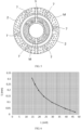
- one or more winding coils may be selected very conveniently and arranged in a circumferential direction of the fixed part 1.
- four or six winding coils may be evenly arranged in the circumferential direction of the fixed part 1 at the same time, which not only helps promote outwardly providing and applying the electromagnetic force more evenly, but also provides a certain degree of redundancy at the same time, thereby improving the safety and reliability of the elevator brake.
- a sinusoidal wave electrical signal particularly a sinusoidal wave pulse width modulation (PWM) electrical signal may be selected for use.
- PWM sinusoidal wave pulse width modulation
- the electromagnetic member 3 it can be realized in various ways, such as by providing a corresponding PWM control module in a control part (such as an elevator frequency converter or an additional control circuit board and other software and hardware) for controlling the operation of the elevator brake in the elevator brake or in the elevator system, or by adding a circuit board with a PWM control function, etc.
- step S12 a present inductance value of the electromagnetic member 3 under the electromagnetic field M may be obtained, which will then be used to evaluate a present actual condition of the air gap S between the fixed part 1 and the moving part 2, so as to judge and analyze the present wear condition of elevator brake.
- step S12 the following formula may be used to quickly calculate the present inductance value of the electromagnetic member 3:
- L U/I ⁇ R / 2 ⁇ * f
- U and I are the present voltage and current of the electromagnetic member, respectively
- R is the resistance of the electromagnetic member itself
- f is the frequency of the above electric signal input to the electromagnetic member. All the above data can be easily obtained.
- the present voltage and current of the electromagnetic member they are used as the operating data of elevator devices, and can be directly obtained from the existing elevator brakes or control units, modules, devices or an operation management system in the elevator system.
- components such as an inductance sensor may also be equipped for the elevator brake, which is arranged at a suitable position in the elevator brake to directly collect and obtain the present inductance value of the electromagnetic member.
- the present inductance value of the electromagnetic member may also be calculated through a complex function relationship between the brake voltage and the brake current of the elevator brake; or changes in the amplitude margin and phase margin of the Bode diagram of the brake transfer function can be used to reflect the change in the present inductance of the electromagnetic member, and in this way, the degree of wear of the elevator brake can also be judged.
- the present voltage, present current and other data of the electromagnetic member can also be collected by providing corresponding sensors and detectors in the elevator brake.
- step S 13 the inductance value of the electromagnetic member obtained in step S12 can be used to obtain the value of the air gap S corresponding to it, and to evaluate the present wear condition of the friction member based on the value of the air gap S.
- the above process can be performed with the help of a standard curve model of the correspondence between the inductance of the electromagnetic member and the air gap exemplarily shown in FIG. 6 , that is, the corresponding value of the air gap S can be correspondingly obtained by searching according to a specific value of the inductance L.
- multiple sets of data on the correspondence between the inductance of the electromagnetic member and the air gap S in the first state can be obtained through testing; for example, data testing may be performed based on multiple elevator brakes of the same model and with different wear conditions, so that such a correspondence model can be provided in advance for evaluation and use in step S13.
- the above correspondence model may be constructed by self-measurement of data on site at the elevator device, or it may be directly obtained for example from manufacturers of elevator brakes or elevators, R&D institutions, equipment maintenance units, etc.
- the above correspondence model may be stored in advance in any suitable component, unit, module or device in the elevator brake or elevator system. It may take various feasible forms such as charts, data fields, texts, etc., in order to be able to better meet the needs of a variety of different applications.
- the inductance data of the electromagnetic member under the electromagnetic field can be used to determine the wear condition of the friction member. It should also be pointed out that the method of the present disclosure also allows for the analysis and processing of the wear condition of the friction member based on inductance response data of the electromagnetic member under the electromagnetic field.
- the inductance response data generally refers to physical characteristic data of the electromagnetic member after the response to the influence of the inductance characteristic under the electromagnetic field, such as current data. Specifically, when the electromagnetic member in the elevator brake is energized to generate an electromagnetic field, physical characteristics such as an operating current of the electromagnetic member will respond to the inductance characteristic of the electromagnetic member formed at this time, which will be reflected in specific data.
- the wear condition of the friction member can also be determined. For example, the change of one or more current characteristics (such as current amplitude, current phase, etc.) can be judged from the current data of the electromagnetic member, and then the wear condition of the friction member can be analyzed and determined, such as whether the decrease of the current amplitude is within a preset range, whether the offset of the current phase meets expectation and whether it is within a preset range, etc.
- the change of one or more current characteristics such as current amplitude, current phase, etc.
- the present wear condition of the friction member in the elevator brake can be learned timely, accurately and quickly; in particular, it is no longer necessary to arrange technicians to go to the device installation place of the elevator brake for on-site measurement. Since various types of elevator devices have been widely used in modern society, and the number of installations is quite large, the application of the solutions of the present disclosure can greatly reduce the large amount of labor and time costs currently invested in wear detection of each elevator brake, significantly reduce device maintenance costs, and help find device problems in time to actively and effectively take countermeasures, thereby enhancing the safety performance and service level of the elevator system.
- a step of confirming whether the elevator car is currently in a stopped and empty state may be further added before the above step S11, that is, only after it is determined that the elevator car is suitable for the detection operation, will steps S11-S13 be executed, which helps enhance the safety of the entire detection operation.
- report information related the obtained present wear condition of the elevator brake may be output outwardly; for example, such report information can be stored locally in the elevator or stored in a cloud server, so that elevator operation management personnel, equipment maintenance personnel, equipment manufacturers or parts suppliers can be informed in time. It can be understood that those skilled in the art can make flexible settings on the specific content, expression form, transmission path, level, etc., of the report information according to actual requirements.
- the report information may be sent to the user end (such as a mobile phone, a PAD and other mobile communication terminals) in the form of text prompts, voice reminders, etc., so as to enable the user to grasp the present wear condition of the elevator brake in time. Therefore, preventive measures such as purchasing spare parts (e.g., the friction member) in advance ensure that the elevator system can operate safely and reliably for a long time.
- the user end such as a mobile phone, a PAD and other mobile communication terminals
- preventive measures such as purchasing spare parts (e.g., the friction member) in advance ensure that the elevator system can operate safely and reliably for a long time.
- the elevator may be controlled to stop running, and the report information may be sent to the user end, etc., so as to achieve the effects of safety precautions and timely warning.
- the method of the present disclosure may be implemented as required; it may be performed in a one-time manner at any suitable time point, or may be implemented automatically with a preset time cycle (such as once every five days, once a week, once every two weeks, etc.).
- the operating time of the elevator may be divided into a busy period (such as daytime working periods on working days) and an idle period (such as midnight periods on working days (such as 00:00-3:00, 01:00-2:00, etc.), or midnight periods on only non-working days), and then the method of the present disclosure is automatically performed only in the above idle period with a preset time cycle, so as to automatically track and grasp the wear condition of the elevator brake during the whole process, which will not cause any adverse effect on the normal operation and use of the elevator.
- a busy period such as daytime working periods on working days
- an idle period such as midnight periods on working days (such as 00:00-3:00, 01:00-2:00, etc.), or midnight periods on only non-working days)
- the present disclosure also provides an elevator brake wear detection device, which is provided with a controller for executing corresponding steps of the method according to the present disclosure discussed above for example.
- the elevator brake wear detection device can be manufactured and sold separately.
- an elevator brake is also provided.
- the elevator brake may be equipped with the elevator brake wear detection device designed and provided according to the present disclosure, which can automatically, conveniently, efficiently and accurately detect the wear condition of the elevator brake, and significantly reduce elevator maintenance cost, so as to achieve these significant technical advantages as mentioned above. Therefore, the present invention has very high practical value and creates considerable economic benefits.
Landscapes
- Engineering & Computer Science (AREA)
- Automation & Control Theory (AREA)
- Mechanical Engineering (AREA)
- Braking Arrangements (AREA)
- Cage And Drive Apparatuses For Elevators (AREA)
- Maintenance And Inspection Apparatuses For Elevators (AREA)
Claims (15)
- Verfahren zur Erkennung von Aufzugsbremsenverschleiß, wobei die Aufzugsbremse (10) ein ortsfestes Teil (1) mit einem elektromagnetischen Element (3) und ein bewegliches Teil (2) mit einem Reibungselement (4) umfasst; wobei die Aufzugsbremse (10) das bewegliche Teil (2) in einem ersten Zustand antreibt, sich in Richtung einer Aufzugsleistungsvorrichtung (20) zu bewegen und die Aufzugsleistungsvorrichtung (20) durch das Reibungselement (4) zu berühren, um eine Bremskraft (F1) zum Anhalten einer Aufzugskabine (200) bereitzustellen, und die Aufzugsbremse (10) in einem zweiten Zustand eine elektromagnetische Kraft (F2) durch das elektromagnetische Element (3) bereitstellt, um den Kontakt des Reibungselements (4) mit der Aufzugsleistungsvorrichtung (20) zu lösen, und wobei das Verfahren zur Erkennung von Aufzugsbremsenverschleiß (10) folgenden Schritt umfasst:A. Versetzen der Aufzugsbremse (10) in den ersten Zustand und Eingeben eines elektrischen Signals zum Erzeugen eines elektromagnetischen Felds (M), das durch einen Luftspalt (S) zwischen dem ortsfesten Teil (1) und dem beweglichen Teil (2) verläuft, in das elektromagnetische Element (3);und dadurch gekennzeichnet, dass es die folgenden weiteren Schritte umfasst:B. Erhalten von Daten zur Induktivität (L) oder Antwortdaten zur Induktivität (L) des elektromagnetischen Elements (3) unter dem elektromagnetischen Feld (M); undC. basierend auf einem voreingestellten Korrespondenzmodell zwischen der Induktivität (L) des elektromagnetischen Elements (3) und dem Luftspalt (S) in dem ersten Zustand Erhalten eines entsprechenden Werts für den Luftspalt (S) gemäß den Daten zur Induktivität (L), um einen Verschleißzustand des Reibungselements (4) zu bestimmen, oder Bestimmen des Verschleißzustands des Reibungselements (4) gemäß den Antwortdaten zur Induktivität (L).
- Verfahren zur Erkennung von Aufzugsbremsenverschleiß nach Anspruch 1, wobei das elektromagnetische Element (3) in Schritt A eine oder mehrere Wicklungsspulen ist, die in Umfangsrichtung des ortsfesten Teils (1) angeordnet sind, und das elektrische Signal ein in die Wicklungsspule eingegebenes, pulsbreitenmoduliertes elektrisches Signal mit sinusförmiger Welle ist.
- Verfahren zur Erkennung von Aufzugsbremsenverschleiß nach einem der vorhergehenden Ansprüche, wobei die Daten zur Induktivität (L) in Schritt B gemäß der folgenden Formel berechnet werden:

- Verfahren zur Erkennung von Aufzugsbremsenverschleiß nach einem der vorhergehenden Ansprüche, wobei das Korrespondenzmodell in Schritt C ein Standardkurvenmodell ist, das basierend auf den durch Erkennung erhaltenen entsprechenden Daten der Induktivität des elektromagnetischen Elements (3) und des Luftspalts (S) in dem ersten Zustand erstellt wird; oder die Antwortdaten zur Induktivität (L) Stromdaten des elektromagnetischen Elements (3) umfassen, wobei eine Änderung von mindestens einer Stromkennlinie gemäß den Stromdaten beurteilt wird, um den Verschleißzustand des Reibungselements (4) zu bestimmen, und die Stromkennlinien Stromamplitude und Stromphase umfassen.
- Verfahren zur Erkennung von Aufzugsbremsenverschleiß nach einem der vorhergehenden Ansprüche, ferner umfassend die folgenden Schritte:Bestätigen vor Ausführen von Schritt A, dass sich die Aufzugskabine (200) aktuell in einem angehaltenen und leeren Zustand befindet; und/oderAusgeben von Berichtsinformationen betreffend den Verschleißzustand des Reibelements (4) nach Ausführen von Schritt C; undoptionalwobei die Berichtsinformationen lokal in dem Aufzug gespeichert oder auf einem Cloud-Server gespeichert werden.
- Verfahren zur Erkennung von Aufzugsbremsenverschleiß nach Anspruch 5, wobei die Berichtsinformationen an ein Benutzerende gesendet werden, das ein mobiles Kommunikationsendgerät des Benutzers umfasst, wenn der erhaltene Wert für den Luftspalt (S) einen ersten voreingestellten Wert überschreitet; und/oder der Aufzug gesteuert wird anzuhalten und/oder die Berichtsinformationen an das Benutzerende gesendet werden, wenn der erhaltene Wert für den Luftspalt (S) einen zweiten voreingestellten Wert überschreitet, wobei der zweite voreingestellte Wert größer ist als der erste voreingestellte Wert.
- Verfahren zur Erkennung von Aufzugsbremsenverschleiß nach einem der vorhergehenden Ansprüche, wobei eine Betriebszeit des Aufzugs eine Stillstandszeit und eine Arbeitszeit umfasst und Schritt A-C in der Stillstandszeit mit einem voreingestellten Zeitzyklus automatisch ausgeführt werden.
- Vorrichtung zur Erkennung von Aufzugsbremsenverschleiß, wobei die Aufzugsbremse (10) ein ortsfestes Teil (1) mit einem elektromagnetischen Element (3) und ein bewegliches Teil (2) mit einem Reibungselement (4) umfasst; wobei die Aufzugsbremse (10) das bewegliche Teil (2) in einem ersten Zustand antreibt, sich in Richtung einer Aufzugsleistungsvorrichtung (20) zu bewegen und die Aufzugsleistungsvorrichtung (20) durch das Reibungselement (4) zu berühren, um eine Bremskraft (F1) zum Anhalten einer Aufzugskabine (200) bereitzustellen, und die Aufzugsbremse (10) in einem zweiten Zustand eine elektromagnetische Kraft (F2) durch das elektromagnetische Element (3) bereitstellt, um den Kontakt des Reibungselements (4) mit der Aufzugsleistungsvorrichtung (20) zu lösen, wobei die Vorrichtung zur Erkennung von Aufzugsbremsenverschleiß eine Steuerung umfasst, die zum Ausführen des folgenden Schritts konfiguriert ist:A. Versetzen der Aufzugsbremse (10) in den ersten Zustand und Eingeben eines elektrischen Signals zum Erzeugen eines elektromagnetischen Felds (M), das durch einen Luftspalt (S) zwischen dem ortsfesten Teil (1) und dem beweglichen Teil (2) verläuft, in das elektromagnetische Element (3);und dadurch gekennzeichnet, dass die Steuereinheit ferner zum Ausführen der folgenden Schritte konfiguriert ist:B. Erhalten von Daten zur Induktivität (L) oder Antwortdaten zur Induktivität (L) des elektromagnetischen Elements (3) unter dem elektromagnetischen Feld (M); undC. basierend auf einem voreingestellten Korrespondenzmodell zwischen der Induktivität (L) des elektromagnetischen Elements (3) und dem Luftspalt (S) in dem ersten Zustand Erhalten eines entsprechenden Werts für den Luftspalt (S) gemäß den Daten zur Induktivität (L), um einen Verschleißzustand des Reibungselements (4) zu bestimmen, oder Bestimmen des Verschleißzustands des Reibungselements (4) gemäß den Antwortdaten zur Induktivität (L).
- Vorrichtung zur Erkennung von Aufzugsbremsenverschleiß nach Anspruch 8, wobei das elektromagnetische Element (3) eine oder mehrere Wicklungsspulen ist, die in Umfangsrichtung des ortsfesten Teils (1) angeordnet sind, und das elektrische Signal ein in die Wicklungsspule eingegebenes, pulsbreitenmoduliertes elektrisches Signal mit sinusförmiger Welle ist.
- Vorrichtung zur Erkennung von Aufzugsbremsenverschleiß nach einem der Ansprüche 8 oder 9, wobei die Steuerung zum Berechnen der Daten zur Induktivität (L) gemäß der folgenden Formel konfiguriert ist:

- Vorrichtung zur Erkennung von Aufzugsbremsenverschleiß nach einem der Ansprüche 8-10, wobei das Korrespondenzmodell ein Standardkurvenmodell ist, das basierend auf den durch Erkennung erhaltenen entsprechenden Daten der Induktivität (L) des elektromagnetischen Elements (3) und des Luftspalts (S) in dem ersten Zustand erstellt wird; oder die Antwortdaten zur Induktivität (L) Stromdaten des elektromagnetischen Elements (3) umfassen, wobei eine Änderung von mindestens einer Stromkennlinie gemäß den Stromdaten beurteilt wird, um den Verschleißzustand des Reibungselements (4) zu bestimmen, und die Stromkennlinien Stromamplitude und Stromphase umfassen.
- Vorrichtung zur Erkennung von Aufzugsbremsenverschleiß nach einem der Ansprüche 8-11, wobei die Steuerung ferner zum Ausführen der folgenden Schritte konfiguriert ist:Bestätigen vor Ausführen von Schritt A, dass sich die Aufzugskabine (200) aktuell in einem angehaltenen und leeren Zustand befindet; und/oderAusgeben von Berichtsinformationen betreffend den Verschleißzustand des Reibelements (4) nach Ausführen von Schritt C; undoptionalwobei die Berichtsinformationen lokal in dem Aufzug gespeichert oder auf einem Cloud-Server gespeichert werden.
- Vorrichtung zur Erkennung von Aufzugsbremsenverschleiß nach Anspruch 12, wobei die Steuerung ferner zu Folgendem konfiguriert ist:Senden der Berichtsinformationen an ein Benutzerende, das ein mobiles Kommunikationsendgerät des Benutzers umfasst, wenn der erhaltene Wert für den Luftspalt (S) einen ersten voreingestellten Wert überschreitet; und/oderSteuern des Aufzugs anzuhalten und/oder Senden der Berichtsinformationen an das Benutzerende, wenn der erhaltene Wert für den Luftspalt (S) einen zweiten voreingestellten Wert überschreitet, wobei der zweite voreingestellte Wert größer ist als der erste voreingestellte Wert.
- Vorrichtung zur Erkennung von Aufzugsbremsenverschleiß nach einem der Ansprüche 8-13, wobei eine Betriebszeit des Aufzugs eine Stillstandszeit und eine Arbeitszeit umfasst und die Steuerung zum automatischen Ausführen von Schritt A-C in der Stillstandszeit mit einem voreingestellten Zeitzyklus konfiguriert ist.
- Aufzugsbremse (10), die mit der Vorrichtung zur Erkennung von Aufzugsbremsenverschleiß nach einem der Ansprüche 8 bis 14 bereitgestellt ist.
Applications Claiming Priority (1)
| Application Number | Priority Date | Filing Date | Title |
|---|---|---|---|
| CN202110251008.5A CN115043283A (zh) | 2021-03-08 | 2021-03-08 | 电梯制动器磨损检测方法和检测装置以及电梯制动器 |
Publications (2)
| Publication Number | Publication Date |
|---|---|
| EP4056510A1 EP4056510A1 (de) | 2022-09-14 |
| EP4056510B1 true EP4056510B1 (de) | 2025-01-29 |
Family
ID=78829365
Family Applications (1)
| Application Number | Title | Priority Date | Filing Date |
|---|---|---|---|
| EP21213816.8A Active EP4056510B1 (de) | 2021-03-08 | 2021-12-10 | Verfahren zur erkennung von aufzugsbremsenverschleiss, erkennungsvorrichtung und aufzugsbremse |
Country Status (4)
| Country | Link |
|---|---|
| US (1) | US20220281717A1 (de) |
| EP (1) | EP4056510B1 (de) |
| CN (1) | CN115043283A (de) |
| ES (1) | ES3010211T3 (de) |
Families Citing this family (3)
| Publication number | Priority date | Publication date | Assignee | Title |
|---|---|---|---|---|
| CN117142287A (zh) * | 2022-05-24 | 2023-12-01 | 奥的斯电梯公司 | 用于制动装置的自检测装置和方法及电梯系统 |
| CN115594049B (zh) * | 2022-12-01 | 2023-03-10 | 苏州通润驱动设备股份有限公司 | 一种盘式制动器中摩擦盘的花键齿的磨损检测方法 |
| CN120039242B (zh) * | 2025-04-03 | 2025-09-26 | 湖北域控智驱科技有限公司 | 一种提高制动精度的emb系统主动校准方法及装置 |
Family Cites Families (5)
| Publication number | Priority date | Publication date | Assignee | Title |
|---|---|---|---|---|
| US4984659A (en) * | 1988-02-01 | 1991-01-15 | Mitsubishi Denki Kabushiki Kaisha | Elevator control apparatus |
| SG10201710621UA (en) * | 2013-06-21 | 2018-02-27 | Inventio Ag | Elevator brake force and distance sensor |
| CN108799373B (zh) * | 2017-05-04 | 2024-08-20 | 蒂升电梯(上海)有限公司 | 用于检测电磁制动器的制动片磨损的检测装置及电梯 |
| EP3587325A1 (de) * | 2018-06-29 | 2020-01-01 | KONE Corporation | Verfahren zur diagnose und/oder wartung einer bremse eines transportsystems, softwareprogramm und bremsvorrichtung |
| ES2902592T3 (es) * | 2018-10-05 | 2022-03-29 | Chr Mayr Gmbh Co Kg | Control de funcionamiento preventivo en un freno a presión de muelle electromagnético |
-
2021
- 2021-03-08 CN CN202110251008.5A patent/CN115043283A/zh active Pending
- 2021-11-09 US US17/522,357 patent/US20220281717A1/en active Pending
- 2021-12-10 ES ES21213816T patent/ES3010211T3/es active Active
- 2021-12-10 EP EP21213816.8A patent/EP4056510B1/de active Active
Also Published As
| Publication number | Publication date |
|---|---|
| CN115043283A (zh) | 2022-09-13 |
| EP4056510A1 (de) | 2022-09-14 |
| ES3010211T3 (en) | 2025-04-01 |
| US20220281717A1 (en) | 2022-09-08 |
Similar Documents
| Publication | Publication Date | Title |
|---|---|---|
| EP4056510A1 (de) | Verfahren zur erkennung von aufzugsbremsenverschleiss, erkennungsvorrichtung und aufzugsbremse | |
| US9809419B2 (en) | Elevator apparatus | |
| EP2773584B1 (de) | Bremsdrehmomentüberwachung und gesundheitsbewertung | |
| EP2266910B1 (de) | Aufzugsanlage | |
| CN104909234B (zh) | 对垂直传送设备机械制动器的工作状况检测的方法和装置 | |
| CN101023016B (zh) | 用于确定运动物体的运动状态的信号带和系统 | |
| CN112225028B (zh) | 一种电流感应的电梯运行数据采集系统及其采集方法 | |
| CN108861923B (zh) | 自动电梯检查系统和方法 | |
| CN105270953B (zh) | 电梯装置的控制装置和电梯装置 | |
| KR101731281B1 (ko) | 리타더의 내구 및 성능 검증을 위한 평가 시스템 및 그 평가방법 | |
| CN109516331A (zh) | 用于电梯的安全制动系统 | |
| CN108059048A (zh) | 一种电梯制动器的检测预警系统及预警方法 | |
| KR20210055762A (ko) | 엘리베이터의 브레이크 장치 이상 진단 시스템 | |
| CN105527083A (zh) | 一种电梯限速器动作速度校验仪器及方法 | |
| CN104555643A (zh) | 停运条件检测 | |
| CA2545146C (en) | Failure detecting device for elevator drive power source and failure detecting method for elevator drive power source | |
| CN106225983B (zh) | 制动器制动力矩的在线检测方法及装置 | |
| CN111824884A (zh) | 制动衬片监测系统 | |
| WO2020147710A1 (zh) | 电梯故障诊断方法、装置、设备和介质 | |
| JP2004123270A (ja) | エレベータ用電磁ブレーキの異常診断装置 | |
| EP3889571B1 (de) | Verfahren und system zur diagnose einer drehmaschine | |
| JP3639080B2 (ja) | エレベータのブレーキ特性評価装置 | |
| EP4015431B1 (de) | Ein selbstprüfungsverfahren für eine aufzugsbremssvorrichtung | |
| CN109631800B (zh) | 一种接触线动态抬升量检测方法及装置 | |
| CN118701918A (zh) | 一种自动扶梯智能远程在线故障监测系统 |
Legal Events
| Date | Code | Title | Description |
|---|---|---|---|
| PUAI | Public reference made under article 153(3) epc to a published international application that has entered the european phase |
Free format text: ORIGINAL CODE: 0009012 |
|
| STAA | Information on the status of an ep patent application or granted ep patent |
Free format text: STATUS: THE APPLICATION HAS BEEN PUBLISHED |
|
| AK | Designated contracting states |
Kind code of ref document: A1 Designated state(s): AL AT BE BG CH CY CZ DE DK EE ES FI FR GB GR HR HU IE IS IT LI LT LU LV MC MK MT NL NO PL PT RO RS SE SI SK SM TR |
|
| STAA | Information on the status of an ep patent application or granted ep patent |
Free format text: STATUS: REQUEST FOR EXAMINATION WAS MADE |
|
| 17P | Request for examination filed |
Effective date: 20230314 |
|
| RBV | Designated contracting states (corrected) |
Designated state(s): AL AT BE BG CH CY CZ DE DK EE ES FI FR GB GR HR HU IE IS IT LI LT LU LV MC MK MT NL NO PL PT RO RS SE SI SK SM TR |
|
| GRAP | Despatch of communication of intention to grant a patent |
Free format text: ORIGINAL CODE: EPIDOSNIGR1 |
|
| STAA | Information on the status of an ep patent application or granted ep patent |
Free format text: STATUS: GRANT OF PATENT IS INTENDED |
|
| RIC1 | Information provided on ipc code assigned before grant |
Ipc: B66B 5/18 20060101ALN20240815BHEP Ipc: B66B 1/32 20060101ALI20240815BHEP Ipc: B66B 5/00 20060101AFI20240815BHEP |
|
| INTG | Intention to grant announced |
Effective date: 20240912 |
|
| GRAS | Grant fee paid |
Free format text: ORIGINAL CODE: EPIDOSNIGR3 |
|
| GRAA | (expected) grant |
Free format text: ORIGINAL CODE: 0009210 |
|
| STAA | Information on the status of an ep patent application or granted ep patent |
Free format text: STATUS: THE PATENT HAS BEEN GRANTED |
|
| AK | Designated contracting states |
Kind code of ref document: B1 Designated state(s): AL AT BE BG CH CY CZ DE DK EE ES FI FR GB GR HR HU IE IS IT LI LT LU LV MC MK MT NL NO PL PT RO RS SE SI SK SM TR |
|
| REG | Reference to a national code |
Ref country code: GB Ref legal event code: FG4D |
|
| REG | Reference to a national code |
Ref country code: CH Ref legal event code: EP |
|
| REG | Reference to a national code |
Ref country code: DE Ref legal event code: R096 Ref document number: 602021025343 Country of ref document: DE |
|
| REG | Reference to a national code |
Ref country code: IE Ref legal event code: FG4D |
|
| REG | Reference to a national code |
Ref country code: ES Ref legal event code: FG2A Ref document number: 3010211 Country of ref document: ES Kind code of ref document: T3 Effective date: 20250401 |
|
| REG | Reference to a national code |
Ref country code: NL Ref legal event code: MP Effective date: 20250129 |
|
| PG25 | Lapsed in a contracting state [announced via postgrant information from national office to epo] |
Ref country code: NL Free format text: LAPSE BECAUSE OF FAILURE TO SUBMIT A TRANSLATION OF THE DESCRIPTION OR TO PAY THE FEE WITHIN THE PRESCRIBED TIME-LIMIT Effective date: 20250129 |
|
| PG25 | Lapsed in a contracting state [announced via postgrant information from national office to epo] |
Ref country code: RS Free format text: LAPSE BECAUSE OF FAILURE TO SUBMIT A TRANSLATION OF THE DESCRIPTION OR TO PAY THE FEE WITHIN THE PRESCRIBED TIME-LIMIT Effective date: 20250429 |
|
| PG25 | Lapsed in a contracting state [announced via postgrant information from national office to epo] |
Ref country code: FI Free format text: LAPSE BECAUSE OF FAILURE TO SUBMIT A TRANSLATION OF THE DESCRIPTION OR TO PAY THE FEE WITHIN THE PRESCRIBED TIME-LIMIT Effective date: 20250129 |
|
| PG25 | Lapsed in a contracting state [announced via postgrant information from national office to epo] |
Ref country code: PL Free format text: LAPSE BECAUSE OF FAILURE TO SUBMIT A TRANSLATION OF THE DESCRIPTION OR TO PAY THE FEE WITHIN THE PRESCRIBED TIME-LIMIT Effective date: 20250129 |
|
| REG | Reference to a national code |
Ref country code: LT Ref legal event code: MG9D |
|
| PG25 | Lapsed in a contracting state [announced via postgrant information from national office to epo] |
Ref country code: NO Free format text: LAPSE BECAUSE OF FAILURE TO SUBMIT A TRANSLATION OF THE DESCRIPTION OR TO PAY THE FEE WITHIN THE PRESCRIBED TIME-LIMIT Effective date: 20250429 Ref country code: IS Free format text: LAPSE BECAUSE OF FAILURE TO SUBMIT A TRANSLATION OF THE DESCRIPTION OR TO PAY THE FEE WITHIN THE PRESCRIBED TIME-LIMIT Effective date: 20250529 |
|
| REG | Reference to a national code |
Ref country code: AT Ref legal event code: MK05 Ref document number: 1763310 Country of ref document: AT Kind code of ref document: T Effective date: 20250129 |
|
| PG25 | Lapsed in a contracting state [announced via postgrant information from national office to epo] |
Ref country code: HR Free format text: LAPSE BECAUSE OF FAILURE TO SUBMIT A TRANSLATION OF THE DESCRIPTION OR TO PAY THE FEE WITHIN THE PRESCRIBED TIME-LIMIT Effective date: 20250129 |
|
| PG25 | Lapsed in a contracting state [announced via postgrant information from national office to epo] |
Ref country code: LV Free format text: LAPSE BECAUSE OF FAILURE TO SUBMIT A TRANSLATION OF THE DESCRIPTION OR TO PAY THE FEE WITHIN THE PRESCRIBED TIME-LIMIT Effective date: 20250129 Ref country code: PT Free format text: LAPSE BECAUSE OF FAILURE TO SUBMIT A TRANSLATION OF THE DESCRIPTION OR TO PAY THE FEE WITHIN THE PRESCRIBED TIME-LIMIT Effective date: 20250529 |
|
| PG25 | Lapsed in a contracting state [announced via postgrant information from national office to epo] |
Ref country code: BG Free format text: LAPSE BECAUSE OF FAILURE TO SUBMIT A TRANSLATION OF THE DESCRIPTION OR TO PAY THE FEE WITHIN THE PRESCRIBED TIME-LIMIT Effective date: 20250129 Ref country code: GR Free format text: LAPSE BECAUSE OF FAILURE TO SUBMIT A TRANSLATION OF THE DESCRIPTION OR TO PAY THE FEE WITHIN THE PRESCRIBED TIME-LIMIT Effective date: 20250430 |
|
| PG25 | Lapsed in a contracting state [announced via postgrant information from national office to epo] |
Ref country code: AT Free format text: LAPSE BECAUSE OF FAILURE TO SUBMIT A TRANSLATION OF THE DESCRIPTION OR TO PAY THE FEE WITHIN THE PRESCRIBED TIME-LIMIT Effective date: 20250129 |
|
| PG25 | Lapsed in a contracting state [announced via postgrant information from national office to epo] |
Ref country code: SE Free format text: LAPSE BECAUSE OF FAILURE TO SUBMIT A TRANSLATION OF THE DESCRIPTION OR TO PAY THE FEE WITHIN THE PRESCRIBED TIME-LIMIT Effective date: 20250129 |
|
| PG25 | Lapsed in a contracting state [announced via postgrant information from national office to epo] |
Ref country code: SM Free format text: LAPSE BECAUSE OF FAILURE TO SUBMIT A TRANSLATION OF THE DESCRIPTION OR TO PAY THE FEE WITHIN THE PRESCRIBED TIME-LIMIT Effective date: 20250129 |
|
| PG25 | Lapsed in a contracting state [announced via postgrant information from national office to epo] |
Ref country code: DK Free format text: LAPSE BECAUSE OF FAILURE TO SUBMIT A TRANSLATION OF THE DESCRIPTION OR TO PAY THE FEE WITHIN THE PRESCRIBED TIME-LIMIT Effective date: 20250129 |
|
| PG25 | Lapsed in a contracting state [announced via postgrant information from national office to epo] |
Ref country code: IT Free format text: LAPSE BECAUSE OF FAILURE TO SUBMIT A TRANSLATION OF THE DESCRIPTION OR TO PAY THE FEE WITHIN THE PRESCRIBED TIME-LIMIT Effective date: 20250129 |
|
| PG25 | Lapsed in a contracting state [announced via postgrant information from national office to epo] |
Ref country code: EE Free format text: LAPSE BECAUSE OF FAILURE TO SUBMIT A TRANSLATION OF THE DESCRIPTION OR TO PAY THE FEE WITHIN THE PRESCRIBED TIME-LIMIT Effective date: 20250129 Ref country code: CZ Free format text: LAPSE BECAUSE OF FAILURE TO SUBMIT A TRANSLATION OF THE DESCRIPTION OR TO PAY THE FEE WITHIN THE PRESCRIBED TIME-LIMIT Effective date: 20250129 |
|
| PG25 | Lapsed in a contracting state [announced via postgrant information from national office to epo] |
Ref country code: RO Free format text: LAPSE BECAUSE OF FAILURE TO SUBMIT A TRANSLATION OF THE DESCRIPTION OR TO PAY THE FEE WITHIN THE PRESCRIBED TIME-LIMIT Effective date: 20250129 |
|
| PG25 | Lapsed in a contracting state [announced via postgrant information from national office to epo] |
Ref country code: SK Free format text: LAPSE BECAUSE OF FAILURE TO SUBMIT A TRANSLATION OF THE DESCRIPTION OR TO PAY THE FEE WITHIN THE PRESCRIBED TIME-LIMIT Effective date: 20250129 |
|
| REG | Reference to a national code |
Ref country code: DE Ref legal event code: R097 Ref document number: 602021025343 Country of ref document: DE |
|
| PLBE | No opposition filed within time limit |
Free format text: ORIGINAL CODE: 0009261 |
|
| STAA | Information on the status of an ep patent application or granted ep patent |
Free format text: STATUS: NO OPPOSITION FILED WITHIN TIME LIMIT |
|
| 26N | No opposition filed |
Effective date: 20251030 |
|
| PGFP | Annual fee paid to national office [announced via postgrant information from national office to epo] |
Ref country code: DE Payment date: 20251126 Year of fee payment: 5 |
|
| PGFP | Annual fee paid to national office [announced via postgrant information from national office to epo] |
Ref country code: FR Payment date: 20251120 Year of fee payment: 5 |
|
| PGFP | Annual fee paid to national office [announced via postgrant information from national office to epo] |
Ref country code: ES Payment date: 20260102 Year of fee payment: 5 |