EP4056293A1 - Verfahren und anlage zur herstellung von flachwalzprodukten - Google Patents
Verfahren und anlage zur herstellung von flachwalzprodukten Download PDFInfo
- Publication number
- EP4056293A1 EP4056293A1 EP21172611.2A EP21172611A EP4056293A1 EP 4056293 A1 EP4056293 A1 EP 4056293A1 EP 21172611 A EP21172611 A EP 21172611A EP 4056293 A1 EP4056293 A1 EP 4056293A1
- Authority
- EP
- European Patent Office
- Prior art keywords
- strip
- profile
- crown
- work rolls
- work
- Prior art date
- Legal status (The legal status is an assumption and is not a legal conclusion. Google has not performed a legal analysis and makes no representation as to the accuracy of the status listed.)
- Granted
Links
Images


Classifications
-
- B—PERFORMING OPERATIONS; TRANSPORTING
- B21—MECHANICAL METAL-WORKING WITHOUT ESSENTIALLY REMOVING MATERIAL; PUNCHING METAL
- B21B—ROLLING OF METAL
- B21B13/00—Metal-rolling stands, i.e. an assembly composed of a stand frame, rolls, and accessories
- B21B13/02—Metal-rolling stands, i.e. an assembly composed of a stand frame, rolls, and accessories with axes of rolls arranged horizontally
-
- B—PERFORMING OPERATIONS; TRANSPORTING
- B21—MECHANICAL METAL-WORKING WITHOUT ESSENTIALLY REMOVING MATERIAL; PUNCHING METAL
- B21B—ROLLING OF METAL
- B21B1/00—Metal-rolling methods or mills for making semi-finished products of solid or profiled cross-section; Sequence of operations in milling trains; Layout of rolling-mill plant, e.g. grouping of stands; Succession of passes or of sectional pass alternations
- B21B1/22—Metal-rolling methods or mills for making semi-finished products of solid or profiled cross-section; Sequence of operations in milling trains; Layout of rolling-mill plant, e.g. grouping of stands; Succession of passes or of sectional pass alternations for rolling plates, strips, bands or sheets of indefinite length
- B21B1/24—Metal-rolling methods or mills for making semi-finished products of solid or profiled cross-section; Sequence of operations in milling trains; Layout of rolling-mill plant, e.g. grouping of stands; Succession of passes or of sectional pass alternations for rolling plates, strips, bands or sheets of indefinite length in a continuous or semi-continuous process
- B21B1/26—Metal-rolling methods or mills for making semi-finished products of solid or profiled cross-section; Sequence of operations in milling trains; Layout of rolling-mill plant, e.g. grouping of stands; Succession of passes or of sectional pass alternations for rolling plates, strips, bands or sheets of indefinite length in a continuous or semi-continuous process by hot-rolling, e.g. Steckel hot mill
-
- B—PERFORMING OPERATIONS; TRANSPORTING
- B21—MECHANICAL METAL-WORKING WITHOUT ESSENTIALLY REMOVING MATERIAL; PUNCHING METAL
- B21B—ROLLING OF METAL
- B21B1/00—Metal-rolling methods or mills for making semi-finished products of solid or profiled cross-section; Sequence of operations in milling trains; Layout of rolling-mill plant, e.g. grouping of stands; Succession of passes or of sectional pass alternations
- B21B1/22—Metal-rolling methods or mills for making semi-finished products of solid or profiled cross-section; Sequence of operations in milling trains; Layout of rolling-mill plant, e.g. grouping of stands; Succession of passes or of sectional pass alternations for rolling plates, strips, bands or sheets of indefinite length
-
- B—PERFORMING OPERATIONS; TRANSPORTING
- B21—MECHANICAL METAL-WORKING WITHOUT ESSENTIALLY REMOVING MATERIAL; PUNCHING METAL
- B21B—ROLLING OF METAL
- B21B1/00—Metal-rolling methods or mills for making semi-finished products of solid or profiled cross-section; Sequence of operations in milling trains; Layout of rolling-mill plant, e.g. grouping of stands; Succession of passes or of sectional pass alternations
- B21B1/46—Metal-rolling methods or mills for making semi-finished products of solid or profiled cross-section; Sequence of operations in milling trains; Layout of rolling-mill plant, e.g. grouping of stands; Succession of passes or of sectional pass alternations for rolling metal immediately subsequent to continuous casting
-
- B—PERFORMING OPERATIONS; TRANSPORTING
- B21—MECHANICAL METAL-WORKING WITHOUT ESSENTIALLY REMOVING MATERIAL; PUNCHING METAL
- B21B—ROLLING OF METAL
- B21B15/00—Arrangements for performing additional metal-working operations specially combined with or arranged in, or specially adapted for use in connection with, metal-rolling mills
- B21B15/0007—Cutting or shearing the product
-
- B—PERFORMING OPERATIONS; TRANSPORTING
- B21—MECHANICAL METAL-WORKING WITHOUT ESSENTIALLY REMOVING MATERIAL; PUNCHING METAL
- B21B—ROLLING OF METAL
- B21B27/00—Rolls, roll alloys or roll fabrication; Lubricating, cooling or heating rolls while in use
- B21B27/02—Shape or construction of rolls
- B21B27/021—Rolls for sheets or strips
-
- B—PERFORMING OPERATIONS; TRANSPORTING
- B21—MECHANICAL METAL-WORKING WITHOUT ESSENTIALLY REMOVING MATERIAL; PUNCHING METAL
- B21B—ROLLING OF METAL
- B21B27/00—Rolls, roll alloys or roll fabrication; Lubricating, cooling or heating rolls while in use
- B21B27/06—Lubricating, cooling or heating rolls
- B21B27/10—Lubricating, cooling or heating rolls externally
-
- B—PERFORMING OPERATIONS; TRANSPORTING
- B21—MECHANICAL METAL-WORKING WITHOUT ESSENTIALLY REMOVING MATERIAL; PUNCHING METAL
- B21B—ROLLING OF METAL
- B21B37/00—Control devices or methods specially adapted for metal-rolling mills or the work produced thereby
- B21B37/16—Control of thickness, width, diameter or other transverse dimensions
-
- B—PERFORMING OPERATIONS; TRANSPORTING
- B21—MECHANICAL METAL-WORKING WITHOUT ESSENTIALLY REMOVING MATERIAL; PUNCHING METAL
- B21B—ROLLING OF METAL
- B21B15/00—Arrangements for performing additional metal-working operations specially combined with or arranged in, or specially adapted for use in connection with, metal-rolling mills
- B21B15/0007—Cutting or shearing the product
- B21B2015/0021—Cutting or shearing the product in the rolling direction
-
- B—PERFORMING OPERATIONS; TRANSPORTING
- B21—MECHANICAL METAL-WORKING WITHOUT ESSENTIALLY REMOVING MATERIAL; PUNCHING METAL
- B21B—ROLLING OF METAL
- B21B15/00—Arrangements for performing additional metal-working operations specially combined with or arranged in, or specially adapted for use in connection with, metal-rolling mills
- B21B2015/0057—Coiling the rolled product
-
- B—PERFORMING OPERATIONS; TRANSPORTING
- B21—MECHANICAL METAL-WORKING WITHOUT ESSENTIALLY REMOVING MATERIAL; PUNCHING METAL
- B21B—ROLLING OF METAL
- B21B27/00—Rolls, roll alloys or roll fabrication; Lubricating, cooling or heating rolls while in use
- B21B27/06—Lubricating, cooling or heating rolls
- B21B27/10—Lubricating, cooling or heating rolls externally
- B21B2027/103—Lubricating, cooling or heating rolls externally cooling externally
-
- B—PERFORMING OPERATIONS; TRANSPORTING
- B21—MECHANICAL METAL-WORKING WITHOUT ESSENTIALLY REMOVING MATERIAL; PUNCHING METAL
- B21B—ROLLING OF METAL
- B21B2267/00—Roll parameters
- B21B2267/18—Roll crown; roll profile
- B21B2267/20—Ground camber or profile
Definitions
- the present invention concerns a method for producing flat rolled products, such as strip, and the corresponding production plant.
- the invention concerns a method and a plant for obtaining strip having a final transverse profile with multiple crown and with optimal geometric characteristics in terms of profile and planarity of the strip, even in the case where the strip is subsequently divided into longitudinal portions.
- the present invention can be applied in rolling processes both hot and cold, for producing strips in any type of ferrous or non-ferrous materials.
- Rolling plants which comprise a multi-stand rolling mill, normally divided into first roughing stands and second finishing stands.
- a temperature restoration system may be present between the roughing and finishing stands.
- the rolling mill may or may not be disposed in line with a continuous casting machine that produces thin slabs, the so-called "thin slab caster”.
- These plants can be designed and configured for a substantially continuous rolling process, the so-called “endless” process, in which the cast product is rolled in a rolling mill which is located downstream of the continuous casting machine with which it is directly engaged.
- the process can also be the semi-endless type, which provides to cut the cast slab to form a plurality of coils, or the coil-to-coil type which provides to produce one coil at a time for each cut of the slab performed.
- the strip obtained in plants of this type normally has a width that can vary from 600 mm to 2500 mm depending on the intended use of the rolled material.
- the first disadvantage concerns the crown of the two half-strips.
- the dimensional quality of the product exiting from the hot rolling process has as its focal point the control of the distribution of thickness along the width of the rolled strip.
- the geometry of the thickness along the width of the rolled product is called profile.
- the main parameter that is analyzed to evaluate the profile of the rolled product is the crown.
- the crown represents the difference between the thickness in the center and the average thickness at the edges of a rolled product.
- planarity of a rolled product is defined as its ability to adhere to a theoretical plane, and consequently non-planarity is the difference between the theoretical plane and the rolled product.
- each half-strip no longer has a symmetrical crown, as can be seen in figure 2b : in fact the profile of the half-strips has a trapezoidal shape (wedge-shaped) with a different thickness at the edges on both sides.
- JP'405 provides to carry out another rolling step in another stand in order to recover the symmetry of the profile by tapering the cut edges.
- JP'405 it is problematic to carry out the longitudinal cut in an inter-stand space, and even more problematic to control the two half-strips, especially when dealing with thin thicknesses, due to the high speeds involved.
- JP'405 does not in practice allow to control the crown of the two half-strips since, in the single rolling stand, the profile of the half-strips is returned almost symmetrical simply by Hertzian pressure at the edges.
- the heating of the rolling rolls is one of the basic problems to be faced in both hot and cold rolling.
- the direct contact of the strip being rolled with the work rolls determines a thermal flow, with heat transfer to the rolls themselves, and consequent heating thereof; this entails variations both in the dimensions (diameter) and also in the profile of the rolls themselves.
- the solution that is generally used in hot rolling is to cool the work rolls from the outside with a series of nozzles installed on some ramps.
- four cooling devices are generally used: two in the exit zone and two in the entry zone. Each device consists of one or more cooling ramps.
- the heat transmitted to the rolls produces a thermal crown; an axial flow occurs since the heat, in the roll, flows from the central zone to the two sides which, not being affected by the contact of the strip, are colder.
- the result is a differentiated expansion which, generally, produces a roll profile with a quasi-parabolic shape in the central zone, while at the edges of the strip it abruptly decreases and then remains at lower values than those of the central zone.
- thermo profile of the rolls clearly affect the rolling process and, in particular, the control of thickness, profile and planarity; it is therefore the task of the system for cooling the rolls to minimize disturbances due to variations in the thermal profile, without prejudice to the fact that the temperatures of the rolls must on average reach values that vary from 50 to 80°C (depending on the material that makes up the jacket of the roll) to optimize the duration, reducing surface wear caused by thermal fatigue and friction between the strip and the roll.
- the thermal crown of the work rolls depends on the temperature distribution along the axis of the roll; this distribution varies continuously, during the rolling campaign, causing both increases and decreases in the thermal crown with variations in the work profile of the roll. This phenomenon creates disturbances on the control of the profile and planarity of the strip being rolled:
- one purpose of the invention is to provide a method, and a corresponding plant, for the production of finished thin and even ultra-thin strip, which can subsequently be divided longitudinally in such a way as to obtain 2, 3, 4 or more distinct strip portions, each portion of the strip having optimum quality in terms of profile, planarity and thickness of the cross-section.
- the purpose of the invention is also to maintain the productivity of the rolling mill unchanged, whether a strip of width equal to the maximum width is being produced, or when strips of a width smaller than said maximum width are to be produced.
- the Applicant has devised, tested and embodied the present invention to overcome the shortcomings of the state of the art and to obtain these and other purposes and advantages.
- a slab is cast at a width defined by the design parameters of the plant itself, such as the width of the mold, the sizing of the line, the productivity required, etc., and sent to a hot strip rolling mill to obtain the final required thickness.
- a hot rolled strip is further rolled in a cold rolling mill in order to obtain thinner thicknesses.
- the work rolls of the stands of the rolling mill are configured to impart to the strip a transverse profile having a number of crowns correlated to the number of longitudinal portions into which the strip has to be subsequently divided.
- the aim is to produce two or more positive crowns on the rolled strip by using work rolls with a shaped profile having two or more corresponding negative crowns.
- the invention therefore provides to use work rolls with single crown when the finished strip will be used at the width of the starting product that is fed to the rolling mill, while work rolls with double, triple, quadruple or in any case multiple crown will be used when the rolled strip has to be subsequently divided longitudinally into two, three, four or in general into a certain number of longitudinal portions of strip.
- the longitudinal division of the strip can occur along the entire length of the strip, from head to tail, in a position between the exit from the last stand and respective distinct winding units on which the individual coils of the portions of strip are formed, or it can occur along the entire length except for a segment of the head and tail of the strip immediately before the winding onto a single coil, or it can occur after removing the coil from the winding unit, for example in the destination site of the coil itself.
- At least the last stand of the rolling mill for example the last stand of the finishing mill, or the last two or three stands of the finishing mill, comprise work rolls whose contact surface with the strip has a shaped profile that is correlated and dependent on the portions of the strip that will be subsequently obtained with the longitudinal cut.
- the profile of the work rolls will have a double negative crown if the strip will be divided longitudinally into two half-strips (double crown), it will have a triple negative crown if the strip will be divided longitudinally into three portions of strip (triple crown), and so on.
- the profile of the work roll can be defined by a curve consisting of an anti-symmetric trigonometric function and a 3 rd order polynomial function.
- the amplitude "C" refers to the width of the single crown.
- the value of the crown can also be modified by varying the value ⁇ 0 of the axial movement (shifting) of the work rolls and, by varying the parameters ⁇ and C of the above formulas , the crown function of the gap between the rolls will determine a group of different curves.
- the operation of imparting to the strip a double (or triple, or quadruple, ...) crown is performed in the last stands of the finishing mill, for example in the last or in the last two or three, in the event of particularly thin thicknesses.
- the last three stands generally have work rolls with the same diameter and the same profile. Therefore, according to the invention it is convenient to make the multiple crown in the last three stands of the finishing mill.
- the invention therefore provides to produce a finished strip with multiple crown, which is subsequently divided longitudinally in such a way as to obtain multiple distinct strip portions, each with its own crown as if they were rolled individually.
- each portion of the strip has the correct crown to obtain the desired geometric and dimensional characteristics in terms of thickness, profile and flatness.
- the thermal crown of the work roll is controlled so that it follows the trend of the mechanical crown, enhancing it.
- the cooling of the work rolls is modulated in a similar manner, cooling less where the strip will be divided and cooling more in the central zones of the respective multi-strips.
- the control of the cooling system is essentially achieved through an on-line model which, at time intervals, processes a series of information on the status of the process (temperatures of the strip, rolling forces, thickness reductions, rolling speed, etc.) thus determining the thermal profile.
- the possibility of modifying the cooling efficiency on the width according to the invention allows to define, along the double or in general multiple crown rolling campaign, the optimal thermal crown, such as to maximize the profile/flatness control capacity on the portions of strip which will then have to be divided.
- FIG. 1 an example is shown of a co-rolling plant 10 for producing strips S, in which a machine 11 for casting thin slabs feeds a hot strip rolling mill 12.
- the present invention can be applied also to cold rolling mills in which a strip obtained by a previous step of the hot process is rolled.
- the starting semi-finished product is represented by a slab that can be cast in-line on the same plant (as disclosed in the embodiment of figure 1 ) or produced off-line or in another plant.
- the starting semi-finished product is represented by a coil of rolled strip previously produced in a hot rolling mill.
- the rolling rolls in order that the rolling rolls are able to impart multiple crowns to a previously hot rolled strip having a single-crown, it is preferable that the thickness of the strip is at least 2.5 mm. Below this value, it is preferable that the strip to be cold-rolled does not have a single crown profile, but has already the number of the final crowns to be obtained at the end of the cold rolling.
- the rolling rolls are shaped to follow the multicrown profile that has been already imparted to the strip in the previous hot rolling process.
- the present invention can be applied for the production of both ferrous, such as steel, and non-ferrous, such as aluminum, strips.
- the rolling mill 12 comprises a roughing unit 13 (or roughing mill), comprising in this case three stands 14a, 14b and 14c, and a finishing unit 15 (or finishing mill), comprising in this case five stands 16a, 16b, 16c, 16d and 16e.
- a roughing unit 13 or roughing mill
- a finishing unit 15 or finishing mill
- a temperature restoration system for example an induction furnace 20, which takes the slab at exit from the roughing unit 13 back to the correct rolling temperature.
- This tunnel furnace 17 allows, in a known manner, both to function as buffer in the event the rolling mill is interrupted, even temporarily, due to accidents or a planned change of the work rolls, and also to operate in semi-endless mode.
- first pendulum shears 18 Upstream of the tunnel furnace 17 there is a first pendulum shears 18, which cuts the slab to size when the plant 10 operates in coil-to-coil or semi-endless mode.
- the strip obtained is subsequently divided longitudinally (slitting), so as to obtain portions of strip having a width that is a submultiple of, or in any case smaller than, the width of the cast slab.
- the division in width of the final rolled strip can take place directly in line, at exit from the rolling mill, or in a step following the removal of the coil, for example in a different destination plant where the strips are used.
- the division downstream of the finishing mill 15, for example into two parts, can concern:
- dedicated cutting devices can be provided which longitudinally separate the strip S into two or more strip portions S1, S2 having the same or different width.
- these devices can be inserted into and extracted from the production line based on requirements.
- the present invention provides to make the profile of the work rolls 24a, 24b of at least some of the last finishing stands 16a-16e so as to determine the correct crown on each of the portions into which the strip will be divided.
- figs. 3a and 3b respectively show the cross-section of a strip S downstream of the rolling mill 12, and the sections of the two half-strips S1, S2 obtained by longitudinally cutting the strip S along the center line.
- the strip S has a "double positive crown" which is substantially symmetrical with respect to a plane of symmetry passing through the center line M, while the two half-strips S1, S2 each have their own single positive crown.
- the profile of the work rolls 24a, 24b will show a double negative crown, one for each half-strip obtained or obtainable downstream, the same is the case in the event of three, four or more divided portions of strip.
- each work roll 24a, 24b can be defined by a curve consisting of an anti-symmetric trigonometric function and a 3 rd order polynomial function.
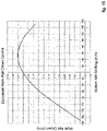
- the extent of the crown on the strip can be modified by varying the value ⁇ s of the axial movement (shifting) of the work rolls 24a, 24b, as shown in figs. 6 , 9 , 12 , 15 .
- the strip S has a width of 2000 mm, corresponding to the width of the cast slab, and is rolled with a double crown by work rolls 24a, 24b having a barrel length equal to 2450 mm, in order to be subsequently divided longitudinally into two half-strips of 1000 mm.
- work rolls 24a, 24b having a barrel length equal to 2450 mm, in order to be subsequently divided longitudinally into two half-strips of 1000 mm.
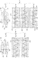
- the last finishing stand 16e (however, it could be the last two, three or more), is represented in fig. 4a and 5a as comprising upper 24a and lower 24b work rolls, and upper 25a and lower 25b support rolls.
- Figs. 4b-4c and 5b-5c represent the profile, respectively, of the upper work roll 24a and of the lower work roll 24b, in two distinct operating conditions.
- fig. 5d shows the resulting profile P(S) of the strip S as the sum of the profiles L(Tu) and L(Bu).
- the vertical end lines indicate the lateral edges of the strip S, while the central vertical line 26 indicates the central point in which the strip S will be divided.
- the profile of the work rolls 24a, 24b, and obviously the resulting profile of the strip P(S), has a "double crown" shape, with two humps and two corresponding troughs which create the desired crown on the resulting profile of the two half-strips into which, in this specific case, the strip S will be divided.
- the crown on the work rolls 24a, 24b is "negative", that is, it has a concave shape, while a “positive” crown, that is, having a convex shape, is obtained on the rolled strip S.
- the strip S can be divided longitudinally in correspondence with its centerline, with the possible removal of a small central band in order to make the crown of the two half-strips "perfectly" symmetrical.
- a same profile of the work rolls 24a, 24b can be applied on several stands, making them operate in different shifting fields, in order to maintain the homothety of the section of the strip S in the last rolling stands. This is in order to not penalize the planarity of the strip S itself.
- the graph of fig. 6 shows how the crown of the strip S can be modified by acting on the shifting, that is, the axial displacement of the two work rolls 24a, 24b in order to vary the surface portions of the respective roll which work directly on the strip S.
- the shifting of the work rolls 24a and 24b is symmetrical, that is, the rolls are translated in the opposite direction with respect to the center line M by an equal value.
- Figs. 7 and 8 represent the case in which the strip S has to be divided longitudinally into three portions, in this case, each having a width equal to 1/3 of the width of the strip S.
- Figs. 7a and 8a show the upper 24a and lower 24b work rolls with respective profiles having a triple negative crown.
- figs. 7b, 7c represent the profile of the entire barrel length of the work rolls 24a, 24b in a reciprocally non-shifted condition
- figs. 8b and 8c represent the useful work portion L(Bu), L(Tu) of the work rolls 24a and 24b in a condition in which they are reciprocally shifted by 50 mm.
- Number 26 in fig. 8d represents the two sections which allow to obtain the three portions from the strip S produced.
- the profile of the work rolls 24a and 24b is shaped with a negative crown so as to obtain a profile of the strip with a triple hump which, as can be seen in fig. 8d , determines a resulting profile with triple positive crown, in this case, substantially symmetrical with respect to the center line of each of the (three) portions into which the strip S is divided, in correspondence with the sections 26.
- Fig. 9 shows, in a corresponding manner, the range of control of the crown that can be obtained by the axial shifting the work rolls 24a, 24b, which are shaped as shown in fig. 7b and 7c .
- figs. 10 and 11 concern the case in which the strip S produced has to be divided into four portions, in this specific case, all with a substantially equal width.
- Fig. 11 represents the shifted condition of the two work rolls 24a, 24b with the useful profile L(Tu), L(Bu) respectively of the upper 24a ( fig. 11b ) and lower 24b ( fig. 11c ) work rolls shown with a solid line.
- the two work rolls 24a, 24b are shifted by 80 mm.
- the resulting profile of the strip S ( fig. 11d ) has the four humps or positive crowns in a substantially symmetrical position, so that, after the longitudinal separation of the four portions by means of the sections 26, each portion has the correct pre-established crown.
- a strip S is produced, on the same rolling mill with a barrel length of the work rolls of 2450 mm, said strip S having a width of 1600 mm, corresponding to the width of the cast slab, and is rolled always with a double crown so as to be subsequently divided longitudinally into two half-strips of 800 mm.
- the work rolls 24a, 24b shown in figs. 13b and 13c in the example case have a shaped profile with a double negative crown with rectilinear end segments (not shaped) since the strip to be rolled now has a width smaller than the previous example.
- Figs. 13b, 13c represent the overall profile of the work rolls 24a, 24b in a reciprocally non-shifted condition
- figs. 14b and 14c represent the shifted condition of the two work rolls 24a, 24b with the useful work profile L(Tu), L(Bu) respectively of the upper 24a ( fig. 14b ) and lower 24b ( fig. 14c ) work rolls represented with a solid line.
- the work rolls 24a, 24b in the example case are shifted by 50 mm.
- the resulting profile of the strip S ( fig. 14d ) has the two humps or positive crowns in a substantially symmetrical position, so that, after the longitudinal separation of the two portions by means of the sections 26, each portion has the correct crown pre-established according to the qualitative requirements demanded.
- the operation of imparting to the strip a double (or triple, or quadruple, ...) crown is performed in the last stands of the finishing mill 15, for example in the last one or in the last two or three, in the case of particularly thin thicknesses.
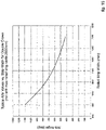
- Fig. 16 shows how the amplitude of the angle ⁇ can vary as a function of the overall width of the rolled strip S, for example for width values comprised between 800 and 2000 mm in the case of a strip S having a double crown.
- multiple crown rolling requires strict control of the cooling efficiency on the width of the work roll, so that it can be selectively varied from the center to the periphery.
- a cooling system 30 comprising one or more ramps 33 for delivering a cooling fluid with respective main feed pipes 31 and delivery nozzles 32 distributed over the entire width of the work rolls 24a, 24b.
- the delivery nozzles 32 are disposed adjacent to each other with a determinate pitch in a double or triple row and are connected, in groups, to the pipes 31, independent from each other, so as to define independent and differentiated cooling zones on the width of the rolls.
- the ramp is divided into eleven independent cooling zones.
- Each feed pipe 31 is equipped with its own proportional valve that regulates the flow rate to the respective group of nozzles 32.
- each delivery ramp 33 can be divided into a plurality of independent zones, for example between 7 and 17. It is therefore possible to define suitable variations of cooling efficiency, along the axis of the work roll 24a, 24b, in particular in order to separately control the cooling on the two halves of the strip, or on the three, four or more portions into which the strip S will be subsequently divided.
- the thermal crown can be controlled so that it follows the trend of the mechanical crown.
- the width of each zone can vary from about 130 mm to about 220 mm.
- the cooling system 30 can comprise four cooling ramps 33 for each of the multiple crown finishing stands 16a-16e, disposed in pairs at entry and at exit to the upper 24a and lower 24b work rolls.
- the cooling ramps 33 can advantageously be provided with drive devices 34 configured to move them toward/away from the respective work roll 24a, 24b, or rotate them with respect thereto, in order to modify the angle of incidence of the cooling liquid on the work roll 24a, 24b.
- the strip S can be cut longitudinally in the processes downstream of the rolling mill 12, and then be entirely wound into coils with multiple crown profile.
- the strip S is wound for an initial head segment with a multiple crown profile, and subsequently a cutting disk located upstream of the reel 21 is driven in order to longitudinally divide the strip S while the winding continues.
- the longitudinal cutting can be interrupted before the final tail end, which therefore remains whole as the head, with a multiple crown profile.
Landscapes
- Engineering & Computer Science (AREA)
- Mechanical Engineering (AREA)
- Physics & Mathematics (AREA)
- Geometry (AREA)
- Metal Rolling (AREA)
- Control Of Metal Rolling (AREA)
- Reduction Rolling/Reduction Stand/Operation Of Reduction Machine (AREA)
- Laminated Bodies (AREA)
Applications Claiming Priority (1)
| Application Number | Priority Date | Filing Date | Title |
|---|---|---|---|
| IT102021000005663A IT202100005663A1 (it) | 2021-03-10 | 2021-03-10 | Procedimento ed impianto per la produzione di prodotti laminati piani |
Publications (3)
| Publication Number | Publication Date |
|---|---|
| EP4056293A1 true EP4056293A1 (de) | 2022-09-14 |
| EP4056293C0 EP4056293C0 (de) | 2025-01-29 |
| EP4056293B1 EP4056293B1 (de) | 2025-01-29 |
Family
ID=75870377
Family Applications (1)
| Application Number | Title | Priority Date | Filing Date |
|---|---|---|---|
| EP21172611.2A Active EP4056293B1 (de) | 2021-03-10 | 2021-05-06 | Verfahren und anlage zur herstellung von flachwalzprodukten |
Country Status (10)
| Country | Link |
|---|---|
| US (2) | US20220288659A1 (de) |
| EP (1) | EP4056293B1 (de) |
| JP (1) | JP7698054B2 (de) |
| KR (1) | KR20230156743A (de) |
| CN (1) | CN115069774B (de) |
| BR (1) | BR112023017924A2 (de) |
| CA (1) | CA3209564A1 (de) |
| IT (1) | IT202100005663A1 (de) |
| MX (1) | MX2023010608A (de) |
| WO (1) | WO2022190149A1 (de) |
Citations (5)
| Publication number | Priority date | Publication date | Assignee | Title |
|---|---|---|---|---|
| JPS5194453A (en) * | 1975-02-18 | 1976-08-19 | Reienyobozaino seizohoho | |
| JPS57175003A (en) | 1981-04-21 | 1982-10-27 | Sumitomo Metal Ind Ltd | Rolling method for double width slab |
| GB2114034A (en) * | 1982-02-03 | 1983-08-17 | Bwg Bergwerk Walzwerk | Process and pickling line for production of metal strip from hot-rolled strip, more particularly wide hot-rolled strip |
| JPH0550122A (ja) * | 1991-08-21 | 1993-03-02 | Ishikawajima Harima Heavy Ind Co Ltd | 圧延ロールの熱クラウン制御装置 |
| WO2014046211A1 (ja) * | 2012-09-20 | 2014-03-27 | 株式会社Ihi | 連続圧延設備 |
Family Cites Families (10)
| Publication number | Priority date | Publication date | Assignee | Title |
|---|---|---|---|---|
| JPS5853302A (ja) * | 1981-09-24 | 1983-03-29 | Mitsubishi Heavy Ind Ltd | 多段クラスタ圧延機の圧延方法 |
| JPS58218306A (ja) * | 1982-06-11 | 1983-12-19 | Hitachi Ltd | 倍尺圧延設備 |
| JPS62214803A (ja) * | 1986-03-15 | 1987-09-21 | Nippon Steel Corp | 異形断面鋼板の安定圧延方法 |
| JP3826974B2 (ja) * | 1997-05-29 | 2006-09-27 | 石川島播磨重工業株式会社 | 熱間タンデム圧延機 |
| JP3495909B2 (ja) * | 1998-03-30 | 2004-02-09 | 株式会社東芝 | 圧延ロールのプロフィール制御装置 |
| DE10043281B4 (de) * | 2000-04-08 | 2004-04-15 | ACHENBACH BUSCHHüTTEN GMBH | Walzenkühl- und/oder Schmiervorrichtung für Kaltbandwalzwerke, insbesondere Feinband- und Folienwalzwerke |
| PL2026916T3 (pl) | 2006-06-14 | 2012-12-31 | Primetals Technologies Austria GmbH | Klatka walcownicza do wytwarzania taśmy walcowanej lub blachy |
| DE102006051728B4 (de) * | 2006-10-30 | 2013-11-21 | Outokumpu Nirosta Gmbh | Verfahren zum Walzen von Metallbändern, inbesondere von Stahlbändern |
| CN101559437B (zh) * | 2009-05-20 | 2012-01-04 | 燕山大学 | 四辊冷连轧机以复合浪防治为目标的辊型曲线设计方法 |
| CN108941204B (zh) * | 2018-06-04 | 2019-11-12 | 北京科技大学 | 一种双锥度工作辊及其辊形设计方法 |
-
2021
- 2021-03-10 IT IT102021000005663A patent/IT202100005663A1/it unknown
- 2021-05-06 US US17/313,825 patent/US20220288659A1/en not_active Abandoned
- 2021-05-06 EP EP21172611.2A patent/EP4056293B1/de active Active
- 2021-05-14 CN CN202110528730.9A patent/CN115069774B/zh active Active
-
2022
- 2022-02-28 BR BR112023017924A patent/BR112023017924A2/pt active Search and Examination
- 2022-02-28 MX MX2023010608A patent/MX2023010608A/es unknown
- 2022-02-28 WO PCT/IT2022/050038 patent/WO2022190149A1/en not_active Ceased
- 2022-02-28 CA CA3209564A patent/CA3209564A1/en active Pending
- 2022-02-28 JP JP2023554923A patent/JP7698054B2/ja active Active
- 2022-02-28 KR KR1020237034505A patent/KR20230156743A/ko active Pending
-
2023
- 2023-07-13 US US18/352,070 patent/US12186789B2/en active Active
Patent Citations (5)
| Publication number | Priority date | Publication date | Assignee | Title |
|---|---|---|---|---|
| JPS5194453A (en) * | 1975-02-18 | 1976-08-19 | Reienyobozaino seizohoho | |
| JPS57175003A (en) | 1981-04-21 | 1982-10-27 | Sumitomo Metal Ind Ltd | Rolling method for double width slab |
| GB2114034A (en) * | 1982-02-03 | 1983-08-17 | Bwg Bergwerk Walzwerk | Process and pickling line for production of metal strip from hot-rolled strip, more particularly wide hot-rolled strip |
| JPH0550122A (ja) * | 1991-08-21 | 1993-03-02 | Ishikawajima Harima Heavy Ind Co Ltd | 圧延ロールの熱クラウン制御装置 |
| WO2014046211A1 (ja) * | 2012-09-20 | 2014-03-27 | 株式会社Ihi | 連続圧延設備 |
Non-Patent Citations (1)
| Title |
|---|
| PIGANI ALESSANDRO ET AL: "Danieli Universal Endless (DUE)", BHM. BERG UND HUETTENMAENNISCHE MONATSHEFTE, SPRINGER, VIENNA, AU, vol. 161, no. 9, 9 September 2016 (2016-09-09), pages 429 - 439, XP036059536, ISSN: 0005-8912, [retrieved on 20160909], DOI: 10.1007/S00501-016-0521-3 * |
Also Published As
| Publication number | Publication date |
|---|---|
| US20220288659A1 (en) | 2022-09-15 |
| MX2023010608A (es) | 2023-10-03 |
| JP2024514753A (ja) | 2024-04-03 |
| CA3209564A1 (en) | 2022-09-15 |
| IT202100005663A1 (it) | 2022-09-10 |
| JP7698054B2 (ja) | 2025-06-24 |
| US12186789B2 (en) | 2025-01-07 |
| WO2022190149A1 (en) | 2022-09-15 |
| BR112023017924A2 (pt) | 2023-10-31 |
| CN115069774A (zh) | 2022-09-20 |
| US20240058853A1 (en) | 2024-02-22 |
| KR20230156743A (ko) | 2023-11-14 |
| CN115069774B (zh) | 2025-09-26 |
| EP4056293C0 (de) | 2025-01-29 |
| EP4056293B1 (de) | 2025-01-29 |
Similar Documents
| Publication | Publication Date | Title |
|---|---|---|
| EP0510147B1 (de) | System und verfahren zum formen dünner flacher warmgewalzter metallbänder | |
| JP7404545B2 (ja) | 板状の金属製品を製造するための方法および装置 | |
| CN87107665A (zh) | 扁坯铸造机的后置多机架连续轧机 | |
| US4106318A (en) | Method and apparatus for rolling metallic material | |
| EP4056293B1 (de) | Verfahren und anlage zur herstellung von flachwalzprodukten | |
| EP4373623B1 (de) | Sexto-walzanlagengerüst, fertigwalzstrasse zum warmwalzen eines mittleren bandes in ein dünnes band und verfahren zu herstellung eines dünnen bandes | |
| US6463777B1 (en) | Method for the continuous production of a metal strip | |
| RU2783290C2 (ru) | Способ и установка для изготовления плоских прокатных изделий | |
| JPH08117829A (ja) | 薄鋼板の冷間圧延方法 | |
| CN110369515B (zh) | 一种铝热连轧机组薄板带的变规格穿带控制方法 | |
| RU2735643C1 (ru) | Способ и устройство для изготовления продуктов плоского металлопроката | |
| JP2761796B2 (ja) | 冷間圧延におけるクラウン制御方法 | |
| CN119076612B (zh) | 一种改善高牌号无取向硅钢毛边卷冷轧边部质量的方法 | |
| RU2375129C1 (ru) | Способ и устройство для изготовления металлической полосы путем бесслитковой прокатки | |
| JP2004001031A (ja) | 金属板の冷間圧延方法 | |
| US20260048427A1 (en) | Method for producing metal strips by continuous casting and rolling | |
| JP2014180677A (ja) | 板幅方向に板厚差を有する差厚鋼板の製造装置および製造方法 | |
| JPH06218404A (ja) | エッジドロップの小さい冷延鋼板の製造方法 | |
| JPS63171255A (ja) | 未凝固圧延方法 | |
| JP6089831B2 (ja) | 板幅方向に左右対称の板厚差を有する差厚鋼板の製造方法 | |
| EP1547700A1 (de) | Einrichtung zum kontinuierlichen warmwalzen | |
| US20050016242A1 (en) | Continous hot-rolling facility | |
| JP2025527472A (ja) | 鋳造ロールによって金属ストリップを製造するための方法 | |
| SU1419765A1 (ru) | Способ гор чей прокатки листов | |
| JP3543234B2 (ja) | 完全連続冷間圧延におけるエッジドロップ制御方法 |
Legal Events
| Date | Code | Title | Description |
|---|---|---|---|
| PUAI | Public reference made under article 153(3) epc to a published international application that has entered the european phase |
Free format text: ORIGINAL CODE: 0009012 |
|
| STAA | Information on the status of an ep patent application or granted ep patent |
Free format text: STATUS: REQUEST FOR EXAMINATION WAS MADE |
|
| 17P | Request for examination filed |
Effective date: 20210506 |
|
| AK | Designated contracting states |
Kind code of ref document: A1 Designated state(s): AL AT BE BG CH CY CZ DE DK EE ES FI FR GB GR HR HU IE IS IT LI LT LU LV MC MK MT NL NO PL PT RO RS SE SI SK SM TR |
|
| P01 | Opt-out of the competence of the unified patent court (upc) registered |
Effective date: 20230517 |
|
| STAA | Information on the status of an ep patent application or granted ep patent |
Free format text: STATUS: EXAMINATION IS IN PROGRESS |
|
| 17Q | First examination report despatched |
Effective date: 20231206 |
|
| GRAP | Despatch of communication of intention to grant a patent |
Free format text: ORIGINAL CODE: EPIDOSNIGR1 |
|
| STAA | Information on the status of an ep patent application or granted ep patent |
Free format text: STATUS: GRANT OF PATENT IS INTENDED |
|
| INTG | Intention to grant announced |
Effective date: 20240906 |
|
| GRAS | Grant fee paid |
Free format text: ORIGINAL CODE: EPIDOSNIGR3 |
|
| GRAA | (expected) grant |
Free format text: ORIGINAL CODE: 0009210 |
|
| STAA | Information on the status of an ep patent application or granted ep patent |
Free format text: STATUS: THE PATENT HAS BEEN GRANTED |
|
| AK | Designated contracting states |
Kind code of ref document: B1 Designated state(s): AL AT BE BG CH CY CZ DE DK EE ES FI FR GB GR HR HU IE IS IT LI LT LU LV MC MK MT NL NO PL PT RO RS SE SI SK SM TR |
|
| REG | Reference to a national code |
Ref country code: GB Ref legal event code: FG4D |
|
| REG | Reference to a national code |
Ref country code: CH Ref legal event code: EP |
|
| REG | Reference to a national code |
Ref country code: DE Ref legal event code: R096 Ref document number: 602021025297 Country of ref document: DE |
|
| REG | Reference to a national code |
Ref country code: IE Ref legal event code: FG4D |
|
| U01 | Request for unitary effect filed |
Effective date: 20250205 |
|
| U07 | Unitary effect registered |
Designated state(s): AT BE BG DE DK EE FI FR IT LT LU LV MT NL PT RO SE SI Effective date: 20250211 |
|
| P04 | Withdrawal of opt-out of the competence of the unified patent court (upc) registered |
Free format text: CASE NUMBER: APP_6418/2025 Effective date: 20250207 |
|
| U20 | Renewal fee for the european patent with unitary effect paid |
Year of fee payment: 5 Effective date: 20250527 |
|
| PG25 | Lapsed in a contracting state [announced via postgrant information from national office to epo] |
Ref country code: RS Free format text: LAPSE BECAUSE OF FAILURE TO SUBMIT A TRANSLATION OF THE DESCRIPTION OR TO PAY THE FEE WITHIN THE PRESCRIBED TIME-LIMIT Effective date: 20250429 |
|
| PG25 | Lapsed in a contracting state [announced via postgrant information from national office to epo] |
Ref country code: PL Free format text: LAPSE BECAUSE OF FAILURE TO SUBMIT A TRANSLATION OF THE DESCRIPTION OR TO PAY THE FEE WITHIN THE PRESCRIBED TIME-LIMIT Effective date: 20250129 |
|
| PG25 | Lapsed in a contracting state [announced via postgrant information from national office to epo] |
Ref country code: ES Free format text: LAPSE BECAUSE OF FAILURE TO SUBMIT A TRANSLATION OF THE DESCRIPTION OR TO PAY THE FEE WITHIN THE PRESCRIBED TIME-LIMIT Effective date: 20250129 |
|
| PG25 | Lapsed in a contracting state [announced via postgrant information from national office to epo] |
Ref country code: NO Free format text: LAPSE BECAUSE OF FAILURE TO SUBMIT A TRANSLATION OF THE DESCRIPTION OR TO PAY THE FEE WITHIN THE PRESCRIBED TIME-LIMIT Effective date: 20250429 Ref country code: IS Free format text: LAPSE BECAUSE OF FAILURE TO SUBMIT A TRANSLATION OF THE DESCRIPTION OR TO PAY THE FEE WITHIN THE PRESCRIBED TIME-LIMIT Effective date: 20250529 |
|
| PG25 | Lapsed in a contracting state [announced via postgrant information from national office to epo] |
Ref country code: HR Free format text: LAPSE BECAUSE OF FAILURE TO SUBMIT A TRANSLATION OF THE DESCRIPTION OR TO PAY THE FEE WITHIN THE PRESCRIBED TIME-LIMIT Effective date: 20250129 |
|
| PG25 | Lapsed in a contracting state [announced via postgrant information from national office to epo] |
Ref country code: GR Free format text: LAPSE BECAUSE OF FAILURE TO SUBMIT A TRANSLATION OF THE DESCRIPTION OR TO PAY THE FEE WITHIN THE PRESCRIBED TIME-LIMIT Effective date: 20250430 |
|
| PG25 | Lapsed in a contracting state [announced via postgrant information from national office to epo] |
Ref country code: SM Free format text: LAPSE BECAUSE OF FAILURE TO SUBMIT A TRANSLATION OF THE DESCRIPTION OR TO PAY THE FEE WITHIN THE PRESCRIBED TIME-LIMIT Effective date: 20250129 |
|
| PG25 | Lapsed in a contracting state [announced via postgrant information from national office to epo] |
Ref country code: CZ Free format text: LAPSE BECAUSE OF FAILURE TO SUBMIT A TRANSLATION OF THE DESCRIPTION OR TO PAY THE FEE WITHIN THE PRESCRIBED TIME-LIMIT Effective date: 20250129 |
|
| PG25 | Lapsed in a contracting state [announced via postgrant information from national office to epo] |
Ref country code: SK Free format text: LAPSE BECAUSE OF FAILURE TO SUBMIT A TRANSLATION OF THE DESCRIPTION OR TO PAY THE FEE WITHIN THE PRESCRIBED TIME-LIMIT Effective date: 20250129 |
|
| PLBE | No opposition filed within time limit |
Free format text: ORIGINAL CODE: 0009261 |
|
| STAA | Information on the status of an ep patent application or granted ep patent |
Free format text: STATUS: NO OPPOSITION FILED WITHIN TIME LIMIT |
|
| REG | Reference to a national code |
Ref country code: CH Ref legal event code: L10 Free format text: ST27 STATUS EVENT CODE: U-0-0-L10-L00 (AS PROVIDED BY THE NATIONAL OFFICE) Effective date: 20251210 |
|
| REG | Reference to a national code |
Ref country code: CH Ref legal event code: H13 Free format text: ST27 STATUS EVENT CODE: U-0-0-H10-H13 (AS PROVIDED BY THE NATIONAL OFFICE) Effective date: 20251223 |
|
| 26N | No opposition filed |
Effective date: 20251030 |
|
| PG25 | Lapsed in a contracting state [announced via postgrant information from national office to epo] |
Ref country code: CH Free format text: LAPSE BECAUSE OF NON-PAYMENT OF DUE FEES Effective date: 20250531 |
|
| GBPC | Gb: european patent ceased through non-payment of renewal fee |
Effective date: 20250506 |
|
| PG25 | Lapsed in a contracting state [announced via postgrant information from national office to epo] |
Ref country code: MC Free format text: LAPSE BECAUSE OF FAILURE TO SUBMIT A TRANSLATION OF THE DESCRIPTION OR TO PAY THE FEE WITHIN THE PRESCRIBED TIME-LIMIT Effective date: 20250129 |