EP4054974B1 - Getränkeausgabesystem - Google Patents
Getränkeausgabesystem Download PDFInfo
- Publication number
- EP4054974B1 EP4054974B1 EP20800659.3A EP20800659A EP4054974B1 EP 4054974 B1 EP4054974 B1 EP 4054974B1 EP 20800659 A EP20800659 A EP 20800659A EP 4054974 B1 EP4054974 B1 EP 4054974B1
- Authority
- EP
- European Patent Office
- Prior art keywords
- beverage
- cabinet
- beverage container
- dispensing system
- cooling
- Prior art date
- Legal status (The legal status is an assumption and is not a legal conclusion. Google has not performed a legal analysis and makes no representation as to the accuracy of the status listed.)
- Active
Links
Images


Classifications
-
- B—PERFORMING OPERATIONS; TRANSPORTING
- B67—OPENING, CLOSING OR CLEANING BOTTLES, JARS OR SIMILAR CONTAINERS; LIQUID HANDLING
- B67D—DISPENSING, DELIVERING OR TRANSFERRING LIQUIDS, NOT OTHERWISE PROVIDED FOR
- B67D1/00—Apparatus or devices for dispensing beverages on draught
- B67D1/08—Details
- B67D1/0857—Cooling arrangements
- B67D1/0858—Cooling arrangements using compression systems
- B67D1/0861—Cooling arrangements using compression systems the evaporator acting through an intermediate heat transfer means
-
- B—PERFORMING OPERATIONS; TRANSPORTING
- B67—OPENING, CLOSING OR CLEANING BOTTLES, JARS OR SIMILAR CONTAINERS; LIQUID HANDLING
- B67D—DISPENSING, DELIVERING OR TRANSFERRING LIQUIDS, NOT OTHERWISE PROVIDED FOR
- B67D1/00—Apparatus or devices for dispensing beverages on draught
- B67D1/06—Mountings or arrangements of dispensing apparatus in or on shop or bar counters
-
- B—PERFORMING OPERATIONS; TRANSPORTING
- B67—OPENING, CLOSING OR CLEANING BOTTLES, JARS OR SIMILAR CONTAINERS; LIQUID HANDLING
- B67D—DISPENSING, DELIVERING OR TRANSFERRING LIQUIDS, NOT OTHERWISE PROVIDED FOR
- B67D2210/00—Indexing scheme relating to aspects and details of apparatus or devices for dispensing beverages on draught or for controlling flow of liquids under gravity from storage containers for dispensing purposes
- B67D2210/00028—Constructional details
- B67D2210/00031—Housing
- B67D2210/00034—Modules
-
- B—PERFORMING OPERATIONS; TRANSPORTING
- B67—OPENING, CLOSING OR CLEANING BOTTLES, JARS OR SIMILAR CONTAINERS; LIQUID HANDLING
- B67D—DISPENSING, DELIVERING OR TRANSFERRING LIQUIDS, NOT OTHERWISE PROVIDED FOR
- B67D2210/00—Indexing scheme relating to aspects and details of apparatus or devices for dispensing beverages on draught or for controlling flow of liquids under gravity from storage containers for dispensing purposes
- B67D2210/00028—Constructional details
- B67D2210/00031—Housing
- B67D2210/00039—Panels
-
- B—PERFORMING OPERATIONS; TRANSPORTING
- B67—OPENING, CLOSING OR CLEANING BOTTLES, JARS OR SIMILAR CONTAINERS; LIQUID HANDLING
- B67D—DISPENSING, DELIVERING OR TRANSFERRING LIQUIDS, NOT OTHERWISE PROVIDED FOR
- B67D2210/00—Indexing scheme relating to aspects and details of apparatus or devices for dispensing beverages on draught or for controlling flow of liquids under gravity from storage containers for dispensing purposes
- B67D2210/00028—Constructional details
- B67D2210/00128—Constructional details relating to outdoor use; movable; portable
- B67D2210/00133—Constructional details relating to outdoor use; movable; portable wheeled
- B67D2210/00139—Trolleys
Definitions
- the present invention relates to a beverage dispensing system for dispensing cooled beverages, such as soft drinks, wine, cider or beer.
- Beverage dispensing systems are known from, for example, EP 3 260 412 and WO 2005/106366 . Over the last decades the dispensing systems have been designed for enhancing the taste experience of the beverage by, for instance, avoiding contamination of dispensing lines and other measures. However, the beverage dispensing systems have become more specialised and thereby as a consequence bulkier.
- the components being connected with each other to form a single unit, which will facilitate attaching and detaching the cooling module in or from the inside of the cabinet.
- the cabinet may have wheels arranged below the bottom face.
- the top face may have an opening, the tapping head is arranged opposite the opening.
- tapping head is detachable connected with the cabinet, so that it may be dismounted in periods where the beverage dispensing system is not in use.
- the tapping head comprises a tower having an interior channel wherein the dispensing line can be guided from the beverage container to the tapping head.
- the interior channel may have a size enabling the dispensing line to be guided through the interior channel, either from the tapping head or from the cabinet. This is especially advantageous in circumstances where the dispensing line is a one-way dispensing line which shall be replaced each time the beverage container is replaced.
- the beverage dispensing concept sold under the tradename FlexiDraft TM may be used together with the present invention.
- the tapping head may be connected with a plate, which plate may be arranged on the top face of the cabinet. This may also enhance the flexibility of the beverage dispensing system, while providing a support face and thereby stability to the tapping head.
- a further advantage is that the top face of the cabinet not necessarily needs to be reinforced.
- the plate may also have recesses to for instance a drip tray. Also, the plate may have substantially the same width as the cabinet.
- the base plate may comprise one or more gaskets arranged around the edges of the base plate for increasing overall cabinet tightness.
- a plurality of fastening means may be arranged at the top face, the fastening means are configured to maintain the plate in position on the top face.
- the cabinet has internal walls, at least two opposite internal walls have a plurality of brackets arranged with a mutual distance from the bottom face to the top face.
- the plate and the tapping head may be arranged inside the cabinet when not in use, wherein the plate is resting on two opposite brackets.
- the plate and tapping head may be inverted before being arranged inside the cabinet.
- the beverage dispensing system may be stored away when not in use in an easy manner, and at the same time ensuring that all the different components are protected inside the cabinet.
- the beverage container may be made of metal or a polymeric material.
- the cooling jacket may cover more than 60% of the outer face of the beverage container, preferably more than 70% of the outer face.
- the cooling capabilities of the cooling module is enhanced.
- the cooling jacket may have a form as a U or ⁇ when seen from a top view.
- tensioning means may be arranged in connection with the cooling jacket, the tensioning means is/are configured to tightening the cooling jacket around the beverage container so that it is ensured that the cooling jacket is in good contact with the outer face of the beverage container so that the intended cooling of the beverage is obtained. Additionally, by using the tensioning means the beverage container is secured properly inside the cabinet.
- the gas cylinder may be arranged in connection with the door.
- a gas regulator may be connected with the gas cylinder.
- the cooling jacket may have a cooling face facing the outer face of the beverage container, a plurality of blocks is arranged on the cooling face so that thermal contact resistance between the beverage container and the cooling jacket of the evaporator is low. In addition, a gap between the cooling jacket of the evaporator and the beverage container are reduced.
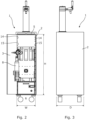
- the beverage dispensing system also comprises a beverage container (not shown) having a cylindric form and an outer face, the beverage container containing a beverage to be dispensed. Furthermore, a dispense head (not shown) may be coupled to the beverage container, and a dispensing line (not shown) extending from the dispense head to a tapping head 7. The dispensing line is configured to lead the beverage from the beverage container to the tapping head for dispensing, the tapping head 7 is arranged on the top face 5 of the cabinet 2.
- the top face 5 may have an opening (not shown), the tapping head 7 is arranged opposite the opening.
- the dispensing line may extend from the interior of the cabinet up in the tapping head 7.
- the interior channel may have a size enabling the dispensing line to be guided through the interior channel, either from the tapping head or from the cabinet. This is especially advantageous in circumstances where the dispensing line is a one-way dispensing line which shall be replaced each time the beverage container is replaced.
- the beverage dispensing concept sold under the tradename FlexiDraft TM may be used together with the present invention.
- WO 2013/000932 is incorporated by reference.
- the base plate 19 may be arranged with a small inclination, preferably below 3 degrees so that if any liquid is ending up on the base plate it may be directed in a condense tray 39 located inside the condensing unit.
- the condense tray 39 is shown in Fig. 8
- the base plate has an edge around the perimeter of the base plate.
- One or more gaskets may be arranged at the edge for increasing cabinet tightness by avoiding fluid communication between an evaporator space and a condensing unit space.
- the cooling jacket 18 may cover more than 60% of the outer face of the beverage container, preferably more than 70% of the outer face.
- the cooling capabilities of the cooling module 9 is enhanced.
- cooling jacket 18 may have a form as a U or ⁇ when seen from a top view as shown in Fig. 6 .
- the cooling jacket 18 may have a cooling face 27 facing the outer face of the beverage container, a plurality of blocks 28 is arranged on the cooling face 27 so that thermal contact resistance between the beverage container and the cooling jacket 18 of the evaporator 17 is low. In addition, a gap between the cooling jacket 18 of the evaporator 17 and the beverage container is reduced.
- the blocks 28 may be made of metal, preferably aluminium.
- the blocks 28 may be distributed so as to cover a major part of the cooling face 27.
- a fan may be arranged inside the cabinet for providing airflow inside the cabinet.
- a gasket strip may be arranged in connection with a door frame of the cabinet to increase cabinet tightness. Due to relatively high cabinet temperature, condensation on the door and the walls of the cabinet is avoided.
- the base plate 19 may substantially divide the cooling module 9 with an insulated frame to avoid air circulation below the base plate 9.
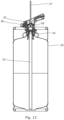
- a beverage container 29 is arranged inside the cabinet 2 of the beverage dispensing system 1.
- the beverage container 29 is placed on the base plate 19 and is encircled by the evaporator.
- tensioning means 30 is/are arranged in connection with the cooling jacket, the tensioning means 30 is/are configured to tightening the cooling jacket around the beverage container 29 as seen in Fig. 9 so that it is ensured that the cooling jacket is in good contact with the outer face 31 of the beverage container 29 so that the intended cooling of the beverage is obtained. Additionally, by using the tensioning means 30 the beverage container is secured properly inside the cabinet.
- the tensioning means 30 are in the present embodiment a strap in each end being connected with the cooling jacket.
- the beverage container 29 may be made of metal or a polymeric material.
- Fig. 10 the beverage container system 1 is shown with the door 3 closed.
- the plate 12 is arranged on the top face of the cabinet 2.
- a plurality of fastening means 32 is arranged at the top face, the fastening means 32 are configured to maintain the plate 12 in position on the top face.
- a simple and flexible way to secure the plate 12 is obtained and thereby the tapping head 7 to the top face of the cabinet.
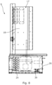
- Figs. 11 and 12 the cabinet 2 is shown in a storage position meaning the tapping head has been demounted from the cabinet 2.
- the door 3 is closed so that the interior of the cabinet 2 is closed too.
- Fig. 12 the door 3 is open whereby it is possible to see the plate 12 and the tapping head 7 arranged inside the cabinet 2 when not in use.
- the plate 12 is resting on two opposite brackets 15.
- the plate 12 and tapping head 7 have been inverted before being arranged inside the cabinet 2.
- the beverage dispensing system 1 may be stored away when not in use in an easy manner and at the same time ensuring that all the different components are protected inside the cabinet.
- the tapping head and plate are fitted inside the cabinet.
- the advantage is that the cabinet in the design as an aircraft cabin service trolley appears to be only a trolley and not a beverage dispensing system.
- Fig. 13 shows a cross-sectional view of a beverage container 29 having an extractor tube 33 or spear arranged in a collar 33 of the beverage container 29 and a dispense head 35 coupled to the extractor tube 33.
- the extractor tubes and dispense heads are well known as well as their function, hence it will not be described in detail here.
- the dispense head 35 has a gas inlet 36 which is fluidly connected with the gas cylinder (not shown).
- the dispensing line 37 is fluidly connected with the dispense head 37.
- the dispensing line 37 comprises a probe 38 which may be inserted into a bore in the dispense head 35.
- the probe is used to activate a double valve of the extractor tube.
- the probe and the dispensing line are in the present embodiment configured to be replaced each time the beverage container is replaced. Hence both the probe and the dispensing line may be made of polymeric materials and may be disposed after use.
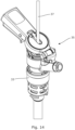
- Fig. 14 shows an embodiment of a dispense head 35 coupled to an extractor tube 33, the dispensing line 37 is connected with the dispense head 35 as mentioned above. Since many different systems of beverage containers, extractor tubes/spears, and thereby also dispense heads to be coupled to the extractor tubes exist, the present invention may be used with any of the known systems, and they will consequently not be described any further here. The embodiment shown in Fig. 14 is only one example of the dispense head which may be used in connection with the present invention.
- the dispensing line 37 is configured to lead the beverage from the beverage container 29 to the tapping head 7 for dispensing, the tapping head 7 is arranged on the top face of the cabinet 2.
- the tapping head 7 comprises a tapping handle 41 for opening and closing the dispensing of beverage of the spout 42.
Landscapes
- Physics & Mathematics (AREA)
- Thermal Sciences (AREA)
- Devices For Dispensing Beverages (AREA)
Claims (13)
- Getränkeausgabesystem (1), umfassendein im Wesentlichen geschlossenes Gehäuse (2), das eine Höhe H, eine Breite W und eine Tiefe D und eine Tür (3) zum Bereitstellen von Zugang zu einem Inneren (4) des Gehäuses (2) aufweist, wobei das Gehäuse eine obere Fläche (5) und eine Bodenfläche (6) aufweist,einen Getränkebehälter (29), der eine Zylinderform und eine Außenfläche (31) aufweist, wobei der Getränkebehälter ein Getränk beinhaltet, das auszugeben ist,einen Ausgabekopf (35), der mit dem Getränkebehälter zu koppeln ist, und eine Ausgabeleitung (37), die sich von dem Ausgabekopf zu einem Zapfkopf (7) erstreckt, wobei die Ausgabeleitung dazu konfiguriert ist, das Getränk von dem Getränkebehälter zu dem Zapfkopf zum Ausgeben zu führen, wobei der Zapfkopf an der oberen Fläche (5) des Gehäuses angeordnet ist,eine Gasflasche (8), die ein Gas aufweist und mit dem Ausgabekopf zum Befördern des Getränks aus dem Getränkebehälter fluidverbunden ist, wenn der Zapfkopf zum Ausgeben geöffnet wird,wobei ein Kühlmodul (9) abnehmbar innerhalb des Gehäuses (2) angeordnet ist, wobei das Kühlmodul (9) dazu konfiguriert ist, das Getränk zu kühlen, das in dem Getränkebehälter beinhaltet ist, wobei das Kühlmodul die folgenden Komponenten umfasst:- einen Verdampfer (17), der als ein Kühlmantel (18) gebildet ist, wobei der Kühlmantel dazu konfiguriert ist, den Getränkebehälter teilweise zu umgeben und in Kontakt mit der Außenfläche (31) des Getränkebehälters zum Kühlen des Getränks zu stehen,- eine Basisplatte (19), auf welcher der Getränkebehälter anzuordnen ist,- einen Temperatursensor (20), der dazu angeordnet ist, in Kontakt mit der Außenfläche des Getränkebehälters zu stehen, wobei der Temperatursensor mit einer Steuervorrichtung (21) wirkverbunden ist, und- eine Kondensationseinheit (22), umfassend einen Kompressor (23), einen Kondensator (24) und eine Expansionsvorrichtung, wobei die Kondensationseinheit (22) dazu konfiguriert ist, eine Temperatur eines Kühlmittels zu verringern und das Kühlmittel zum Kühlen des Kühlmantels (18) umzuwälzen, wobei die Kondensationseinheit (22) und die Steuervorrichtung (21) unterhalb der Basisplatte (19) angeordnet ist,wobei der Zapfkopf (7) abnehmbar mit dem Gehäuse (2) verbunden ist und einen Turm (11) umfasst, der einen Innenkanal aufweist, in welchem die Ausgabeleitung von dem Getränkebehälter zu dem Zapfkopf geleitet werden kann.
- Getränkeausgabesystem (1) nach Anspruch 1, wobei es sich bei dem Verdampfer (17) um einen Roll-Bond-Verdampfer handelt, der einen Kühlmittelkanal aufweist, der entlang der Erstreckung des Verdampfers verteilt ist.
- Getränkeausgabesystem (1) nach einem der vorstehenden Ansprüche, wobei der Verdampfer (17) eine Abdeckung aufweist, die aus polymerem Material hergestellt ist.
- Getränkeausgabesystem (1) nach einem der vorstehenden Ansprüche, wobei die Komponenten, die miteinander verbunden sind, eine einzige Einheit bilden.
- Getränkeausgabesystem (1) nach einem der vorstehenden Ansprüche, wobei es sich bei dem Gehäuse (2) um einen Luftfahrzeugkabinenservierwagen handelt.
- Getränkeausgabesystem (1) nach einem der vorstehenden Ansprüche, wobei der Zapfkopf (7) mit einer Platte (12) verbunden ist, wobei die Platte an der oberen Fläche (5) des Gehäuses angeordnet sein kann.
- Getränkeausgabesystem (1) nach einem der vorstehenden Ansprüche, wobei das Gehäuse (2) Innenwände (14) aufweist, wobei mindestens zwei gegenüberliegende Innenwände (14) eine Vielzahl von Halterungen (15) aufweisen, die mit einem gegenseitigen Abstand von der Bodenfläche zu der oberen Fläche angeordnet ist.
- Getränkeausgabesystem (1) nach Anspruch 7, wobei die Platte (12) und der Zapfkopf (7) bei Nichtgebrauch innerhalb des Gehäuses (2) angeordnet werden können, wobei die Platte (12) auf zwei gegenüberliegenden Halterungen (15) ruht.
- Getränkeausgabesystem (1) nach einem der vorstehenden Ansprüche, wobei der Kühlmantel (18) mehr als 60 % der Außenfläche des Getränkebehälters, vorzugsweise mehr als 70 % der Außenfläche, bedeckt.
- Getränkeausgabesystem (1) nach einem der vorstehenden Ansprüche, wobei ein oder mehrere Spannmittel (30) in Verbindung mit dem Kühlmantel (18) angeordnet ist/sind, wobei das/die Spannmittel dazu konfiguriert ist/sind, den Kühlmantel um den Getränkebehälter herum festzuziehen, so dass sichergestellt wird, dass der Kühlmantel in Kontakt mit der Außenfläche des Getränkebehälters steht.
- Getränkeausgabesystem (1) nach einem der vorstehenden Ansprüche, wobei die Höhe H des Gehäuses (2) mindestens im Wesentlichen doppelt so groß wie die Breite W des Gehäuses (2) ist.
- Getränkeausgabesystem (1) nach einem der vorstehenden Ansprüche, wobei die Gasflasche (8) in Verbindung mit der Tür (3) angeordnet ist.
- Getränkeausgabesystem (1) nach einem der vorstehenden Ansprüche, wobei der Kühlmantel (18) eine Kühlfläche (27) aufweist, die der Außenfläche (31) des Getränkebehälters zugewandt ist, wobei eine Vielzahl von Blöcken (28) auf der Kühlfläche angeordnet ist, so dass der thermische Kontaktwiderstand zwischen dem Getränkebehälter (29) und dem Kühlmantel (18) des Verdampfers (17) gering ist.
Applications Claiming Priority (3)
| Application Number | Priority Date | Filing Date | Title |
|---|---|---|---|
| EP19207970 | 2019-11-08 | ||
| EP19208305.3A EP3819258A1 (de) | 2019-11-11 | 2019-11-11 | Getränkeausgabesystem |
| PCT/EP2020/081235 WO2021089755A1 (en) | 2019-11-08 | 2020-11-06 | A beverage dispensing system |
Publications (3)
| Publication Number | Publication Date |
|---|---|
| EP4054974A1 EP4054974A1 (de) | 2022-09-14 |
| EP4054974C0 EP4054974C0 (de) | 2025-06-11 |
| EP4054974B1 true EP4054974B1 (de) | 2025-06-11 |
Family
ID=73043285
Family Applications (1)
| Application Number | Title | Priority Date | Filing Date |
|---|---|---|---|
| EP20800659.3A Active EP4054974B1 (de) | 2019-11-08 | 2020-11-06 | Getränkeausgabesystem |
Country Status (3)
| Country | Link |
|---|---|
| EP (1) | EP4054974B1 (de) |
| CN (1) | CN114929616B (de) |
| WO (1) | WO2021089755A1 (de) |
Family Cites Families (9)
| Publication number | Priority date | Publication date | Assignee | Title |
|---|---|---|---|---|
| US2199718A (en) * | 1939-05-15 | 1940-05-07 | Ray C Ayers | Beer cooler |
| US7267247B1 (en) * | 2003-09-25 | 2007-09-11 | Crunkleton Iii James T | Portable beverage dispensing system |
| GB0409900D0 (en) * | 2004-05-04 | 2004-06-09 | Imi Cornelius Uk Ltd | Beverage dispense system |
| US7140196B2 (en) * | 2004-11-30 | 2006-11-28 | Grindmaster Corporation | Chilled beverage dispenser with cradle evaporator |
| MY163766A (en) * | 2005-08-12 | 2017-10-31 | Carlsberg Breweries As | An assembly for dispensing beverage |
| JP5637744B2 (ja) * | 2010-06-15 | 2014-12-10 | ホシザキ電機株式会社 | 飲料ディスペンサ |
| EA028563B1 (ru) | 2011-06-28 | 2017-12-29 | Микро Матик А/С | Система выдачи напитка |
| US10053355B2 (en) * | 2016-06-20 | 2018-08-21 | The Boeing Company | Adaptable insulated galley cart carbonated beverage delivery system |
| CN106322916B (zh) * | 2016-10-11 | 2022-07-29 | 塔罗斯科技股份有限公司 | 一种双冷式扎啤机 |
-
2020
- 2020-11-06 CN CN202080091922.1A patent/CN114929616B/zh active Active
- 2020-11-06 WO PCT/EP2020/081235 patent/WO2021089755A1/en not_active Ceased
- 2020-11-06 EP EP20800659.3A patent/EP4054974B1/de active Active
Also Published As
| Publication number | Publication date |
|---|---|
| CN114929616B (zh) | 2025-12-09 |
| EP4054974C0 (de) | 2025-06-11 |
| WO2021089755A1 (en) | 2021-05-14 |
| CN114929616A (zh) | 2022-08-19 |
| EP4054974A1 (de) | 2022-09-14 |
Similar Documents
| Publication | Publication Date | Title |
|---|---|---|
| US7861892B1 (en) | Portable draft bar | |
| US5339986A (en) | Method of dispensing beverage | |
| US6434961B2 (en) | Food preserving systems | |
| US20110108240A1 (en) | Tapping apparatus and cooling apparatus with two heat exchangers and method for the formation of a tapping or cooling apparatus | |
| US8596496B2 (en) | Wine storage and dispensing apparatus | |
| US20110100049A1 (en) | Countermount, tapping apparatus and method for regulating the temperature of beverage | |
| US20030062386A1 (en) | Airflow method and system for controlling temperature of a liquid dispenser | |
| US20190204004A1 (en) | Aircraft galley | |
| KR20190109103A (ko) | 음료 냉각 장치 | |
| US10222112B2 (en) | Refrigeration device having an ice maker | |
| EP2543947A1 (de) | Kryogenwärmerohrwärmetauscher | |
| EP4054974B1 (de) | Getränkeausgabesystem | |
| EP3981735A1 (de) | Getränkeabgabeanordnung und ventilbetätigungsvorrichtung dafür | |
| EP3819258A1 (de) | Getränkeausgabesystem | |
| HK40072939A (en) | A beverage dispensing system | |
| WO1997000411A1 (en) | Apparatus and method for cooling of liquids | |
| US11566837B2 (en) | Home appliance device and method for assembling the home appliance device | |
| EP1756495A1 (de) | Getränkeabgabesystem | |
| GB2223000A (en) | Cabinet with dispensing means | |
| KR101346963B1 (ko) | 와인 냉각장치 | |
| CN103518112A (zh) | 家用制冷器具 | |
| KR101576440B1 (ko) | 빙결관을 이용한 멀티형 음료 냉각 인출 장치 | |
| WO2010134801A1 (en) | Tapping apparatus and cooling circuit for a tapping apparatus | |
| US20250243047A1 (en) | Carbonator and cold-plate system | |
| US11493264B2 (en) | Home appliance device and method of manufacturing the home appliance device |
Legal Events
| Date | Code | Title | Description |
|---|---|---|---|
| STAA | Information on the status of an ep patent application or granted ep patent |
Free format text: STATUS: UNKNOWN |
|
| STAA | Information on the status of an ep patent application or granted ep patent |
Free format text: STATUS: THE INTERNATIONAL PUBLICATION HAS BEEN MADE |
|
| PUAI | Public reference made under article 153(3) epc to a published international application that has entered the european phase |
Free format text: ORIGINAL CODE: 0009012 |
|
| STAA | Information on the status of an ep patent application or granted ep patent |
Free format text: STATUS: REQUEST FOR EXAMINATION WAS MADE |
|
| 17P | Request for examination filed |
Effective date: 20220524 |
|
| AK | Designated contracting states |
Kind code of ref document: A1 Designated state(s): AL AT BE BG CH CY CZ DE DK EE ES FI FR GB GR HR HU IE IS IT LI LT LU LV MC MK MT NL NO PL PT RO RS SE SI SK SM TR |
|
| DAV | Request for validation of the european patent (deleted) | ||
| DAX | Request for extension of the european patent (deleted) | ||
| GRAP | Despatch of communication of intention to grant a patent |
Free format text: ORIGINAL CODE: EPIDOSNIGR1 |
|
| STAA | Information on the status of an ep patent application or granted ep patent |
Free format text: STATUS: GRANT OF PATENT IS INTENDED |
|
| INTG | Intention to grant announced |
Effective date: 20250227 |
|
| GRAS | Grant fee paid |
Free format text: ORIGINAL CODE: EPIDOSNIGR3 |
|
| GRAA | (expected) grant |
Free format text: ORIGINAL CODE: 0009210 |
|
| STAA | Information on the status of an ep patent application or granted ep patent |
Free format text: STATUS: THE PATENT HAS BEEN GRANTED |
|
| AK | Designated contracting states |
Kind code of ref document: B1 Designated state(s): AL AT BE BG CH CY CZ DE DK EE ES FI FR GB GR HR HU IE IS IT LI LT LU LV MC MK MT NL NO PL PT RO RS SE SI SK SM TR |
|
| REG | Reference to a national code |
Ref country code: GB Ref legal event code: FG4D |
|
| REG | Reference to a national code |
Ref country code: CH Ref legal event code: EP |
|
| REG | Reference to a national code |
Ref country code: IE Ref legal event code: FG4D |
|
| REG | Reference to a national code |
Ref country code: DE Ref legal event code: R096 Ref document number: 602020052684 Country of ref document: DE |
|
| U01 | Request for unitary effect filed |
Effective date: 20250704 |
|
| U07 | Unitary effect registered |
Designated state(s): AT BE BG DE DK EE FI FR IT LT LU LV MT NL PT RO SE SI Effective date: 20250711 |
|
| PG25 | Lapsed in a contracting state [announced via postgrant information from national office to epo] |
Ref country code: ES Free format text: LAPSE BECAUSE OF FAILURE TO SUBMIT A TRANSLATION OF THE DESCRIPTION OR TO PAY THE FEE WITHIN THE PRESCRIBED TIME-LIMIT Effective date: 20250611 |
|
| PG25 | Lapsed in a contracting state [announced via postgrant information from national office to epo] |
Ref country code: NO Free format text: LAPSE BECAUSE OF FAILURE TO SUBMIT A TRANSLATION OF THE DESCRIPTION OR TO PAY THE FEE WITHIN THE PRESCRIBED TIME-LIMIT Effective date: 20250911 Ref country code: GR Free format text: LAPSE BECAUSE OF FAILURE TO SUBMIT A TRANSLATION OF THE DESCRIPTION OR TO PAY THE FEE WITHIN THE PRESCRIBED TIME-LIMIT Effective date: 20250912 |
|
| PGFP | Annual fee paid to national office [announced via postgrant information from national office to epo] |
Ref country code: GB Payment date: 20250918 Year of fee payment: 6 |
|
| PG25 | Lapsed in a contracting state [announced via postgrant information from national office to epo] |
Ref country code: HR Free format text: LAPSE BECAUSE OF FAILURE TO SUBMIT A TRANSLATION OF THE DESCRIPTION OR TO PAY THE FEE WITHIN THE PRESCRIBED TIME-LIMIT Effective date: 20250611 |
|
| PG25 | Lapsed in a contracting state [announced via postgrant information from national office to epo] |
Ref country code: RS Free format text: LAPSE BECAUSE OF FAILURE TO SUBMIT A TRANSLATION OF THE DESCRIPTION OR TO PAY THE FEE WITHIN THE PRESCRIBED TIME-LIMIT Effective date: 20250911 |
|
| U20 | Renewal fee for the european patent with unitary effect paid |
Year of fee payment: 6 Effective date: 20250923 |
|
| PG25 | Lapsed in a contracting state [announced via postgrant information from national office to epo] |
Ref country code: IS Free format text: LAPSE BECAUSE OF FAILURE TO SUBMIT A TRANSLATION OF THE DESCRIPTION OR TO PAY THE FEE WITHIN THE PRESCRIBED TIME-LIMIT Effective date: 20251011 |
|
| PG25 | Lapsed in a contracting state [announced via postgrant information from national office to epo] |
Ref country code: SM Free format text: LAPSE BECAUSE OF FAILURE TO SUBMIT A TRANSLATION OF THE DESCRIPTION OR TO PAY THE FEE WITHIN THE PRESCRIBED TIME-LIMIT Effective date: 20250611 |
|
| PG25 | Lapsed in a contracting state [announced via postgrant information from national office to epo] |
Ref country code: CZ Free format text: LAPSE BECAUSE OF FAILURE TO SUBMIT A TRANSLATION OF THE DESCRIPTION OR TO PAY THE FEE WITHIN THE PRESCRIBED TIME-LIMIT Effective date: 20250611 |
|
| PG25 | Lapsed in a contracting state [announced via postgrant information from national office to epo] |
Ref country code: PL Free format text: LAPSE BECAUSE OF FAILURE TO SUBMIT A TRANSLATION OF THE DESCRIPTION OR TO PAY THE FEE WITHIN THE PRESCRIBED TIME-LIMIT Effective date: 20250611 |
|
| PG25 | Lapsed in a contracting state [announced via postgrant information from national office to epo] |
Ref country code: SK Free format text: LAPSE BECAUSE OF FAILURE TO SUBMIT A TRANSLATION OF THE DESCRIPTION OR TO PAY THE FEE WITHIN THE PRESCRIBED TIME-LIMIT Effective date: 20250611 |
|
| PLBE | No opposition filed within time limit |
Free format text: ORIGINAL CODE: 0009261 |
|
| STAA | Information on the status of an ep patent application or granted ep patent |
Free format text: STATUS: NO OPPOSITION FILED WITHIN TIME LIMIT |
|
| REG | Reference to a national code |
Ref country code: CH Ref legal event code: L10 Free format text: ST27 STATUS EVENT CODE: U-0-0-L10-L00 (AS PROVIDED BY THE NATIONAL OFFICE) Effective date: 20260423 |