EP4054024B1 - Passive detektion von überhitzung in einem leistungsverbinder - Google Patents
Passive detektion von überhitzung in einem leistungsverbinder Download PDFInfo
- Publication number
- EP4054024B1 EP4054024B1 EP22159791.7A EP22159791A EP4054024B1 EP 4054024 B1 EP4054024 B1 EP 4054024B1 EP 22159791 A EP22159791 A EP 22159791A EP 4054024 B1 EP4054024 B1 EP 4054024B1
- Authority
- EP
- European Patent Office
- Prior art keywords
- connector
- conductive component
- low
- insulating element
- electrically insulating
- Prior art date
- Legal status (The legal status is an assumption and is not a legal conclusion. Google has not performed a legal analysis and makes no representation as to the accuracy of the status listed.)
- Active
Links
Images

Classifications
-
- H—ELECTRICITY
- H01—ELECTRIC ELEMENTS
- H01R—ELECTRICALLY-CONDUCTIVE CONNECTIONS; STRUCTURAL ASSOCIATIONS OF A PLURALITY OF MUTUALLY-INSULATED ELECTRICAL CONNECTING ELEMENTS; COUPLING DEVICES; CURRENT COLLECTORS
- H01R13/00—Details of coupling devices of the kinds covered by groups H01R12/70 or H01R24/00 - H01R33/00
- H01R13/66—Structural association with built-in electrical component
- H01R13/70—Structural association with built-in electrical component with built-in switch
- H01R13/703—Structural association with built-in electrical component with built-in switch operated by engagement or disengagement of coupling parts, e.g. dual-continuity coupling part
-
- H—ELECTRICITY
- H01—ELECTRIC ELEMENTS
- H01R—ELECTRICALLY-CONDUCTIVE CONNECTIONS; STRUCTURAL ASSOCIATIONS OF A PLURALITY OF MUTUALLY-INSULATED ELECTRICAL CONNECTING ELEMENTS; COUPLING DEVICES; CURRENT COLLECTORS
- H01R13/00—Details of coupling devices of the kinds covered by groups H01R12/70 or H01R24/00 - H01R33/00
- H01R13/66—Structural association with built-in electrical component
- H01R13/70—Structural association with built-in electrical component with built-in switch
- H01R13/713—Structural association with built-in electrical component with built-in switch the switch being a safety switch
- H01R13/7137—Structural association with built-in electrical component with built-in switch the switch being a safety switch with thermal interrupter
-
- H—ELECTRICITY
- H01—ELECTRIC ELEMENTS
- H01R—ELECTRICALLY-CONDUCTIVE CONNECTIONS; STRUCTURAL ASSOCIATIONS OF A PLURALITY OF MUTUALLY-INSULATED ELECTRICAL CONNECTING ELEMENTS; COUPLING DEVICES; CURRENT COLLECTORS
- H01R13/00—Details of coupling devices of the kinds covered by groups H01R12/70 or H01R24/00 - H01R33/00
- H01R13/66—Structural association with built-in electrical component
- H01R13/68—Structural association with built-in electrical component with built-in fuse
- H01R13/696—Structural association with built-in electrical component with built-in fuse the fuse being integral with the terminal, e.g. pin or socket
-
- H—ELECTRICITY
- H01—ELECTRIC ELEMENTS
- H01H—ELECTRIC SWITCHES; RELAYS; SELECTORS; EMERGENCY PROTECTIVE DEVICES
- H01H37/00—Thermally-actuated switches
- H01H37/74—Switches in which only the opening movement or only the closing movement of a contact is effected by heating or cooling
- H01H37/76—Contact member actuated by melting of fusible material, actuated due to burning of combustible material or due to explosion of explosive material
-
- H—ELECTRICITY
- H01—ELECTRIC ELEMENTS
- H01R—ELECTRICALLY-CONDUCTIVE CONNECTIONS; STRUCTURAL ASSOCIATIONS OF A PLURALITY OF MUTUALLY-INSULATED ELECTRICAL CONNECTING ELEMENTS; COUPLING DEVICES; CURRENT COLLECTORS
- H01R13/00—Details of coupling devices of the kinds covered by groups H01R12/70 or H01R24/00 - H01R33/00
- H01R13/648—Protective earth or shield arrangements on coupling devices, e.g. anti-static shielding
- H01R13/658—High frequency shielding arrangements, e.g. against EMI [Electro-Magnetic Interference] or EMP [Electro-Magnetic Pulse]
- H01R13/6581—Shield structure
-
- H—ELECTRICITY
- H01—ELECTRIC ELEMENTS
- H01R—ELECTRICALLY-CONDUCTIVE CONNECTIONS; STRUCTURAL ASSOCIATIONS OF A PLURALITY OF MUTUALLY-INSULATED ELECTRICAL CONNECTING ELEMENTS; COUPLING DEVICES; CURRENT COLLECTORS
- H01R13/00—Details of coupling devices of the kinds covered by groups H01R12/70 or H01R24/00 - H01R33/00
- H01R13/66—Structural association with built-in electrical component
- H01R13/665—Structural association with built-in electrical component with built-in electronic circuit
-
- H—ELECTRICITY
- H01—ELECTRIC ELEMENTS
- H01R—ELECTRICALLY-CONDUCTIVE CONNECTIONS; STRUCTURAL ASSOCIATIONS OF A PLURALITY OF MUTUALLY-INSULATED ELECTRICAL CONNECTING ELEMENTS; COUPLING DEVICES; CURRENT COLLECTORS
- H01R13/00—Details of coupling devices of the kinds covered by groups H01R12/70 or H01R24/00 - H01R33/00
- H01R13/66—Structural association with built-in electrical component
- H01R13/70—Structural association with built-in electrical component with built-in switch
- H01R13/713—Structural association with built-in electrical component with built-in switch the switch being a safety switch
-
- H—ELECTRICITY
- H01—ELECTRIC ELEMENTS
- H01H—ELECTRIC SWITCHES; RELAYS; SELECTORS; EMERGENCY PROTECTIVE DEVICES
- H01H37/00—Thermally-actuated switches
- H01H37/74—Switches in which only the opening movement or only the closing movement of a contact is effected by heating or cooling
- H01H37/76—Contact member actuated by melting of fusible material, actuated due to burning of combustible material or due to explosion of explosive material
- H01H2037/769—Contact member actuated by melting of fusible material, actuated due to burning of combustible material or due to explosion of explosive material characterised by the composition of insulating fusible materials, e.g. for use in the thermal pellets
-
- H—ELECTRICITY
- H01—ELECTRIC ELEMENTS
- H01R—ELECTRICALLY-CONDUCTIVE CONNECTIONS; STRUCTURAL ASSOCIATIONS OF A PLURALITY OF MUTUALLY-INSULATED ELECTRICAL CONNECTING ELEMENTS; COUPLING DEVICES; CURRENT COLLECTORS
- H01R13/00—Details of coupling devices of the kinds covered by groups H01R12/70 or H01R24/00 - H01R33/00
- H01R13/46—Bases; Cases
- H01R13/53—Bases or cases for heavy duty; Bases or cases for high voltage with means for preventing corona or arcing
Definitions
- the invention relates to the field of electrical power connectors for electric or hybrid motor vehicles.
- Electrical power connectors are used in electric or hybrid motor vehicles, for example to charge batteries from a recharging station, to interconnect a set of batteries to an electric motor, to a power converter, etc.
- the electric currents transmitted by the cables and the connectors of the electrical power circuits are relatively high, and may reach 600 amperes, or even more than 1000 amperes at current peaks. Such currents may generate overheating in the connectors.
- Temperature probes such as thermocouples for example, may be relatively expensive, all the more so since it is necessary to use an electronic circuit to perform and interpret the measurement at the terminals thereof.
- Other solutions involve integrating in the connector a fuse supplied by a low-voltage current (see for example WO2015083341A1 ).
- Temperature probes, such as thermal fuses have specific shapes that may pose problems in terms of integrating them in a connector. Furthermore, even though the information given by a temperature probe or a fuse indicates that overheating has occurred, this does not necessarily prevent continued use of the connector, which potentially poses a safety problem.
- Documents US4356469A discloses an electrical connector according to the preamble of claim 1
- the present disclosure proposes an alternative to the existing solutions.
- the first low-voltage electrical line is configured so as to be electrically linked, connected, to an interlock control circuit of a high-voltage circuit (also called “HVIL” or “high-voltage interlock loop”).
- Interlock control loops or circuits are used in connectors to detect coupling or decoupling of a connector and a mating connector, and trigger or disconnect the supply of electric power in power contacts housed in the connector and the mating connector.
- the second low-voltage electrical line may comprise for example one or more shielding elements.
- the second conductive component may be a shielding element attached to the housing, such as a shielding metal sheet assembled to the housing.
- the shielding element makes it possible to at least partially screen the electromagnetic waves produced by the flow of high currents in the cables and the contacts housed in the connector housing.
- the shielding element is in electrical continuity firstly with the shielding braid of each cable and/or with a shielding sheath surrounding multiple cables, and secondly with the shielding of a mating connector and/or a conductive wall on which the connector is installed.
- the first conductive component may be an electrical contact, an electrical contact blade, a shunt, a spring or any other element configured so as to be connected, linked or integrated electrically to or in the first low-voltage line.
- the electrical connector furthermore comprises at least one electrically insulating element and at least one electrically conductive element, inserted between the first conductive component and the second conductive component.
- the electrically insulating element may be inserted either between the electrically conductive element and the first conductive component, or between the electrically conductive element and the second conductive component, or both between the electrically conductive element and the first conductive component on one side, and between the electrically conductive element and the second conductive component on another side.
- the insulating element consists of a material having a melting temperature less than or equal to the melting temperature of at least one of the materials forming the housing.
- the insulating element consists of a material having a melting temperature of between 125°C and 200°C.
- the insulating element may possibly also be characterized by a glass transition temperature or any other property that takes account of its ability to deform under the combined effect of a temperature and a mechanical stress.
- the electrically conductive element exerts an elastic force on the insulating element that is suitable for deforming the electrically insulating element, when the electrically insulating element reaches a given temperature, for example a temperature greater than or equal to its melting temperature. Following this deformation, the electrically conductive element establishes an electrical connection between the first conductive component and the second conductive component. This results for example in a short circuit between the first and second low-voltage lines, which may for example be reflected by grounding of the first low-voltage line, etc.
- the insulating element softens, or even melts at least locally, and the electrically conductive element that exerts a pressure on the insulating element deforms it until electrical contact is established with the first conductive component, on the one hand, and the second conductive component, on the other hand, thus creating an electrical link between them.
- the information may be displayed on the dashboard of the vehicle in order to signal that the vehicle should be taken for repair and to change the detection device comprising the insulating element that has melted, and the power current flowing through the conductor can, as an alternative or in addition, possibly be interrupted.
- connection assembly or at least the connector or the mating connector, out of service.
- connection assembly or at least the connector or the mating connector, out of service.
- the taking of the connection assembly, the connector or the mating connector out of service in this case does not result from any calculation or from the processing of a signal; it is the direct consequence of the material event (short circuit or grounding) resulting from the overheating that led to the deformation of the electrically insulating element.
- overheating is a critical event that risks damaging a connector housing made of plastic
- overheating is at the origin of the deformation of the electrically insulating element.
- it is the same phenomenon that is used to detect overheating as that which is at the origin of the problem that it is desired to avoid. This therefore gives a consistent and reliable overheating detection method.
- the deformation of the electrically insulating element is an irreversible event that requires all or part of the connection assembly in which it is placed to be replaced. This represents an advantage on a safety level.
- the material of the electrically insulating element is therefore chosen according to its melting temperature, which defines the acceptable limit for the connector, the mating connector, the connection assembly or else components thereof or neighbours thereof.
- This connector also possibly comprises one and/or the other of the following features, each considered independently of one another or in combination with one or more others:
- connection assembly comprising a connector as mentioned above, and a mating connector comprising a housing that houses signal contacts that are configured so as to be integrated in the first low-voltage line. These contacts are connected to the first conductive component when the connector and the mating connector are coupled.
- a method for detecting overheating in an electrical connection assembly wherein the deformation of an electrically insulating element made of plastic, under stress from an electrically conductive element, is used to modify an electrical circuit.
- the deformation of an electrically insulating element made of plastic, under stress from an electrically conductive element is used to establish an electrical connection between at least one first conductive component configured so as to be integrated in a first low-voltage electrical line and at least one second conductive component configured so as to be integrated in a second low-voltage electrical line, the setting up of this connection producing a change in the voltage on the first low-voltage line and/or the second low-voltage line, which constitutes a signal for detecting overheating.
- this method comprises an operation of collecting a signal by taking a series of electrical measurements on a first low-voltage line.
- This method furthermore comprises an operation of monitoring, over time, whether the signal collected in the course of the series of electrical measurements taken on the first low-voltage line undergoes a variation following a connection of the first low-voltage line to a second low-voltage line, this connection being the consequence of the deformation of the electrically insulating element.
- the method possibly comprises an operation in which a first conductive component is connected to an interlock control circuit of a high-voltage circuit and the variation of the signal occurs following a connection of the first conductive component to a shielding element of the connector, by way of the electrically conductive element.
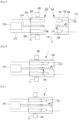
- connection assembly 1 is shown schematically in figure 1 .
- This connection assembly comprises a connector 100 configured so as to be coupled to a mating connector 200, parallel to a coupling direction A.
- the connector 100 is a cable connector.
- the mating connector 200 is a receptacle configured so as to be installed on a wall 300 through which it passes. According to this example, the connector 100 is a female connector and the mating connector 200 is a male connector.
- the connector 100 comprises in particular a housing 102, power contacts 104, a conductive component 106, a shielding element such as a shielding cage 108 and a passive detection device 110 for passively detecting potential overheating.
- the housing 102 of the connector 100 is formed of one or more elements made of insulating plastic.
- the power contacts 104 are housed in chambers formed in the housing 102. These are female power contacts that are each respectively electrically connected to a cable 112.
- the conductive component 106 is an electrical contact blade with two flexible contact tabs 114 that are electrically connected to one another so as to form a shunt.
- the shielding cage 108 consists of one or more metal sheets made of electrically conductive material.
- the shielding cage 108 is configured so as to at least partially screen the electromagnetic waves generated by the flow of high currents through the connection assembly 1.
- the shielding cage 108 is in electrical contact with the individual shielding braids of the cables 112 (and/or with a shielding sheath common to multiple cables 112, this configuration not being shown).
- the mating connector 200 comprises in particular a housing 202, power contacts 204, signal contacts 206 and a shielding element such as a shielding cage 208.
- the housing 202 of the mating connector 200 is formed of one or more elements made of insulating plastic.
- the power contacts 204 are housed in chambers formed in the housing 202. These are male power contacts that are each respectively electrically connected to a cable 212.
- the signal contacts 206 are each respectively connected to an interlock control circuit 210 by electrical wires 214. The signal contacts 206 and the electrical wires 214 are therefore integrated in a first low-voltage electrical line.
- the interlock control circuit 210 controls the opening and the closure of the high-voltage circuit comprising the power contacts 204 of the mating connector 200.
- the shielding cage 208 consists of one or more metal sheets made of electrically conductive material.
- the shielding cage 208 is configured so as to at least partially screen the electromagnetic waves generated by the flow of high currents through the connection assembly 1.
- the shielding cage is in electrical contact with the individual shielding braids of the cables 212 (and/or with a shielding sheath common to multiple cables 112, this configuration not being shown).
- the shielding cage 208 is also in electrical contact with the wall 300, which is itself connected to the ground of the vehicle.
- the shielding cages 108, 208 are therefore intended to participate in a second low-voltage electrical line connected to the ground of the vehicle.
- the shielding cages 108, 208 are integrated in a low-voltage electrical line that is not connected to the ground of the vehicle.
- the male power contacts 204 and female power contacts 104 are connected in pairs
- the signal contacts 206 are connected to the conductive component 106, thereby closing the loop of the interlock control circuit 210
- the respective shielding cages 108, 208 of the connector 100 and mating connector 200 are in electrical contact with one another (thereby also potentially making it possible to connect the cage of the connector to the ground of the vehicle).
- the interlock control circuit 210 controls and triggers the supply of power to the power contacts 204 ( Figure 2 ). Without overheating, the detection device 110 electrically insulates the conductive component 106 from the shielding cage 108 of the connector 100. The first and second low-voltage electrical lines are isolated from one another.
- the detection device 110 deforms and connects the conductive component 106 to the shielding cage 108 of the connector 100 ( Figure 3 ).
- the interlock control circuit 210 detects a variation in the signal measured on the loop of the interlock control circuit 210. For example, before overheating, the interlock control circuit 210 continuously measures a voltage that corresponds to a resistance R, representing the resistance of the electrical wires 214, of the signal contacts 206 and of the conductive component 106, and the contact resistances between these various elements.
- the interlock control circuit 210 measures a voltage that corresponds to a resistance R', representing the resistance of one of the electrical wires 214, of one of the signal contacts 206, of part of the conductive component 106 and of the detection device 110, and the contact resistances between these various elements.
- R' representing the resistance of one of the electrical wires 214, of one of the signal contacts 206, of part of the conductive component 106 and of the detection device 110, and the contact resistances between these various elements.
- the variation between R and R' is enough to signal a change of configuration in the detection device 110, this change resulting from overheating in the connection assembly 1.
- grounding the interlock control circuit renders it inoperative, thereby possibly causing the disconnection of the supply of power to the power contacts 104, 204.
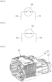
- the change of configuration of the detection device 110 is shown schematically in Figures 4 and 5 .
- Figure 4 before overheating, there is no connection (practically infinite resistance in the detection device 110) between the loop 216 of the interlock control circuit 210 and the line 116 incorporating the shielding cage 108 (the first low-voltage electrical line 116 and second low-voltage electrical line 216 are isolated from one another).
- Figure 5 after overheating, the detection device 110 connects the loop 216 of the interlock control circuit 210 and the line 116 incorporating the shielding cage 108 (the first low-voltage electrical line 116 and second low-voltage electrical line 216 are connected to one another).
- FIG. 1 One particular exemplary embodiment of a connector 100 is described with reference to Figures 6 to 9 ( Figure 1 ).
- the connector 100 comprises an internal housing element 120, an external housing element 130, two shielding metal sheets 141, 142 forming the shielding cage 108, a conductive component 106, a detection device 110, and a coupling assistance device 150.
- the shielding metal sheets 141, 142 are inserted between the internal housing element 120 and external housing element 130.
- the detection device 110 comprises an electrically conductive element 160 and an electrically insulating element 170 ( Figure 8 ).
- the electrically conductive element 160 is a helical spring.
- the axial force Fx supplied by the electrically conductive element 160 is for example between 1 and 50 newtons.
- the electrically conductive element 160 is installed in a support 180.
- the support 180 is integral with the electrically insulating element 170, and consists of a material having a melting temperature of between 125°C and 200°C.
- said melting temperature is equal to or close to 180°C.
- this polymer material is a polypropylene, a polyethylene or an epoxy.
- the support 180 and the electrically insulating element 170 form one part having a U-shaped cross section.
- One of the branches of the U comprises an opening 182 for the passage of the electrically conductive element 160 (see Figure 7 ).
- the other branch of the U corresponds to the insulating element 170 on which the electrically conductive element 160 bears and exerts a pressure corresponding to the axial force Fx.
- the support 180 When the detection device 110 is installed in the connector 100, the support 180 is surrounded in a recess formed in the internal housing element 120 of the connector 100, such that the electrically conductive element 160 is in electrical contact, via one of its axial ends, with the conductive component 106 (and more particularly one of its flexible tabs 114) and is insulated, at the other axial end, from the shielding metal sheet 141 by the insulating element 170 ( Figure 9 ).
- the electrically insulating element 170 is therefore inserted between the electrically conductive element 160 and the shielding metal sheet 141.
- the thickness E of the electrically insulating element 170 thus inserted is for example between 0.5 millimetres and 2 millimetres. For example, this thickness E is equal to or close to 0.8 millimetres.
- the insulating element softens and, under the effect of the pressure exerted by the electrically conductive element 160 on the electrically insulating element 170, the electrically conductive element 160 passes through the electrically insulating element 170 and establishes electrical contact with the shielding metal sheet 141.
- an electrically insulating element 170 similar to the one described above may be inserted between the electrically conductive element 160 and the conductive component 106.
- the electrically insulating element 170 is inserted between the electrically conductive element 160 on one side and between the electrically conductive element 160 and the shielding cage 108 on another side.
- the shielding element may be formed of something other than a metal sheet (for example a housing element on which a conductive layer is deposited).
- the electrically conductive element may be other than a spring (for example a component that expands under the effect of heat).
- the detection device may be installed in the mating connector 200, rather than in the connector 100, or else in the connector 100 and the mating connector 200.
- connection device 1 may be designed to connect a single cable or more than two cables.
- the connector and mating connector do not necessarily have shielding and/or are not necessarily connected to an interlock control circuit.
- the low-voltage lines may be dedicated lines or lines configured so as to transmit a signal.
Landscapes
- Engineering & Computer Science (AREA)
- Chemical & Material Sciences (AREA)
- Combustion & Propulsion (AREA)
- Microelectronics & Electronic Packaging (AREA)
- Details Of Connecting Devices For Male And Female Coupling (AREA)
Claims (11)
- Elektrischer Steckverbinder (100) mit- ein Gehäuse (102), das mindestens eine erste leitende Komponente (106), die so konfiguriert ist, dass sie in eine erste elektrische Niederspannungsleitung integriert wird, und mindestens eine zweite leitende Komponente (108), die so konfiguriert ist, dass sie in eine zweite elektrische Niederspannungsleitung integriert wird, aufnimmt,- mindestens ein elektrisch isolierendes Element (170) und mindestens ein elektrisch leitendes Element (160), die zwischen dem ersten leitenden Bauteil (106) und dem zweiten leitenden Bauteil (108) eingefügt sind,das elektrisch isolierende Element (170) aus einem Material mit einer Schmelztemperatur besteht, die kleiner oder gleich der Schmelztemperatur mindestens eines der das Gehäuse (102) bildenden Materialien ist, unddadurch gekennzeichnet, dass- das elektrisch leitende Element (160) eine elastische Kraft auf das elektrisch isolierende Element (170) ausübt, die geeignet ist, das elektrisch isolierende Element (170) zu verformen, wenn das elektrisch isolierende Element (170) eine Temperatur hat, die größer oder gleich seiner Schmelztemperatur ist, und eine elektrische Verbindung zwischen der ersten leitenden Komponente (106) und der zweiten leitenden Komponente (108) herstellt.
- Elektrischer Steckverbinder (100) nach Anspruch 1, wobei das erste leitende Bauteil (106) so ausgebildet ist, dass es über die erste Niederspannungsleitung mit einer Verriegelungssteuerschaltung (210) eines Hochspannungsstromkreises verbunden ist.
- Elektrischer Steckverbinder (100) nach Anspruch 1 oder 2, wobei die zweite leitende Komponente ein am Gehäuse (102) angebrachtes Abschirmelement (108) ist.
- Elektrischer Verbinder (100) nach Anspruch 2 und 3 in Kombination, wobei das elektrisch isolierende Element (170) zwischen dem elektrisch leitenden Element (160) und dem Abschirmelement (108) eingesetzt ist.
- Elektrischer Verbinder (100) nach einem der vorhergehenden Ansprüche, wobei das elektrisch isolierende Element (170) und das elektrisch leitende Element (160) zusammen in einer passiven Erfassungsvorrichtung (110) integriert sind, die in einer Aussparung im Gehäuse (102) installiert ist.
- Elektrischer Verbinder (100) nach einem der vorhergehenden Ansprüche, wobei das elektrisch leitende Element (160) eine Kraft zwischen 1 und 50 Newton auf das elektrisch isolierende Element (170) ausübt.
- Elektrischer Verbinder (100) nach einem der vorhergehenden Ansprüche, wobei das elektrisch leitende Element (160) eine Schraubenfeder ist, die zwischen dem elektrisch isolierenden Element (170) und mindestens einer der ersten (106) und zweiten (108) leitenden Komponenten zusammengedrückt wird.
- Verbindungsanordnung (1), die einen Verbinder (100) nach einem der vorhergehenden Ansprüche und einen Gegenverbinder (200) umfasst, der ein Gehäuse (202) umfasst, das Signalkontakte (206) beherbergt, die so konfiguriert sind, dass sie in die erste Niederspannungsleitung integriert werden, wobei diese Signalkontakte (206) mit der ersten leitenden Komponente (106) verbunden sind, wenn der Verbinder (100) und der Gegenverbinder (200) gekoppelt sind.
- Verfahren zum Erkennen von Überhitzung in einer Verbindungsbaugruppe (1), die einen elektrischen Steckverbinder (100) nach Anspruch 1 umfasst, wobei das Isolierelement (170) aus Kunststoff hergestellt ist, der aus einem Material mit einer Schmelztemperatur besteht,
dadurch gekennzeichnet, dass die Verformung des elektrisch isolierenden Elements (170) unter der Beanspruchung durch ein elektrisch leitendes Element (160) verwendet wird, wenn das elektrisch isolierende Element (170) eine Temperatur aufweist, die größer oder gleich seiner Schmelztemperatur ist, um eine elektrische Verbindung zwischen dem mindestens einen ersten leitenden Bauteil (106) und dem mindestens einen zweiten leitenden Bauteil (108) herzustellen, wobei die Herstellung dieser Verbindung eine Änderung der Spannung auf der ersten Niederspannungsleitung und/oder der zweiten Niederspannungsleitung erzeugt, die ein Signal zur Erfassung einer Überhitzung darstellt. - Verfahren nach Anspruch 9, umfassend einen Vorgang des Sammelns eines Signals durch Vornahme einer Reihe von elektrischen Messungen an der ersten Niederspannungsleitung, ferner umfassend einen Vorgang des Überwachens im Laufe der Zeit, ob das im Verlauf der Reihe von an der ersten Niederspannungsleitung vorgenommenen elektrischen Messungen gesammelte Signal nach einer Verbindung der ersten Niederspannungsleitung mit der zweiten Niederspannungsleitung eine Veränderung erfährt, wobei diese Verbindung die Folge der Verformung des elektrisch isolierenden Elements (170) ist.
- Verfahren nach Anspruch 9 oder 10, umfassend einen Vorgang, bei dem eine erste leitende Komponente (106) mit einer Verriegelungssteuerungsschaltung (210) einer Hochspannungsschaltung verbunden wird und die Veränderung des Signals nach einer Verbindung der ersten leitenden Komponente (106) mit einem Abschirmelement (108) des Verbinders (100) über das elektrisch leitende Element (160) erfolgt.
Applications Claiming Priority (1)
| Application Number | Priority Date | Filing Date | Title |
|---|---|---|---|
| FR2102085A FR3120481B1 (fr) | 2021-03-03 | 2021-03-03 | Détection passive de la surchauffe dans un connecteur de puissance |
Publications (2)
| Publication Number | Publication Date |
|---|---|
| EP4054024A1 EP4054024A1 (de) | 2022-09-07 |
| EP4054024B1 true EP4054024B1 (de) | 2025-01-08 |
Family
ID=77710780
Family Applications (1)
| Application Number | Title | Priority Date | Filing Date |
|---|---|---|---|
| EP22159791.7A Active EP4054024B1 (de) | 2021-03-03 | 2022-03-02 | Passive detektion von überhitzung in einem leistungsverbinder |
Country Status (4)
| Country | Link |
|---|---|
| US (1) | US11799250B2 (de) |
| EP (1) | EP4054024B1 (de) |
| CN (1) | CN115036760B (de) |
| FR (1) | FR3120481B1 (de) |
Family Cites Families (23)
| Publication number | Priority date | Publication date | Assignee | Title |
|---|---|---|---|---|
| US4075596A (en) * | 1976-08-23 | 1978-02-21 | Emerson Electric Co. | Sealed casing for a thermally actuable electrical switch |
| US4189697A (en) * | 1977-09-09 | 1980-02-19 | Nifco Inc. | Thermal cut-off fuse |
| US4356469A (en) * | 1980-11-20 | 1982-10-26 | Hilliard Dozier | Electrical terminal with thermal interrupter |
| CN2133976Y (zh) * | 1992-04-04 | 1993-05-19 | 台康资讯股份有限公司 | 用户保安器单体 |
| DE4437122C2 (de) * | 1994-10-01 | 1996-07-18 | Krone Ag | Überspannungsschutzstecker |
| JP4471203B2 (ja) * | 2003-10-28 | 2010-06-02 | エヌイーシー ショット コンポーネンツ株式会社 | 感温ペレット型温度ヒューズおよび感温ペレットの製造方法 |
| JP4583228B2 (ja) * | 2005-04-18 | 2010-11-17 | エヌイーシー ショット コンポーネンツ株式会社 | 感温ペレット型温度ヒューズ |
| JP6389603B2 (ja) * | 2013-12-02 | 2018-09-12 | デクセリアルズ株式会社 | スイッチ素子、スイッチ回路、及び警報回路 |
| KR101435955B1 (ko) * | 2014-04-23 | 2014-09-02 | 동양전자 주식회사 | 감온 펠릿형 온도 퓨즈 |
| KR20160134492A (ko) * | 2015-05-13 | 2016-11-23 | 조인셋 주식회사 | 일체형 복합 안전장치 |
| US20160336136A1 (en) * | 2015-05-13 | 2016-11-17 | Joinset Co., Ltd. | Integral complex safety apparatus |
| CN205543545U (zh) * | 2016-01-05 | 2016-08-31 | 征泰电子有限公司 | 过热自动断电插座 |
| KR101753635B1 (ko) * | 2016-05-25 | 2017-07-19 | 동양전자 주식회사 | 감온 펠릿형 온도 퓨즈 |
| CN107437478A (zh) * | 2016-05-25 | 2017-12-05 | 东洋电子株式会社 | 热敏颗粒型热熔断器 |
| KR101916851B1 (ko) * | 2017-04-26 | 2018-11-08 | 동양전자(주) | 감온 펠릿형 온도 퓨즈 |
| US10566164B2 (en) * | 2017-04-27 | 2020-02-18 | Manufacturing Networks Incorporated (MNI) | Temperature-triggered fuse device and method of production thereof |
| WO2019054437A1 (ja) * | 2017-09-14 | 2019-03-21 | ショット日本株式会社 | 感温ペレット型温度ヒューズ |
| CN109273894B (zh) | 2018-09-26 | 2020-06-05 | 立讯精密工业(昆山)有限公司 | 一种高压连接器 |
| US11456141B2 (en) * | 2018-10-19 | 2022-09-27 | Dong-Yang Electronics Co., Ltd. | Temperature sensitive pellet type thermal fuse |
| CN111105964B (zh) * | 2018-10-25 | 2022-07-29 | 东洋电子株式会社 | 温敏粒子型温度保险丝 |
| CN209802531U (zh) | 2019-03-04 | 2019-12-17 | 诺莱德(上海)汽车科技有限公司 | 一种新型高压连接器温度监测装置 |
| CN209802529U (zh) | 2019-04-02 | 2019-12-17 | 诺莱德(上海)汽车科技有限公司 | 一种高压连接器温度监测装置 |
| CN111854992A (zh) | 2020-06-24 | 2020-10-30 | 浙江莱尼新材料科技有限公司 | 一种高压连接器温度监测装置 |
-
2021
- 2021-03-03 FR FR2102085A patent/FR3120481B1/fr active Active
-
2022
- 2022-03-02 EP EP22159791.7A patent/EP4054024B1/de active Active
- 2022-03-03 US US17/685,754 patent/US11799250B2/en active Active
- 2022-03-03 CN CN202210208030.6A patent/CN115036760B/zh active Active
Also Published As
| Publication number | Publication date |
|---|---|
| FR3120481A1 (fr) | 2022-09-09 |
| FR3120481B1 (fr) | 2023-07-14 |
| CN115036760A (zh) | 2022-09-09 |
| US20220285891A1 (en) | 2022-09-08 |
| CN115036760B (zh) | 2025-06-10 |
| EP4054024A1 (de) | 2022-09-07 |
| US11799250B2 (en) | 2023-10-24 |
Similar Documents
| Publication | Publication Date | Title |
|---|---|---|
| EP2556567B1 (de) | Elektrisches verbindersystem | |
| US10682916B2 (en) | Thermal management of electric vehicle coupler contacts | |
| EP3246997B1 (de) | Elektrisches verbindersystem | |
| US10957894B2 (en) | Battery bus bar module | |
| EP3116075B1 (de) | Elektrischer steckverbinder für ein sicherheitsrückhaltesystem | |
| CN108231616B (zh) | 电压检测构造和电压检测模块 | |
| US12142881B2 (en) | Charging socket with interface | |
| CN109037506B (zh) | 电池组 | |
| CN113922138B (zh) | 一种扁带式连接机构、电能传输装置及机动车辆 | |
| WO2020197406A1 (en) | Circuit board for an electric vehicle charging station | |
| WO2018011690A1 (en) | Connector assembly for a battery system | |
| CN113922123A (zh) | 一种高压连接机构、电能传输装置及机动车辆 | |
| CN217215197U (zh) | 一种高压连接机构、电能传输装置及机动车辆 | |
| CN104779361A (zh) | 用于导电连接和电子监视多个电池组电池的电缆束 | |
| EP4054024A1 (de) | Passive detektion von überhitzung in einem leistungsverbinder | |
| EP4099519B1 (de) | Stecker- und buchsenstromanschlussanordnung, buchen- und steckerstromanschluss | |
| CN111129621B (zh) | 汽车动力电池信号采集线束 | |
| CN1241048A (zh) | 无帽电气插孔接头 | |
| US20190089091A1 (en) | Electrical connector having an arc suppression element | |
| EP3389148B1 (de) | Elektrosteckverbinderanordnung | |
| EP3849021B1 (de) | Spleissverbinderanordnung und verfahren zur montage einer spleissverbinderanordnung | |
| CN210897654U (zh) | 电连接件、电连接组件及电池包电连接结构 | |
| CN116194326A (zh) | 插接连接元件以及用于监控插接连接元件的装置 | |
| HK40098787A (zh) | 保险元件和插塞连接器 | |
| CN115133469A (zh) | 保护装置、高压线缆、高压车载电网和机动车 |
Legal Events
| Date | Code | Title | Description |
|---|---|---|---|
| PUAI | Public reference made under article 153(3) epc to a published international application that has entered the european phase |
Free format text: ORIGINAL CODE: 0009012 |
|
| STAA | Information on the status of an ep patent application or granted ep patent |
Free format text: STATUS: THE APPLICATION HAS BEEN PUBLISHED |
|
| AK | Designated contracting states |
Kind code of ref document: A1 Designated state(s): AL AT BE BG CH CY CZ DE DK EE ES FI FR GB GR HR HU IE IS IT LI LT LU LV MC MK MT NL NO PL PT RO RS SE SI SK SM TR |
|
| STAA | Information on the status of an ep patent application or granted ep patent |
Free format text: STATUS: REQUEST FOR EXAMINATION WAS MADE |
|
| 17P | Request for examination filed |
Effective date: 20230221 |
|
| RAP3 | Party data changed (applicant data changed or rights of an application transferred) |
Owner name: APTIV TECHNOLOGIES LIMITED |
|
| RBV | Designated contracting states (corrected) |
Designated state(s): AL AT BE BG CH CY CZ DE DK EE ES FI FR GB GR HR HU IE IS IT LI LT LU LV MC MK MT NL NO PL PT RO RS SE SI SK SM TR |
|
| RIC1 | Information provided on ipc code assigned before grant |
Ipc: H01R 13/53 20060101ALN20240723BHEP Ipc: H01H 37/76 20060101ALI20240723BHEP Ipc: H01R 13/713 20060101AFI20240723BHEP |
|
| GRAP | Despatch of communication of intention to grant a patent |
Free format text: ORIGINAL CODE: EPIDOSNIGR1 |
|
| STAA | Information on the status of an ep patent application or granted ep patent |
Free format text: STATUS: GRANT OF PATENT IS INTENDED |
|
| RAP1 | Party data changed (applicant data changed or rights of an application transferred) |
Owner name: APTIV TECHNOLOGIES AG |
|
| INTG | Intention to grant announced |
Effective date: 20241001 |
|
| RAP3 | Party data changed (applicant data changed or rights of an application transferred) |
Owner name: APTIV TECHNOLOGIES AG |
|
| GRAS | Grant fee paid |
Free format text: ORIGINAL CODE: EPIDOSNIGR3 |
|
| GRAA | (expected) grant |
Free format text: ORIGINAL CODE: 0009210 |
|
| STAA | Information on the status of an ep patent application or granted ep patent |
Free format text: STATUS: THE PATENT HAS BEEN GRANTED |
|
| P01 | Opt-out of the competence of the unified patent court (upc) registered |
Free format text: CASE NUMBER: APP_62759/2024 Effective date: 20241126 |
|
| AK | Designated contracting states |
Kind code of ref document: B1 Designated state(s): AL AT BE BG CH CY CZ DE DK EE ES FI FR GB GR HR HU IE IS IT LI LT LU LV MC MK MT NL NO PL PT RO RS SE SI SK SM TR |
|
| REG | Reference to a national code |
Ref country code: GB Ref legal event code: FG4D |
|
| REG | Reference to a national code |
Ref country code: CH Ref legal event code: EP |
|
| REG | Reference to a national code |
Ref country code: DE Ref legal event code: R096 Ref document number: 602022009459 Country of ref document: DE |
|
| REG | Reference to a national code |
Ref country code: IE Ref legal event code: FG4D |
|
| PGFP | Annual fee paid to national office [announced via postgrant information from national office to epo] |
Ref country code: AT Payment date: 20250417 Year of fee payment: 4 |
|
| REG | Reference to a national code |
Ref country code: LT Ref legal event code: MG9D |
|
| REG | Reference to a national code |
Ref country code: NL Ref legal event code: MP Effective date: 20250108 |
|
| REG | Reference to a national code |
Ref country code: AT Ref legal event code: MK05 Ref document number: 1758959 Country of ref document: AT Kind code of ref document: T Effective date: 20250108 |
|
| PG25 | Lapsed in a contracting state [announced via postgrant information from national office to epo] |
Ref country code: NL Free format text: LAPSE BECAUSE OF FAILURE TO SUBMIT A TRANSLATION OF THE DESCRIPTION OR TO PAY THE FEE WITHIN THE PRESCRIBED TIME-LIMIT Effective date: 20250108 |
|
| PG25 | Lapsed in a contracting state [announced via postgrant information from national office to epo] |
Ref country code: RS Free format text: LAPSE BECAUSE OF FAILURE TO SUBMIT A TRANSLATION OF THE DESCRIPTION OR TO PAY THE FEE WITHIN THE PRESCRIBED TIME-LIMIT Effective date: 20250408 |
|
| PG25 | Lapsed in a contracting state [announced via postgrant information from national office to epo] |
Ref country code: PL Free format text: LAPSE BECAUSE OF FAILURE TO SUBMIT A TRANSLATION OF THE DESCRIPTION OR TO PAY THE FEE WITHIN THE PRESCRIBED TIME-LIMIT Effective date: 20250108 |
|
| PG25 | Lapsed in a contracting state [announced via postgrant information from national office to epo] |
Ref country code: ES Free format text: LAPSE BECAUSE OF FAILURE TO SUBMIT A TRANSLATION OF THE DESCRIPTION OR TO PAY THE FEE WITHIN THE PRESCRIBED TIME-LIMIT Effective date: 20250108 |
|
| PG25 | Lapsed in a contracting state [announced via postgrant information from national office to epo] |
Ref country code: NO Free format text: LAPSE BECAUSE OF FAILURE TO SUBMIT A TRANSLATION OF THE DESCRIPTION OR TO PAY THE FEE WITHIN THE PRESCRIBED TIME-LIMIT Effective date: 20250408 Ref country code: IS Free format text: LAPSE BECAUSE OF FAILURE TO SUBMIT A TRANSLATION OF THE DESCRIPTION OR TO PAY THE FEE WITHIN THE PRESCRIBED TIME-LIMIT Effective date: 20250508 |
|
| PG25 | Lapsed in a contracting state [announced via postgrant information from national office to epo] |
Ref country code: HR Free format text: LAPSE BECAUSE OF FAILURE TO SUBMIT A TRANSLATION OF THE DESCRIPTION OR TO PAY THE FEE WITHIN THE PRESCRIBED TIME-LIMIT Effective date: 20250108 |
|
| PG25 | Lapsed in a contracting state [announced via postgrant information from national office to epo] |
Ref country code: LV Free format text: LAPSE BECAUSE OF FAILURE TO SUBMIT A TRANSLATION OF THE DESCRIPTION OR TO PAY THE FEE WITHIN THE PRESCRIBED TIME-LIMIT Effective date: 20250108 Ref country code: PT Free format text: LAPSE BECAUSE OF FAILURE TO SUBMIT A TRANSLATION OF THE DESCRIPTION OR TO PAY THE FEE WITHIN THE PRESCRIBED TIME-LIMIT Effective date: 20250508 |
|
| PG25 | Lapsed in a contracting state [announced via postgrant information from national office to epo] |
Ref country code: GR Free format text: LAPSE BECAUSE OF FAILURE TO SUBMIT A TRANSLATION OF THE DESCRIPTION OR TO PAY THE FEE WITHIN THE PRESCRIBED TIME-LIMIT Effective date: 20250409 Ref country code: BG Free format text: LAPSE BECAUSE OF FAILURE TO SUBMIT A TRANSLATION OF THE DESCRIPTION OR TO PAY THE FEE WITHIN THE PRESCRIBED TIME-LIMIT Effective date: 20250108 |
|
| PG25 | Lapsed in a contracting state [announced via postgrant information from national office to epo] |
Ref country code: AT Free format text: LAPSE BECAUSE OF FAILURE TO SUBMIT A TRANSLATION OF THE DESCRIPTION OR TO PAY THE FEE WITHIN THE PRESCRIBED TIME-LIMIT Effective date: 20250108 |
|
| PG25 | Lapsed in a contracting state [announced via postgrant information from national office to epo] |
Ref country code: SE Free format text: LAPSE BECAUSE OF FAILURE TO SUBMIT A TRANSLATION OF THE DESCRIPTION OR TO PAY THE FEE WITHIN THE PRESCRIBED TIME-LIMIT Effective date: 20250108 |
|
| PG25 | Lapsed in a contracting state [announced via postgrant information from national office to epo] |
Ref country code: SM Free format text: LAPSE BECAUSE OF FAILURE TO SUBMIT A TRANSLATION OF THE DESCRIPTION OR TO PAY THE FEE WITHIN THE PRESCRIBED TIME-LIMIT Effective date: 20250108 |
|
| REG | Reference to a national code |
Ref country code: DE Ref legal event code: R097 Ref document number: 602022009459 Country of ref document: DE |
|
| PG25 | Lapsed in a contracting state [announced via postgrant information from national office to epo] |
Ref country code: DK Free format text: LAPSE BECAUSE OF FAILURE TO SUBMIT A TRANSLATION OF THE DESCRIPTION OR TO PAY THE FEE WITHIN THE PRESCRIBED TIME-LIMIT Effective date: 20250108 |
|
| PG25 | Lapsed in a contracting state [announced via postgrant information from national office to epo] |
Ref country code: MC Free format text: LAPSE BECAUSE OF FAILURE TO SUBMIT A TRANSLATION OF THE DESCRIPTION OR TO PAY THE FEE WITHIN THE PRESCRIBED TIME-LIMIT Effective date: 20250108 |
|
| PG25 | Lapsed in a contracting state [announced via postgrant information from national office to epo] |
Ref country code: CZ Free format text: LAPSE BECAUSE OF FAILURE TO SUBMIT A TRANSLATION OF THE DESCRIPTION OR TO PAY THE FEE WITHIN THE PRESCRIBED TIME-LIMIT Effective date: 20250108 Ref country code: EE Free format text: LAPSE BECAUSE OF FAILURE TO SUBMIT A TRANSLATION OF THE DESCRIPTION OR TO PAY THE FEE WITHIN THE PRESCRIBED TIME-LIMIT Effective date: 20250108 |
|
| PG25 | Lapsed in a contracting state [announced via postgrant information from national office to epo] |
Ref country code: RO Free format text: LAPSE BECAUSE OF FAILURE TO SUBMIT A TRANSLATION OF THE DESCRIPTION OR TO PAY THE FEE WITHIN THE PRESCRIBED TIME-LIMIT Effective date: 20250108 |
|
| REG | Reference to a national code |
Ref country code: CH Ref legal event code: H13 Free format text: ST27 STATUS EVENT CODE: U-0-0-H10-H13 (AS PROVIDED BY THE NATIONAL OFFICE) Effective date: 20251024 |
|
| PG25 | Lapsed in a contracting state [announced via postgrant information from national office to epo] |
Ref country code: SK Free format text: LAPSE BECAUSE OF FAILURE TO SUBMIT A TRANSLATION OF THE DESCRIPTION OR TO PAY THE FEE WITHIN THE PRESCRIBED TIME-LIMIT Effective date: 20250108 |
|
| PLBE | No opposition filed within time limit |
Free format text: ORIGINAL CODE: 0009261 |
|
| STAA | Information on the status of an ep patent application or granted ep patent |
Free format text: STATUS: NO OPPOSITION FILED WITHIN TIME LIMIT |
|
| PG25 | Lapsed in a contracting state [announced via postgrant information from national office to epo] |
Ref country code: LU Free format text: LAPSE BECAUSE OF NON-PAYMENT OF DUE FEES Effective date: 20250302 |
|
| REG | Reference to a national code |
Ref country code: BE Ref legal event code: MM Effective date: 20250331 |
|
| 26N | No opposition filed |
Effective date: 20251009 |
|
| PG25 | Lapsed in a contracting state [announced via postgrant information from national office to epo] |
Ref country code: BE Free format text: LAPSE BECAUSE OF NON-PAYMENT OF DUE FEES Effective date: 20250331 |
|
| PG25 | Lapsed in a contracting state [announced via postgrant information from national office to epo] |
Ref country code: CH Free format text: LAPSE BECAUSE OF NON-PAYMENT OF DUE FEES Effective date: 20250331 |
|
| PG25 | Lapsed in a contracting state [announced via postgrant information from national office to epo] |
Ref country code: IE Free format text: LAPSE BECAUSE OF NON-PAYMENT OF DUE FEES Effective date: 20250302 |
|
| PG25 | Lapsed in a contracting state [announced via postgrant information from national office to epo] |
Ref country code: IT Free format text: LAPSE BECAUSE OF FAILURE TO SUBMIT A TRANSLATION OF THE DESCRIPTION OR TO PAY THE FEE WITHIN THE PRESCRIBED TIME-LIMIT Effective date: 20250108 |
|
| PGFP | Annual fee paid to national office [announced via postgrant information from national office to epo] |
Ref country code: GB Payment date: 20260204 Year of fee payment: 5 |
|
| PGFP | Annual fee paid to national office [announced via postgrant information from national office to epo] |
Ref country code: DE Payment date: 20260223 Year of fee payment: 5 |
|
| PGFP | Annual fee paid to national office [announced via postgrant information from national office to epo] |
Ref country code: FR Payment date: 20260205 Year of fee payment: 5 |