EP4053974B1 - Battery module comprising cooling member, battery pack comprising same battery module, and electronic device - Google Patents
Battery module comprising cooling member, battery pack comprising same battery module, and electronic device Download PDFInfo
- Publication number
- EP4053974B1 EP4053974B1 EP21807741.0A EP21807741A EP4053974B1 EP 4053974 B1 EP4053974 B1 EP 4053974B1 EP 21807741 A EP21807741 A EP 21807741A EP 4053974 B1 EP4053974 B1 EP 4053974B1
- Authority
- EP
- European Patent Office
- Prior art keywords
- upper frame
- battery module
- battery
- cooling member
- lower frame
- Prior art date
- Legal status (The legal status is an assumption and is not a legal conclusion. Google has not performed a legal analysis and makes no representation as to the accuracy of the status listed.)
- Active
Links
Images


Classifications
-
- H—ELECTRICITY
- H01—ELECTRIC ELEMENTS
- H01M—PROCESSES OR MEANS, e.g. BATTERIES, FOR THE DIRECT CONVERSION OF CHEMICAL ENERGY INTO ELECTRICAL ENERGY
- H01M10/00—Secondary cells; Manufacture thereof
- H01M10/60—Heating or cooling; Temperature control
- H01M10/61—Types of temperature control
- H01M10/613—Cooling or keeping cold
-
- H—ELECTRICITY
- H01—ELECTRIC ELEMENTS
- H01M—PROCESSES OR MEANS, e.g. BATTERIES, FOR THE DIRECT CONVERSION OF CHEMICAL ENERGY INTO ELECTRICAL ENERGY
- H01M10/00—Secondary cells; Manufacture thereof
- H01M10/60—Heating or cooling; Temperature control
- H01M10/64—Heating or cooling; Temperature control characterised by the shape of the cells
- H01M10/643—Cylindrical cells
-
- H—ELECTRICITY
- H01—ELECTRIC ELEMENTS
- H01M—PROCESSES OR MEANS, e.g. BATTERIES, FOR THE DIRECT CONVERSION OF CHEMICAL ENERGY INTO ELECTRICAL ENERGY
- H01M10/00—Secondary cells; Manufacture thereof
- H01M10/60—Heating or cooling; Temperature control
- H01M10/65—Means for temperature control structurally associated with the cells
- H01M10/655—Solid structures for heat exchange or heat conduction
- H01M10/6554—Rods or plates
-
- H—ELECTRICITY
- H01—ELECTRIC ELEMENTS
- H01M—PROCESSES OR MEANS, e.g. BATTERIES, FOR THE DIRECT CONVERSION OF CHEMICAL ENERGY INTO ELECTRICAL ENERGY
- H01M10/00—Secondary cells; Manufacture thereof
- H01M10/60—Heating or cooling; Temperature control
- H01M10/65—Means for temperature control structurally associated with the cells
- H01M10/655—Solid structures for heat exchange or heat conduction
- H01M10/6556—Solid parts with flow channel passages or pipes for heat exchange
-
- H—ELECTRICITY
- H01—ELECTRIC ELEMENTS
- H01M—PROCESSES OR MEANS, e.g. BATTERIES, FOR THE DIRECT CONVERSION OF CHEMICAL ENERGY INTO ELECTRICAL ENERGY
- H01M10/00—Secondary cells; Manufacture thereof
- H01M10/60—Heating or cooling; Temperature control
- H01M10/62—Heating or cooling; Temperature control specially adapted for specific applications
- H01M10/625—Vehicles
-
- H—ELECTRICITY
- H01—ELECTRIC ELEMENTS
- H01M—PROCESSES OR MEANS, e.g. BATTERIES, FOR THE DIRECT CONVERSION OF CHEMICAL ENERGY INTO ELECTRICAL ENERGY
- H01M2220/00—Batteries for particular applications
- H01M2220/20—Batteries in motive systems, e.g. vehicle, ship, plane
-
- Y—GENERAL TAGGING OF NEW TECHNOLOGICAL DEVELOPMENTS; GENERAL TAGGING OF CROSS-SECTIONAL TECHNOLOGIES SPANNING OVER SEVERAL SECTIONS OF THE IPC; TECHNICAL SUBJECTS COVERED BY FORMER USPC CROSS-REFERENCE ART COLLECTIONS [XRACs] AND DIGESTS
- Y02—TECHNOLOGIES OR APPLICATIONS FOR MITIGATION OR ADAPTATION AGAINST CLIMATE CHANGE
- Y02E—REDUCTION OF GREENHOUSE GAS [GHG] EMISSIONS, RELATED TO ENERGY GENERATION, TRANSMISSION OR DISTRIBUTION
- Y02E60/00—Enabling technologies; Technologies with a potential or indirect contribution to GHG emissions mitigation
- Y02E60/10—Energy storage using batteries
Definitions
- the present invention relates to a battery module including a cooling member, a battery pack including the battery module, and an electrical device, and more particularly, to a battery module with improved manufacturing efficiency and improved cooling efficiency.
- Secondary batteries currently commercialized include nickel cadmium batteries, nickel hydrogen batteries, nickel zinc batteries, lithium secondary batteries and so on.
- the lithium secondary batteries are more highlighted in comparison to nickel-based secondary batteries due to advantages such as free charging and discharging, caused by substantially no memory effect, very low self-discharge rate, and high energy density.
- the lithium secondary battery mainly uses lithium-based oxides and carbonaceous materials as a positive electrode active material and a negative electrode active material, respectively.
- the lithium secondary battery includes an electrode assembly in which a positive electrode plate coated with the positive electrode active material and a negative electrode plate coated with the negative electrode active material are disposed with a separator being interposed therebetween, and an exterior, namely a battery case, hermetically containing the electrode assembly together with an electrolyte.
- the lithium secondary battery may be classified into a can-type secondary battery in which an electrode assembly is embedded in a metal can and a pouch-type secondary battery in which an electrode assembly is embedded in a pouch made of an aluminum laminate sheet, depending on the shape of its exterior.
- a metal can of the can-type secondary battery in which the electrode assembly is embedded may be manufactured in a cylindrical shape.
- the can-type secondary battery may be used to configure a battery module, which includes a module case for accommodating a plurality of secondary batteries and a bus bar configured to electrically connect the plurality of secondary batteries.
- the conventional battery module includes a heatsink to discharge heat generated from the module case including a plurality of secondary batteries to the outside.
- a cooling plate for heat conduction is generally interposed between the module case and a heatsink.
- the cooling plate interposed between the module case and the heatsink may lengthen a heat transfer path and reduce the heat conduction efficiency.
- the cooling plate is welded to the module case and the heatsink, respectively, components are likely to thermally deform.
- a plurality of members should be welded to each other, there is a problem of lowering the manufacturing process efficiency.
- the present invention is designed to solve the problems of the related art, and therefore it is an object of the present invention to provide a battery module, a battery pack, and an electric device comprising the same, with improved manufacturing efficiency and improved cooling efficiency.
- the cooling member is coupled to the upper frame and the upper frame to which the plurality of secondary batteries are mounted and the coolant channel is provided to the lower frame, the plurality of secondary batteries may directly contact the upper surface of the cooling member without any additional heat conductive member interposed therebetween, thereby improving the cooling efficiency.
- the cooling member since the lower frame of the cooling member is configured to be bonded to the other surface of the upper frame, the cooling member may be assembled without a separate fastening member. Accordingly, in the present invention, it is possible to reduce the number of parts and shorten the manufacturing time, compared to the conventional art, thereby reducing the manufacturing cost.
- the bonding strength between the upper frame and the lower frame may be further increased. Accordingly, in the present invention, when an external shock occurs while the battery module is in use, it is possible to further prevent the coolant from leaking through the gap between the upper frame and the lower frame due to a crack generated at the cooling member.
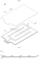
- FIG. 1 is a perspective view schematically showing a battery module according to an embodiment of the present invention.
- FIG. 2 is an exploded perspective view schematically showing components of the battery module according to an embodiment of the present invention.
- the X-axis shown in FIG. 1 refers to a right and left direction
- the Y-axis refers to a front and rear direction
- the Z-axis refers to an upper and lower direction.
- a battery module 200 may include a plurality of secondary batteries 210 and a cooling member 220.
- the secondary battery 210 may be a cylindrical battery cell.
- a negative electrode terminal 211b may be formed at an upper portion (an upper corner portion) of a battery can.
- the cylindrical battery cell may have a battery cap provided at an upper portion thereof, and a positive electrode terminal 211a may be formed at the center of the battery cap.
- the battery can may include an electrode assembly (not shown) accommodated therein.
- the battery can and the battery cap may be electrically insulated from each other. Since the configuration of the cylindrical battery cell is widely known to those skilled in the art at the time of filing of this application, it will not be described in more detail in this specification.
- the plurality of secondary batteries 210 may be disposed to be spaced apart from each other by a distance of 3 mm, for example.
- a plurality of secondary batteries 210 located in one row and a plurality of secondary batteries 210 located in another row may be arranged to be positioned differently in a front and rear direction (X-axis direction).
- the plurality of secondary batteries 210 located in one row and the plurality of secondary batteries 210 located in another row may be arranged to be positioned differently in a left and right direction. That is, the plurality of secondary batteries 210 may be regarded as being arranged in a zigzag pattern in front, rear, left and right directions as a whole.
- the plurality of secondary batteries 210 may be electrically connected in series or in parallel by a bus bar (not shown) having a conductive metal.
- the bus bar may include, for example, at least one of copper, nickel and aluminum.
- the bus bar may be in the form of a wire.
- the bus bar may electrically connect the positive electrode terminals 211a located on the battery cap at the upper portion of the secondary battery 210 (a positive direction of the Z-axis in FIG. 1 ) and/or negative electrode terminals 211b formed on the battery can to each other.
- the cooling member 220 may include an upper frame 221 and a lower frame 226.
- the upper frame 221 may have a plate shape with a predetermined length so that the plurality of secondary batteries 210 may be mounted to one surface (an upper surface) thereof.
- the lower frame 226 may have an upper portion corresponding to the plane size of the upper frame 221.
- the lower frame 226 may be coupled to the other surface of the upper frame 221.
- the lower frame 226 may include a coolant channel D configured so that a coolant flows therethrough.
- the cooling member 220 may have an inlet I and an outlet O.
- the inlet I may be configured to inject a cooled coolant from an external device.
- the outlet O may be configured such that a coolant absorbing heat from the plurality of secondary batteries 210 is discharged toward the external device.
- the coolant channel D may be connected to the inlet I and the outlet O, respectively.
- the coolant channel D may include a moving path configured to protrude relatively downward to form an empty space through which the coolant may flow, and a barrier W configured to protrude upward to partition the moving path.
- the coolant may be water, for example.
- the cooling member 220 is coupled to the upper frame 221 and the upper frame 221 to which the plurality of secondary batteries 210 are mounted and the coolant channel is provided to the lower frame 226, the plurality of secondary batteries 210 may directly contact the upper surface of the cooling member 220 without any additional heat conductive member interposed therebetween, thereby improving the cooling efficiency.
- the upper frame 221 may be manufactured by a pressing method so as not to be susceptible to thermal deformation caused by welding or the like.
- the upper frame 221 may be made of a metal material such as steel, aluminum and stainless steel. That is, since the upper frame 221 is manufactured by a pressing method, thermal deformation may not be severely generated. Accordingly, in the present invention, it is possible to prevent the contact area of the plurality of secondary batteries 210 in contact with one surface of the upper frame 221 from being reduced, since thermal deformation of the upper frame 221 is less generated by the heat generated by charging and discharging of the battery module 200.
- the lower frame 226 may be manufactured by an injection method.
- the lower frame 226 may be made of a plastic material.
- the plastic material may be, for example, an engineering plastic. Since some components of the cooling structure is made of plastic that a lightweight material, it is possible to reduce the weight of the battery module 200.
- FIG. 3 is a vertical sectional view schematically showing the battery module, taken along the line C-C' of FIG. 2 .
- the coolant channel D of the lower frame 226 may have an uneven structure K with a portion 226a protruding toward the upper frame 221 in cross section.
- the portion 226a protruding toward the upper frame 221 may be an upper surface of each of the barrier W of the lower frame 226 and the outer peripheral portion of the lower frame 226.
- the portion 226a of the uneven structure K protruding toward the upper frame 221 may be configured to be bonded to the other surface (a lower surface) of the upper frame 221.
- the bonding may be performed using an adhesive.
- the adhesive is not limited to a specific material and, for example, the adhesive may be a glue or a hot-melt resin.
- the adhesive may include at least one of a polyamide resin, a polyimide resin, an epoxy resin, and an acrylic resin.
- the cooling member 220 since the lower frame 226 of the cooling member 220 is configured to be bonded to the other surface of the upper frame 221, the cooling member 220 may be assembled without a separate fastening member. Accordingly, in the present invention, it is possible to reduce the number of parts and shorten the manufacturing time, compared to the conventional art, thereby reducing the manufacturing cost.
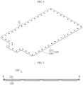
- FIG. 4 is a perspective view schematically showing some components of a battery module according to another embodiment of the present invention.
- the cooling member 220 of FIG. 4 may have a portion in which the upper frame 221 and the lower frame 226 are coupled (joined) by welding.
- the cooling member 220 of FIG. 4 may have a portion J1 in which both side portions of the upper frame 221 and the lower frame 226 are joined to each other by at least one of spot welding, arc welding and laser welding.
- spot welding arc welding
- laser welding it is not limited to welding methods, and any known applicable welding method may be used.
- the bonding strength between the upper frame 221 and the lower frame 226 may be further increased. Accordingly, in the present invention, when an external shock occurs while the battery module 200 is in use, it is possible to further prevent the coolant from leaking through the gap between the upper frame 221 and the lower frame 226 due to a crack generated at the cooling member 220.
- FIG. 5 is a vertical sectional view schematically showing some components of a battery module according to still another embodiment of the present invention.
- the cooling member 220 of FIG. 5 may have a portion in which the upper frame 221 and the lower frame 226 are coupled to each other by mechanical joining.
- both side portions of the upper frame 221 and the lower frame 226 may be coupled to each other by riveting, which is a mechanical joining method.
- the riveting is a process of joining two members to each other by penetrating a rivet R through the upper frame 221 and the lower frame 226, respectively.
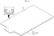
- FIG. 6 is a perspective view schematically showing some components of a battery module according to still another embodiment of the present invention.
- both side portions of the upper frame 221 and the lower frame 226 may have a portion J2 in which the upper frame 221 and the lower frame 226 are coupled to each other using at least one of TOX clinching and clinching.
- a space J indented inward by TOX clinching or clinching may be formed.
- portions of the upper frame 221 and the lower frame 226 may be joined to each other in a state of overlapping with each other by applying a cold forming method.
- the TOX clinching is a process in which portions of the upper frame 221 and the lower frame 226 are plastically deformed in a state of overlapping with each other to be joined.
- both side portions of the upper frame 221 and the lower frame 226 are coupled to each other using a mechanical joining method, the bonding force between the upper frame 221 and the lower frame 226 may be further enhanced. Accordingly, in the present invention, it is possible to further prevent the coolant from leaking through the gap between the upper frame 221 and the lower frame 226 due to a crack generated in the cooling member 220 when an external shock occurs while the battery module 200 is in use.
- FIG. 7 is a perspective view schematically showing a battery module according still another embodiment of the present invention.
- a cooling member 220A of a battery module 200A of FIG. 7 may further include sidewalls 221w provided at both side ends of the upper frame 221, respectively.
- the sidewall 221w may have a shape extending upward from each of both side ends of the upper frame 221 having a plate shape.
- the sidewall 221w may be formed integrally with the upper frame 221.
- the upper frame 221 of the cooling member 220 of the present invention may include a left sidewall 221w and a right sidewall 221w respectively provided at left and right ends in the X direction.
- the sidewall 221w may have a shape elongating in a front and rear direction (Y-axis direction).
- the sidewalls 221w respectively extending upward from both side ends of the upper frame 221 are further provided, it is possible to prevent the cooling member 220 from being bent in a vertical direction. That is, the sidewall 221w may serve as a reinforcing member for reinforcing the rigidity of the cooling member 220 to prevent the cooling member 220 from being bent due to the plurality of secondary batteries 210 mounted on the cooling member 220.
- FIG. 8 is a perspective view schematically showing some components of a battery module according to still another embodiment of the present invention. Also, FIG. 9 is a vertical sectional view schematically showing some components of the battery module of FIG. 8 .
- the cooling member 220 of the battery module of FIG. 8 may further include a clip member 230.
- the clip member 230 may be configured to fix both side ends of the upper frame 221 and the lower frame 226 to each other.
- the clip member 230 may include a body portion 231 and a fixing portion 233.
- the body portion 231 may elongate along one surface of the upper frame 221 and configured to be in close contact with one surface of the upper frame 221.
- the fixing portion 233 may be bent from the body portion 231 to surround both ends of the upper frame 221 and the lower frame 226.
- the body portion 231 of the clip member 230 may have a shape elongating in a left and right direction (X-axis direction) along the upper surface of the upper frame 221.
- the body portion 231 may be in close contact with the upper surface of the upper frame 221 to limit deformation of the upper frame 221 so as to prevent the upper frame 221 from being bent.
- the fixing portion 233 of the clip member 230 may include a first bent portion 233a and a second bent portion 233b to surround both ends of the upper frame 221 and the lower frame 226.
- the first bent portion 233a may be a portion bent downward from left and right ends the body portion 231.
- the second bent portion 233b may be a portion bent inward (toward the center) from a lower end of the first bent portion 233a.
- the body portion 231 of the clip member 230 serves as a reinforcing member for reinforcing rigidity to prevent the cooling member 220 from being bent due to the plurality of secondary batteries 210 mounted on the cooling member 220.
- the fixing portion 233 of the clip member 230 may be bent to surround both side ends of the upper frame 221 and the lower frame 226, thereby preventing both side ends of the upper frame 221 and the lower frame 226 from being separated. Accordingly, in the present invention, by means of the clip member 230, it is possible to further prevent the coolant from leaking through the gap between the upper frame 221 and the lower frame 226 due to a crack generated at the cooling member 220 when an external shock occurs while the battery module 200 is in use.
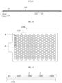
- FIG. 10 is a plan view schematically showing some components of a battery module according to still another embodiment of the present invention. Also, FIG. 11 is a horizontal sectional view schematically showing the battery module, taken along the line A-A' of FIG. 10 .
- a cooling member 220B of FIG. 10 may include a plurality of guide protrusions P provided at on the upper surface of the upper frame 221.
- the guide protrusions P may have a shape protruding from the upper surface of the upper frame 221 toward the secondary batteries 210 (in a positive direction of the Z-axis in FIG. 1 ) to guide mounting locations of the plurality of secondary batteries 210.
- the guide protrusion P may have a circular shape in a plane so as to surround the outer peripheral portion of the lower end of the secondary battery 210.
- one secondary battery 210 may be mounted inside the circular guide protrusion P.
- the plurality of secondary batteries 210 may be easily disposed at correct locations, and the contact area between the upper frame 221 and the plurality of secondary batteries 210 may be increased, thereby effectively enhancing the cooling efficiency of the cooling member.
- a battery pack (not shown) according to an embodiment of the present invention includes at least one battery module 200.
- the battery pack may further include various devices (not shown) for controlling charging and discharging of the battery module 200, for example a battery management system (BMS), a current sensor, and a fuse.
- BMS battery management system
- an electrical device includes at least one battery module 200 described above.
- the electrical device may further include a device housing (not shown) having an accommodation space for accommodating the battery module 200, and a display unit through which a user may check the state of charge of the battery module 200.
- the battery pack according to an embodiment of the present invention may be provided to a vehicle such as an electric vehicle or a hybrid electric vehicle. That is, the vehicle according to an embodiment of the present invention may be equipped with a battery pack including at least one battery module 200 according to an embodiment of the present invention described above, to be mounted in a vehicle body.
- Reference Signs 200 battery module 220: cooling member 221, 226: upper frame, lower frame D: coolant channel K: uneven structure 210: secondary battery 221w: sidewall 230: clip member 231, 233: body portion, fixing portion P: guide protrusion
Landscapes
- Engineering & Computer Science (AREA)
- Manufacturing & Machinery (AREA)
- Chemical & Material Sciences (AREA)
- Chemical Kinetics & Catalysis (AREA)
- Electrochemistry (AREA)
- General Chemical & Material Sciences (AREA)
- Secondary Cells (AREA)
- Battery Mounting, Suspending (AREA)
Applications Claiming Priority (2)
| Application Number | Priority Date | Filing Date | Title |
|---|---|---|---|
| KR1020200061863A KR102888354B1 (ko) | 2020-05-22 | 2020-05-22 | 냉각 부재를 포함하는 배터리 모듈, 및 배터리 모듈을 포함하는 배터리 팩, 및 전자 디바이스 |
| PCT/KR2021/006106 WO2021235784A1 (ko) | 2020-05-22 | 2021-05-14 | 냉각 부재를 포함하는 배터리 모듈, 및 이러한 배터리 모듈을 포함하는 배터리 팩, 및 전자 디바이스 |
Publications (3)
| Publication Number | Publication Date |
|---|---|
| EP4053974A1 EP4053974A1 (en) | 2022-09-07 |
| EP4053974A4 EP4053974A4 (en) | 2023-08-16 |
| EP4053974B1 true EP4053974B1 (en) | 2025-05-07 |
Family
ID=78708603
Family Applications (1)
| Application Number | Title | Priority Date | Filing Date |
|---|---|---|---|
| EP21807741.0A Active EP4053974B1 (en) | 2020-05-22 | 2021-05-14 | Battery module comprising cooling member, battery pack comprising same battery module, and electronic device |
Country Status (10)
| Country | Link |
|---|---|
| US (1) | US12381273B2 (pl) |
| EP (1) | EP4053974B1 (pl) |
| JP (1) | JP7490770B2 (pl) |
| KR (1) | KR102888354B1 (pl) |
| CN (1) | CN114747067B (pl) |
| ES (1) | ES3031304T3 (pl) |
| HU (1) | HUE071821T2 (pl) |
| PL (1) | PL4053974T3 (pl) |
| TW (1) | TWI901683B (pl) |
| WO (1) | WO2021235784A1 (pl) |
Families Citing this family (1)
| Publication number | Priority date | Publication date | Assignee | Title |
|---|---|---|---|---|
| JP2023120534A (ja) * | 2022-02-18 | 2023-08-30 | 株式会社レゾナック | 冷却器の製造方法、冷却器 |
Family Cites Families (32)
| Publication number | Priority date | Publication date | Assignee | Title |
|---|---|---|---|---|
| JPH0917927A (ja) | 1995-06-30 | 1997-01-17 | Copal Co Ltd | ファンモータを備えた冷却装置 |
| DE102008059967B4 (de) * | 2008-12-02 | 2015-02-05 | Daimler Ag | Batterie und Verfahren zur Herstellung einer Batterie mit einer in einem Batteriegehäuse angeordneten Wärmeleitplatte |
| KR101084767B1 (ko) | 2009-10-09 | 2011-11-21 | 삼성에스디아이 주식회사 | 전지팩 |
| TWI445233B (zh) | 2009-10-27 | 2014-07-11 | Ind Tech Res Inst | 具有導熱膠之電池組 |
| DE102010013025A1 (de) | 2010-03-26 | 2011-09-29 | Daimler Ag | Batterie und Verfahren zur Herstellung einer Batterie mit einer in einem Batteriegehäuse angeordneten Kühlplatte |
| JP2012094370A (ja) | 2010-10-27 | 2012-05-17 | Sanyo Electric Co Ltd | 電池モジュール |
| US9638475B2 (en) | 2010-10-29 | 2017-05-02 | Dana Canada Corporation | Heat exchanger and battery unit structure for cooling thermally conductive batteries |
| JP5513445B2 (ja) | 2011-06-08 | 2014-06-04 | 本田技研工業株式会社 | 車両用電源装置 |
| US8999547B2 (en) * | 2011-12-22 | 2015-04-07 | Samsung Sdi Co., Ltd. | Battery module |
| CN103296330A (zh) | 2012-03-01 | 2013-09-11 | 杭州三花研究院有限公司 | 一种电源冷却装置 |
| DE102012005870A1 (de) * | 2012-03-23 | 2013-09-26 | Valeo Klimasysteme Gmbh | Kühlvorrichtung für eine Fahrzeugbatterie sowie Fahrzeugbatterie mit Kühlvorrichtung |
| DE102012012663A1 (de) | 2012-06-23 | 2013-12-24 | Volkswagen Aktiengesellschaft | Gehäuse für eine Betriebseinrichtung, insbesondere für ein Batteriepaket einer Fahrzeugantriebsbatterie |
| KR101781923B1 (ko) * | 2013-02-05 | 2017-09-26 | 한온시스템 주식회사 | 배터리 냉각장치 |
| FR3003938A1 (fr) | 2013-03-29 | 2014-10-03 | Valeo Systemes Thermiques | Plaque d'echange thermique pour gestion thermique de batterie et procede de fabrication associe. |
| KR101589931B1 (ko) * | 2014-01-06 | 2016-01-29 | 희성정밀 주식회사 | 전기 자동차용 배터리 냉각장치 |
| KR102233774B1 (ko) | 2014-02-17 | 2021-03-30 | 삼성에스디아이 주식회사 | 배터리 모듈 |
| DE102014219812A1 (de) * | 2014-09-30 | 2016-03-31 | Robert Bosch Gmbh | Kühlplatte für einen elektrischen Energiespeicher |
| US9412980B2 (en) | 2014-10-17 | 2016-08-09 | Lg Chem, Ltd. | Battery cell assembly |
| US9627724B2 (en) * | 2014-12-04 | 2017-04-18 | Lg Chem, Ltd. | Battery pack having a cooling plate assembly |
| DE102015222775A1 (de) | 2015-11-18 | 2017-05-18 | Mahle International Gmbh | Wärmeübertragerplatte |
| US20170288285A1 (en) | 2016-04-01 | 2017-10-05 | Faraday&Future Inc. | Liquid temperature regulated battery pack for electric vehicles |
| KR102295371B1 (ko) * | 2016-10-13 | 2021-08-31 | 삼성에스디아이 주식회사 | 배터리 모듈 |
| KR20180054064A (ko) | 2016-11-14 | 2018-05-24 | 엘지전자 주식회사 | 배터리 열교환기 및 그를 갖는 배터리 팩 |
| KR101965373B1 (ko) | 2017-01-06 | 2019-04-03 | 주식회사 엘지화학 | 원통형 배터리 모듈 |
| KR101916429B1 (ko) | 2017-03-30 | 2018-11-07 | 엘지전자 주식회사 | 차량용 배터리 팩 및 차량 |
| CN207602744U (zh) | 2017-11-29 | 2018-07-10 | 长城汽车股份有限公司 | 一种电池包及汽车 |
| KR102203250B1 (ko) * | 2017-11-29 | 2021-01-13 | 주식회사 엘지화학 | 엔드 프레임을 구비한 배터리 모듈 |
| US11024901B2 (en) | 2018-01-19 | 2021-06-01 | Hanon Systems | Battery cooling plate with integrated air vents |
| KR102327540B1 (ko) * | 2018-08-31 | 2021-11-17 | (주)엠피에스코리아 | 냉각핀이 구비된 원통 전지용 배터리 팩의 냉각 구조 |
| KR102443098B1 (ko) * | 2018-11-12 | 2022-09-13 | 주식회사 엘지에너지솔루션 | 모듈 하우징을 포함한 배터리 모듈 |
| KR102161467B1 (ko) | 2018-11-26 | 2020-10-05 | 아주대학교산학협력단 | 다차원 데이터의 시각화를 조절하기 위한 방법 및 장치 |
| CN109921144A (zh) | 2019-03-29 | 2019-06-21 | 潍柴动力股份有限公司 | 蓄电池的冷却板及电动汽车 |
-
2020
- 2020-05-22 KR KR1020200061863A patent/KR102888354B1/ko active Active
-
2021
- 2021-05-14 US US17/789,499 patent/US12381273B2/en active Active
- 2021-05-14 JP JP2022527218A patent/JP7490770B2/ja active Active
- 2021-05-14 PL PL21807741.0T patent/PL4053974T3/pl unknown
- 2021-05-14 HU HUE21807741A patent/HUE071821T2/hu unknown
- 2021-05-14 ES ES21807741T patent/ES3031304T3/es active Active
- 2021-05-14 CN CN202180006926.XA patent/CN114747067B/zh active Active
- 2021-05-14 EP EP21807741.0A patent/EP4053974B1/en active Active
- 2021-05-14 WO PCT/KR2021/006106 patent/WO2021235784A1/ko not_active Ceased
- 2021-05-20 TW TW110118258A patent/TWI901683B/zh active
Also Published As
| Publication number | Publication date |
|---|---|
| CN114747067A (zh) | 2022-07-12 |
| ES3031304T3 (en) | 2025-07-07 |
| KR102888354B1 (ko) | 2025-11-18 |
| HUE071821T2 (hu) | 2025-09-28 |
| KR20210144462A (ko) | 2021-11-30 |
| US12381273B2 (en) | 2025-08-05 |
| TW202213855A (zh) | 2022-04-01 |
| PL4053974T3 (pl) | 2025-07-21 |
| EP4053974A4 (en) | 2023-08-16 |
| WO2021235784A1 (ko) | 2021-11-25 |
| US20230040680A1 (en) | 2023-02-09 |
| EP4053974A1 (en) | 2022-09-07 |
| TWI901683B (zh) | 2025-10-21 |
| JP2023501557A (ja) | 2023-01-18 |
| JP7490770B2 (ja) | 2024-05-27 |
| CN114747067B (zh) | 2025-10-31 |
Similar Documents
| Publication | Publication Date | Title |
|---|---|---|
| CN112993458B (zh) | 电池模块 | |
| CN108140778B (zh) | 电池模块 | |
| US12100849B2 (en) | Battery module including secondary battery and bus bar | |
| EP3547401B1 (en) | Battery module | |
| EP3561906B1 (en) | Battery module | |
| US20240250368A1 (en) | Battery Module Comprising Module Housing | |
| EP4089796A1 (en) | Battery module, battery pack comprising same, vehicle, and method for manufacturing battery pack | |
| JP7447318B2 (ja) | バッテリーモジュール、バッテリーパック及び自動車 | |
| JP2024177175A (ja) | バッテリーパック、それを含む電子デバイス及び自動車 | |
| CN116830362A (zh) | 电池模块 | |
| EP4053974B1 (en) | Battery module comprising cooling member, battery pack comprising same battery module, and electronic device | |
| KR20250097347A (ko) | 배터리 모듈 및 이를 포함하는 배터리 팩 | |
| KR20260005070A (ko) | 배터리 모듈 및 이를 포함하는 배터리 팩 | |
| KR20250180140A (ko) | 배터리 모듈용 버스바 접합판 및 이를 포함하는 배터리 모듈 | |
| TW202220274A (zh) | 電池組以及包括其之電子元件與載具 |
Legal Events
| Date | Code | Title | Description |
|---|---|---|---|
| STAA | Information on the status of an ep patent application or granted ep patent |
Free format text: STATUS: THE INTERNATIONAL PUBLICATION HAS BEEN MADE |
|
| PUAI | Public reference made under article 153(3) epc to a published international application that has entered the european phase |
Free format text: ORIGINAL CODE: 0009012 |
|
| STAA | Information on the status of an ep patent application or granted ep patent |
Free format text: STATUS: REQUEST FOR EXAMINATION WAS MADE |
|
| 17P | Request for examination filed |
Effective date: 20220531 |
|
| AK | Designated contracting states |
Kind code of ref document: A1 Designated state(s): AL AT BE BG CH CY CZ DE DK EE ES FI FR GB GR HR HU IE IS IT LI LT LU LV MC MK MT NL NO PL PT RO RS SE SI SK SM TR |
|
| A4 | Supplementary search report drawn up and despatched |
Effective date: 20230718 |
|
| RIC1 | Information provided on ipc code assigned before grant |
Ipc: H01M 10/625 20140101ALI20230713BHEP Ipc: H01M 10/613 20140101ALI20230713BHEP Ipc: H01M 10/643 20140101ALI20230713BHEP Ipc: H01M 10/6554 20140101ALI20230713BHEP Ipc: H01M 10/6556 20140101AFI20230713BHEP |
|
| DAV | Request for validation of the european patent (deleted) | ||
| DAX | Request for extension of the european patent (deleted) | ||
| GRAP | Despatch of communication of intention to grant a patent |
Free format text: ORIGINAL CODE: EPIDOSNIGR1 |
|
| STAA | Information on the status of an ep patent application or granted ep patent |
Free format text: STATUS: GRANT OF PATENT IS INTENDED |
|
| INTG | Intention to grant announced |
Effective date: 20250115 |
|
| P01 | Opt-out of the competence of the unified patent court (upc) registered |
Free format text: CASE NUMBER: APP_6056/2025 Effective date: 20250205 |
|
| GRAS | Grant fee paid |
Free format text: ORIGINAL CODE: EPIDOSNIGR3 |
|
| GRAA | (expected) grant |
Free format text: ORIGINAL CODE: 0009210 |
|
| STAA | Information on the status of an ep patent application or granted ep patent |
Free format text: STATUS: THE PATENT HAS BEEN GRANTED |
|
| AK | Designated contracting states |
Kind code of ref document: B1 Designated state(s): AL AT BE BG CH CY CZ DE DK EE ES FI FR GB GR HR HU IE IS IT LI LT LU LV MC MK MT NL NO PL PT RO RS SE SI SK SM TR |
|
| REG | Reference to a national code |
Ref country code: GB Ref legal event code: FG4D |
|
| REG | Reference to a national code |
Ref country code: CH Ref legal event code: EP |
|
| REG | Reference to a national code |
Ref country code: DE Ref legal event code: R096 Ref document number: 602021030544 Country of ref document: DE |
|
| REG | Reference to a national code |
Ref country code: IE Ref legal event code: FG4D |
|
| REG | Reference to a national code |
Ref country code: SE Ref legal event code: TRGR |
|
| REG | Reference to a national code |
Ref country code: ES Ref legal event code: FG2A Ref document number: 3031304 Country of ref document: ES Kind code of ref document: T3 Effective date: 20250707 |
|
| PGFP | Annual fee paid to national office [announced via postgrant information from national office to epo] |
Ref country code: DE Payment date: 20250520 Year of fee payment: 5 |
|
| PGFP | Annual fee paid to national office [announced via postgrant information from national office to epo] |
Ref country code: GB Payment date: 20250520 Year of fee payment: 5 Ref country code: ES Payment date: 20250613 Year of fee payment: 5 |
|
| PGFP | Annual fee paid to national office [announced via postgrant information from national office to epo] |
Ref country code: BE Payment date: 20250520 Year of fee payment: 5 |
|
| PGFP | Annual fee paid to national office [announced via postgrant information from national office to epo] |
Ref country code: FR Payment date: 20250521 Year of fee payment: 5 |
|
| PGFP | Annual fee paid to national office [announced via postgrant information from national office to epo] |
Ref country code: AT Payment date: 20250721 Year of fee payment: 5 |
|
| PGFP | Annual fee paid to national office [announced via postgrant information from national office to epo] |
Ref country code: SE Payment date: 20250523 Year of fee payment: 5 |
|
| PGFP | Annual fee paid to national office [announced via postgrant information from national office to epo] |
Ref country code: HU Payment date: 20250721 Year of fee payment: 5 |
|
| REG | Reference to a national code |
Ref country code: NL Ref legal event code: MP Effective date: 20250507 |
|
| REG | Reference to a national code |
Ref country code: HU Ref legal event code: AG4A Ref document number: E071821 Country of ref document: HU |
|
| PG25 | Lapsed in a contracting state [announced via postgrant information from national office to epo] |
Ref country code: PT Free format text: LAPSE BECAUSE OF FAILURE TO SUBMIT A TRANSLATION OF THE DESCRIPTION OR TO PAY THE FEE WITHIN THE PRESCRIBED TIME-LIMIT Effective date: 20250908 Ref country code: FI Free format text: LAPSE BECAUSE OF FAILURE TO SUBMIT A TRANSLATION OF THE DESCRIPTION OR TO PAY THE FEE WITHIN THE PRESCRIBED TIME-LIMIT Effective date: 20250507 |
|
| REG | Reference to a national code |
Ref country code: LT Ref legal event code: MG9D |
|
| PG25 | Lapsed in a contracting state [announced via postgrant information from national office to epo] |
Ref country code: GR Free format text: LAPSE BECAUSE OF FAILURE TO SUBMIT A TRANSLATION OF THE DESCRIPTION OR TO PAY THE FEE WITHIN THE PRESCRIBED TIME-LIMIT Effective date: 20250808 Ref country code: NO Free format text: LAPSE BECAUSE OF FAILURE TO SUBMIT A TRANSLATION OF THE DESCRIPTION OR TO PAY THE FEE WITHIN THE PRESCRIBED TIME-LIMIT Effective date: 20250807 |
|
| PG25 | Lapsed in a contracting state [announced via postgrant information from national office to epo] |
Ref country code: NL Free format text: LAPSE BECAUSE OF FAILURE TO SUBMIT A TRANSLATION OF THE DESCRIPTION OR TO PAY THE FEE WITHIN THE PRESCRIBED TIME-LIMIT Effective date: 20250507 |
|
| PGFP | Annual fee paid to national office [announced via postgrant information from national office to epo] |
Ref country code: PL Payment date: 20250512 Year of fee payment: 5 |
|
| REG | Reference to a national code |
Ref country code: AT Ref legal event code: MK05 Ref document number: 1793528 Country of ref document: AT Kind code of ref document: T Effective date: 20250507 |
|
| PG25 | Lapsed in a contracting state [announced via postgrant information from national office to epo] |
Ref country code: BG Free format text: LAPSE BECAUSE OF FAILURE TO SUBMIT A TRANSLATION OF THE DESCRIPTION OR TO PAY THE FEE WITHIN THE PRESCRIBED TIME-LIMIT Effective date: 20250507 |
|
| PG25 | Lapsed in a contracting state [announced via postgrant information from national office to epo] |
Ref country code: HR Free format text: LAPSE BECAUSE OF FAILURE TO SUBMIT A TRANSLATION OF THE DESCRIPTION OR TO PAY THE FEE WITHIN THE PRESCRIBED TIME-LIMIT Effective date: 20250507 |
|
| PG25 | Lapsed in a contracting state [announced via postgrant information from national office to epo] |
Ref country code: AT Free format text: LAPSE BECAUSE OF FAILURE TO SUBMIT A TRANSLATION OF THE DESCRIPTION OR TO PAY THE FEE WITHIN THE PRESCRIBED TIME-LIMIT Effective date: 20250507 |
|
| PG25 | Lapsed in a contracting state [announced via postgrant information from national office to epo] |
Ref country code: RS Free format text: LAPSE BECAUSE OF FAILURE TO SUBMIT A TRANSLATION OF THE DESCRIPTION OR TO PAY THE FEE WITHIN THE PRESCRIBED TIME-LIMIT Effective date: 20250807 |
|
| PG25 | Lapsed in a contracting state [announced via postgrant information from national office to epo] |
Ref country code: IS Free format text: LAPSE BECAUSE OF FAILURE TO SUBMIT A TRANSLATION OF THE DESCRIPTION OR TO PAY THE FEE WITHIN THE PRESCRIBED TIME-LIMIT Effective date: 20250907 |
|
| PG25 | Lapsed in a contracting state [announced via postgrant information from national office to epo] |
Ref country code: LV Free format text: LAPSE BECAUSE OF FAILURE TO SUBMIT A TRANSLATION OF THE DESCRIPTION OR TO PAY THE FEE WITHIN THE PRESCRIBED TIME-LIMIT Effective date: 20250507 |
|
| REG | Reference to a national code |
Ref country code: CH Ref legal event code: H13 Free format text: ST27 STATUS EVENT CODE: U-0-0-H10-H13 (AS PROVIDED BY THE NATIONAL OFFICE) Effective date: 20251223 |
|
| PG25 | Lapsed in a contracting state [announced via postgrant information from national office to epo] |
Ref country code: SM Free format text: LAPSE BECAUSE OF FAILURE TO SUBMIT A TRANSLATION OF THE DESCRIPTION OR TO PAY THE FEE WITHIN THE PRESCRIBED TIME-LIMIT Effective date: 20250507 Ref country code: DK Free format text: LAPSE BECAUSE OF FAILURE TO SUBMIT A TRANSLATION OF THE DESCRIPTION OR TO PAY THE FEE WITHIN THE PRESCRIBED TIME-LIMIT Effective date: 20250507 |
|
| PG25 | Lapsed in a contracting state [announced via postgrant information from national office to epo] |
Ref country code: LU Free format text: LAPSE BECAUSE OF NON-PAYMENT OF DUE FEES Effective date: 20250514 |
|
| PG25 | Lapsed in a contracting state [announced via postgrant information from national office to epo] |
Ref country code: CH Free format text: LAPSE BECAUSE OF NON-PAYMENT OF DUE FEES Effective date: 20250531 |
|
| PG25 | Lapsed in a contracting state [announced via postgrant information from national office to epo] |
Ref country code: CZ Free format text: LAPSE BECAUSE OF FAILURE TO SUBMIT A TRANSLATION OF THE DESCRIPTION OR TO PAY THE FEE WITHIN THE PRESCRIBED TIME-LIMIT Effective date: 20250507 |
|
| PG25 | Lapsed in a contracting state [announced via postgrant information from national office to epo] |
Ref country code: EE Free format text: LAPSE BECAUSE OF FAILURE TO SUBMIT A TRANSLATION OF THE DESCRIPTION OR TO PAY THE FEE WITHIN THE PRESCRIBED TIME-LIMIT Effective date: 20250507 |
|
| PG25 | Lapsed in a contracting state [announced via postgrant information from national office to epo] |
Ref country code: SK Free format text: LAPSE BECAUSE OF FAILURE TO SUBMIT A TRANSLATION OF THE DESCRIPTION OR TO PAY THE FEE WITHIN THE PRESCRIBED TIME-LIMIT Effective date: 20250507 |
|
| PG25 | Lapsed in a contracting state [announced via postgrant information from national office to epo] |
Ref country code: IT Free format text: LAPSE BECAUSE OF FAILURE TO SUBMIT A TRANSLATION OF THE DESCRIPTION OR TO PAY THE FEE WITHIN THE PRESCRIBED TIME-LIMIT Effective date: 20250507 |