EP4053964B1 - Batteriepack und vorrichtung damit - Google Patents
Batteriepack und vorrichtung damit Download PDFInfo
- Publication number
- EP4053964B1 EP4053964B1 EP21880407.8A EP21880407A EP4053964B1 EP 4053964 B1 EP4053964 B1 EP 4053964B1 EP 21880407 A EP21880407 A EP 21880407A EP 4053964 B1 EP4053964 B1 EP 4053964B1
- Authority
- EP
- European Patent Office
- Prior art keywords
- battery modules
- battery
- battery pack
- wave path
- path guide
- Prior art date
- Legal status (The legal status is an assumption and is not a legal conclusion. Google has not performed a legal analysis and makes no representation as to the accuracy of the status listed.)
- Active
Links
Images


Classifications
-
- H—ELECTRICITY
- H01—ELECTRIC ELEMENTS
- H01M—PROCESSES OR MEANS, e.g. BATTERIES, FOR THE DIRECT CONVERSION OF CHEMICAL ENERGY INTO ELECTRICAL ENERGY
- H01M10/00—Secondary cells; Manufacture thereof
- H01M10/42—Methods or arrangements for servicing or maintenance of secondary cells or secondary half-cells
-
- H—ELECTRICITY
- H01—ELECTRIC ELEMENTS
- H01M—PROCESSES OR MEANS, e.g. BATTERIES, FOR THE DIRECT CONVERSION OF CHEMICAL ENERGY INTO ELECTRICAL ENERGY
- H01M10/00—Secondary cells; Manufacture thereof
- H01M10/42—Methods or arrangements for servicing or maintenance of secondary cells or secondary half-cells
- H01M10/4207—Methods or arrangements for servicing or maintenance of secondary cells or secondary half-cells for several batteries or cells simultaneously or sequentially
-
- H—ELECTRICITY
- H01—ELECTRIC ELEMENTS
- H01M—PROCESSES OR MEANS, e.g. BATTERIES, FOR THE DIRECT CONVERSION OF CHEMICAL ENERGY INTO ELECTRICAL ENERGY
- H01M10/00—Secondary cells; Manufacture thereof
- H01M10/42—Methods or arrangements for servicing or maintenance of secondary cells or secondary half-cells
- H01M10/425—Structural combination with electronic components, e.g. electronic circuits integrated to the outside of the casing
-
- H—ELECTRICITY
- H01—ELECTRIC ELEMENTS
- H01M—PROCESSES OR MEANS, e.g. BATTERIES, FOR THE DIRECT CONVERSION OF CHEMICAL ENERGY INTO ELECTRICAL ENERGY
- H01M50/00—Constructional details or processes of manufacture of the non-active parts of electrochemical cells other than fuel cells, e.g. hybrid cells
- H01M50/20—Mountings; Secondary casings or frames; Racks, modules or packs; Suspension devices; Shock absorbers; Transport or carrying devices; Holders
-
- H—ELECTRICITY
- H01—ELECTRIC ELEMENTS
- H01M—PROCESSES OR MEANS, e.g. BATTERIES, FOR THE DIRECT CONVERSION OF CHEMICAL ENERGY INTO ELECTRICAL ENERGY
- H01M50/00—Constructional details or processes of manufacture of the non-active parts of electrochemical cells other than fuel cells, e.g. hybrid cells
- H01M50/20—Mountings; Secondary casings or frames; Racks, modules or packs; Suspension devices; Shock absorbers; Transport or carrying devices; Holders
- H01M50/204—Racks, modules or packs for multiple batteries or multiple cells
- H01M50/207—Racks, modules or packs for multiple batteries or multiple cells characterised by their shape
- H01M50/209—Racks, modules or packs for multiple batteries or multiple cells characterised by their shape adapted for prismatic or rectangular cells
-
- H—ELECTRICITY
- H01—ELECTRIC ELEMENTS
- H01M—PROCESSES OR MEANS, e.g. BATTERIES, FOR THE DIRECT CONVERSION OF CHEMICAL ENERGY INTO ELECTRICAL ENERGY
- H01M50/00—Constructional details or processes of manufacture of the non-active parts of electrochemical cells other than fuel cells, e.g. hybrid cells
- H01M50/50—Current conducting connections for cells or batteries
- H01M50/502—Interconnectors for connecting terminals of adjacent batteries; Interconnectors for connecting cells outside a battery casing
-
- H—ELECTRICITY
- H01—ELECTRIC ELEMENTS
- H01M—PROCESSES OR MEANS, e.g. BATTERIES, FOR THE DIRECT CONVERSION OF CHEMICAL ENERGY INTO ELECTRICAL ENERGY
- H01M50/00—Constructional details or processes of manufacture of the non-active parts of electrochemical cells other than fuel cells, e.g. hybrid cells
- H01M50/50—Current conducting connections for cells or batteries
- H01M50/502—Interconnectors for connecting terminals of adjacent batteries; Interconnectors for connecting cells outside a battery casing
- H01M50/507—Interconnectors for connecting terminals of adjacent batteries; Interconnectors for connecting cells outside a battery casing comprising an arrangement of two or more busbars within a container structure, e.g. busbar modules
-
- H—ELECTRICITY
- H01—ELECTRIC ELEMENTS
- H01M—PROCESSES OR MEANS, e.g. BATTERIES, FOR THE DIRECT CONVERSION OF CHEMICAL ENERGY INTO ELECTRICAL ENERGY
- H01M10/00—Secondary cells; Manufacture thereof
- H01M10/42—Methods or arrangements for servicing or maintenance of secondary cells or secondary half-cells
- H01M10/425—Structural combination with electronic components, e.g. electronic circuits integrated to the outside of the casing
- H01M2010/4271—Battery management systems including electronic circuits, e.g. control of current or voltage to keep battery in healthy state, cell balancing
-
- H—ELECTRICITY
- H01—ELECTRIC ELEMENTS
- H01M—PROCESSES OR MEANS, e.g. BATTERIES, FOR THE DIRECT CONVERSION OF CHEMICAL ENERGY INTO ELECTRICAL ENERGY
- H01M10/00—Secondary cells; Manufacture thereof
- H01M10/42—Methods or arrangements for servicing or maintenance of secondary cells or secondary half-cells
- H01M10/425—Structural combination with electronic components, e.g. electronic circuits integrated to the outside of the casing
- H01M2010/4278—Systems for data transfer from batteries, e.g. transfer of battery parameters to a controller, data transferred between battery controller and main controller
-
- H—ELECTRICITY
- H01—ELECTRIC ELEMENTS
- H01M—PROCESSES OR MEANS, e.g. BATTERIES, FOR THE DIRECT CONVERSION OF CHEMICAL ENERGY INTO ELECTRICAL ENERGY
- H01M2220/00—Batteries for particular applications
- H01M2220/20—Batteries in motive systems, e.g. vehicle, ship, plane
-
- Y—GENERAL TAGGING OF NEW TECHNOLOGICAL DEVELOPMENTS; GENERAL TAGGING OF CROSS-SECTIONAL TECHNOLOGIES SPANNING OVER SEVERAL SECTIONS OF THE IPC; TECHNICAL SUBJECTS COVERED BY FORMER USPC CROSS-REFERENCE ART COLLECTIONS [XRACs] AND DIGESTS
- Y02—TECHNOLOGIES OR APPLICATIONS FOR MITIGATION OR ADAPTATION AGAINST CLIMATE CHANGE
- Y02E—REDUCTION OF GREENHOUSE GAS [GHG] EMISSIONS, RELATED TO ENERGY GENERATION, TRANSMISSION OR DISTRIBUTION
- Y02E60/00—Enabling technologies; Technologies with a potential or indirect contribution to GHG emissions mitigation
- Y02E60/10—Energy storage using batteries
-
- Y—GENERAL TAGGING OF NEW TECHNOLOGICAL DEVELOPMENTS; GENERAL TAGGING OF CROSS-SECTIONAL TECHNOLOGIES SPANNING OVER SEVERAL SECTIONS OF THE IPC; TECHNICAL SUBJECTS COVERED BY FORMER USPC CROSS-REFERENCE ART COLLECTIONS [XRACs] AND DIGESTS
- Y02—TECHNOLOGIES OR APPLICATIONS FOR MITIGATION OR ADAPTATION AGAINST CLIMATE CHANGE
- Y02T—CLIMATE CHANGE MITIGATION TECHNOLOGIES RELATED TO TRANSPORTATION
- Y02T10/00—Road transport of goods or passengers
- Y02T10/60—Other road transportation technologies with climate change mitigation effect
- Y02T10/70—Energy storage systems for electromobility, e.g. batteries
-
- Y—GENERAL TAGGING OF NEW TECHNOLOGICAL DEVELOPMENTS; GENERAL TAGGING OF CROSS-SECTIONAL TECHNOLOGIES SPANNING OVER SEVERAL SECTIONS OF THE IPC; TECHNICAL SUBJECTS COVERED BY FORMER USPC CROSS-REFERENCE ART COLLECTIONS [XRACs] AND DIGESTS
- Y02—TECHNOLOGIES OR APPLICATIONS FOR MITIGATION OR ADAPTATION AGAINST CLIMATE CHANGE
- Y02T—CLIMATE CHANGE MITIGATION TECHNOLOGIES RELATED TO TRANSPORTATION
- Y02T10/00—Road transport of goods or passengers
- Y02T10/60—Other road transportation technologies with climate change mitigation effect
- Y02T10/7072—Electromobility specific charging systems or methods for batteries, ultracapacitors, supercapacitors or double-layer capacitors
Definitions
- the present disclosure relates to a battery pack and a device including the same, and more particularly to a battery pack capable of securing the wireless transmission performance and a device including the same.
- a secondary battery capable of being charged and discharged is widely used as a battery that is a power source for wireless mobile devices.
- Such batteries are also in the spotlight as a power source for electric vehicles (EVs), hybrid electric vehicles (HEVs), and the like, which have been proposed as a method for solving the air pollution problem of conventional gasoline or diesel vehicles using fossil fuels.
- EVs electric vehicles
- HEVs hybrid electric vehicles
- a battery management system that manages the condition and performance of the battery is provided in the battery pack.
- BMS manages a battery by measuring the current, voltage, temperature, etc. of the battery and recording them in memory.
- Such a battery pack having a multi-module structure may be implemented in various types of pack structures depending on the configuration of circuits, PCBs, and the like.
- a multi-BMS structure composed of a plurality of slave BMSs that can easily control the condition of the secondary battery and a master BMS that integrally controls the plurality of slave BMSs is mainly used.
- the communication between the master BMS and the slave BMS used the wired BMS method, but a wireless BMS method (WBMS, Wireless Battery Management System) has recently been in the spotlight for improvement such as cost reduction, securing of design freedom, and weight reduction.
- WBMS Wireless Battery Management System
- the wire harness traditionally used for wired connections is unnecessary, which can bring about cost reduction and weight reduction.
- the weight reduction can also bring about the effect of improving the fuel efficiency of electric vehicles provided with battery packs.
- the performance of the antenna is the performance of the antenna, and the performance of the antenna may vary depending on the operating environment of the antenna. Particularly, in the case of a battery pack mounted on an electric vehicle, the size is large and the periphery is made of a metal material. Thus, a multi-path phenomenon due to reflection may occur and communication may deteriorate. Therefore, in the wireless BMS system, it may be essential to design a battery pack structure capable of minimizing the deterioration of wireless communication performance.
- US2019252734A1 discloses multipoint communication systems for battery management systems, and associated systems and methods.
- US2017331159A1 discloses communication between battery cells.
- a battery pack comprising: a plurality of first battery modules and a plurality of second battery modules that are arranged in two rows in a first direction; a battery case that houses the plurality of first and second battery modules and includes a plurality of cross beams for partitioning between the plurality of first battery modules and between the plurality of second battery modules; a plurality of first slave BMSs that are positioned at one side of the plurality of first battery modules facing the plurality of second battery modules and are arranged in the first direction; a plurality of second slave BMSs that are positioned at one side of the plurality of second battery modules facing the plurality of first battery modules and are arranged in the first direction; a plurality of first reflected wave absorbers arranged on one side of the plurality of first battery modules facing the plurality of second battery modules; and a plurality of second reflected wave absorbers arranged on one side of the plurality of second battery modules facing the plurality of first battery modules.
- the battery pack may further comprise a first wave path guide that is formed to extend along a first direction at an upside part of the plurality of first battery modules; and a second wave path guide that is formed to extend along a first direction at an upside part of the plurality of second battery modules.
- the plurality of first slave BMSs and the plurality of second battery modules may be respectively arranged in the first direction between the first wave path guide and the second wave path guide.
- the plurality of first reflected wave absorbers may be arranged apart from the first wave path guide and the first slave BMS under the first wave path guide and the first slave BMS, and the plurality of second reflected wave absorbers may be arranged apart from the second wave path guide and the second slave BMS under the second wave path guide and the second slave BMS.
- the battery pack may further comprise a master BMS formed separately from the plurality of first and second battery modules between the first wave path guide and the second wave path guide.
- the first and second wave path guides may be formed extendedly in the first direction so as to pass through the plurality of first and second battery modules, and the master BMS may be arranged at a position separated from the plurality of first and second battery modules in the first direction.
- the plurality of first reflected wave absorbers may be arranged so as to correspond to the plurality of first slave BMSs under the plurality of first slave BMSs, and the plurality of second reflected wave absorbers may be arranged so as to correspond to the plurality of second slave BMSs under the plurality of second slave BMSs.
- the first wave path guide may be formed between the battery pack upper cover and the plurality of first battery modules, and the second wave path guide may be formed between the battery pack upper cover and the plurality of second battery modules.
- An antenna may be formed in the first and second slave BMSs.
- the battery pack may further comprise a battery pack upper cover that covers the upper surface of the battery case, wherein at least one hole may be formed in the battery pack upper cover.
- the battery pack may comprise a plurality of first bus bars that are arranged so as to span between two adjacent battery modules among the battery modules of the plurality of first battery modules; and a plurality of second bus bars arranged so as to span between two adjacent battery modules among the battery modules of the plurality of second battery modules.
- a device comprising the above-mentioned battery pack.
- a battery pack and a device including the same can provide a battery pack structure provided with a WBMS having a novel structure, thereby securing the wireless communication performance of the battery.
- terms such as first, second, and the like may be used to describe various components, and the components are not limited by the terms. The terms are used only to discriminate one component from another component.
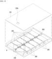
- Fig. 1 is a perspective view showing a battery pack according to an embodiment of the present disclosure.
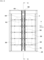
- Fig. 2 is a top view of the battery pack of Fig. 1 as viewed from above.
- Fig. 3 shows a section A of Fig. 1 , which is a view showing a state in which a hole is formed in the battery pack upper cover according to an embodiment of the present disclosure.
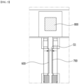
- Fig. 4 shows a section B-B of Fig. 2 , which is a cross-sectional view showing a central portion of a battery pack provided with a reflected wave absorber according to an embodiment of the present disclosure.
- the battery pack includes a plurality of first battery modules 200 and a plurality of second battery modules 300 that are arranged in two rows in a first direction, and a battery case 100 that houses the plurality of first and second battery modules 200 and 300 and includes a plurality of cross beams 110 for partitioning between the plurality of first battery modules 200 and between the plurality of second battery modules 300.
- the plurality of first battery modules 200 and the plurality of second battery modules 300 may be arranged so as to face each other.
- the thermal conductive resin layer can be formed on the bottom face of the battery case 100.
- the thermal conductive resin layer can transfer the heat generated from the plurality of first and second battery modules 200 and 300 arranged in each of the plurality of module regions to the outside of the battery pack.
- the first slave BMS 600 may be arranged in each of the plurality of first battery modules 200. More specifically, the first slave BMS 600 may be arranged in portions facing the plurality of second battery modules 300. The first slave BMS 600 may be arranged in the central portion of the battery case 100. That is, the first slave BMS 600 is arranged in one side parts of the plurality of first battery modules 200 along the first direction among the plurality of first and second battery modules 200 and 300, and thus can be arranged across the central portion of the battery case 100.
- the second slave BMS 700 may be arranged in each of the plurality of second battery modules 300. More specifically, the second slave BMS 700 may be arranged in portions facing the plurality of first battery modules 200. The second slave BMS 700 may be arranged in the central portion of the battery case 100. That is, the second slave BMS 700 is arranged in one side parts of the plurality of second battery modules 300 along the first direction between the plurality of first and second battery modules 200 and 300, and thus can be arranged across the central portion of the battery case 100.
- the slave BMS is located in the central portion of the battery case as in the present embodiment, that is, in the space between the battery modules as shown in Fig. 1 , rather than the slave BMS being located on the outer hull part of the battery case.
- the battery pack according to the present embodiment includes a first wave path guide 400 formed to extend along the first direction at the upside part of the plurality of first battery modules 200, and a second wave path guide 500 formed to extend along the first direction at the upside part of the plurality of second battery modules 300.
- the first slave BMS 600 and the second slave BMS 700 according to the present embodiment may be disposed in a space formed between the first and second wave path guides 400 and 500.
- the first wave path guide 400 is formed between the battery pack upper cover 130 and the plurality of first battery modules 200
- the second wave path guide 500 may be formed between the battery pack upper cover 130 and the plurality of second battery modules 300.
- the battery pack according to the present embodiment is mainly mounted inside the electric vehicle, and the periphery of the battery pack to be mounted is made of a metal material.
- the communication performance may deteriorate due to the multi-path phenomenon of radio waves reflected by the metal material.
- the first and second wave path guides 400 and 500 can be formed so as to cover the space between the plurality of first and second battery modules 200 and 300 provided with the plurality of first and second slave BMSs 600 and 700. Therefore, it is possible to concentrate the wireless transmission signal distribution in the space between the plurality of first and second battery modules 200 and 300 formed between the first and second wave path guides 400 and 500, thereby improving the wireless transmission performance. Further, the deterioration that may occur in communication between the master BMS 800 and the first and second slave BMSs 600 and 700 can be minimized.
- the wireless transmission coefficient S21 among the S-parameters is improved by about 18dB from -53.78dB to -35.21dB to construct a stable communication connection structure, as compared with the conventional battery pack structure in which slave BMSs are arranged outside and no wave path guide is installed,
- the first and second wave path guides 400 are formed by passing through the plurality of first and second battery modules 200 and 300 and extending in the first direction up to a position where the master BMS 800 is arranged, and the master BMS 800 is arranged at a position separated from the plurality of first and second battery modules 200 and 300 in the first direction.
- the master BMS 800 may be arranged symmetrically with the plurality of first and second battery modules 200 and 300.
- the master BMS 800 is arranged at a position symmetrically separated from the plurality of first and second slave BMSs 600 and 700, so that communication with the slave BMSs can be performed in a balanced manner. Further, the master BMS 800 is arranged in the space between the first and second wave path guides 400 and 500 together with the first and second slave BMSs 600 and 700, so that communication deterioration between the master BMS 800 and the first and second slave BMS 600 and 700 can be minimized, and wireless communication performance can be secured.
- antennas can be formed in the first and second slave BMSs 600 and 700.
- the antenna may include a chip antenna. According to the experimental example, when a chip antenna is used for the first and second slave BMS 600 and 700 according to the present embodiment, it is possible to secure excellent wireless performance by 10dB or more as compared with the case of using a pattern antenna.
- the battery pack according to the present embodiment further includes a battery pack upper cover 130 that covers the upper surface of the battery case 100. At this time, at least one hole 130a may be formed in the battery pack upper cover 130.
- the heat dissipation function of the battery pack can be performed through the hole 130a formed in the battery pack upper cover 130.
- noise may occur during communication between the BMSs due to the hole 130a that connects the outside and the inside of the battery pack.
- the size of the hole 130a increases, noise may also increase. Therefore, the number and size of the holes 130a that can appropriately satisfy both the heat dissipation performance and the noise performance at the same time can be applied.
- wireless transmission performance can be secured when designing a hole diameter of 45 mm or less.
- Noise control performance can be secured when it is designed to be less than 20mm.
- a structure in which a plurality of holes having a small diameter are arranged may be advantageous. Although only one hole 130a is shown in Fig. 1 , a plurality of holes may be arranged in the battery pack upper cover 130 according to the experimental example.
- the separation distance between the first slave BMS 600 and the second slave BMS 700 may be formed to be 50 mm.
- the distance between the two battery modules arranged in two rows was arranged as narrow as 30 mm, but the distance between the two battery modules is increased to 50 mm as in the present embodiment, so that the wireless transmission space is increased, and thus the wireless transmission performance can be improved.
- the battery pack may include a plurality of first bus bars 910 arranged so as to span between two adjacent battery modules among each battery module of the plurality of first battery modules 200, and a plurality of second bus bars 920 arranged so as to span between two adjacent battery modules among each battery module of the plurality of second battery modules 300.
- the cross beam 110 may be formed apart from the plurality of first and second bus bars 910 and 920 under the plurality of first and second bus bars 910 and 920, respectively.
- the above-mentioned battery pack can be applied to various devices.
- a device can be applied to a vehicle means such as an electric bicycle, an electric vehicle, or a hybrid vehicle, but the present disclosure is not limited thereto, and is applicable to various devices capable of using a battery module, which also falls under the scope of the present disclosure.
Landscapes
- Chemical & Material Sciences (AREA)
- Chemical Kinetics & Catalysis (AREA)
- Electrochemistry (AREA)
- General Chemical & Material Sciences (AREA)
- Engineering & Computer Science (AREA)
- Manufacturing & Machinery (AREA)
- Microelectronics & Electronic Packaging (AREA)
- Battery Mounting, Suspending (AREA)
- Details Of Aerials (AREA)
- Support Of Aerials (AREA)
Claims (12)
- Batteriepack, umfassend:eine Mehrzahl von ersten Batteriemodulen (200) und eine Mehrzahl von zweiten Batteriemodulen (300), welche in zwei Reihen in einer ersten Richtung angeordnet sind;ein Batteriegehäuse (100), welches die Mehrzahl von ersten und zweiten Batteriemodulen aufnimmt und eine Mehrzahl von Querstreben (110) zum Unterteilen zwischen der Mehrzahl von ersten Batteriemodulen und zwischen der Mehrzahl von zweiten Batteriemodulen umfasst;eine Mehrzahl von ersten Slave-BMSs (600), welche an einer Seite der Mehrzahl von ersten Batteriemodulen positioniert sind, welche zu der Mehrzahl von zweiten Batteriemodulen weisen und in der ersten Richtung angeordnet sind;eine Mehrzahl von zweiten Slave-BMSs (700), welche an einer Seite der Mehrzahl von zweiten Batteriemodulen positioniert sind, welche zu der Mehrzahl von ersten Batteriemodulen weisen und in der ersten Richtung angeordnet sind;eine Mehrzahl von ersten Absorbern (1100) für reflektierte Wellen, welche an einer Seite der Mehrzahl von ersten Batteriemodulen angeordnet sind, welche zu der Mehrzahl von zweiten Batteriemodulen weisen; undeine Mehrzahl von zweiten Absorbern (1200) für reflektierte Wellen, welche an einer Seite der Mehrzahl von zweiten Batteriemodulen angeordnet sind, welche zu der Mehrzahl von ersten Batteriemodulen weisen.
- Batteriepack nach Anspruch 1,welcher ferner einen ersten Wellenpfad-Leiter (400) umfasst, welcher dazu gebildet ist, sich entlang einer ersten Richtung an einem oberen Teil der Mehrzahl von ersten Batteriemodulen zu erstrecken; undeinen zweiten Wellenpfad-Leiter (500), welcher dazu gebildet ist, sich entlang einer ersten Richtung an einem oberen Teil der Mehrzahl von zweiten Batteriemodulen zu erstrecken.
- Batteriepack nach Anspruch 2, wobei:
die Mehrzahl von ersten Slave-BMSs und die Mehrzahl von zweiten Batteriemodulen jeweils in der ersten Richtung zwischen dem ersten Wellenpfad-Leiter und dem zweiten Wellenpfad-Leiter angeordnet sind. - Batteriepack nach Anspruch 3, wobei:die Mehrzahl von ersten Absorbern für reflektierte Wellen getrennt von dem ersten Wellenpfad-Leiter und dem ersten Slave-BMS unter dem ersten Wellenpfad-Leiter und dem ersten Slave-BMS angeordnet sind, unddie Mehrzahl von zweiten Absorbern für reflektierte Wellen getrennt von dem zweiten Wellenpfad-Leiter und dem zweiten Slave-BMS unter dem zweiten Wellenpfad-Leiter und dem zweiten Slave-BMS angeordnet sind.
- Batteriepack nach Anspruch 2, wobei:
welcher ferner ein Master-BMS (800) umfasst, welches separat von der Mehrzahl von ersten und zweiten Batteriemodulen zwischen dem ersten Wellenpfad-Leiter und dem zweiten Wellenpfad-Leiter gebildet ist. - Batteriepack nach Anspruch 5, wobei:die ersten und zweiten Wellenpfad-Leiter sich in der ersten Richtung erstreckend gebildet sind, um so durch die Mehrzahl von ersten und zweiten Batteriemodulen zu verlaufen, unddas Master-BMS an einer Position separat von der Mehrzahl von ersten und zweiten Batteriemodulen in der ersten Richtung angeordnet ist.
- Batteriepack nach Anspruch 5, wobei:die Mehrzahl von ersten Absorbern für reflektierte Wellen derart angeordnet sind, dass sie der Mehrzahl von ersten Slave-BMSs unter der Mehrzahl von ersten Slave-BMSs entsprechen, unddie Mehrzahl von zweiten Absorbern für reflektierte Wellen derart angeordnet sind, dass sie der Mehrzahl von zweiten Slave-BMSs unter der Mehrzahl von zweiten Slave-BMSs entsprechen.
- Batteriepack nach Anspruch 2, wobei:der erste Wellenpfad-Leiter zwischen der oberen Batteriepack-Abdeckung (130) und der Mehrzahl von ersten Batteriemodulen gebildet ist, undder zweite Wellenpfad-Leiter zwischen der oberen Batteriepack-Abdeckung und der Mehrzahl von zweiten Batteriemodulen gebildet ist.
- Batteriepack nach Anspruch 1, wobei:
eine Antenne in den ersten und zweiten Slave-BMSs gebildet ist. - Batteriepack nach Anspruch 1, wobei:welcher ferner eine obere Batteriepack-Abdeckung umfasst, welche die obere Fläche des Batteriegehäuses bedeckt,wobei wenigstens ein Loch (130a) in der oberen Batteriepack-Abdeckung gebildet ist.
- Batteriepack nach Anspruch 1, wobei:welcher eine Mehrzahl von ersten Sammelschienen (910) umfasst, welche derart angeordnet sind, dass sie sich zwischen zwei benachbarten Batteriemodulen unter den Batteriemodulen der Mehrzahl von ersten Batteriemodulen spannen; undeine Mehrzahl von zweiten Sammelschienen (920), welche derart angeordnet sind, dass sie sich zwischen zwei benachbarten Batteriemodulen unter den Batteriemodulen der Mehrzahl von zweiten Batteriemodulen spannen.
- Vorrichtung, umfassend den Batteriepack nach Anspruch 1.
Applications Claiming Priority (2)
| Application Number | Priority Date | Filing Date | Title |
|---|---|---|---|
| KR1020200131093A KR102837606B1 (ko) | 2020-10-12 | 2020-10-12 | 배터리 팩 및 이를 포함하는 디바이스 |
| PCT/KR2021/013818 WO2022080760A1 (ko) | 2020-10-12 | 2021-10-07 | 배터리 팩 및 이를 포함하는 디바이스 |
Publications (3)
| Publication Number | Publication Date |
|---|---|
| EP4053964A1 EP4053964A1 (de) | 2022-09-07 |
| EP4053964A4 EP4053964A4 (de) | 2024-06-19 |
| EP4053964B1 true EP4053964B1 (de) | 2025-06-25 |
Family
ID=81208453
Family Applications (1)
| Application Number | Title | Priority Date | Filing Date |
|---|---|---|---|
| EP21880407.8A Active EP4053964B1 (de) | 2020-10-12 | 2021-10-07 | Batteriepack und vorrichtung damit |
Country Status (8)
| Country | Link |
|---|---|
| US (1) | US20220376311A1 (de) |
| EP (1) | EP4053964B1 (de) |
| JP (1) | JP7387207B2 (de) |
| KR (1) | KR102837606B1 (de) |
| CN (1) | CN114902467B (de) |
| ES (1) | ES3037500T3 (de) |
| HU (1) | HUE072589T2 (de) |
| WO (1) | WO2022080760A1 (de) |
Families Citing this family (2)
| Publication number | Priority date | Publication date | Assignee | Title |
|---|---|---|---|---|
| KR102864404B1 (ko) * | 2024-01-11 | 2025-09-25 | 주식회사 엘지에너지솔루션 | 배터리 팩 |
| KR102862710B1 (ko) * | 2024-03-28 | 2025-09-23 | 주식회사 엘지에너지솔루션 | 배터리 팩 |
Family Cites Families (20)
| Publication number | Priority date | Publication date | Assignee | Title |
|---|---|---|---|---|
| US6579404B2 (en) * | 2001-01-23 | 2003-06-17 | Northrop Grumman Corporation | Method of making precision geometry advanced composite honeycomb material for spacecraft applications and honeycomb material made thereby |
| US6919516B2 (en) * | 2002-01-08 | 2005-07-19 | Mettler-Toledo | RF multiple load cell scale |
| BR112013030925B8 (pt) * | 2011-05-31 | 2023-03-21 | Lg Chemical Ltd | Sistema de armazenamento de energia tendo estrutura de conexão de ems modularizado e método para controlar o sistema |
| KR101768251B1 (ko) * | 2013-04-05 | 2017-08-30 | 삼성에스디아이 주식회사 | 배터리 모듈의 정상 연결 상태 확인을 제공하는 배터리 팩 |
| WO2015189898A1 (ja) * | 2014-06-09 | 2015-12-17 | 日立オートモティブシステムズ株式会社 | 電池システム |
| JP6256397B2 (ja) * | 2015-03-23 | 2018-01-10 | トヨタ自動車株式会社 | 電池パック |
| KR101776853B1 (ko) * | 2015-06-30 | 2017-09-12 | 인지컨트롤스 주식회사 | 배터리 팩 |
| US10050316B2 (en) * | 2016-05-13 | 2018-08-14 | Infineon Technologies Ag | Communication between battery cells |
| KR102176853B1 (ko) * | 2016-07-22 | 2020-11-10 | 주식회사 엘지화학 | 배터리 무선 제어 시스템 및 방법 |
| KR102172517B1 (ko) * | 2017-04-04 | 2020-10-30 | 주식회사 엘지화학 | 크래쉬 빔 구조를 갖는 배터리 팩 |
| KR102155331B1 (ko) * | 2017-07-06 | 2020-09-11 | 주식회사 엘지화학 | 무선 배터리 관리 시스템 및 이를 포함하는 배터리팩 |
| KR102202615B1 (ko) * | 2017-09-25 | 2021-01-12 | 주식회사 엘지화학 | 복수의 슬레이브 배터리 관리 유닛들에게 식별 정보를 할당하기 위한 장치 |
| US10777851B2 (en) * | 2018-02-15 | 2020-09-15 | Maxim Integrated Products, Inc. | Multipoint communication systems for battery management systems, and associated systems and methods |
| JP7360763B2 (ja) * | 2019-09-06 | 2023-10-13 | Apb株式会社 | 組電池 |
| JP7375581B2 (ja) | 2020-01-28 | 2023-11-08 | 株式会社デンソー | 電池パック |
| JP7215445B2 (ja) * | 2020-02-20 | 2023-01-31 | 株式会社デンソー | 電池モジュール |
| CN111224039B (zh) * | 2020-04-22 | 2020-07-24 | 江苏时代新能源科技有限公司 | 壳体、电池组及装置 |
| JP7161504B2 (ja) * | 2020-05-26 | 2022-10-26 | Apb株式会社 | 単電池ユニット |
| KR102939839B1 (ko) | 2020-06-02 | 2026-03-13 | 주식회사 엘지에너지솔루션 | 무선 통신을 위한 최적화 구조를 구비한 배터리 팩 및 이를 포함하는 자동차 |
| US20230318094A1 (en) * | 2020-08-06 | 2023-10-05 | Apb Corporation | Battery Cell |
-
2020
- 2020-10-12 KR KR1020200131093A patent/KR102837606B1/ko active Active
-
2021
- 2021-10-07 HU HUE21880407A patent/HUE072589T2/hu unknown
- 2021-10-07 JP JP2022533201A patent/JP7387207B2/ja active Active
- 2021-10-07 EP EP21880407.8A patent/EP4053964B1/de active Active
- 2021-10-07 CN CN202180007904.5A patent/CN114902467B/zh active Active
- 2021-10-07 US US17/785,275 patent/US20220376311A1/en active Pending
- 2021-10-07 WO PCT/KR2021/013818 patent/WO2022080760A1/ko not_active Ceased
- 2021-10-07 ES ES21880407T patent/ES3037500T3/es active Active
Also Published As
| Publication number | Publication date |
|---|---|
| EP4053964A1 (de) | 2022-09-07 |
| US20220376311A1 (en) | 2022-11-24 |
| ES3037500T3 (en) | 2025-10-02 |
| EP4053964A4 (de) | 2024-06-19 |
| KR102837606B1 (ko) | 2025-07-22 |
| JP7387207B2 (ja) | 2023-11-28 |
| KR20220048214A (ko) | 2022-04-19 |
| CN114902467B (zh) | 2025-07-15 |
| HUE072589T2 (hu) | 2025-11-28 |
| JP2023505470A (ja) | 2023-02-09 |
| WO2022080760A1 (ko) | 2022-04-21 |
| CN114902467A (zh) | 2022-08-12 |
Similar Documents
| Publication | Publication Date | Title |
|---|---|---|
| EP4071884A1 (de) | Batteriepack und vorrichtung damit | |
| US12166240B2 (en) | Battery module and battery pack including the same | |
| EP4224604A1 (de) | Zellenanordnung mit darauf angebrachter längserweiterungsstruktur einer beutelartigen batteriezelle und batteriepack damit | |
| EP2706589B1 (de) | Batteriemodul und batteriepack damit | |
| US12176496B2 (en) | Battery module and battery pack including the same | |
| JP7666490B2 (ja) | 電池モジュール | |
| EP4053964B1 (de) | Batteriepack und vorrichtung damit | |
| JP7744425B2 (ja) | バッテリーパック及びこれを含む自動車 | |
| EP4203150B1 (de) | Batteriemodul und batteriepack damit | |
| EP3761396A1 (de) | Batteriemodul mit schutzabdeckung zur abdeckung einer flexiblen leiterplatte | |
| US12597672B2 (en) | Battery module and battery pack including the same | |
| US20240063443A1 (en) | Battery Pack for Vehicle | |
| EP4007049A1 (de) | Batteriepack und vorrichtung damit | |
| CN115498345A (zh) | 线束隔离板、电池包和汽车 | |
| JP7159984B2 (ja) | 電池モジュール | |
| KR102874309B1 (ko) | 배터리 모듈 | |
| KR102834736B1 (ko) | 배터리 팩 | |
| CN217035891U (zh) | 电池串、电池装置及交通工具 |
Legal Events
| Date | Code | Title | Description |
|---|---|---|---|
| STAA | Information on the status of an ep patent application or granted ep patent |
Free format text: STATUS: THE INTERNATIONAL PUBLICATION HAS BEEN MADE |
|
| PUAI | Public reference made under article 153(3) epc to a published international application that has entered the european phase |
Free format text: ORIGINAL CODE: 0009012 |
|
| STAA | Information on the status of an ep patent application or granted ep patent |
Free format text: STATUS: REQUEST FOR EXAMINATION WAS MADE |
|
| 17P | Request for examination filed |
Effective date: 20220531 |
|
| AK | Designated contracting states |
Kind code of ref document: A1 Designated state(s): AL AT BE BG CH CY CZ DE DK EE ES FI FR GB GR HR HU IE IS IT LI LT LU LV MC MK MT NL NO PL PT RO RS SE SI SK SM TR |
|
| DAV | Request for validation of the european patent (deleted) | ||
| DAX | Request for extension of the european patent (deleted) | ||
| A4 | Supplementary search report drawn up and despatched |
Effective date: 20240522 |
|
| RIC1 | Information provided on ipc code assigned before grant |
Ipc: H01M 50/209 20210101ALI20240515BHEP Ipc: H01M 50/502 20210101ALI20240515BHEP Ipc: H01M 50/20 20210101ALI20240515BHEP Ipc: H01M 10/42 20060101AFI20240515BHEP |
|
| GRAP | Despatch of communication of intention to grant a patent |
Free format text: ORIGINAL CODE: EPIDOSNIGR1 |
|
| STAA | Information on the status of an ep patent application or granted ep patent |
Free format text: STATUS: GRANT OF PATENT IS INTENDED |
|
| RIC1 | Information provided on ipc code assigned before grant |
Ipc: H01M 50/209 20210101ALI20250203BHEP Ipc: H01M 50/502 20210101ALI20250203BHEP Ipc: H01M 50/20 20210101ALI20250203BHEP Ipc: H01M 10/42 20060101AFI20250203BHEP |
|
| INTG | Intention to grant announced |
Effective date: 20250219 |
|
| P01 | Opt-out of the competence of the unified patent court (upc) registered |
Free format text: CASE NUMBER: APP_13955/2025 Effective date: 20250321 |
|
| GRAS | Grant fee paid |
Free format text: ORIGINAL CODE: EPIDOSNIGR3 |
|
| GRAA | (expected) grant |
Free format text: ORIGINAL CODE: 0009210 |
|
| STAA | Information on the status of an ep patent application or granted ep patent |
Free format text: STATUS: THE PATENT HAS BEEN GRANTED |
|
| AK | Designated contracting states |
Kind code of ref document: B1 Designated state(s): AL AT BE BG CH CY CZ DE DK EE ES FI FR GB GR HR HU IE IS IT LI LT LU LV MC MK MT NL NO PL PT RO RS SE SI SK SM TR |
|
| REG | Reference to a national code |
Ref country code: GB Ref legal event code: FG4D |
|
| REG | Reference to a national code |
Ref country code: CH Ref legal event code: EP |
|
| REG | Reference to a national code |
Ref country code: CH Ref legal event code: EP |
|
| REG | Reference to a national code |
Ref country code: IE Ref legal event code: FG4D |
|
| REG | Reference to a national code |
Ref country code: DE Ref legal event code: R096 Ref document number: 602021033069 Country of ref document: DE |
|
| REG | Reference to a national code |
Ref country code: ES Ref legal event code: FG2A Ref document number: 3037500 Country of ref document: ES Kind code of ref document: T3 Effective date: 20251002 |
|
| PG25 | Lapsed in a contracting state [announced via postgrant information from national office to epo] |
Ref country code: FI Free format text: LAPSE BECAUSE OF FAILURE TO SUBMIT A TRANSLATION OF THE DESCRIPTION OR TO PAY THE FEE WITHIN THE PRESCRIBED TIME-LIMIT Effective date: 20250625 |
|
| REG | Reference to a national code |
Ref country code: LT Ref legal event code: MG9D |
|
| PG25 | Lapsed in a contracting state [announced via postgrant information from national office to epo] |
Ref country code: NO Free format text: LAPSE BECAUSE OF FAILURE TO SUBMIT A TRANSLATION OF THE DESCRIPTION OR TO PAY THE FEE WITHIN THE PRESCRIBED TIME-LIMIT Effective date: 20250925 Ref country code: GR Free format text: LAPSE BECAUSE OF FAILURE TO SUBMIT A TRANSLATION OF THE DESCRIPTION OR TO PAY THE FEE WITHIN THE PRESCRIBED TIME-LIMIT Effective date: 20250926 |
|
| PG25 | Lapsed in a contracting state [announced via postgrant information from national office to epo] |
Ref country code: BG Free format text: LAPSE BECAUSE OF FAILURE TO SUBMIT A TRANSLATION OF THE DESCRIPTION OR TO PAY THE FEE WITHIN THE PRESCRIBED TIME-LIMIT Effective date: 20250625 |
|
| PGFP | Annual fee paid to national office [announced via postgrant information from national office to epo] |
Ref country code: GB Payment date: 20250922 Year of fee payment: 5 Ref country code: BE Payment date: 20250922 Year of fee payment: 5 |
|
| PG25 | Lapsed in a contracting state [announced via postgrant information from national office to epo] |
Ref country code: HR Free format text: LAPSE BECAUSE OF FAILURE TO SUBMIT A TRANSLATION OF THE DESCRIPTION OR TO PAY THE FEE WITHIN THE PRESCRIBED TIME-LIMIT Effective date: 20250625 |
|
| PGFP | Annual fee paid to national office [announced via postgrant information from national office to epo] |
Ref country code: FR Payment date: 20250925 Year of fee payment: 5 |
|
| PG25 | Lapsed in a contracting state [announced via postgrant information from national office to epo] |
Ref country code: RS Free format text: LAPSE BECAUSE OF FAILURE TO SUBMIT A TRANSLATION OF THE DESCRIPTION OR TO PAY THE FEE WITHIN THE PRESCRIBED TIME-LIMIT Effective date: 20250925 |
|
| PG25 | Lapsed in a contracting state [announced via postgrant information from national office to epo] |
Ref country code: LV Free format text: LAPSE BECAUSE OF FAILURE TO SUBMIT A TRANSLATION OF THE DESCRIPTION OR TO PAY THE FEE WITHIN THE PRESCRIBED TIME-LIMIT Effective date: 20250625 |
|
| REG | Reference to a national code |
Ref country code: NL Ref legal event code: MP Effective date: 20250625 |
|
| PGFP | Annual fee paid to national office [announced via postgrant information from national office to epo] |
Ref country code: HU Payment date: 20251029 Year of fee payment: 5 |
|
| PG25 | Lapsed in a contracting state [announced via postgrant information from national office to epo] |
Ref country code: NL Free format text: LAPSE BECAUSE OF FAILURE TO SUBMIT A TRANSLATION OF THE DESCRIPTION OR TO PAY THE FEE WITHIN THE PRESCRIBED TIME-LIMIT Effective date: 20250625 |
|
| REG | Reference to a national code |
Ref country code: HU Ref legal event code: AG4A Ref document number: E072589 Country of ref document: HU |
|
| PG25 | Lapsed in a contracting state [announced via postgrant information from national office to epo] |
Ref country code: PT Free format text: LAPSE BECAUSE OF FAILURE TO SUBMIT A TRANSLATION OF THE DESCRIPTION OR TO PAY THE FEE WITHIN THE PRESCRIBED TIME-LIMIT Effective date: 20251027 |
|
| REG | Reference to a national code |
Ref country code: AT Ref legal event code: MK05 Ref document number: 1807538 Country of ref document: AT Kind code of ref document: T Effective date: 20250625 |
|
| PG25 | Lapsed in a contracting state [announced via postgrant information from national office to epo] |
Ref country code: IS Free format text: LAPSE BECAUSE OF FAILURE TO SUBMIT A TRANSLATION OF THE DESCRIPTION OR TO PAY THE FEE WITHIN THE PRESCRIBED TIME-LIMIT Effective date: 20251025 |
|
| PGFP | Annual fee paid to national office [announced via postgrant information from national office to epo] |
Ref country code: DE Payment date: 20250922 Year of fee payment: 5 |
|
| PG25 | Lapsed in a contracting state [announced via postgrant information from national office to epo] |
Ref country code: AT Free format text: LAPSE BECAUSE OF FAILURE TO SUBMIT A TRANSLATION OF THE DESCRIPTION OR TO PAY THE FEE WITHIN THE PRESCRIBED TIME-LIMIT Effective date: 20250625 Ref country code: SM Free format text: LAPSE BECAUSE OF FAILURE TO SUBMIT A TRANSLATION OF THE DESCRIPTION OR TO PAY THE FEE WITHIN THE PRESCRIBED TIME-LIMIT Effective date: 20250625 |
|
| PG25 | Lapsed in a contracting state [announced via postgrant information from national office to epo] |
Ref country code: CZ Free format text: LAPSE BECAUSE OF FAILURE TO SUBMIT A TRANSLATION OF THE DESCRIPTION OR TO PAY THE FEE WITHIN THE PRESCRIBED TIME-LIMIT Effective date: 20250625 |
|
| PG25 | Lapsed in a contracting state [announced via postgrant information from national office to epo] |
Ref country code: PL Free format text: LAPSE BECAUSE OF FAILURE TO SUBMIT A TRANSLATION OF THE DESCRIPTION OR TO PAY THE FEE WITHIN THE PRESCRIBED TIME-LIMIT Effective date: 20250625 |
|
| PG25 | Lapsed in a contracting state [announced via postgrant information from national office to epo] |
Ref country code: EE Free format text: LAPSE BECAUSE OF FAILURE TO SUBMIT A TRANSLATION OF THE DESCRIPTION OR TO PAY THE FEE WITHIN THE PRESCRIBED TIME-LIMIT Effective date: 20250625 |
|
| PG25 | Lapsed in a contracting state [announced via postgrant information from national office to epo] |
Ref country code: SK Free format text: LAPSE BECAUSE OF FAILURE TO SUBMIT A TRANSLATION OF THE DESCRIPTION OR TO PAY THE FEE WITHIN THE PRESCRIBED TIME-LIMIT Effective date: 20250625 |
|
| PGFP | Annual fee paid to national office [announced via postgrant information from national office to epo] |
Ref country code: ES Payment date: 20251117 Year of fee payment: 5 |
|
| PG25 | Lapsed in a contracting state [announced via postgrant information from national office to epo] |
Ref country code: RO Free format text: LAPSE BECAUSE OF FAILURE TO SUBMIT A TRANSLATION OF THE DESCRIPTION OR TO PAY THE FEE WITHIN THE PRESCRIBED TIME-LIMIT Effective date: 20250625 |
|
| PG25 | Lapsed in a contracting state [announced via postgrant information from national office to epo] |
Ref country code: DK Free format text: LAPSE BECAUSE OF FAILURE TO SUBMIT A TRANSLATION OF THE DESCRIPTION OR TO PAY THE FEE WITHIN THE PRESCRIBED TIME-LIMIT Effective date: 20250625 |
|
| PG25 | Lapsed in a contracting state [announced via postgrant information from national office to epo] |
Ref country code: IT Free format text: LAPSE BECAUSE OF FAILURE TO SUBMIT A TRANSLATION OF THE DESCRIPTION OR TO PAY THE FEE WITHIN THE PRESCRIBED TIME-LIMIT Effective date: 20250625 |
|
| PLBE | No opposition filed within time limit |
Free format text: ORIGINAL CODE: 0009261 |
|
| STAA | Information on the status of an ep patent application or granted ep patent |
Free format text: STATUS: NO OPPOSITION FILED WITHIN TIME LIMIT |