EP4007049A1 - Batteriepack und vorrichtung damit - Google Patents
Batteriepack und vorrichtung damit Download PDFInfo
- Publication number
- EP4007049A1 EP4007049A1 EP20885614.6A EP20885614A EP4007049A1 EP 4007049 A1 EP4007049 A1 EP 4007049A1 EP 20885614 A EP20885614 A EP 20885614A EP 4007049 A1 EP4007049 A1 EP 4007049A1
- Authority
- EP
- European Patent Office
- Prior art keywords
- battery
- battery pack
- frame
- module frame
- battery module
- Prior art date
- Legal status (The legal status is an assumption and is not a legal conclusion. Google has not performed a legal analysis and makes no representation as to the accuracy of the status listed.)
- Pending
Links
Images


Classifications
-
- H—ELECTRICITY
- H01—ELECTRIC ELEMENTS
- H01M—PROCESSES OR MEANS, e.g. BATTERIES, FOR THE DIRECT CONVERSION OF CHEMICAL ENERGY INTO ELECTRICAL ENERGY
- H01M50/00—Constructional details or processes of manufacture of the non-active parts of electrochemical cells other than fuel cells, e.g. hybrid cells
- H01M50/20—Mountings; Secondary casings or frames; Racks, modules or packs; Suspension devices; Shock absorbers; Transport or carrying devices; Holders
- H01M50/244—Secondary casings; Racks; Suspension devices; Carrying devices; Holders characterised by their mounting method
-
- H—ELECTRICITY
- H01—ELECTRIC ELEMENTS
- H01M—PROCESSES OR MEANS, e.g. BATTERIES, FOR THE DIRECT CONVERSION OF CHEMICAL ENERGY INTO ELECTRICAL ENERGY
- H01M10/00—Secondary cells; Manufacture thereof
- H01M10/60—Heating or cooling; Temperature control
- H01M10/62—Heating or cooling; Temperature control specially adapted for specific applications
- H01M10/625—Vehicles
-
- H—ELECTRICITY
- H01—ELECTRIC ELEMENTS
- H01M—PROCESSES OR MEANS, e.g. BATTERIES, FOR THE DIRECT CONVERSION OF CHEMICAL ENERGY INTO ELECTRICAL ENERGY
- H01M10/00—Secondary cells; Manufacture thereof
- H01M10/60—Heating or cooling; Temperature control
- H01M10/64—Heating or cooling; Temperature control characterised by the shape of the cells
- H01M10/647—Prismatic or flat cells, e.g. pouch cells
-
- H—ELECTRICITY
- H01—ELECTRIC ELEMENTS
- H01M—PROCESSES OR MEANS, e.g. BATTERIES, FOR THE DIRECT CONVERSION OF CHEMICAL ENERGY INTO ELECTRICAL ENERGY
- H01M10/00—Secondary cells; Manufacture thereof
- H01M10/60—Heating or cooling; Temperature control
- H01M10/65—Means for temperature control structurally associated with the cells
- H01M10/653—Means for temperature control structurally associated with the cells characterised by electrically insulating or thermally conductive materials
-
- H—ELECTRICITY
- H01—ELECTRIC ELEMENTS
- H01M—PROCESSES OR MEANS, e.g. BATTERIES, FOR THE DIRECT CONVERSION OF CHEMICAL ENERGY INTO ELECTRICAL ENERGY
- H01M10/00—Secondary cells; Manufacture thereof
- H01M10/60—Heating or cooling; Temperature control
- H01M10/65—Means for temperature control structurally associated with the cells
- H01M10/658—Means for temperature control structurally associated with the cells by thermal insulation or shielding
-
- H—ELECTRICITY
- H01—ELECTRIC ELEMENTS
- H01M—PROCESSES OR MEANS, e.g. BATTERIES, FOR THE DIRECT CONVERSION OF CHEMICAL ENERGY INTO ELECTRICAL ENERGY
- H01M50/00—Constructional details or processes of manufacture of the non-active parts of electrochemical cells other than fuel cells, e.g. hybrid cells
- H01M50/20—Mountings; Secondary casings or frames; Racks, modules or packs; Suspension devices; Shock absorbers; Transport or carrying devices; Holders
- H01M50/249—Mountings; Secondary casings or frames; Racks, modules or packs; Suspension devices; Shock absorbers; Transport or carrying devices; Holders specially adapted for aircraft or vehicles, e.g. cars or trains
-
- H—ELECTRICITY
- H01—ELECTRIC ELEMENTS
- H01M—PROCESSES OR MEANS, e.g. BATTERIES, FOR THE DIRECT CONVERSION OF CHEMICAL ENERGY INTO ELECTRICAL ENERGY
- H01M2220/00—Batteries for particular applications
- H01M2220/20—Batteries in motive systems, e.g. vehicle, ship, plane
-
- Y—GENERAL TAGGING OF NEW TECHNOLOGICAL DEVELOPMENTS; GENERAL TAGGING OF CROSS-SECTIONAL TECHNOLOGIES SPANNING OVER SEVERAL SECTIONS OF THE IPC; TECHNICAL SUBJECTS COVERED BY FORMER USPC CROSS-REFERENCE ART COLLECTIONS [XRACs] AND DIGESTS
- Y02—TECHNOLOGIES OR APPLICATIONS FOR MITIGATION OR ADAPTATION AGAINST CLIMATE CHANGE
- Y02E—REDUCTION OF GREENHOUSE GAS [GHG] EMISSIONS, RELATED TO ENERGY GENERATION, TRANSMISSION OR DISTRIBUTION
- Y02E60/00—Enabling technologies; Technologies with a potential or indirect contribution to GHG emissions mitigation
- Y02E60/10—Energy storage using batteries
Definitions
- the present invention relates to a battery pack and a device including the same. More particularly, the present invention relates to a battery pack including a pack frame with a simplified shape and a device including the same.
- Rechargeable batteries are receiving a lot of attention as an energy source in various product groups such as mobile devices and electric vehicles. These rechargeable batteries are a powerful energy resource that may replace the use of existing products that use fossil fuels, and are spotlighted as an environmentally-friendly energy source because they do not generate byproducts from energy use.
- the battery module constituting the battery pack includes a battery cell laminated body in which a plurality of battery cells are laminated and a battery module frame accommodating the battery cell laminated body, and is coupled to the battery pack frame.
- the conventional battery pack frame is provided with four protruded shapes per module for the coupling at the part on which the battery module frame is mounted, so that the battery module frame is coupled thereto.
- the left and right positions and heights of the protruded shapes had to be aligned, so there is a problem that an assembly tolerance increases.
- the weight of the entire battery pack frame increases and the shape becomes complicated.
- the problem to be solved by the present invention is to provide a battery pack that may be assembled more easily by simplifying the shape of the battery pack frame to reduce the weight of the battery pack and to reduce an assemble tolerance.
- a battery pack includes: a battery module frame accommodating a battery cell laminated body; and a battery pack frame to which the battery module frame is mounted, wherein the battery module frame includes a protruded part having a shape protruded from the lower part of the battery module frame toward the battery pack frame and combined with the battery pack frame, and one side of the battery pack frame facing the battery module frame is formed flat.
- the battery pack frame may include a coupling hole in a position corresponding to the protruded part.
- the protruded part and the coupling hole may be coupled to each other via a mounting member.
- the battery module frame may include an end plate that covers the front and rear surfaces of the battery cell laminated body, and the protruded part may be protruded from the bottom of the end plate.
- a through-hole formed through the protruded part at both ends of the end plate may be included, and the mounting member may be inserted through the through-hole and the coupling hole to be jointed.
- a thermal conductive resin layer positioned between the battery module frame and the battery pack frame may be further included.
- the thickness of the thermal conductive resin layer may be the same as the thickness of the protruded part protruded from the bottom of the battery module frame.
- the battery module frame may further include an insulating member attached to the end of the protruded part.
- a battery module includes a battery cell laminated body, and a battery module frame accommodating the battery cell laminated body, wherein the battery module frame includes a module frame covering fours surfaces of the battery cell laminated body and including an opening exposing the end of both sides in the length direction of the battery cell laminated body, and an end plate coupled to the opening of both sides of the module frame, wherein the end plate includes a protruded part protruded under the end plate.
- the end plate may include a through-hole formed through the protruded part on both sides.
- a device may include at least one battery pack described above.
- the battery pack according to an embodiment of the present invention may reduce the weight of the battery pack by simplifying the shape of the battery pack frame, and may be assembled more easily by reducing an assemble tolerance, and may prevent a waste of the thermally conductive resin provided in the battery pack.
- first and second used in this application may be used to describe various configurations elements, but the constituent elements should not be limited by the terms. The above terms are used only for distinguishing one constituent element from other constituent elements.
- FIG. 1 is a view showing a battery module according to an embodiment of the present invention
- FIG. 2 is an enlarged view of a part A of FIG. 1
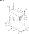
- FIG. 3 is a view showing an appearance before a battery pack according to an embodiment of the present invention that is assembled
- FIG. 4 is a view showing an appearance after a battery pack according to an embodiment of the present invention that is assembled
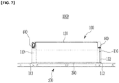
- FIG. 5 is a side view of a battery pack according to an embodiment of the present invention
- FIG. 6 is a schematic view to explain an effect of a battery pack according to an embodiment of the present invention.
- a battery module 10 includes a battery module frame 100 accommodating a battery cell laminated body, and at this time, the battery module frame 100 includes a module frame 120 that covers four surfaces of the battery cell laminated body and includes openings exposing both ends in the length direction of the battery cell laminated body, and an end plate 110 coupled to the openings on both sides of the module frame 120, and the end plate 110 includes a protruded part 112 protruded downward.
- the battery cell is a rechargeable battery and may be configured as a pouch-type rechargeable battery.
- a battery cell may be composed of a plurality thereof, and a plurality of battery cells may be stacked to each other so as to be electrically connected to each other to form a battery cell laminated body.
- Each of these plurality of battery cells may include an electrode assembly, a battery case, and an electrode lead protruded from the electrode assembly.
- the battery module frame 100 accommodates a battery cell laminated body formed by stacking a plurality of battery cells, and physically protects the battery cell laminated body.
- the battery module frame 100 may include an end plate 110 formed to cover the front and rear surfaces of the battery cell laminated body and a module frame 120 formed to cover upper, lower, left, and right surfaces of the battery cell laminated body.
- the module frame 120 may be in the form of a square tube in which the upper, lower, left, and right surfaces are integrally formed, or may be formed of a U-shaped frame that integrally covers any one of the upper and lower surfaces and the left and right surfaces, and a plate coupled to the open surface of the U-shaped frame.
- the end plate 110 may be joined to the module frame 120 through welding, and a bus bar frame formed between the end plate 110 and the battery cell laminated body and the battery cell laminated body may be physically protected.
- the end plate 110 includes a protruded part 112 protruded downwards at the bottom.
- This protruded part 112 is a configuration for coupling with the battery pack frame to be described later, and the detailed configuration is described later.
- the battery pack 1000 includes a battery module frame 100 for accommodating a battery cell laminated body, and a battery pack frame 200 on which the battery module frame 100 is mounted, the battery module frame 100 includes a protruded part 112 that has a protruded shape toward the battery pack frame 200 and combines with the battery pack frame 200, and one side of the battery pack frame 200 facing the battery module frame 100 is formed flat.
- the battery pack frame 200 is formed to accommodate the battery module frame 100.
- the battery pack frame 200 may physically protect a plurality of battery cells accommodated in the battery module frame 100, is mounted on various devices that require power, and may supply the power generated from the battery modules formed inside the battery pack frame 300 to the devices.
- a thermal conductive resin layer 300 may be positioned between the battery pack frame 200 and the battery module frame 100.
- the thermal conductive resin layer 300 may be made of a thermal conductive resin for heat dissipation, and the heat generated from the battery module 10 may be radiated to the battery pack frame 200 side.
- the battery module frame 100 may be mounted on the upper side of the battery pack frame 200. More specifically, the upper surface of the battery pack frame 200 includes a coupling hole 210 for coupling with the battery module frame 100, and may be coupled to the battery pack frame 200 in such a way that the protruded part 112 of the battery module frame 100 is mounted in the coupling hole 210.
- the mounting member 400 may couple the battery pack frame 200 and the battery module frame 100 together. More specifically, through-holes 111 formed through the protruded part 112 are formed at both ends of the end plate 110 formed at the front and rear of the battery module frame 100, a coupling hole 210 for coupling thereto is formed at the top of the battery pack frame 200, and the mounting member 400 integrally penetrates the through-holes 111 formed at both ends of the end plate 110 and the coupling holes 210 formed at the top of the battery pack frame 200, thereby combining the end plate 110 and the battery pack frame 200.
- the mounting member 400 may be inserted through the coupling hole 210 to the inside of the battery pack frame 200.
- the mounting member 400 may be formed as a bolt.
- the mounting member is not limited to the bolt, and it is possible to combine the battery module frame and the battery pack frame by utilizing various embodiments.
- the upper surface of the battery pack frame 200 is formed flat without a protruding shape, and only the coupling hole 210 is formed.
- the combination of the battery pack frame 200 and the battery module frame 100 may be achieved by aligning the protruded part 112 protruded to the lower part of the battery module frame 100, that is, the lower part of the end plate 110 in the left and right directions only so as to coaxially position the through-hole 111 of the protruded part 112 and the coupling hole 210 of the battery pack frame 200 and then inserting the mounting member 400.
- FIG. 6 it is possible to combine them by only aligning the left and right directions, thereby reducing the assembly tolerance.
- FIG. 6 (a) is a view showing an alignment with the battery pack frame 200 in which a conventional protrude shape is formed, and in this case, the alignment in the vertical direction is required as well as the alignment in the left and right directions, thereby increasing the assembly tolerance.
- the distance between the battery pack frame 200 and the battery module frame 100 increases because the vertical direction is not properly aligned, since the injection of the thermal conductive resin for the formation of the thermal conductive resin layer 300 positioned therebetween is performed in excess of the quantity, there is a problem in that materials such as the thermal conductive resin is wasted.
- the present invention it is possible to align the through-hole 111 of the protruded part 112 and the coupling hole 210 of the battery pack frame 200 only by the left-right alignment, so this problem may be prevented. That is, by designing the protruded part 112 to have the same thickness as the thickness of the thermal conductive resin layer 300, there is a gap of as much as the design amount between the battery pack frame 200 and the battery module frame 100 just by aligning the through-hole 111 of the protruded part 112 with the coupling hole 210 of the battery pack frame 200, so that a quantity of the thermal conductive resin may be coated to the corresponding space. Therefore, it is possible to prevent unnecessary waste of the thermal conductive resin for the formation of the thermal conductive resin layer 300.
- the weight may be reduced by simplifying the structure of the battery pack frame 200, and when assembling the battery module frame 100 and the battery pack frame 200, the assembly tolerance is reduced, thereby not only simplifying the assembly process and but also preventing the unnecessary waste of materials such as the thermal conductive resin.
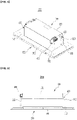
- FIG. 7 is a side view of a battery pack according to another embodiment of the present invention.
- another embodiment of the present invention has the same structure as the previous embodiment except for further forming an insulating member 113 on a lower surface of a protruded part 112 of the battery module frame 100 in contact with the battery pack frame 200.
- the insulating member 113 is formed on the lower surface of the protruded part 112 of the battery module frame 100, and may be positioned between the battery module frame 100 and the battery pack frame 200. Through this, heat transfer to the battery pack frame 200 and the battery module frame 100 connected thereto may be blocked.
- both the battery pack frame 200 and the battery module frame 100 are made of metal, conventionally, heat transfer occurs between the battery module frame 100 and the battery pack frame 200, and heat transfer occurs between the battery pack frame 200 and the battery module frame 100, which are influenced by the outside and have a temperature gradient, thereby a plurality of battery cells accommodated in the battery module frame 200 could be directly affected by the temperature of the battery pack frame 200 .
- the insulating member 113 is formed between the battery module frame 100 and the battery pack frame 200, it can prevent the heat transfer due to the metal contact in advance and minimize the effect of an external temperature on the battery cell.
- the battery pack may have a structure in which a battery management system (BMS) that manages a temperature or voltage of the battery and a cooling device are added and packed.
- BMS battery management system
- the aforementioned battery pack may be applied to various devices.
- the device may be applied to a vehicle such as an electric bicycle, an electric vehicle, or a hybrid vehicle, but the present invention is not limited thereto, and may be applied to various devices that can use a battery module, and this is also included in the scope of the present invention.
Landscapes
- Chemical & Material Sciences (AREA)
- Chemical Kinetics & Catalysis (AREA)
- Electrochemistry (AREA)
- General Chemical & Material Sciences (AREA)
- Engineering & Computer Science (AREA)
- Manufacturing & Machinery (AREA)
- Aviation & Aerospace Engineering (AREA)
- Battery Mounting, Suspending (AREA)
- Secondary Cells (AREA)
Applications Claiming Priority (2)
| Application Number | Priority Date | Filing Date | Title |
|---|---|---|---|
| KR1020190142734A KR20210056079A (ko) | 2019-11-08 | 2019-11-08 | 전지팩 및 이를 포함하는 디바이스 |
| PCT/KR2020/095129 WO2021091364A1 (ko) | 2019-11-08 | 2020-10-29 | 전지팩 및 이를 포함하는 디바이스 |
Publications (2)
| Publication Number | Publication Date |
|---|---|
| EP4007049A1 true EP4007049A1 (de) | 2022-06-01 |
| EP4007049A4 EP4007049A4 (de) | 2022-11-16 |
Family
ID=75848853
Family Applications (1)
| Application Number | Title | Priority Date | Filing Date |
|---|---|---|---|
| EP20885614.6A Pending EP4007049A4 (de) | 2019-11-08 | 2020-10-29 | Batteriepack und vorrichtung damit |
Country Status (6)
| Country | Link |
|---|---|
| US (1) | US20220344761A1 (de) |
| EP (1) | EP4007049A4 (de) |
| JP (1) | JP7438331B2 (de) |
| KR (1) | KR20210056079A (de) |
| CN (1) | CN114402480A (de) |
| WO (1) | WO2021091364A1 (de) |
Family Cites Families (16)
| Publication number | Priority date | Publication date | Assignee | Title |
|---|---|---|---|---|
| JP5326221B2 (ja) | 2007-04-26 | 2013-10-30 | トヨタ自動車株式会社 | 電源装置 |
| KR101503983B1 (ko) * | 2012-12-27 | 2015-03-18 | 에이치엘그린파워 주식회사 | 배터리모듈조립체의 하우징 구조 및 하우징 방법 |
| KR20150069732A (ko) * | 2013-12-16 | 2015-06-24 | 삼성에스디아이 주식회사 | 배터리 모듈 |
| JP6354471B2 (ja) * | 2014-09-04 | 2018-07-11 | 株式会社Gsユアサ | 蓄電装置 |
| KR102032504B1 (ko) * | 2015-11-06 | 2019-11-08 | 주식회사 엘지화학 | 내충격성이 향상된 배터리 모듈 |
| JP6601254B2 (ja) | 2016-02-19 | 2019-11-06 | 株式会社豊田自動織機 | 電池モジュールの組付け方法及び電池モジュール |
| KR102101906B1 (ko) * | 2016-10-21 | 2020-04-17 | 주식회사 엘지화학 | 조립 가이드 기능의 체결 부재를 포함하는 전지팩 |
| KR102086127B1 (ko) | 2016-10-31 | 2020-03-06 | 주식회사 엘지화학 | 배터리의 엣지 면에 직접 냉각 방식이 적용된 배터리 팩 |
| WO2018128294A1 (ko) * | 2017-01-06 | 2018-07-12 | 삼성에스디아이 주식회사 | 전지 모듈 및 이를 포함하는 자동차 |
| US11251490B2 (en) | 2017-08-21 | 2022-02-15 | Sanyo Electric Co., Ltd. | Battery module and vehicle equipped with same |
| CN207398230U (zh) * | 2017-10-26 | 2018-05-22 | 宁德时代新能源科技股份有限公司 | 电池包 |
| KR102301195B1 (ko) * | 2017-12-01 | 2021-09-09 | 주식회사 엘지에너지솔루션 | 배터리 팩 |
| JP6955112B2 (ja) | 2018-09-26 | 2021-10-27 | ビークルエナジージャパン株式会社 | 電池パック |
| CN208923207U (zh) | 2018-11-01 | 2019-05-31 | 宁德时代新能源科技股份有限公司 | 一种电池模组端板及其电池模组 |
| CN209447945U (zh) * | 2018-12-30 | 2019-09-27 | 宁德时代新能源科技股份有限公司 | 一种电池包 |
| KR102640879B1 (ko) * | 2019-02-08 | 2024-02-23 | 에스케이온 주식회사 | 배터리 모듈 및 이의 제조방법 |
-
2019
- 2019-11-08 KR KR1020190142734A patent/KR20210056079A/ko not_active Application Discontinuation
-
2020
- 2020-10-29 JP JP2022512416A patent/JP7438331B2/ja active Active
- 2020-10-29 EP EP20885614.6A patent/EP4007049A4/de active Pending
- 2020-10-29 US US17/642,504 patent/US20220344761A1/en active Pending
- 2020-10-29 CN CN202080064517.0A patent/CN114402480A/zh active Pending
- 2020-10-29 WO PCT/KR2020/095129 patent/WO2021091364A1/ko unknown
Also Published As
| Publication number | Publication date |
|---|---|
| EP4007049A4 (de) | 2022-11-16 |
| WO2021091364A1 (ko) | 2021-05-14 |
| US20220344761A1 (en) | 2022-10-27 |
| JP7438331B2 (ja) | 2024-02-26 |
| CN114402480A (zh) | 2022-04-26 |
| KR20210056079A (ko) | 2021-05-18 |
| JP2022545032A (ja) | 2022-10-24 |
Similar Documents
| Publication | Publication Date | Title |
|---|---|---|
| EP3876303A1 (de) | Batteriemodul und batteriepack damit | |
| JP2022523987A (ja) | バッテリーモジュール及びバッテリーパック | |
| EP3934010A1 (de) | Batteriemodul und batteriepack damit | |
| US20220376340A1 (en) | Battery Module and Battery Pack Including the Same | |
| JP7262880B2 (ja) | 電池モジュールおよびこれを含む電池パック | |
| KR20220102950A (ko) | 전지 모듈 및 이를 포함하는 전지 팩 | |
| EP4027443A1 (de) | Batteriemodul und batteriesatz damit | |
| EP4007049A1 (de) | Batteriepack und vorrichtung damit | |
| EP4020688A1 (de) | Batteriemodul und batteriepack damit | |
| JP7262882B2 (ja) | 電池モジュールおよびこれを含む電池パック | |
| EP4020685A1 (de) | Batteriemodul und herstellungsverfahren dafür | |
| US20220190404A1 (en) | Battery pack and device including the same | |
| KR20210092563A (ko) | 전지 모듈 및 이를 포함하는 전지팩 | |
| KR20220012045A (ko) | 전지 모듈 및 이를 포함하는 전지팩 | |
| KR20210071552A (ko) | 전지 모듈 및 이를 포함하는 전지 팩 | |
| EP4152496A1 (de) | Batteriemodul und batteriepack damit | |
| US20220407138A1 (en) | Battery Module and Manufacturing Method Thereof | |
| US20220352589A1 (en) | Battery module and battery pack including the same | |
| KR20210113754A (ko) | 전지팩 및 이를 포함하는 디바이스 | |
| KR20210069426A (ko) | 전지 모듈 및 이를 포함하는 전지팩 | |
| KR20210092564A (ko) | 전지 모듈 및 그 제조 방법 | |
| KR20230097897A (ko) | 로지컬 셀, 이차전지 모듈 및 이를 포함하는 이차전지 팩 | |
| KR20220060715A (ko) | 전지 모듈 및 이를 포함하는 전지팩 | |
| KR20220069502A (ko) | 전지 모듈 및 이를 포함하는 전지팩 | |
| KR20210070774A (ko) | 전지 모듈 및 이를 포함하는 전지 팩 |
Legal Events
| Date | Code | Title | Description |
|---|---|---|---|
| STAA | Information on the status of an ep patent application or granted ep patent |
Free format text: STATUS: THE INTERNATIONAL PUBLICATION HAS BEEN MADE |
|
| PUAI | Public reference made under article 153(3) epc to a published international application that has entered the european phase |
Free format text: ORIGINAL CODE: 0009012 |
|
| STAA | Information on the status of an ep patent application or granted ep patent |
Free format text: STATUS: REQUEST FOR EXAMINATION WAS MADE |
|
| 17P | Request for examination filed |
Effective date: 20220224 |
|
| AK | Designated contracting states |
Kind code of ref document: A1 Designated state(s): AL AT BE BG CH CY CZ DE DK EE ES FI FR GB GR HR HU IE IS IT LI LT LU LV MC MK MT NL NO PL PT RO RS SE SI SK SM TR |
|
| A4 | Supplementary search report drawn up and despatched |
Effective date: 20221014 |
|
| RIC1 | Information provided on ipc code assigned before grant |
Ipc: H01M 10/625 20140101ALI20221011BHEP Ipc: H01M 10/653 20140101ALI20221011BHEP Ipc: H01M 50/20 20210101AFI20221011BHEP |
|
| DAV | Request for validation of the european patent (deleted) | ||
| DAX | Request for extension of the european patent (deleted) |