EP4053635B1 - Bildvorbereitung für bandbelichtungsmaschine und bandbelichtungsmaschine - Google Patents
Bildvorbereitung für bandbelichtungsmaschine und bandbelichtungsmaschine Download PDFInfo
- Publication number
- EP4053635B1 EP4053635B1 EP22159798.2A EP22159798A EP4053635B1 EP 4053635 B1 EP4053635 B1 EP 4053635B1 EP 22159798 A EP22159798 A EP 22159798A EP 4053635 B1 EP4053635 B1 EP 4053635B1
- Authority
- EP
- European Patent Office
- Prior art keywords
- image
- strip
- web
- images
- exposure
- Prior art date
- Legal status (The legal status is an assumption and is not a legal conclusion. Google has not performed a legal analysis and makes no representation as to the accuracy of the status listed.)
- Active
Links
Images




Classifications
-
- G—PHYSICS
- G03—PHOTOGRAPHY; CINEMATOGRAPHY; ANALOGOUS TECHNIQUES USING WAVES OTHER THAN OPTICAL WAVES; ELECTROGRAPHY; HOLOGRAPHY
- G03F—PHOTOMECHANICAL PRODUCTION OF TEXTURED OR PATTERNED SURFACES, e.g. FOR PRINTING, FOR PROCESSING OF SEMICONDUCTOR DEVICES; MATERIALS THEREFOR; ORIGINALS THEREFOR; APPARATUS SPECIALLY ADAPTED THEREFOR
- G03F7/00—Photomechanical, e.g. photolithographic, production of textured or patterned surfaces, e.g. printing surfaces; Materials therefor, e.g. comprising photoresists; Apparatus specially adapted therefor
- G03F7/70—Microphotolithographic exposure; Apparatus therefor
- G03F7/70691—Handling of masks or workpieces
- G03F7/70791—Large workpieces, e.g. glass substrates for flat panel displays or solar panels
-
- G—PHYSICS
- G03—PHOTOGRAPHY; CINEMATOGRAPHY; ANALOGOUS TECHNIQUES USING WAVES OTHER THAN OPTICAL WAVES; ELECTROGRAPHY; HOLOGRAPHY
- G03F—PHOTOMECHANICAL PRODUCTION OF TEXTURED OR PATTERNED SURFACES, e.g. FOR PRINTING, FOR PROCESSING OF SEMICONDUCTOR DEVICES; MATERIALS THEREFOR; ORIGINALS THEREFOR; APPARATUS SPECIALLY ADAPTED THEREFOR
- G03F7/00—Photomechanical, e.g. photolithographic, production of textured or patterned surfaces, e.g. printing surfaces; Materials therefor, e.g. comprising photoresists; Apparatus specially adapted therefor
- G03F7/70—Microphotolithographic exposure; Apparatus therefor
- G03F7/70216—Mask projection systems
- G03F7/70275—Multiple projection paths, e.g. array of projection systems, microlens projection systems or tandem projection systems
-
- G—PHYSICS
- G03—PHOTOGRAPHY; CINEMATOGRAPHY; ANALOGOUS TECHNIQUES USING WAVES OTHER THAN OPTICAL WAVES; ELECTROGRAPHY; HOLOGRAPHY
- G03F—PHOTOMECHANICAL PRODUCTION OF TEXTURED OR PATTERNED SURFACES, e.g. FOR PRINTING, FOR PROCESSING OF SEMICONDUCTOR DEVICES; MATERIALS THEREFOR; ORIGINALS THEREFOR; APPARATUS SPECIALLY ADAPTED THEREFOR
- G03F7/00—Photomechanical, e.g. photolithographic, production of textured or patterned surfaces, e.g. printing surfaces; Materials therefor, e.g. comprising photoresists; Apparatus specially adapted therefor
- G03F7/70—Microphotolithographic exposure; Apparatus therefor
- G03F7/70383—Direct write, i.e. pattern is written directly without the use of a mask by one or multiple beams
-
- G—PHYSICS
- G03—PHOTOGRAPHY; CINEMATOGRAPHY; ANALOGOUS TECHNIQUES USING WAVES OTHER THAN OPTICAL WAVES; ELECTROGRAPHY; HOLOGRAPHY
- G03F—PHOTOMECHANICAL PRODUCTION OF TEXTURED OR PATTERNED SURFACES, e.g. FOR PRINTING, FOR PROCESSING OF SEMICONDUCTOR DEVICES; MATERIALS THEREFOR; ORIGINALS THEREFOR; APPARATUS SPECIALLY ADAPTED THEREFOR
- G03F7/00—Photomechanical, e.g. photolithographic, production of textured or patterned surfaces, e.g. printing surfaces; Materials therefor, e.g. comprising photoresists; Apparatus specially adapted therefor
- G03F7/70—Microphotolithographic exposure; Apparatus therefor
- G03F7/70425—Imaging strategies, e.g. for increasing throughput or resolution, printing product fields larger than the image field or compensating lithography- or non-lithography errors, e.g. proximity correction, mix-and-match, stitching or double patterning
- G03F7/70466—Multiple exposures, e.g. combination of fine and coarse exposures, double patterning or multiple exposures for printing a single feature
-
- G—PHYSICS
- G03—PHOTOGRAPHY; CINEMATOGRAPHY; ANALOGOUS TECHNIQUES USING WAVES OTHER THAN OPTICAL WAVES; ELECTROGRAPHY; HOLOGRAPHY
- G03F—PHOTOMECHANICAL PRODUCTION OF TEXTURED OR PATTERNED SURFACES, e.g. FOR PRINTING, FOR PROCESSING OF SEMICONDUCTOR DEVICES; MATERIALS THEREFOR; ORIGINALS THEREFOR; APPARATUS SPECIALLY ADAPTED THEREFOR
- G03F7/00—Photomechanical, e.g. photolithographic, production of textured or patterned surfaces, e.g. printing surfaces; Materials therefor, e.g. comprising photoresists; Apparatus specially adapted therefor
- G03F7/70—Microphotolithographic exposure; Apparatus therefor
- G03F7/70425—Imaging strategies, e.g. for increasing throughput or resolution, printing product fields larger than the image field or compensating lithography- or non-lithography errors, e.g. proximity correction, mix-and-match, stitching or double patterning
- G03F7/70475—Stitching, i.e. connecting image fields to produce a device field, the field occupied by a device such as a memory chip, processor chip, CCD, flat panel display
-
- G—PHYSICS
- G03—PHOTOGRAPHY; CINEMATOGRAPHY; ANALOGOUS TECHNIQUES USING WAVES OTHER THAN OPTICAL WAVES; ELECTROGRAPHY; HOLOGRAPHY
- G03F—PHOTOMECHANICAL PRODUCTION OF TEXTURED OR PATTERNED SURFACES, e.g. FOR PRINTING, FOR PROCESSING OF SEMICONDUCTOR DEVICES; MATERIALS THEREFOR; ORIGINALS THEREFOR; APPARATUS SPECIALLY ADAPTED THEREFOR
- G03F9/00—Registration or positioning of originals, masks, frames, photographic sheets or textured or patterned surfaces, e.g. automatically
- G03F9/70—Registration or positioning of originals, masks, frames, photographic sheets or textured or patterned surfaces, e.g. automatically for microlithography
- G03F9/7003—Alignment type or strategy, e.g. leveling, global alignment
-
- G—PHYSICS
- G03—PHOTOGRAPHY; CINEMATOGRAPHY; ANALOGOUS TECHNIQUES USING WAVES OTHER THAN OPTICAL WAVES; ELECTROGRAPHY; HOLOGRAPHY
- G03F—PHOTOMECHANICAL PRODUCTION OF TEXTURED OR PATTERNED SURFACES, e.g. FOR PRINTING, FOR PROCESSING OF SEMICONDUCTOR DEVICES; MATERIALS THEREFOR; ORIGINALS THEREFOR; APPARATUS SPECIALLY ADAPTED THEREFOR
- G03F9/00—Registration or positioning of originals, masks, frames, photographic sheets or textured or patterned surfaces, e.g. automatically
- G03F9/70—Registration or positioning of originals, masks, frames, photographic sheets or textured or patterned surfaces, e.g. automatically for microlithography
- G03F9/7003—Alignment type or strategy, e.g. leveling, global alignment
- G03F9/7007—Alignment other than original with workpiece
Definitions
- the risk of a slight gap, even of very small size, appearing between image n and image n+1 is greatly reduced, due for example to a positioning error of the strip and/or the insolation device.
- the inventors determined that the fact that the overlap zone is exposed twice, once during the projection of image n and a second time during the projection of image n+1, does not cause any defect, or in any case no major defect, in the final product.
- the sequence of images comprises all identical images. This is particularly the case when it is desired to reproduce the same pattern regularly on the strip.
- the method comprises a step of cutting a primary digital image into a plurality of secondary digital images of shorter length, this plurality of secondary digital images forming said succession of images. This makes it possible to project, piece by piece, and thus to reconstitute on the strip, the entire primary image taking into account the maximum size of the exposure zone.
- an image segment from the upstream edge of image n is added to image n+1, beyond its original downstream edge, or an image segment from the downstream edge of image n+1 is added to image n, beyond its original upstream edge.
- This added image segment can thus constitute all or part of the overlap zone, without altering the specific content of image n+1, of image n respectively.
- the overlap zone receives substantially twice the same image segment, which avoids a possible incoherent superposition of two different image segments.
- the overlap zone has a length at least equal to 5 ⁇ m, preferably at least equal to 10 ⁇ m, at any point of the interface between image n+1 and image n. This ensures continuity at any point of the interface.
- the first image is positioned, with possible distortion, so as to cause four predetermined registration points of the image to coincide with four test patterns of the strip.
- the sights are actual marks provided on the strip. These may include holes made in the strip. However, the strip edges may also be detected by one or more vision devices.
- test patterns are added to the image n near its two upstream angles.
- a test pattern is considered to be near an element of the image if the distance separating it from this element of the image is less than 10%, and preferably less than 5%, of the length of the image.
- At least two patterns are added to image n at a distance from the upstream edge of image n.
- a pattern is considered to be at a distance from an element of the image if the distance separating it from this element of the image is greater than 10% of the length of the image.
- These patterns are useful when a double-sided exposure is planned for the strip in question in order to facilitate the alignment of the back image with respect to the already exposed front image.
- at least one of these patterns is provided in the downstream half of image n.
- these two patterns are provided near a lateral edge of image n.
- the n+1 image is positioned without distortion based on at least two patterns of the strip.
- the n+1 image is positioned, with possible deformation, so as to make four predetermined calibration points of the image coincide with four test patterns of the strip.
- the n+1 image is positioned based on four real marks on the tape, these marks being able for example to be holes.
- Such positioning is particularly easy to implement and allows automatic tape tracking. However, it can lead to significant distortions of the image and, possibly, to defects in consistency of the overlap area if the projection device is poorly centered.
- such a method ensures very good alignment of the front and back images and is therefore particularly suitable for double-sided applications.
- image n+1 is positioned based on two real targets exposed with image n and two real marks on the strip, these marks being able to be holes for example. Such positioning is also easy to implement and further ensures good consistency of the overlap area. Strip tracking is also ensured.
- image n+1 is positioned based on two real targets exposed with image n and two virtual targets resulting from the detection of the strip edges. Such a solution aims to imitate the above positioning solution in the absence of a real mark on the strip.
- image n+1 is positioned based on two real targets exposed with image n and two virtual targets resulting from the detection of real marks on the strip, these marks being able for example to be holes.
- This solution aims to correct the position of the real marks when the latter deviate too significantly from their theoretical positions.
- the two virtual targets thus considered can share the same barycenter as the corresponding real marks with the constraint, on the one hand, of being aligned in the direction transverse to the running direction and, on the other hand, of being spaced by a predetermined distance. In this way, it is ensured that the upstream and downstream edges of all the images, with the possible exception of the first two, are all parallel, which ensures good consistency of the overlap zone.
- the strip tracking can be done by limiting the deformation undergone by image n+1 to a unidirectional shear deformation.
- such a method can cause a shift between the positioning of the front image and that of the back image such that this embodiment is preferably reserved for single-sided applications.
- the positioning method used varies depending on the image. This variation may be predetermined, according to a particular alternation for example, or determined during operation as a function of certain parameters of the exposure, linked for example to the image or the strip.
- the local deformation of the strip can be measured before the projection of each image and the method of positioning the image considered can be selected as a function of this measurement.
- the present disclosure also relates to a machine for exposing a moving web, comprising a support, comprising an exposure zone, an exposure arrangement, provided opposite the exposure zone of the support, comprising at least one light source and at least one projection device configured to project a succession of images in the exposure zone from one or more digital files, a web guiding and driving device, configured to stretch a web on the support and to move it in a running direction passing through the exposure zone, and a digital image preparation unit, configured to position, orient, modify and/or deform an image before its projection by the projection device, in which the digital image preparation unit is configured to implement an image preparation method according to any one of the preceding embodiments.
- At least one light source of the insolation device is an ultraviolet source.
- the projection device comprises at least one matrix of controllable micro-mirrors.
- the projection device could however implement another direct projection technique, and in particular a UV laser or UV LED source associated with galvanometric mirrors, or with a rotating polygonal mirror, and with a high-speed modulation device such as an acousto-optic modulator for example.
- the projection device comprises at least one, and preferably several, exposure heads capable of moving to scan, possibly collectively, the entire exposure area.
- the projection device is capable of projecting an image onto the entire exposure area at once.
- the guiding and driving device is provided with a centering device configured to center the strip in the exposure zone in the direction transverse to the running direction. This makes it possible to compensate for any large-scale deformations of the strip.
- the exposure machine comprises an unwinder, upstream of the support, configured to receive a roll of strip to be exposed and to unwind said strip and transmit it to the guide and drive device.
- the exposure machine comprises a winder, downstream of the support, configured to receive the exposed strip after it has passed through the exposure zone and to wind it in the form of a roll of exposed strip.
- the exposure machine comprises a first vision device, comprising at least one camera, and preferably two or four cameras, provided facing the support, configured to identify and locate a strip edge and/or targets on the front side of the strip. These targets may in particular be exposed targets or holes.
- the exposure machine comprises a second vision device, comprising at least one camera, and preferably three or five cameras, provided in the support, configured to identify and locate marks on the back side of the strip. These marks may in particular be exposed marks or holes.
- the strip has a width of between 150 and 630 mm.
- the exposure machine can receive strips of varying sizes, the exposure machine being configured to adjust the centering of its components, and in particular of its projection device and its vision devices, depending on the width of the strip and the size of the images.
- each image comprises a width of between 150 and 630 mm and a length of between 15 and 685 mm.
- the present disclosure also relates to a computer program comprising instructions for carrying out the steps of the image preparation method of any of the preceding embodiments.
- a computer program may in practice comprise a plurality of subroutines cooperating with each other.
- FIG. 1 represents an exposure machine 1 according to the disclosure. It comprises an exposure table 2, a strip unwinder 3, a strip guiding and driving device 4, a strip winder 5, an exposure device 6 and a cooling device. Some of these components are also visible on the Figure 2 .
- the exposure table 2 acting as a support, has a flat upper surface defining an exposure zone 2a.
- the exposure zone has a length of 700 mm and a width of 650 mm.
- the strip unwinder 3 carries one or more rolls 3a of strip to be exposed 10. It is configured to unwind the strip to be exposed 10, covered with photosensitive material, from a roll 3a and transmit the latter to the guide and drive device 4.
- the guiding and driving device 4 comprises a plurality of guides and driving clamps for driving the strip 10 along the table 2 in a running direction DD.
- the guiding and driving device 4 therefore controls which section of the strip 10 is located in the exposure zone 2a. It is in particular equipped with a centering device for adjusting the position of the strip 10 on the table 2a in the transverse direction DT to the running direction DD.
- the guiding and driving device 4 is capable of adapting to different widths of strip 10.
- the winder 5 recovers the strip 10 after its passage over the table 2, and therefore after its exposure, and winds the latter in the form of one or more rolls of exposed strip 5a.
- the exposure device 6 is for its part provided opposite the table 2. It comprises a plurality of exposure heads 6a each equipped with an ultraviolet light source and a matrix of controllable micro-mirrors.
- the exposure heads 6a are movable in the direction of travel DD and in the transverse direction DT to scan the entire exposure zone 2a.
- the exposure device 6 can receive an image in a digital format and transfer the latter onto the strip 10 by projecting the image and printing the latter onto the photosensitive surface of the strip 10.
- the cooling device comprises a first module configured to cool the insolation heads 6a of the insolation device 6 and a second module configured to maintain a constant temperature in the overall enclosure of the machine.
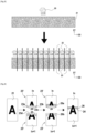
- this primary file 20 containing the complete functional image to be exposed, has a length greater than that of the exposure zone 2a, it then undergoes a cutting step during which the functional image 21 is cut into a plurality of secondary functional images 23, recorded in as many files 22, such that the length of each of the secondary images 23 is less than the length of the exposure zone 2a.
- the secondary images 23 are modified so as to provide an overlapping zone at the interface between each functional image: the secondary images 23 thus become technical images 23' comprising the desired functional image and additional technical elements.
- Such a step is shown schematically in the Figure 4 in a simplified case comprising only two secondary images I n and I n+1 . In practice, this step can be carried out jointly with the cutting step described above.
- patterns 24 are added to the functional image I n , near each of its upstream corners 23a, 23b. In the example shown, these patterns 24 are added beyond the upstream edge 23c of the functional image I n ; however, they could also be added within the framework of the functional image I n itself, in areas devoid of patterns to be transferred.
- the image I n+1 includes, in its metadata, the location of two calibration points 25, represented here schematically by circles but not intended to be exposed.
- the coordinates of these calibration points 25 correspond to the theoretical coordinates that the targets 24 should have in the frame of reference of the image I n+1 once the two images have been exposed one after the other so as to reform the primary image 21.
- an overlap zone 26 is provided between the two functional images I n and I n+1 by adding to the functional image I n+1 , along its downstream edge 23d, an image band 26b coming from the most upstream portion 26a of the image I n .
- the functional image I n is first exposed with its targets 24; the strip 10 then scrolls by a step corresponding to the length of the functional image I n ; the exposure device 6 then uses a vision device equipped with cameras 6b to locate the targets 24 and position the image I n+1 so as to make the calibration points 25 coincide with the targets 24; finally, the image I n+1 is exposed with its additional strip 26b which then overlaps with the downstream portion 26a of the image I n , thus forming an overlap zone 26 exposed twice.
- This example is of course simplified to facilitate understanding of the general principle of cutting and overlapping images.
- this example assumes that strip 10 is perfectly straight, which is rarely the case in practice.
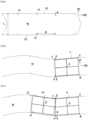
- the blank strip 10 has marks 11 regularly spaced along its two longitudinal edges 12.
- the pitch ⁇ between each mark 11 is regular and corresponds to the length y of the expected images.
- these may be holes made in the strip 10: this is particularly the case for the strips 10 intended to form the external layers of a stack of layers forming a multi-layer printed circuit.
- the images have a length y of 600 mm and a width x of 500 mm.
- the strip 10 then has a width L equal to 610 mm; the holes 11 are provided at a distance b from the edge 12 of the strip 10 equal to 3 mm and are spaced apart by a pitch ⁇ equal to 600 mm.
- the deformations of band 10 are deliberately exaggerated in order to better illustrate the point. In reality, the deformations are less than a millimeter. Furthermore, for the sake of simplification, it is considered in each of these figures that the alignment points of each image correspond to the four corners of the image considered; however, in practice, these alignment points may be located inside the image functional or beyond the edges of the functional image while preferably remaining close to the corners of the functional image.
- the first image I1 is positioned without distortion based on the first four holes A, B, C, D of the strip 10.
- the digital image preparation unit then calculates the position of the barycenter O of the quadrilateral ABCD and positions the image I1 so that its barycenter is positioned on this barycenter O; it then orients the image I1 around this point O by minimizing the average distance between the registration points of the image I1 and the holes A, B, C, D.
- targets E and F are also exposed at the level of the theoretical downstream calibration points of the following image, here in the upstream corners of the first image I1.
- FIG. 7 illustrates the positioning of image I n+1 relative to the previous image I n .
- image I n+1 is positioned without distortion based on the targets E and F of image I n and on the following holes A' and D' of strip 10.
- the digital image preparation unit calculates the position of the barycenter O' of the quadrilateral A'EFD' and positions image I n+1 so that its barycenter is positioned on this barycenter O'; it then orients image I n+1 around this point O' by minimizing the average distance between the calibration points of image I n+1 and points A', E, F, D'.
- the image I n+1 forms an angle ⁇ with the image I n .
- the larger the saber of the band 10 the larger the angle ⁇ and the smaller the length of the overlap zone will be at one of its ends, possibly leading to a gap between the two images as is the case here in this deliberately exaggerated example.
- FIG 8 illustrates a second example of a positioning method in which the strip 110 is identical to that of the first example. On the other hand, the positioning of the first image I1 is different.
- the digital image preparation unit distorts the first image I1 in order to position its four alignment points on the holes A, B, C, D of the strip 110, which results in the positioning of the first image I1.
- Targets E and F can also be exposed at the level of the theoretical downstream calibration points of the following image, i.e. here at the level of the upstream corners of the first image I1.
- FIG. 9 illustrates the positioning of image I n+1 relative to the previous image I n .
- the digital image preparation unit distorts image I n+1 in order to position its four alignment points on targets E and F of image I n and the following holes A', D' of strip 110. Targets E' and F' are also exposed in a similar manner.
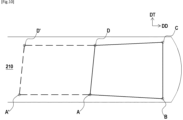
- FIG. 10 illustrates a third example of a positioning method in which the strip 210 is identical to that of the first example.
- the positioning of the first image I1 is for its part identical to that of the second example.
- the image I n+1 is positioned, after deformation, by positioning its alignment points on the four holes A', A, D, D' of the strip 210.
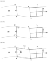
- FIGS 11A-11C illustrate a fourth example of a positioning method in which the strip 310 is identical to that of the first example and the positioning of the first image I1 is identical to that of the second example.
- the digital image preparation unit in order to position the image I n+1 , the digital image preparation unit first calculates the position of the center O' of the segment A'D'. Then, the digital image preparation unit calculates the position of two virtual targets Av' and Dv' by positioning the latter in such a way that the segment Av'Dv' extends in the transverse direction DT, has O' as its center, and has a length equal to the distance separating the two registration points of the image I n+1 . The image I n+1 is then deformed in order to position its four registration points on the four points Av', E, F, Dv', which results in the positioning of the image I n+1 relative to the image I n .
- THE figures 12 to 15 illustrate a fifth example of a positioning method.
- the strip 410 is different: it is in fact devoid of any prior marking. This is particularly the case for the strips 410 intended to form the internal layers of a stack of layers forming a multi-layer printed circuit.
- the vision device comprises two cameras capable of moving and positioning themselves at predetermined coordinates as a function of the length y and the width x of the images.
- the vision device is then capable of detecting the edge 412 of the strip 410 in the field 406c of each of the cameras: it then determines the coordinates of the points A, B, C, D located, for each camera, at the intersection of the strip edge 412 and the median segment of the field 406c of the camera.
- the vision device calculates the coordinates of virtual sights A', B', C', D' by positioning them at a predetermined distance e, here equal to 10 mm, inside the strip 410 in the transverse direction DT.
- the first image I1 can then be positioned based on these four virtual targets A', B', C', D' according to one of the methods presented above, for example according to the method without deformation of the first example.
- FIG. 15 illustrates the positioning of image I n+1 relative to the previous image I n .
- the digital image preparation unit positions image I n+1 , without distortion, by positioning its downstream calibration points on targets G and J of image I n .
- Targets G', H', I' and J' are also exposed in a similar manner.
- the image I n+1 is positioned in the extension of the image I n . Therefore, depending on the importance of the deformation of the band 410, it is possible that the image I n+1 positioned in this way comes out of the band 410 as shown in the figure 16 . In this regard, it is however of course recalled that the deformation of the band 510 is greatly exaggerated in the figures so that such band exits remain in practice limited in frequency and amplitude.
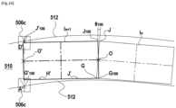
- FIG 16 illustrates a sixth example of a positioning method in which the strip 510 and the positioning of the first image I1 are identical to those of the fifth example.
- the vision device two cameras of which are positioned at the theoretical location of the upstream end of the image I n+1 , detects the edge 512 of the strip 510 in the field 506c of these two cameras: it then determines the coordinates of the points A' and D' located, for each camera, at the intersection of the edge of the strip 512 and the median segment of the field 506c of the camera.
- the digital image preparation unit then calculates, on the one hand, the position of the center O of the segment GJ and, on the other hand, the position of the center O' of the segment A'D'.
- the line OO' then defines the orientation of the image I n+1 .
- the digital image preparation unit calculates the position of two virtual targets G 100 , J 100 by positioning the latter in such a way that the segment G 100 , J 100 is perpendicular to the line OO', has O as its center, and has a length equal to the distance separating the two calibration points of the image I n+1 .
- the digital image preparation unit calculates the position of two other virtual targets G' 100 , J' 100 by positioning the latter in such a way that the segment G' 100 , J' 100 is perpendicular to the line OO', has O' as its center, and has a length equal to the distance separating the two calibration points of the image I n+1 .
- the image I n+1 is then positioned, without deformation, by positioning its four calibration points on the four points G' 100 , G 100 , J 100 and J' 100 .
- Targets are also exposed at the points G' 100 and J' 100 ; targets H', J' intended for front-back alignment are also exposed in a similar manner.
- the digital image preparation unit calculates both the coordinates of points G, J, G' and J' according to the fifth example and the coordinates of points G 100 , J 100 , G' 100 and J' 100 according to the sixth example.
- the digital image preparation unit then applies a weighting factor s to these two sets of extreme coordinates in the following manner in order to obtain the coordinates of the four virtual targets to be kept Gv, Jv, G'v and J'v:
- This weighting coefficient s can be determined in different ways: predetermined according to the type of application targeted, selected by the user from several pre-recorded settings, entered manually or even calculated from another parameter.
Landscapes
- Physics & Mathematics (AREA)
- General Physics & Mathematics (AREA)
- Life Sciences & Earth Sciences (AREA)
- Sustainable Development (AREA)
- Exposure And Positioning Against Photoresist Photosensitive Materials (AREA)
- Projection-Type Copiers In General (AREA)
Claims (10)
- Verfahren, durchgeführt von einem Computer, für die Bildvorbereitung für eine Bandbelichtungsmaschine, wobei die Maschine (1) konfiguriert ist, um anhand einer oder mehrerer digitaler Dateien (22) eine Abfolge von Bildern (23) nacheinander auf ein Band (10) zu projizieren, das in einer Laufrichtung (DD) der Maschine (1) läuft,
wobei ein Überlappungsbereich (26) auf dem belichteten Band (10) zwischen dem Bild n+1 (In+1) und dem unmittelbar davor projizierten Bild n (In) gewährleistet wird, dadurch gekennzeichnet, dass dem Bild n (In) in der Nähe seiner zwei stromaufwärtigen Ecken (23a, 23b) Positionsmarkierungen (24) hinzugefügt werden, die zum Positionieren des Bilds n+1 (In+1) verwendet werden. - Verfahren nach Anspruch 1, umfassend einen Schritt eines Zerschneidens eines primären digitalen Bilds (21) in eine Vielzahl von sekundären digitalen Bildern (23) geringerer Länge, wobei diese Vielzahl von sekundären digitalen Bildern (23) die Abfolge von Bildern bildet.
- Verfahren nach Anspruch 1 oder 2, wobei dem Bild n+1 (In+1) über seinen ursprünglichen stromabwärtigen Rand (23d) hinaus einen Bildabschnitt (23b) hinzugefügt wird, der von dem stromaufwärtigen Rand (23a) des Bilds n (In) stammt, oder dem Bild n (In) über seinen ursprünglichen stromaufwärtigen Rand hinaus einen Bildabschnitt hinzugefügt wird, der von dem stromabwärtigen Rand des Bilds n+1 (In+1) stammt.
- Verfahren nach einem der Ansprüche 1 bis 3, wobei der Überlappungsbereich (26) im Durchschnitt über die Breite der Grenzfläche zwischen dem Bild n+1 (In+1) und dem Bild n (In) eine Länge zwischen 10 und 200 µm, vorzugsweise zwischen 50 und 150 µm, bevorzugter zwischen 80 und 100 µm, besitzt.
- Verfahren nach einem der Ansprüche 1 bis 4, wobei das Bild n+1 (In+1) verzerrungsfrei basierend auf mindestens zwei Testmustern (24) des Bands (10) positioniert wird.
- Verfahren nach einem der Ansprüche 1 bis 4, wobei das Bild n+1 (In+1) unter eventueller Verzerrung positioniert wird, um vier vorbestimmte Punkte des Bilds mit vier Positionsmarkierungen (A', E, F, D') des Bands (210) in Übereinstimmung zu bringen.
- Verfahren nach einem der Ansprüche 1 bis 6, wobei das Bild n+1 (In+1) basierend auf zwei realen Positionsmarkierungen (E, F), die mit dem Bild n (In) belichtet sind, und zwei realen Positionsmarkierungen (A', D') des Bands (10) positioniert wird.
- Verfahren nach einem der Ansprüche 1 bis 6, wobei das Bild n+1 (In+1) basierend auf zwei realen Positionsmarkierungen (E, F), die mit dem Bild n (In) belichtet sind, und zwei virtuellen Positionsmarkierungen (G'100; J'100), die aus der Randerfassung (612) des Bands (610) stammen, positioniert wird.
- Bandbelichtungsmaschine, umfassend einen Träger (2), der einen Belichtungsbereich (2a) aufweist,eine Belichtungsanordnung (6), die gegenüber dem Belichtungsbereich (2a) des Trägers (2) bereitgestellt ist, umfassend mindestens eine Lichtquelle und mindestens eine Projektionsvorrichtung, die konfiguriert ist, um anhand einer oder mehrerer digitaler Dateien (22) eine Abfolge von Bildern (23) in den Belichtungsbereich (2a) zu projizieren,eine Führungs- und Antriebsvorrichtung (4) für ein Band (10), die konfiguriert ist, um ein Band (10) auf dem Träger (2) zu spannen und es in einer Laufrichtung (DD) zu bewegen, die durch den Belichtungsbereich (2a) verläuft, undeine digitale Bildvorbereitungseinheit, die konfiguriert ist, um ein Bild (23) vor seiner Projektion durch die Projektionsvorrichtung zu positionieren, auszurichten, zu modifizieren und/oder zu verzerren,wobei die digitale Bildvorbereitungseinheit konfiguriert ist, um ein Bildvorbereitungsverfahren nach einem der vorherigen Ansprüche durchzuführen.
- Computerprogramm, umfassend Anweisungen zum Ausführen der Schritte des Bildvorbereitungsverfahrens nach einem der Ansprüche 1 bis 8.
Applications Claiming Priority (1)
| Application Number | Priority Date | Filing Date | Title |
|---|---|---|---|
| FR2102121A FR3120454A1 (fr) | 2021-03-04 | 2021-03-04 | Préparation d’image pour machine d’insolation de bande |
Publications (2)
| Publication Number | Publication Date |
|---|---|
| EP4053635A1 EP4053635A1 (de) | 2022-09-07 |
| EP4053635B1 true EP4053635B1 (de) | 2025-06-25 |
Family
ID=75539575
Family Applications (1)
| Application Number | Title | Priority Date | Filing Date |
|---|---|---|---|
| EP22159798.2A Active EP4053635B1 (de) | 2021-03-04 | 2022-03-02 | Bildvorbereitung für bandbelichtungsmaschine und bandbelichtungsmaschine |
Country Status (2)
| Country | Link |
|---|---|
| EP (1) | EP4053635B1 (de) |
| FR (1) | FR3120454A1 (de) |
Family Cites Families (5)
| Publication number | Priority date | Publication date | Assignee | Title |
|---|---|---|---|---|
| JP3648516B2 (ja) * | 1999-02-05 | 2005-05-18 | ペンタックスインダストリアルインスツルメンツ株式会社 | 走査式描画装置 |
| JP2001030532A (ja) * | 1999-05-19 | 2001-02-06 | Fuji Photo Film Co Ltd | プリント画像形成方法及び装置 |
| JP4491311B2 (ja) * | 2004-09-30 | 2010-06-30 | 富士フイルム株式会社 | 画像記録装置及び画像記録方法 |
| US7375795B2 (en) * | 2004-12-22 | 2008-05-20 | Asml Netherlands B.V. | Lithographic apparatus, device manufacturing method, and device manufactured thereby |
| KR20120116918A (ko) * | 2010-02-02 | 2012-10-23 | 가부시키가이샤 니콘 | 노광방법, 노광장치, 패턴형성방법 및 디바이스 제조방법 |
-
2021
- 2021-03-04 FR FR2102121A patent/FR3120454A1/fr active Pending
-
2022
- 2022-03-02 EP EP22159798.2A patent/EP4053635B1/de active Active
Also Published As
| Publication number | Publication date |
|---|---|
| EP4053635A1 (de) | 2022-09-07 |
| FR3120454A1 (fr) | 2022-09-09 |
Similar Documents
| Publication | Publication Date | Title |
|---|---|---|
| RU2458798C2 (ru) | Способ и установка для нанесения пленочного материала на последовательно перемещаемые листы | |
| BE1006796A5 (fr) | Appareil et procede pour maintenir la synchronisation des perforations. | |
| EP1132203A1 (de) | Verfahren und Vorrichtung zum automatischen Voreinstellen des Registers von Rotationsdruckmaschinen | |
| FR2712231A1 (fr) | Maintien de la synchronisation des perforations dans une machine de fabrication de sacs en matière plastique ou équivalents. | |
| JP6638835B2 (ja) | 基板処理装置 | |
| FR2753131A1 (fr) | Dispositif pour travailler sur des feuilles d'un materiau en feuilles et materiau en feuilles destine a etre utilise avec ce dispositif | |
| FR2702998A1 (fr) | Installation pour l'impression feuille à feuille et ligne d'impression correspondante. | |
| JP6004157B2 (ja) | 3次元液晶表示装置の製造装置及び製造方法 | |
| EP4053635A1 (de) | Bildvorbereitung für bandbelichtungsmaschine und bandbelichtungsmaschine | |
| FR2621713A1 (fr) | Procede et appareil d'enregistrement d'informations d'images en couleurs | |
| JP5685756B2 (ja) | フィルム露光方法 | |
| FR2691814A1 (fr) | Procédé et appareillage d'impression d'une image. | |
| FR2969531A1 (fr) | Dispositif de rainurage d'une feuille mince | |
| FR2732642A1 (fr) | Procede de formation d'un ruban d'image graphique | |
| EP2039525A1 (de) | Verfahren zum Bedrucken einer linsenförmigen Karte, bedruckte linsenförmige Karte und Drucker für linsenförmige Karten | |
| WO2022008058A1 (fr) | Machine et procédé pour l'impression à haute cadence de titres sécurisés | |
| JP2017194370A (ja) | ウェブ欠陥検査装置 | |
| FR2504062A1 (fr) | Duplicateur d'impression offset en couleurs tramees | |
| JP6486252B2 (ja) | エッジセンサ | |
| JP2019109546A (ja) | 基板処理装置 | |
| JP2018055122A (ja) | 基板処理装置 | |
| JPH0287145A (ja) | オペーク装置 | |
| FR3097468A1 (fr) | Machine et procede pour l’impression a haute cadence de titres securises | |
| JP3305865B2 (ja) | 印画紙搬送方法及び写真焼付装置 | |
| JP2003295333A (ja) | 振分装置 |
Legal Events
| Date | Code | Title | Description |
|---|---|---|---|
| PUAI | Public reference made under article 153(3) epc to a published international application that has entered the european phase |
Free format text: ORIGINAL CODE: 0009012 |
|
| STAA | Information on the status of an ep patent application or granted ep patent |
Free format text: STATUS: THE APPLICATION HAS BEEN PUBLISHED |
|
| AK | Designated contracting states |
Kind code of ref document: A1 Designated state(s): AL AT BE BG CH CY CZ DE DK EE ES FI FR GB GR HR HU IE IS IT LI LT LU LV MC MK MT NL NO PL PT RO RS SE SI SK SM TR |
|
| STAA | Information on the status of an ep patent application or granted ep patent |
Free format text: STATUS: REQUEST FOR EXAMINATION WAS MADE |
|
| 17P | Request for examination filed |
Effective date: 20230307 |
|
| RBV | Designated contracting states (corrected) |
Designated state(s): AL AT BE BG CH CY CZ DE DK EE ES FI FR GB GR HR HU IE IS IT LI LT LU LV MC MK MT NL NO PL PT RO RS SE SI SK SM TR |
|
| GRAP | Despatch of communication of intention to grant a patent |
Free format text: ORIGINAL CODE: EPIDOSNIGR1 |
|
| STAA | Information on the status of an ep patent application or granted ep patent |
Free format text: STATUS: GRANT OF PATENT IS INTENDED |
|
| INTG | Intention to grant announced |
Effective date: 20250116 |
|
| GRAS | Grant fee paid |
Free format text: ORIGINAL CODE: EPIDOSNIGR3 |
|
| GRAA | (expected) grant |
Free format text: ORIGINAL CODE: 0009210 |
|
| STAA | Information on the status of an ep patent application or granted ep patent |
Free format text: STATUS: THE PATENT HAS BEEN GRANTED |
|
| AK | Designated contracting states |
Kind code of ref document: B1 Designated state(s): AL AT BE BG CH CY CZ DE DK EE ES FI FR GB GR HR HU IE IS IT LI LT LU LV MC MK MT NL NO PL PT RO RS SE SI SK SM TR |
|
| REG | Reference to a national code |
Ref country code: GB Ref legal event code: FG4D Free format text: NOT ENGLISH |
|
| REG | Reference to a national code |
Ref country code: CH Ref legal event code: EP |
|
| REG | Reference to a national code |
Ref country code: CH Ref legal event code: EP |
|
| REG | Reference to a national code |
Ref country code: IE Ref legal event code: FG4D Free format text: LANGUAGE OF EP DOCUMENT: FRENCH |
|
| REG | Reference to a national code |
Ref country code: DE Ref legal event code: R096 Ref document number: 602022016279 Country of ref document: DE |
|
| PG25 | Lapsed in a contracting state [announced via postgrant information from national office to epo] |
Ref country code: FI Free format text: LAPSE BECAUSE OF FAILURE TO SUBMIT A TRANSLATION OF THE DESCRIPTION OR TO PAY THE FEE WITHIN THE PRESCRIBED TIME-LIMIT Effective date: 20250625 |
|
| REG | Reference to a national code |
Ref country code: LT Ref legal event code: MG9D |
|
| PG25 | Lapsed in a contracting state [announced via postgrant information from national office to epo] |
Ref country code: NO Free format text: LAPSE BECAUSE OF FAILURE TO SUBMIT A TRANSLATION OF THE DESCRIPTION OR TO PAY THE FEE WITHIN THE PRESCRIBED TIME-LIMIT Effective date: 20250925 Ref country code: GR Free format text: LAPSE BECAUSE OF FAILURE TO SUBMIT A TRANSLATION OF THE DESCRIPTION OR TO PAY THE FEE WITHIN THE PRESCRIBED TIME-LIMIT Effective date: 20250926 |
|
| PG25 | Lapsed in a contracting state [announced via postgrant information from national office to epo] |
Ref country code: BG Free format text: LAPSE BECAUSE OF FAILURE TO SUBMIT A TRANSLATION OF THE DESCRIPTION OR TO PAY THE FEE WITHIN THE PRESCRIBED TIME-LIMIT Effective date: 20250625 |
|
| PG25 | Lapsed in a contracting state [announced via postgrant information from national office to epo] |
Ref country code: HR Free format text: LAPSE BECAUSE OF FAILURE TO SUBMIT A TRANSLATION OF THE DESCRIPTION OR TO PAY THE FEE WITHIN THE PRESCRIBED TIME-LIMIT Effective date: 20250625 |
|
| PG25 | Lapsed in a contracting state [announced via postgrant information from national office to epo] |
Ref country code: RS Free format text: LAPSE BECAUSE OF FAILURE TO SUBMIT A TRANSLATION OF THE DESCRIPTION OR TO PAY THE FEE WITHIN THE PRESCRIBED TIME-LIMIT Effective date: 20250925 |
|
| PG25 | Lapsed in a contracting state [announced via postgrant information from national office to epo] |
Ref country code: LV Free format text: LAPSE BECAUSE OF FAILURE TO SUBMIT A TRANSLATION OF THE DESCRIPTION OR TO PAY THE FEE WITHIN THE PRESCRIBED TIME-LIMIT Effective date: 20250625 |
|
| REG | Reference to a national code |
Ref country code: NL Ref legal event code: MP Effective date: 20250625 |
|
| PG25 | Lapsed in a contracting state [announced via postgrant information from national office to epo] |
Ref country code: NL Free format text: LAPSE BECAUSE OF FAILURE TO SUBMIT A TRANSLATION OF THE DESCRIPTION OR TO PAY THE FEE WITHIN THE PRESCRIBED TIME-LIMIT Effective date: 20250625 |
|
| PG25 | Lapsed in a contracting state [announced via postgrant information from national office to epo] |
Ref country code: PT Free format text: LAPSE BECAUSE OF FAILURE TO SUBMIT A TRANSLATION OF THE DESCRIPTION OR TO PAY THE FEE WITHIN THE PRESCRIBED TIME-LIMIT Effective date: 20251027 |
|
| REG | Reference to a national code |
Ref country code: AT Ref legal event code: MK05 Ref document number: 1807081 Country of ref document: AT Kind code of ref document: T Effective date: 20250625 |
|
| PG25 | Lapsed in a contracting state [announced via postgrant information from national office to epo] |
Ref country code: IS Free format text: LAPSE BECAUSE OF FAILURE TO SUBMIT A TRANSLATION OF THE DESCRIPTION OR TO PAY THE FEE WITHIN THE PRESCRIBED TIME-LIMIT Effective date: 20251025 |
|
| PG25 | Lapsed in a contracting state [announced via postgrant information from national office to epo] |
Ref country code: AT Free format text: LAPSE BECAUSE OF FAILURE TO SUBMIT A TRANSLATION OF THE DESCRIPTION OR TO PAY THE FEE WITHIN THE PRESCRIBED TIME-LIMIT Effective date: 20250625 Ref country code: SM Free format text: LAPSE BECAUSE OF FAILURE TO SUBMIT A TRANSLATION OF THE DESCRIPTION OR TO PAY THE FEE WITHIN THE PRESCRIBED TIME-LIMIT Effective date: 20250625 |
|
| PG25 | Lapsed in a contracting state [announced via postgrant information from national office to epo] |
Ref country code: CZ Free format text: LAPSE BECAUSE OF FAILURE TO SUBMIT A TRANSLATION OF THE DESCRIPTION OR TO PAY THE FEE WITHIN THE PRESCRIBED TIME-LIMIT Effective date: 20250625 |
|
| PG25 | Lapsed in a contracting state [announced via postgrant information from national office to epo] |
Ref country code: PL Free format text: LAPSE BECAUSE OF FAILURE TO SUBMIT A TRANSLATION OF THE DESCRIPTION OR TO PAY THE FEE WITHIN THE PRESCRIBED TIME-LIMIT Effective date: 20250625 |
|
| PG25 | Lapsed in a contracting state [announced via postgrant information from national office to epo] |
Ref country code: EE Free format text: LAPSE BECAUSE OF FAILURE TO SUBMIT A TRANSLATION OF THE DESCRIPTION OR TO PAY THE FEE WITHIN THE PRESCRIBED TIME-LIMIT Effective date: 20250625 |
|
| PG25 | Lapsed in a contracting state [announced via postgrant information from national office to epo] |
Ref country code: SK Free format text: LAPSE BECAUSE OF FAILURE TO SUBMIT A TRANSLATION OF THE DESCRIPTION OR TO PAY THE FEE WITHIN THE PRESCRIBED TIME-LIMIT Effective date: 20250625 |
|
| PG25 | Lapsed in a contracting state [announced via postgrant information from national office to epo] |
Ref country code: ES Free format text: LAPSE BECAUSE OF FAILURE TO SUBMIT A TRANSLATION OF THE DESCRIPTION OR TO PAY THE FEE WITHIN THE PRESCRIBED TIME-LIMIT Effective date: 20250625 |
|
| PGFP | Annual fee paid to national office [announced via postgrant information from national office to epo] |
Ref country code: GB Payment date: 20260331 Year of fee payment: 5 |
|
| PG25 | Lapsed in a contracting state [announced via postgrant information from national office to epo] |
Ref country code: DK Free format text: LAPSE BECAUSE OF FAILURE TO SUBMIT A TRANSLATION OF THE DESCRIPTION OR TO PAY THE FEE WITHIN THE PRESCRIBED TIME-LIMIT Effective date: 20250625 |
|
| PG25 | Lapsed in a contracting state [announced via postgrant information from national office to epo] |
Ref country code: IT Free format text: LAPSE BECAUSE OF FAILURE TO SUBMIT A TRANSLATION OF THE DESCRIPTION OR TO PAY THE FEE WITHIN THE PRESCRIBED TIME-LIMIT Effective date: 20250625 |
|
| PGFP | Annual fee paid to national office [announced via postgrant information from national office to epo] |
Ref country code: FR Payment date: 20260323 Year of fee payment: 5 |
|
| PLBE | No opposition filed within time limit |
Free format text: ORIGINAL CODE: 0009261 |
|
| STAA | Information on the status of an ep patent application or granted ep patent |
Free format text: STATUS: NO OPPOSITION FILED WITHIN TIME LIMIT |
|
| REG | Reference to a national code |
Ref country code: CH Ref legal event code: L10 Free format text: ST27 STATUS EVENT CODE: U-0-0-L10-L00 (AS PROVIDED BY THE NATIONAL OFFICE) Effective date: 20260507 |