EP4053545A1 - Dispositifs et compositions à base de super-réseau photonique destinés à être utilisés en imagerie par luminescence, et leurs procédés d'utilisation - Google Patents
Dispositifs et compositions à base de super-réseau photonique destinés à être utilisés en imagerie par luminescence, et leurs procédés d'utilisation Download PDFInfo
- Publication number
- EP4053545A1 EP4053545A1 EP22164882.7A EP22164882A EP4053545A1 EP 4053545 A1 EP4053545 A1 EP 4053545A1 EP 22164882 A EP22164882 A EP 22164882A EP 4053545 A1 EP4053545 A1 EP 4053545A1
- Authority
- EP
- European Patent Office
- Prior art keywords
- luminophore
- wavelength
- angle
- photonic superlattice
- nucleic acid
- Prior art date
- Legal status (The legal status is an assumption and is not a legal conclusion. Google has not performed a legal analysis and makes no representation as to the accuracy of the status listed.)
- Pending
Links
- 239000000203 mixture Substances 0.000 title claims description 175
- 238000000034 method Methods 0.000 title claims description 95
- 238000003384 imaging method Methods 0.000 title abstract description 30
- 239000000463 material Substances 0.000 claims abstract description 319
- 230000003287 optical effect Effects 0.000 claims abstract description 115
- 238000004020 luminiscence type Methods 0.000 claims abstract description 94
- 102000039446 nucleic acids Human genes 0.000 claims description 224
- 108020004707 nucleic acids Proteins 0.000 claims description 224
- 150000007523 nucleic acids Chemical class 0.000 claims description 224
- 102000040430 polynucleotide Human genes 0.000 claims description 151
- 108091033319 polynucleotide Proteins 0.000 claims description 151
- 239000002157 polynucleotide Substances 0.000 claims description 151
- 230000008878 coupling Effects 0.000 claims description 14
- 238000010168 coupling process Methods 0.000 claims description 14
- 238000005859 coupling reaction Methods 0.000 claims description 14
- 230000002401 inhibitory effect Effects 0.000 claims 3
- 230000001902 propagating effect Effects 0.000 abstract description 36
- 230000005855 radiation Effects 0.000 description 72
- 230000005284 excitation Effects 0.000 description 45
- 239000012491 analyte Substances 0.000 description 42
- 125000003729 nucleotide group Chemical group 0.000 description 40
- 239000002773 nucleotide Substances 0.000 description 38
- 230000000295 complement effect Effects 0.000 description 29
- 229920000642 polymer Polymers 0.000 description 24
- 239000011521 glass Substances 0.000 description 22
- 108020004414 DNA Proteins 0.000 description 21
- 102000053602 DNA Human genes 0.000 description 21
- 238000009826 distribution Methods 0.000 description 20
- 239000000499 gel Substances 0.000 description 19
- 239000007788 liquid Substances 0.000 description 18
- 239000004038 photonic crystal Substances 0.000 description 17
- 239000003989 dielectric material Substances 0.000 description 15
- 239000012530 fluid Substances 0.000 description 14
- 238000012163 sequencing technique Methods 0.000 description 13
- UYTPUPDQBNUYGX-UHFFFAOYSA-N Guanine Natural products O=C1NC(N)=NC2=C1N=CN2 UYTPUPDQBNUYGX-UHFFFAOYSA-N 0.000 description 11
- 239000004065 semiconductor Substances 0.000 description 11
- 239000011295 pitch Substances 0.000 description 10
- 239000012780 transparent material Substances 0.000 description 10
- 230000003595 spectral effect Effects 0.000 description 9
- 230000000737 periodic effect Effects 0.000 description 8
- 238000001514 detection method Methods 0.000 description 7
- 239000000758 substrate Substances 0.000 description 7
- 238000006243 chemical reaction Methods 0.000 description 6
- 108090000623 proteins and genes Proteins 0.000 description 6
- 239000011347 resin Substances 0.000 description 6
- 229920005989 resin Polymers 0.000 description 6
- 229920002477 rna polymer Polymers 0.000 description 6
- 239000000126 substance Substances 0.000 description 6
- 238000000411 transmission spectrum Methods 0.000 description 6
- VYPSYNLAJGMNEJ-UHFFFAOYSA-N Silicium dioxide Chemical compound O=[Si]=O VYPSYNLAJGMNEJ-UHFFFAOYSA-N 0.000 description 5
- 239000000975 dye Substances 0.000 description 5
- 238000010208 microarray analysis Methods 0.000 description 5
- 238000001127 nanoimprint lithography Methods 0.000 description 5
- -1 polypropylene Polymers 0.000 description 5
- 239000007787 solid Substances 0.000 description 5
- PBCFLUZVCVVTBY-UHFFFAOYSA-N tantalum pentoxide Inorganic materials O=[Ta](=O)O[Ta](=O)=O PBCFLUZVCVVTBY-UHFFFAOYSA-N 0.000 description 5
- 210000004027 cell Anatomy 0.000 description 4
- GYOZYWVXFNDGLU-XLPZGREQSA-N dTMP Chemical compound O=C1NC(=O)C(C)=CN1[C@@H]1O[C@H](COP(O)(O)=O)[C@@H](O)C1 GYOZYWVXFNDGLU-XLPZGREQSA-N 0.000 description 4
- 239000000017 hydrogel Substances 0.000 description 4
- 230000003993 interaction Effects 0.000 description 4
- 102000004169 proteins and genes Human genes 0.000 description 4
- ZKHQWZAMYRWXGA-KQYNXXCUSA-J ATP(4-) Chemical compound C1=NC=2C(N)=NC=NC=2N1[C@@H]1O[C@H](COP([O-])(=O)OP([O-])(=O)OP([O-])([O-])=O)[C@@H](O)[C@H]1O ZKHQWZAMYRWXGA-KQYNXXCUSA-J 0.000 description 3
- 229930024421 Adenine Natural products 0.000 description 3
- ZKHQWZAMYRWXGA-UHFFFAOYSA-N Adenosine triphosphate Natural products C1=NC=2C(N)=NC=NC=2N1C1OC(COP(O)(=O)OP(O)(=O)OP(O)(O)=O)C(O)C1O ZKHQWZAMYRWXGA-UHFFFAOYSA-N 0.000 description 3
- PCDQPRRSZKQHHS-CCXZUQQUSA-N Cytarabine Triphosphate Chemical compound O=C1N=C(N)C=CN1[C@H]1[C@@H](O)[C@H](O)[C@@H](COP(O)(=O)OP(O)(=O)OP(O)(O)=O)O1 PCDQPRRSZKQHHS-CCXZUQQUSA-N 0.000 description 3
- XKMLYUALXHKNFT-UUOKFMHZSA-N Guanosine-5'-triphosphate Chemical compound C1=2NC(N)=NC(=O)C=2N=CN1[C@@H]1O[C@H](COP(O)(=O)OP(O)(=O)OP(O)(O)=O)[C@@H](O)[C@H]1O XKMLYUALXHKNFT-UUOKFMHZSA-N 0.000 description 3
- 108020004682 Single-Stranded DNA Proteins 0.000 description 3
- RZCIEJXAILMSQK-JXOAFFINSA-N TTP Chemical compound O=C1NC(=O)C(C)=CN1[C@H]1[C@H](O)[C@H](O)[C@@H](COP(O)(=O)OP(O)(=O)OP(O)(O)=O)O1 RZCIEJXAILMSQK-JXOAFFINSA-N 0.000 description 3
- ISAKRJDGNUQOIC-UHFFFAOYSA-N Uracil Natural products O=C1C=CNC(=O)N1 ISAKRJDGNUQOIC-UHFFFAOYSA-N 0.000 description 3
- 229960000643 adenine Drugs 0.000 description 3
- OPTASPLRGRRNAP-UHFFFAOYSA-N cytosine Natural products NC=1C=CNC(=O)N=1 OPTASPLRGRRNAP-UHFFFAOYSA-N 0.000 description 3
- 238000013461 design Methods 0.000 description 3
- 238000002189 fluorescence spectrum Methods 0.000 description 3
- 239000007850 fluorescent dye Substances 0.000 description 3
- 238000005286 illumination Methods 0.000 description 3
- 230000001788 irregular Effects 0.000 description 3
- 238000005457 optimization Methods 0.000 description 3
- 238000000059 patterning Methods 0.000 description 3
- 238000000206 photolithography Methods 0.000 description 3
- 229940035893 uracil Drugs 0.000 description 3
- KHWCHTKSEGGWEX-RRKCRQDMSA-N 2'-deoxyadenosine 5'-monophosphate Chemical compound C1=NC=2C(N)=NC=NC=2N1[C@H]1C[C@H](O)[C@@H](COP(O)(O)=O)O1 KHWCHTKSEGGWEX-RRKCRQDMSA-N 0.000 description 2
- LTFMZDNNPPEQNG-KVQBGUIXSA-N 2'-deoxyguanosine 5'-monophosphate Chemical compound C1=2NC(N)=NC(=O)C=2N=CN1[C@H]1C[C@H](O)[C@@H](COP(O)(O)=O)O1 LTFMZDNNPPEQNG-KVQBGUIXSA-N 0.000 description 2
- FZWGECJQACGGTI-UHFFFAOYSA-N 2-amino-7-methyl-1,7-dihydro-6H-purin-6-one Chemical class NC1=NC(O)=C2N(C)C=NC2=N1 FZWGECJQACGGTI-UHFFFAOYSA-N 0.000 description 2
- XTWYTFMLZFPYCI-KQYNXXCUSA-N 5'-adenylphosphoric acid Chemical compound C1=NC=2C(N)=NC=NC=2N1[C@@H]1O[C@H](COP(O)(=O)OP(O)(O)=O)[C@@H](O)[C@H]1O XTWYTFMLZFPYCI-KQYNXXCUSA-N 0.000 description 2
- RYVNIFSIEDRLSJ-UHFFFAOYSA-N 5-(hydroxymethyl)cytosine Chemical compound NC=1NC(=O)N=CC=1CO RYVNIFSIEDRLSJ-UHFFFAOYSA-N 0.000 description 2
- PEHVGBZKEYRQSX-UHFFFAOYSA-N 7-deaza-adenine Chemical class NC1=NC=NC2=C1C=CN2 PEHVGBZKEYRQSX-UHFFFAOYSA-N 0.000 description 2
- HCGHYQLFMPXSDU-UHFFFAOYSA-N 7-methyladenine Chemical class C1=NC(N)=C2N(C)C=NC2=N1 HCGHYQLFMPXSDU-UHFFFAOYSA-N 0.000 description 2
- GFFGJBXGBJISGV-UHFFFAOYSA-N Adenine Chemical compound NC1=NC=NC2=C1N=CN2 GFFGJBXGBJISGV-UHFFFAOYSA-N 0.000 description 2
- XTWYTFMLZFPYCI-UHFFFAOYSA-N Adenosine diphosphate Natural products C1=NC=2C(N)=NC=NC=2N1C1OC(COP(O)(=O)OP(O)(O)=O)C(O)C1O XTWYTFMLZFPYCI-UHFFFAOYSA-N 0.000 description 2
- XKRFYHLGVUSROY-UHFFFAOYSA-N Argon Chemical compound [Ar] XKRFYHLGVUSROY-UHFFFAOYSA-N 0.000 description 2
- IJGRMHOSHXDMSA-UHFFFAOYSA-N Atomic nitrogen Chemical compound N#N IJGRMHOSHXDMSA-UHFFFAOYSA-N 0.000 description 2
- ZWIADYZPOWUWEW-XVFCMESISA-N CDP Chemical compound O=C1N=C(N)C=CN1[C@H]1[C@H](O)[C@H](O)[C@@H](COP(O)(=O)OP(O)(O)=O)O1 ZWIADYZPOWUWEW-XVFCMESISA-N 0.000 description 2
- AHCYMLUZIRLXAA-SHYZEUOFSA-N Deoxyuridine 5'-triphosphate Chemical compound O1[C@H](COP(O)(=O)OP(O)(=O)OP(O)(O)=O)[C@@H](O)C[C@@H]1N1C(=O)NC(=O)C=C1 AHCYMLUZIRLXAA-SHYZEUOFSA-N 0.000 description 2
- 108091060211 Expressed sequence tag Proteins 0.000 description 2
- QGWNDRXFNXRZMB-UUOKFMHZSA-N GDP Chemical compound C1=2NC(N)=NC(=O)C=2N=CN1[C@@H]1O[C@H](COP(O)(=O)OP(O)(O)=O)[C@@H](O)[C@H]1O QGWNDRXFNXRZMB-UUOKFMHZSA-N 0.000 description 2
- PPBRXRYQALVLMV-UHFFFAOYSA-N Styrene Chemical compound C=CC1=CC=CC=C1 PPBRXRYQALVLMV-UHFFFAOYSA-N 0.000 description 2
- XCCTYIAWTASOJW-XVFCMESISA-N Uridine-5'-Diphosphate Chemical compound O[C@@H]1[C@H](O)[C@@H](COP(O)(=O)OP(O)(O)=O)O[C@H]1N1C(=O)NC(=O)C=C1 XCCTYIAWTASOJW-XVFCMESISA-N 0.000 description 2
- DJJCXFVJDGTHFX-UHFFFAOYSA-N Uridinemonophosphate Natural products OC1C(O)C(COP(O)(O)=O)OC1N1C(=O)NC(=O)C=C1 DJJCXFVJDGTHFX-UHFFFAOYSA-N 0.000 description 2
- BZDVTEPMYMHZCR-JGVFFNPUSA-N [(2s,5r)-5-(5-methyl-2,4-dioxopyrimidin-1-yl)oxolan-2-yl]methyl phosphono hydrogen phosphate Chemical compound O=C1NC(=O)C(C)=CN1[C@@H]1O[C@H](COP(O)(=O)OP(O)(O)=O)CC1 BZDVTEPMYMHZCR-JGVFFNPUSA-N 0.000 description 2
- 238000010521 absorption reaction Methods 0.000 description 2
- 238000005253 cladding Methods 0.000 description 2
- 229940104302 cytosine Drugs 0.000 description 2
- DAEAPNUQQAICNR-RRKCRQDMSA-K dADP(3-) Chemical compound C1=NC=2C(N)=NC=NC=2N1[C@H]1C[C@H](O)[C@@H](COP([O-])(=O)OP([O-])([O-])=O)O1 DAEAPNUQQAICNR-RRKCRQDMSA-K 0.000 description 2
- SUYVUBYJARFZHO-RRKCRQDMSA-N dATP Chemical compound C1=NC=2C(N)=NC=NC=2N1[C@H]1C[C@H](O)[C@@H](COP(O)(=O)OP(O)(=O)OP(O)(O)=O)O1 SUYVUBYJARFZHO-RRKCRQDMSA-N 0.000 description 2
- FTDHDKPUHBLBTL-SHYZEUOFSA-K dCDP(3-) Chemical compound O=C1N=C(N)C=CN1[C@@H]1O[C@H](COP([O-])(=O)OP([O-])([O-])=O)[C@@H](O)C1 FTDHDKPUHBLBTL-SHYZEUOFSA-K 0.000 description 2
- RGWHQCVHVJXOKC-SHYZEUOFSA-N dCTP Chemical compound O=C1N=C(N)C=CN1[C@@H]1O[C@H](CO[P@](O)(=O)O[P@](O)(=O)OP(O)(O)=O)[C@@H](O)C1 RGWHQCVHVJXOKC-SHYZEUOFSA-N 0.000 description 2
- CIKGWCTVFSRMJU-KVQBGUIXSA-N dGDP Chemical compound C1=NC=2C(=O)NC(N)=NC=2N1[C@H]1C[C@H](O)[C@@H](COP(O)(=O)OP(O)(O)=O)O1 CIKGWCTVFSRMJU-KVQBGUIXSA-N 0.000 description 2
- HAAZLUGHYHWQIW-KVQBGUIXSA-N dGTP Chemical compound C1=NC=2C(=O)NC(N)=NC=2N1[C@H]1C[C@H](O)[C@@H](COP(O)(=O)OP(O)(=O)OP(O)(O)=O)O1 HAAZLUGHYHWQIW-KVQBGUIXSA-N 0.000 description 2
- UJLXYODCHAELLY-XLPZGREQSA-N dTDP Chemical compound O=C1NC(=O)C(C)=CN1[C@@H]1O[C@H](COP(O)(=O)OP(O)(O)=O)[C@@H](O)C1 UJLXYODCHAELLY-XLPZGREQSA-N 0.000 description 2
- NHVNXKFIZYSCEB-XLPZGREQSA-N dTTP Chemical compound O=C1NC(=O)C(C)=CN1[C@@H]1O[C@H](COP(O)(=O)OP(O)(=O)OP(O)(O)=O)[C@@H](O)C1 NHVNXKFIZYSCEB-XLPZGREQSA-N 0.000 description 2
- QHWZTVCCBMIIKE-SHYZEUOFSA-N dUDP Chemical compound O1[C@H](COP(O)(=O)OP(O)(O)=O)[C@@H](O)C[C@@H]1N1C(=O)NC(=O)C=C1 QHWZTVCCBMIIKE-SHYZEUOFSA-N 0.000 description 2
- JSRLJPSBLDHEIO-SHYZEUOFSA-N dUMP Chemical compound O1[C@H](COP(O)(O)=O)[C@@H](O)C[C@@H]1N1C(=O)NC(=O)C=C1 JSRLJPSBLDHEIO-SHYZEUOFSA-N 0.000 description 2
- 125000002637 deoxyribonucleotide group Chemical class 0.000 description 2
- 230000008021 deposition Effects 0.000 description 2
- 230000002708 enhancing effect Effects 0.000 description 2
- 238000001317 epifluorescence microscopy Methods 0.000 description 2
- 239000012634 fragment Substances 0.000 description 2
- 239000007789 gas Substances 0.000 description 2
- 230000005283 ground state Effects 0.000 description 2
- QGWNDRXFNXRZMB-UHFFFAOYSA-N guanidine diphosphate Natural products C1=2NC(N)=NC(=O)C=2N=CN1C1OC(COP(O)(=O)OP(O)(O)=O)C(O)C1O QGWNDRXFNXRZMB-UHFFFAOYSA-N 0.000 description 2
- RQFCJASXJCIDSX-UUOKFMHZSA-N guanosine 5'-monophosphate Chemical compound C1=2NC(N)=NC(=O)C=2N=CN1[C@@H]1O[C@H](COP(O)(O)=O)[C@@H](O)[C@H]1O RQFCJASXJCIDSX-UUOKFMHZSA-N 0.000 description 2
- 235000013928 guanylic acid Nutrition 0.000 description 2
- 125000001475 halogen functional group Chemical group 0.000 description 2
- DRAVOWXCEBXPTN-UHFFFAOYSA-N isoguanine Chemical compound NC1=NC(=O)NC2=C1NC=N2 DRAVOWXCEBXPTN-UHFFFAOYSA-N 0.000 description 2
- 108020004999 messenger RNA Proteins 0.000 description 2
- 238000012986 modification Methods 0.000 description 2
- 230000004048 modification Effects 0.000 description 2
- BPUBBGLMJRNUCC-UHFFFAOYSA-N oxygen(2-);tantalum(5+) Chemical compound [O-2].[O-2].[O-2].[O-2].[O-2].[Ta+5].[Ta+5] BPUBBGLMJRNUCC-UHFFFAOYSA-N 0.000 description 2
- 125000002467 phosphate group Chemical group [H]OP(=O)(O[H])O[*] 0.000 description 2
- 230000009467 reduction Effects 0.000 description 2
- 125000002652 ribonucleotide group Chemical class 0.000 description 2
- 238000003196 serial analysis of gene expression Methods 0.000 description 2
- 235000012239 silicon dioxide Nutrition 0.000 description 2
- 239000000377 silicon dioxide Substances 0.000 description 2
- DJJCXFVJDGTHFX-XVFCMESISA-N uridine 5'-monophosphate Chemical compound O[C@@H]1[C@H](O)[C@@H](COP(O)(O)=O)O[C@H]1N1C(=O)NC(=O)C=C1 DJJCXFVJDGTHFX-XVFCMESISA-N 0.000 description 2
- XLYOFNOQVPJJNP-UHFFFAOYSA-N water Substances O XLYOFNOQVPJJNP-UHFFFAOYSA-N 0.000 description 2
- UHUHBFMZVCOEOV-UHFFFAOYSA-N 1h-imidazo[4,5-c]pyridin-4-amine Chemical class NC1=NC=CC2=C1N=CN2 UHUHBFMZVCOEOV-UHFFFAOYSA-N 0.000 description 1
- HTOVHZGIBCAAJU-UHFFFAOYSA-N 2-amino-2-propyl-1h-purin-6-one Chemical compound CCCC1(N)NC(=O)C2=NC=NC2=N1 HTOVHZGIBCAAJU-UHFFFAOYSA-N 0.000 description 1
- XQCZBXHVTFVIFE-UHFFFAOYSA-N 2-amino-4-hydroxypyrimidine Chemical compound NC1=NC=CC(O)=N1 XQCZBXHVTFVIFE-UHFFFAOYSA-N 0.000 description 1
- MWBWWFOAEOYUST-UHFFFAOYSA-N 2-aminopurine Chemical compound NC1=NC=C2N=CNC2=N1 MWBWWFOAEOYUST-UHFFFAOYSA-N 0.000 description 1
- USCCECGPGBGFOM-UHFFFAOYSA-N 2-propyl-7h-purin-6-amine Chemical compound CCCC1=NC(N)=C2NC=NC2=N1 USCCECGPGBGFOM-UHFFFAOYSA-N 0.000 description 1
- OVONXEQGWXGFJD-UHFFFAOYSA-N 4-sulfanylidene-1h-pyrimidin-2-one Chemical compound SC=1C=CNC(=O)N=1 OVONXEQGWXGFJD-UHFFFAOYSA-N 0.000 description 1
- ZLAQATDNGLKIEV-UHFFFAOYSA-N 5-methyl-2-sulfanylidene-1h-pyrimidin-4-one Chemical compound CC1=CNC(=S)NC1=O ZLAQATDNGLKIEV-UHFFFAOYSA-N 0.000 description 1
- LRSASMSXMSNRBT-UHFFFAOYSA-N 5-methylcytosine Chemical compound CC1=CNC(=O)N=C1N LRSASMSXMSNRBT-UHFFFAOYSA-N 0.000 description 1
- UJBCLAXPPIDQEE-UHFFFAOYSA-N 5-prop-1-ynyl-1h-pyrimidine-2,4-dione Chemical compound CC#CC1=CNC(=O)NC1=O UJBCLAXPPIDQEE-UHFFFAOYSA-N 0.000 description 1
- KXBCLNRMQPRVTP-UHFFFAOYSA-N 6-amino-1,5-dihydroimidazo[4,5-c]pyridin-4-one Chemical class O=C1NC(N)=CC2=C1N=CN2 KXBCLNRMQPRVTP-UHFFFAOYSA-N 0.000 description 1
- DCPSTSVLRXOYGS-UHFFFAOYSA-N 6-amino-1h-pyrimidine-2-thione Chemical compound NC1=CC=NC(S)=N1 DCPSTSVLRXOYGS-UHFFFAOYSA-N 0.000 description 1
- QNNARSZPGNJZIX-UHFFFAOYSA-N 6-amino-5-prop-1-ynyl-1h-pyrimidin-2-one Chemical compound CC#CC1=CNC(=O)N=C1N QNNARSZPGNJZIX-UHFFFAOYSA-N 0.000 description 1
- CKOMXBHMKXXTNW-UHFFFAOYSA-N 6-methyladenine Chemical compound CNC1=NC=NC2=C1N=CN2 CKOMXBHMKXXTNW-UHFFFAOYSA-N 0.000 description 1
- LOSIULRWFAEMFL-UHFFFAOYSA-N 7-deazaguanine Chemical class O=C1NC(N)=NC2=C1CC=N2 LOSIULRWFAEMFL-UHFFFAOYSA-N 0.000 description 1
- PFUVOLUPRFCPMN-UHFFFAOYSA-N 7h-purine-6,8-diamine Chemical compound C1=NC(N)=C2NC(N)=NC2=N1 PFUVOLUPRFCPMN-UHFFFAOYSA-N 0.000 description 1
- HRYKDUPGBWLLHO-UHFFFAOYSA-N 8-azaadenine Chemical class NC1=NC=NC2=NNN=C12 HRYKDUPGBWLLHO-UHFFFAOYSA-N 0.000 description 1
- LPXQRXLUHJKZIE-UHFFFAOYSA-N 8-azaguanine Chemical class NC1=NC(O)=C2NN=NC2=N1 LPXQRXLUHJKZIE-UHFFFAOYSA-N 0.000 description 1
- 229960005508 8-azaguanine Drugs 0.000 description 1
- RGKBRPAAQSHTED-UHFFFAOYSA-N 8-oxoadenine Chemical compound NC1=NC=NC2=C1NC(=O)N2 RGKBRPAAQSHTED-UHFFFAOYSA-N 0.000 description 1
- MSSXOMSJDRHRMC-UHFFFAOYSA-N 9H-purine-2,6-diamine Chemical compound NC1=NC(N)=C2NC=NC2=N1 MSSXOMSJDRHRMC-UHFFFAOYSA-N 0.000 description 1
- 208000035657 Abasia Diseases 0.000 description 1
- 229920000936 Agarose Polymers 0.000 description 1
- OKTJSMMVPCPJKN-UHFFFAOYSA-N Carbon Chemical compound [C] OKTJSMMVPCPJKN-UHFFFAOYSA-N 0.000 description 1
- 108090000994 Catalytic RNA Proteins 0.000 description 1
- 102000053642 Catalytic RNA Human genes 0.000 description 1
- 102000004190 Enzymes Human genes 0.000 description 1
- 108090000790 Enzymes Proteins 0.000 description 1
- 108010010803 Gelatin Proteins 0.000 description 1
- 229930010555 Inosine Natural products 0.000 description 1
- UGQMRVRMYYASKQ-KQYNXXCUSA-N Inosine Chemical compound O[C@@H]1[C@H](O)[C@@H](CO)O[C@H]1N1C2=NC=NC(O)=C2N=C1 UGQMRVRMYYASKQ-KQYNXXCUSA-N 0.000 description 1
- 108020004711 Nucleic Acid Probes Proteins 0.000 description 1
- 108091028043 Nucleic acid sequence Proteins 0.000 description 1
- 239000004677 Nylon Substances 0.000 description 1
- 108091034117 Oligonucleotide Proteins 0.000 description 1
- 239000004698 Polyethylene Substances 0.000 description 1
- 239000004642 Polyimide Substances 0.000 description 1
- 239000004743 Polypropylene Substances 0.000 description 1
- 239000004793 Polystyrene Substances 0.000 description 1
- 108091028664 Ribonucleotide Chemical class 0.000 description 1
- BQCADISMDOOEFD-UHFFFAOYSA-N Silver Chemical compound [Ag] BQCADISMDOOEFD-UHFFFAOYSA-N 0.000 description 1
- 239000004809 Teflon Substances 0.000 description 1
- RWQNBRDOKXIBIV-UHFFFAOYSA-N Thymine Natural products CC1=CNC(=O)NC1=O RWQNBRDOKXIBIV-UHFFFAOYSA-N 0.000 description 1
- 108020004566 Transfer RNA Proteins 0.000 description 1
- JLCPHMBAVCMARE-UHFFFAOYSA-N [3-[[3-[[3-[[3-[[3-[[3-[[3-[[3-[[3-[[3-[[3-[[5-(2-amino-6-oxo-1H-purin-9-yl)-3-[[3-[[3-[[3-[[3-[[3-[[5-(2-amino-6-oxo-1H-purin-9-yl)-3-[[5-(2-amino-6-oxo-1H-purin-9-yl)-3-hydroxyoxolan-2-yl]methoxy-hydroxyphosphoryl]oxyoxolan-2-yl]methoxy-hydroxyphosphoryl]oxy-5-(5-methyl-2,4-dioxopyrimidin-1-yl)oxolan-2-yl]methoxy-hydroxyphosphoryl]oxy-5-(6-aminopurin-9-yl)oxolan-2-yl]methoxy-hydroxyphosphoryl]oxy-5-(6-aminopurin-9-yl)oxolan-2-yl]methoxy-hydroxyphosphoryl]oxy-5-(6-aminopurin-9-yl)oxolan-2-yl]methoxy-hydroxyphosphoryl]oxy-5-(6-aminopurin-9-yl)oxolan-2-yl]methoxy-hydroxyphosphoryl]oxyoxolan-2-yl]methoxy-hydroxyphosphoryl]oxy-5-(5-methyl-2,4-dioxopyrimidin-1-yl)oxolan-2-yl]methoxy-hydroxyphosphoryl]oxy-5-(4-amino-2-oxopyrimidin-1-yl)oxolan-2-yl]methoxy-hydroxyphosphoryl]oxy-5-(5-methyl-2,4-dioxopyrimidin-1-yl)oxolan-2-yl]methoxy-hydroxyphosphoryl]oxy-5-(5-methyl-2,4-dioxopyrimidin-1-yl)oxolan-2-yl]methoxy-hydroxyphosphoryl]oxy-5-(6-aminopurin-9-yl)oxolan-2-yl]methoxy-hydroxyphosphoryl]oxy-5-(6-aminopurin-9-yl)oxolan-2-yl]methoxy-hydroxyphosphoryl]oxy-5-(4-amino-2-oxopyrimidin-1-yl)oxolan-2-yl]methoxy-hydroxyphosphoryl]oxy-5-(4-amino-2-oxopyrimidin-1-yl)oxolan-2-yl]methoxy-hydroxyphosphoryl]oxy-5-(4-amino-2-oxopyrimidin-1-yl)oxolan-2-yl]methoxy-hydroxyphosphoryl]oxy-5-(6-aminopurin-9-yl)oxolan-2-yl]methoxy-hydroxyphosphoryl]oxy-5-(4-amino-2-oxopyrimidin-1-yl)oxolan-2-yl]methyl [5-(6-aminopurin-9-yl)-2-(hydroxymethyl)oxolan-3-yl] hydrogen phosphate Polymers Cc1cn(C2CC(OP(O)(=O)OCC3OC(CC3OP(O)(=O)OCC3OC(CC3O)n3cnc4c3nc(N)[nH]c4=O)n3cnc4c3nc(N)[nH]c4=O)C(COP(O)(=O)OC3CC(OC3COP(O)(=O)OC3CC(OC3COP(O)(=O)OC3CC(OC3COP(O)(=O)OC3CC(OC3COP(O)(=O)OC3CC(OC3COP(O)(=O)OC3CC(OC3COP(O)(=O)OC3CC(OC3COP(O)(=O)OC3CC(OC3COP(O)(=O)OC3CC(OC3COP(O)(=O)OC3CC(OC3COP(O)(=O)OC3CC(OC3COP(O)(=O)OC3CC(OC3COP(O)(=O)OC3CC(OC3COP(O)(=O)OC3CC(OC3COP(O)(=O)OC3CC(OC3COP(O)(=O)OC3CC(OC3COP(O)(=O)OC3CC(OC3CO)n3cnc4c(N)ncnc34)n3ccc(N)nc3=O)n3cnc4c(N)ncnc34)n3ccc(N)nc3=O)n3ccc(N)nc3=O)n3ccc(N)nc3=O)n3cnc4c(N)ncnc34)n3cnc4c(N)ncnc34)n3cc(C)c(=O)[nH]c3=O)n3cc(C)c(=O)[nH]c3=O)n3ccc(N)nc3=O)n3cc(C)c(=O)[nH]c3=O)n3cnc4c3nc(N)[nH]c4=O)n3cnc4c(N)ncnc34)n3cnc4c(N)ncnc34)n3cnc4c(N)ncnc34)n3cnc4c(N)ncnc34)O2)c(=O)[nH]c1=O JLCPHMBAVCMARE-UHFFFAOYSA-N 0.000 description 1
- PGAVKCOVUIYSFO-UHFFFAOYSA-N [[5-(2,4-dioxopyrimidin-1-yl)-3,4-dihydroxyoxolan-2-yl]methoxy-hydroxyphosphoryl] phosphono hydrogen phosphate Chemical compound OC1C(O)C(COP(O)(=O)OP(O)(=O)OP(O)(O)=O)OC1N1C(=O)NC(=O)C=C1 PGAVKCOVUIYSFO-UHFFFAOYSA-N 0.000 description 1
- 238000002835 absorbance Methods 0.000 description 1
- 229920006397 acrylic thermoplastic Polymers 0.000 description 1
- UDMBCSSLTHHNCD-KQYNXXCUSA-N adenosine 5'-monophosphate Chemical compound C1=NC=2C(N)=NC=NC=2N1[C@@H]1O[C@H](COP(O)(O)=O)[C@@H](O)[C@H]1O UDMBCSSLTHHNCD-KQYNXXCUSA-N 0.000 description 1
- IRLPACMLTUPBCL-FCIPNVEPSA-N adenosine-5'-phosphosulfate Chemical compound C1=NC=2C(N)=NC=NC=2N1[C@@H]1O[C@@H](CO[P@](O)(=O)OS(O)(=O)=O)[C@H](O)[C@H]1O IRLPACMLTUPBCL-FCIPNVEPSA-N 0.000 description 1
- 239000003570 air Substances 0.000 description 1
- 230000003321 amplification Effects 0.000 description 1
- 238000004458 analytical method Methods 0.000 description 1
- 239000003125 aqueous solvent Substances 0.000 description 1
- 229910052786 argon Inorganic materials 0.000 description 1
- 230000008901 benefit Effects 0.000 description 1
- 230000009141 biological interaction Effects 0.000 description 1
- 230000005540 biological transmission Effects 0.000 description 1
- 230000015572 biosynthetic process Effects 0.000 description 1
- 229960002685 biotin Drugs 0.000 description 1
- 239000011616 biotin Substances 0.000 description 1
- 239000002041 carbon nanotube Substances 0.000 description 1
- 229910021393 carbon nanotube Inorganic materials 0.000 description 1
- 238000012512 characterization method Methods 0.000 description 1
- 239000002299 complementary DNA Substances 0.000 description 1
- 229920001577 copolymer Polymers 0.000 description 1
- 229920006037 cross link polymer Polymers 0.000 description 1
- IERHLVCPSMICTF-XVFCMESISA-N cytidine 5'-monophosphate Chemical compound O=C1N=C(N)C=CN1[C@H]1[C@H](O)[C@H](O)[C@@H](COP(O)(O)=O)O1 IERHLVCPSMICTF-XVFCMESISA-N 0.000 description 1
- IERHLVCPSMICTF-UHFFFAOYSA-N cytidine monophosphate Natural products O=C1N=C(N)C=CN1C1C(O)C(O)C(COP(O)(O)=O)O1 IERHLVCPSMICTF-UHFFFAOYSA-N 0.000 description 1
- 239000005547 deoxyribonucleotide Substances 0.000 description 1
- 238000011161 development Methods 0.000 description 1
- 239000006185 dispersion Substances 0.000 description 1
- 238000001035 drying Methods 0.000 description 1
- 230000005281 excited state Effects 0.000 description 1
- 239000000835 fiber Substances 0.000 description 1
- 238000000799 fluorescence microscopy Methods 0.000 description 1
- 238000001506 fluorescence spectroscopy Methods 0.000 description 1
- 239000008273 gelatin Substances 0.000 description 1
- 229920000159 gelatin Polymers 0.000 description 1
- 235000019322 gelatine Nutrition 0.000 description 1
- 235000011852 gelatine desserts Nutrition 0.000 description 1
- PCHJSUWPFVWCPO-UHFFFAOYSA-N gold Chemical compound [Au] PCHJSUWPFVWCPO-UHFFFAOYSA-N 0.000 description 1
- 229910052737 gold Inorganic materials 0.000 description 1
- 239000010931 gold Substances 0.000 description 1
- 239000001257 hydrogen Substances 0.000 description 1
- 229910052739 hydrogen Inorganic materials 0.000 description 1
- 238000010348 incorporation Methods 0.000 description 1
- 229960003786 inosine Drugs 0.000 description 1
- 150000002500 ions Chemical class 0.000 description 1
- 230000001678 irradiating effect Effects 0.000 description 1
- 230000002427 irreversible effect Effects 0.000 description 1
- 238000004519 manufacturing process Methods 0.000 description 1
- 229910044991 metal oxide Inorganic materials 0.000 description 1
- 150000004706 metal oxides Chemical class 0.000 description 1
- 238000000386 microscopy Methods 0.000 description 1
- 108091005601 modified peptides Chemical class 0.000 description 1
- 239000002105 nanoparticle Substances 0.000 description 1
- 229910052757 nitrogen Inorganic materials 0.000 description 1
- 239000000615 nonconductor Substances 0.000 description 1
- 238000003199 nucleic acid amplification method Methods 0.000 description 1
- 239000002853 nucleic acid probe Substances 0.000 description 1
- 229920001778 nylon Polymers 0.000 description 1
- 239000003960 organic solvent Substances 0.000 description 1
- AZCUJQOIQYJWQJ-UHFFFAOYSA-N oxygen(2-) titanium(4+) trihydrate Chemical compound [O-2].[O-2].[Ti+4].O.O.O AZCUJQOIQYJWQJ-UHFFFAOYSA-N 0.000 description 1
- 150000003013 phosphoric acid derivatives Chemical class 0.000 description 1
- 238000005424 photoluminescence Methods 0.000 description 1
- 230000010399 physical interaction Effects 0.000 description 1
- 239000013612 plasmid Substances 0.000 description 1
- 230000010287 polarization Effects 0.000 description 1
- 238000005498 polishing Methods 0.000 description 1
- 229920003229 poly(methyl methacrylate) Polymers 0.000 description 1
- 229920002401 polyacrylamide Polymers 0.000 description 1
- 229920001083 polybutene Polymers 0.000 description 1
- 229920000573 polyethylene Polymers 0.000 description 1
- 229920001721 polyimide Polymers 0.000 description 1
- 230000000379 polymerizing effect Effects 0.000 description 1
- 229920001155 polypropylene Polymers 0.000 description 1
- 229920002223 polystyrene Polymers 0.000 description 1
- 229920002635 polyurethane Polymers 0.000 description 1
- 239000004814 polyurethane Substances 0.000 description 1
- 108090000765 processed proteins & peptides Chemical class 0.000 description 1
- 239000010453 quartz Substances 0.000 description 1
- 230000002441 reversible effect Effects 0.000 description 1
- 239000002336 ribonucleotide Chemical class 0.000 description 1
- 108020004418 ribosomal RNA Proteins 0.000 description 1
- 108091092562 ribozyme Proteins 0.000 description 1
- 239000000523 sample Substances 0.000 description 1
- 238000005070 sampling Methods 0.000 description 1
- 239000012056 semi-solid material Substances 0.000 description 1
- 229910052709 silver Inorganic materials 0.000 description 1
- 239000004332 silver Substances 0.000 description 1
- 238000004088 simulation Methods 0.000 description 1
- 239000011343 solid material Substances 0.000 description 1
- 238000001228 spectrum Methods 0.000 description 1
- 238000003786 synthesis reaction Methods 0.000 description 1
- ISXSCDLOGDJUNJ-UHFFFAOYSA-N tert-butyl prop-2-enoate Chemical compound CC(C)(C)OC(=O)C=C ISXSCDLOGDJUNJ-UHFFFAOYSA-N 0.000 description 1
- 229940113082 thymine Drugs 0.000 description 1
- 238000002834 transmittance Methods 0.000 description 1
- 239000001226 triphosphate Substances 0.000 description 1
- 235000011178 triphosphate Nutrition 0.000 description 1
- 239000013598 vector Substances 0.000 description 1
Images


Classifications
-
- G—PHYSICS
- G01—MEASURING; TESTING
- G01N—INVESTIGATING OR ANALYSING MATERIALS BY DETERMINING THEIR CHEMICAL OR PHYSICAL PROPERTIES
- G01N21/00—Investigating or analysing materials by the use of optical means, i.e. using sub-millimetre waves, infrared, visible or ultraviolet light
- G01N21/62—Systems in which the material investigated is excited whereby it emits light or causes a change in wavelength of the incident light
- G01N21/63—Systems in which the material investigated is excited whereby it emits light or causes a change in wavelength of the incident light optically excited
- G01N21/64—Fluorescence; Phosphorescence
- G01N21/645—Specially adapted constructive features of fluorimeters
- G01N21/6452—Individual samples arranged in a regular 2D-array, e.g. multiwell plates
-
- G—PHYSICS
- G01—MEASURING; TESTING
- G01N—INVESTIGATING OR ANALYSING MATERIALS BY DETERMINING THEIR CHEMICAL OR PHYSICAL PROPERTIES
- G01N21/00—Investigating or analysing materials by the use of optical means, i.e. using sub-millimetre waves, infrared, visible or ultraviolet light
- G01N21/62—Systems in which the material investigated is excited whereby it emits light or causes a change in wavelength of the incident light
- G01N21/63—Systems in which the material investigated is excited whereby it emits light or causes a change in wavelength of the incident light optically excited
- G01N21/64—Fluorescence; Phosphorescence
- G01N21/6486—Measuring fluorescence of biological material, e.g. DNA, RNA, cells
-
- B—PERFORMING OPERATIONS; TRANSPORTING
- B01—PHYSICAL OR CHEMICAL PROCESSES OR APPARATUS IN GENERAL
- B01L—CHEMICAL OR PHYSICAL LABORATORY APPARATUS FOR GENERAL USE
- B01L3/00—Containers or dishes for laboratory use, e.g. laboratory glassware; Droppers
- B01L3/50—Containers for the purpose of retaining a material to be analysed, e.g. test tubes
- B01L3/502—Containers for the purpose of retaining a material to be analysed, e.g. test tubes with fluid transport, e.g. in multi-compartment structures
- B01L3/5027—Containers for the purpose of retaining a material to be analysed, e.g. test tubes with fluid transport, e.g. in multi-compartment structures by integrated microfluidic structures, i.e. dimensions of channels and chambers are such that surface tension forces are important, e.g. lab-on-a-chip
- B01L3/502715—Containers for the purpose of retaining a material to be analysed, e.g. test tubes with fluid transport, e.g. in multi-compartment structures by integrated microfluidic structures, i.e. dimensions of channels and chambers are such that surface tension forces are important, e.g. lab-on-a-chip characterised by interfacing components, e.g. fluidic, electrical, optical or mechanical interfaces
-
- C—CHEMISTRY; METALLURGY
- C12—BIOCHEMISTRY; BEER; SPIRITS; WINE; VINEGAR; MICROBIOLOGY; ENZYMOLOGY; MUTATION OR GENETIC ENGINEERING
- C12Q—MEASURING OR TESTING PROCESSES INVOLVING ENZYMES, NUCLEIC ACIDS OR MICROORGANISMS; COMPOSITIONS OR TEST PAPERS THEREFOR; PROCESSES OF PREPARING SUCH COMPOSITIONS; CONDITION-RESPONSIVE CONTROL IN MICROBIOLOGICAL OR ENZYMOLOGICAL PROCESSES
- C12Q1/00—Measuring or testing processes involving enzymes, nucleic acids or microorganisms; Compositions therefor; Processes of preparing such compositions
- C12Q1/68—Measuring or testing processes involving enzymes, nucleic acids or microorganisms; Compositions therefor; Processes of preparing such compositions involving nucleic acids
- C12Q1/6869—Methods for sequencing
- C12Q1/6874—Methods for sequencing involving nucleic acid arrays, e.g. sequencing by hybridisation
-
- G—PHYSICS
- G01—MEASURING; TESTING
- G01N—INVESTIGATING OR ANALYSING MATERIALS BY DETERMINING THEIR CHEMICAL OR PHYSICAL PROPERTIES
- G01N21/00—Investigating or analysing materials by the use of optical means, i.e. using sub-millimetre waves, infrared, visible or ultraviolet light
- G01N21/01—Arrangements or apparatus for facilitating the optical investigation
-
- G—PHYSICS
- G01—MEASURING; TESTING
- G01N—INVESTIGATING OR ANALYSING MATERIALS BY DETERMINING THEIR CHEMICAL OR PHYSICAL PROPERTIES
- G01N21/00—Investigating or analysing materials by the use of optical means, i.e. using sub-millimetre waves, infrared, visible or ultraviolet light
- G01N21/62—Systems in which the material investigated is excited whereby it emits light or causes a change in wavelength of the incident light
- G01N21/63—Systems in which the material investigated is excited whereby it emits light or causes a change in wavelength of the incident light optically excited
- G01N21/64—Fluorescence; Phosphorescence
- G01N21/6428—Measuring fluorescence of fluorescent products of reactions or of fluorochrome labelled reactive substances, e.g. measuring quenching effects, using measuring "optrodes"
-
- G—PHYSICS
- G01—MEASURING; TESTING
- G01N—INVESTIGATING OR ANALYSING MATERIALS BY DETERMINING THEIR CHEMICAL OR PHYSICAL PROPERTIES
- G01N21/00—Investigating or analysing materials by the use of optical means, i.e. using sub-millimetre waves, infrared, visible or ultraviolet light
- G01N21/62—Systems in which the material investigated is excited whereby it emits light or causes a change in wavelength of the incident light
- G01N21/63—Systems in which the material investigated is excited whereby it emits light or causes a change in wavelength of the incident light optically excited
- G01N21/64—Fluorescence; Phosphorescence
- G01N21/645—Specially adapted constructive features of fluorimeters
- G01N21/6452—Individual samples arranged in a regular 2D-array, e.g. multiwell plates
- G01N21/6454—Individual samples arranged in a regular 2D-array, e.g. multiwell plates using an integrated detector array
-
- G—PHYSICS
- G01—MEASURING; TESTING
- G01N—INVESTIGATING OR ANALYSING MATERIALS BY DETERMINING THEIR CHEMICAL OR PHYSICAL PROPERTIES
- G01N21/00—Investigating or analysing materials by the use of optical means, i.e. using sub-millimetre waves, infrared, visible or ultraviolet light
- G01N21/75—Systems in which material is subjected to a chemical reaction, the progress or the result of the reaction being investigated
- G01N21/77—Systems in which material is subjected to a chemical reaction, the progress or the result of the reaction being investigated by observing the effect on a chemical indicator
- G01N21/7703—Systems in which material is subjected to a chemical reaction, the progress or the result of the reaction being investigated by observing the effect on a chemical indicator using reagent-clad optical fibres or optical waveguides
- G01N21/774—Systems in which material is subjected to a chemical reaction, the progress or the result of the reaction being investigated by observing the effect on a chemical indicator using reagent-clad optical fibres or optical waveguides the reagent being on a grating or periodic structure
- G01N21/7743—Systems in which material is subjected to a chemical reaction, the progress or the result of the reaction being investigated by observing the effect on a chemical indicator using reagent-clad optical fibres or optical waveguides the reagent being on a grating or periodic structure the reagent-coated grating coupling light in or out of the waveguide
-
- G—PHYSICS
- G02—OPTICS
- G02B—OPTICAL ELEMENTS, SYSTEMS OR APPARATUS
- G02B1/00—Optical elements characterised by the material of which they are made; Optical coatings for optical elements
- G02B1/002—Optical elements characterised by the material of which they are made; Optical coatings for optical elements made of materials engineered to provide properties not available in nature, e.g. metamaterials
- G02B1/005—Optical elements characterised by the material of which they are made; Optical coatings for optical elements made of materials engineered to provide properties not available in nature, e.g. metamaterials made of photonic crystals or photonic band gap materials
-
- G—PHYSICS
- G02—OPTICS
- G02B—OPTICAL ELEMENTS, SYSTEMS OR APPARATUS
- G02B21/00—Microscopes
- G02B21/0004—Microscopes specially adapted for specific applications
- G02B21/002—Scanning microscopes
- G02B21/0024—Confocal scanning microscopes (CSOMs) or confocal "macroscopes"; Accessories which are not restricted to use with CSOMs, e.g. sample holders
- G02B21/0052—Optical details of the image generation
- G02B21/0076—Optical details of the image generation arrangements using fluorescence or luminescence
-
- G—PHYSICS
- G02—OPTICS
- G02B—OPTICAL ELEMENTS, SYSTEMS OR APPARATUS
- G02B21/00—Microscopes
- G02B21/18—Arrangements with more than one light path, e.g. for comparing two specimens
-
- G—PHYSICS
- G02—OPTICS
- G02B—OPTICAL ELEMENTS, SYSTEMS OR APPARATUS
- G02B21/00—Microscopes
- G02B21/36—Microscopes arranged for photographic purposes or projection purposes or digital imaging or video purposes including associated control and data processing arrangements
- G02B21/361—Optical details, e.g. image relay to the camera or image sensor
-
- G—PHYSICS
- G02—OPTICS
- G02B—OPTICAL ELEMENTS, SYSTEMS OR APPARATUS
- G02B5/00—Optical elements other than lenses
- G02B5/20—Filters
-
- B—PERFORMING OPERATIONS; TRANSPORTING
- B01—PHYSICAL OR CHEMICAL PROCESSES OR APPARATUS IN GENERAL
- B01L—CHEMICAL OR PHYSICAL LABORATORY APPARATUS FOR GENERAL USE
- B01L2300/00—Additional constructional details
- B01L2300/06—Auxiliary integrated devices, integrated components
- B01L2300/0627—Sensor or part of a sensor is integrated
- B01L2300/0654—Lenses; Optical fibres
-
- B—PERFORMING OPERATIONS; TRANSPORTING
- B01—PHYSICAL OR CHEMICAL PROCESSES OR APPARATUS IN GENERAL
- B01L—CHEMICAL OR PHYSICAL LABORATORY APPARATUS FOR GENERAL USE
- B01L2300/00—Additional constructional details
- B01L2300/08—Geometry, shape and general structure
- B01L2300/0809—Geometry, shape and general structure rectangular shaped
- B01L2300/0819—Microarrays; Biochips
-
- B—PERFORMING OPERATIONS; TRANSPORTING
- B01—PHYSICAL OR CHEMICAL PROCESSES OR APPARATUS IN GENERAL
- B01L—CHEMICAL OR PHYSICAL LABORATORY APPARATUS FOR GENERAL USE
- B01L2300/00—Additional constructional details
- B01L2300/08—Geometry, shape and general structure
- B01L2300/0861—Configuration of multiple channels and/or chambers in a single devices
- B01L2300/0864—Configuration of multiple channels and/or chambers in a single devices comprising only one inlet and multiple receiving wells, e.g. for separation, splitting
-
- B—PERFORMING OPERATIONS; TRANSPORTING
- B01—PHYSICAL OR CHEMICAL PROCESSES OR APPARATUS IN GENERAL
- B01L—CHEMICAL OR PHYSICAL LABORATORY APPARATUS FOR GENERAL USE
- B01L2300/00—Additional constructional details
- B01L2300/16—Surface properties and coatings
- B01L2300/168—Specific optical properties, e.g. reflective coatings
-
- B—PERFORMING OPERATIONS; TRANSPORTING
- B01—PHYSICAL OR CHEMICAL PROCESSES OR APPARATUS IN GENERAL
- B01L—CHEMICAL OR PHYSICAL LABORATORY APPARATUS FOR GENERAL USE
- B01L3/00—Containers or dishes for laboratory use, e.g. laboratory glassware; Droppers
- B01L3/50—Containers for the purpose of retaining a material to be analysed, e.g. test tubes
- B01L3/502—Containers for the purpose of retaining a material to be analysed, e.g. test tubes with fluid transport, e.g. in multi-compartment structures
- B01L3/5027—Containers for the purpose of retaining a material to be analysed, e.g. test tubes with fluid transport, e.g. in multi-compartment structures by integrated microfluidic structures, i.e. dimensions of channels and chambers are such that surface tension forces are important, e.g. lab-on-a-chip
-
- G—PHYSICS
- G01—MEASURING; TESTING
- G01N—INVESTIGATING OR ANALYSING MATERIALS BY DETERMINING THEIR CHEMICAL OR PHYSICAL PROPERTIES
- G01N21/00—Investigating or analysing materials by the use of optical means, i.e. using sub-millimetre waves, infrared, visible or ultraviolet light
- G01N21/62—Systems in which the material investigated is excited whereby it emits light or causes a change in wavelength of the incident light
- G01N21/63—Systems in which the material investigated is excited whereby it emits light or causes a change in wavelength of the incident light optically excited
- G01N21/64—Fluorescence; Phosphorescence
- G01N2021/6417—Spectrofluorimetric devices
- G01N2021/6421—Measuring at two or more wavelengths
-
- G—PHYSICS
- G01—MEASURING; TESTING
- G01N—INVESTIGATING OR ANALYSING MATERIALS BY DETERMINING THEIR CHEMICAL OR PHYSICAL PROPERTIES
- G01N21/00—Investigating or analysing materials by the use of optical means, i.e. using sub-millimetre waves, infrared, visible or ultraviolet light
- G01N21/01—Arrangements or apparatus for facilitating the optical investigation
- G01N21/03—Cuvette constructions
- G01N21/0303—Optical path conditioning in cuvettes, e.g. windows; adapted optical elements or systems; path modifying or adjustment
-
- G—PHYSICS
- G01—MEASURING; TESTING
- G01N—INVESTIGATING OR ANALYSING MATERIALS BY DETERMINING THEIR CHEMICAL OR PHYSICAL PROPERTIES
- G01N21/00—Investigating or analysing materials by the use of optical means, i.e. using sub-millimetre waves, infrared, visible or ultraviolet light
- G01N21/17—Systems in which incident light is modified in accordance with the properties of the material investigated
- G01N21/25—Colour; Spectral properties, i.e. comparison of effect of material on the light at two or more different wavelengths or wavelength bands
- G01N21/251—Colorimeters; Construction thereof
- G01N21/253—Colorimeters; Construction thereof for batch operation, i.e. multisample apparatus
-
- G—PHYSICS
- G01—MEASURING; TESTING
- G01N—INVESTIGATING OR ANALYSING MATERIALS BY DETERMINING THEIR CHEMICAL OR PHYSICAL PROPERTIES
- G01N21/00—Investigating or analysing materials by the use of optical means, i.e. using sub-millimetre waves, infrared, visible or ultraviolet light
- G01N21/62—Systems in which the material investigated is excited whereby it emits light or causes a change in wavelength of the incident light
- G01N21/63—Systems in which the material investigated is excited whereby it emits light or causes a change in wavelength of the incident light optically excited
- G01N21/64—Fluorescence; Phosphorescence
- G01N21/645—Specially adapted constructive features of fluorimeters
- G01N21/6456—Spatial resolved fluorescence measurements; Imaging
- G01N21/6458—Fluorescence microscopy
Definitions
- This application generally relates to luminescent imaging.
- SBS sequencing by synthesis
- Embodiments of the present invention provide photonic superlattice-based devices and compositions for use in luminescent imaging, and methods of using the same.
- a device for use in luminescent imaging.
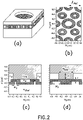
- the device can include a photonic superlattice including a first material, the first material having a first refractive index.
- the first material can include first and second major surfaces and first and second pluralities of features defined though at least one of the first and second major surfaces, the features of the first plurality differing in at least one characteristic from the features of the second plurality.
- the photonic superlattice can support propagation of a first wavelength and a second wavelength approximately at a first angle out of the photonic superlattice, the first and second wavelengths being separated from one another by a first non-propagating wavelength that does not selectively propagate at the first angle out of the photonic superlattice.
- the device further can include a second material having a second refractive index that is different than the first refractive index.
- the second material can be disposed within, between, or over the first and second pluralities of features and can include first and second luminophores.
- the device further can include a first optical component disposed over one of the first and second major surfaces of the first material. The first optical component can receive luminescence emitted by the first luminophore at the first wavelength approximately at the first angle, and can receive luminescence emitted by the second luminophore at the second wavelength approximately at the first angle.
- the photonic superlattice further includes a third material having a third refractive index that is different than the first and second refractive indices.
- the third material can be disposed over at least one of the first and second pluralities of features, and the second material can be disposed over the third material.
- first and second pluralities of features respectively optionally can include first and second pluralities of wells.
- the second material optionally further can include third and fourth luminophores.
- the photonic superlattice further can support propagation of a third wavelength and a fourth wavelength approximately at the first angle out of the photonic superlattice, the third and fourth wavelengths can be separated from one another by a second non-propagating wavelength that does not selectively propagate at the first angle.
- the optical component can receive luminescence emitted by the third luminophore at the third wavelength approximately at the first angle, and can receive luminescence emitted by the fourth luminophore at the fourth wavelength approximately at the first angle.
- the first luminophore is coupled to a first nucleic acid
- the second luminophore is coupled to a second nucleic acid that is different than the first nucleic acid
- the third luminophore is coupled to a third nucleic acid that is different than the first and second nucleic acids
- the fourth luminophore is coupled to a fourth nucleic acid that is different than the first, second, and third nucleic acids.
- the first luminophore optionally is coupled to a first nucleic acid
- the second luminophore optionally is coupled to a second nucleic acid that is different than the first nucleic acid
- the at least one characteristic optionally includes shape, size, or distribution.
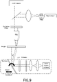
- the device optionally further includes a second optical component configured so as to transmit radiation to the photonic superlattice approximately at a second angle.
- the first luminophore can emit the first wavelength responsive to the radiation transmitted by the second optical component, and the second luminophore can emit the second wavelength responsive to the radiation transmitted by the second optical component.
- the second angle is approximately the same as the first angle.
- the first and second angles optionally each can be approximately normal to the first and second major surfaces.
- the second angle is approximately orthogonal to the first angle.
- the first and second optical components include the same optical component.
- the first optical component is disposed over the first major surface of the first material, and wherein the second optical component is disposed over the second major surface of the first material.
- the device optionally can include a broadband excitation source configured to generate the radiation transmitted to the photonic superlattice by the second optical component.
- the broadband excitation source includes a light emitting diode.
- the device optionally includes at least one microfluidic feature in contact with the photonic superlattice and configured to provide a flow of one or more analytes to the first and second pluralities of features.
- the first optical component optionally includes an image sensor configured to image the received first and second wavelengths.
- the first material optionally can include a polymer or a glass.
- the second material optionally can include a fluid or a gel.
- the first angle optionally is approximately normal to the first and second major surfaces.
- the first luminophore optionally is coupled to a first polynucleotide to be sequenced
- the second luminophore optionally is coupled to a second polynucleotide to be sequenced.
- the first polynucleotide is coupled to a feature of the first plurality of features
- the second polynucleotide is coupled to a feature of the second plurality of features.
- the device optionally further can include a first polymerase adding a first nucleic acid to a third polynucleotide that is complementary to and coupled to the first polynucleotide.
- the first nucleic acid can be coupled to the first luminophore.
- the device optionally further can include a second polymerase adding a second nucleic acid to a fourth polynucleotide that is complementary to and coupled to the second polynucleotide.
- the second nucleic acid can be coupled to the second luminophore.
- the device further can include a channel flowing a first liquid including the first and second nucleic acids and the first and second polymerases into, between, or over the first and second pluralities of features.
- a method for use in luminescent imaging.
- the method can include providing a photonic superlattice including a first material, the first material having a first refractive index.
- the first material can include first and second major surfaces and first and second pluralities of features defined though at least one of the first and second major surfaces.
- the features of the first plurality can differ in at least one characteristic from the features of the second plurality.
- the photonic superlattice can support propagation of a first wavelength and a second wavelength approximately at a first angle out of the photonic superlattice.
- the first and second wavelengths can be separated from one another by a first non-propagating wavelength that does not selectively propagate at the first angle out of the photonic superlattice.
- the method further can include providing a second material having a second refractive index that is different than the first refractive index.
- the second material can be disposed within, between, or over the first and second pluralities of features and can include first and second luminophores.
- the method further can include providing a first optical component disposed over one of the first and second major surfaces of the first material.
- the method further can include receiving by the first optical component luminescence emitted by the first luminophore at the first wavelength approximately at the first angle; and receiving by the first optical component luminescence emitted by the second luminophore at the second wavelength approximately at the first angle.
- the first and second pluralities of features respectively include first and second pluralities of wells.
- the photonic superlattice optionally further includes a third material having a third refractive index that is different than the first and second refractive indices.
- the third material can be disposed over at least one of the first and second pluralities of features, and the second material can be disposed over the third material.
- the second material optionally further can include third and fourth luminophores.
- the photonic superlattice further can support propagation of a third wavelength and a fourth wavelength approximately at the first angle out of the photonic superlattice.
- the third and fourth wavelengths can be different than each of the first and second wavelengths and can be separated from one another by a second non-propagating wavelength that does not selectively propagate at the first angle.
- the method further can include receiving by the first optical component luminescence emitted by the third luminophore at the third wavelength approximately at the first angle; and receiving by the first optical component luminescence emitted by the fourth luminophore at the fourth wavelength approximately at the first angle.
- the first luminophore is coupled to a first nucleic acid
- the second luminophore is coupled to a second nucleic acid that is different than the first nucleic acid
- the third luminophore is coupled to a third nucleic acid that is different than the first and second nucleic acids
- the fourth luminophore is coupled to a fourth nucleic acid that is different than the first, second, and third nucleic acids.
- the first luminophore optionally is coupled to a first nucleic acid
- the second luminophore optionally is coupled to a second nucleic acid that is different than the first nucleic acid
- the at least one characteristic optionally includes shape, size, or distribution.
- the method optionally further can include, by a second optical component, transmitting radiation to the photonic superlattice approximately at a second angle.
- the first luminophore can emit the first wavelength responsive to the radiation transmitted by the second optical component, and the second luminophore can emit the second wavelength responsive to the radiation transmitted by the second optical component.
- the second angle is approximately the same as the first angle.
- the first and second angles each can be approximately normal to the first and second major surfaces.
- the second angle is approximately orthogonal to the first angle.
- the first and second optical components include the same optical component.
- the first optical component is disposed over the first major surface of the first material
- the second optical component is disposed over the second major surface of the first material.
- the method optionally further can include generating by a broadband radiation source the radiation transmitted to the photonic superlattice by the second optical component.
- the broadband excitation source includes a light emitting diode.
- the method optionally further can include flowing one or more analytes into, between, or over the first and second pluralities of features by at least one microfluidic feature in contact with the photonic superlattice.
- the first optical component optionally includes an image sensor imaging the received first and second wavelengths.
- the first material optionally includes a polymer or a glass. Additionally, or alternatively, the second material optionally includes a fluid or a gel.
- the first angle optionally is approximately normal to the first and second major surfaces.
- the method optionally further can include coupling the first luminophore to a first polynucleotide to be sequenced; and coupling the second luminophore to a second polynucleotide to be sequenced.
- the method further can include coupling the first polynucleotide to a feature of the first plurality of features; and coupling the second polynucleotide to a feature of the second plurality of features.
- the method further can include, by a first polymerase, adding a first nucleic acid to a third polynucleotide that is complementary to and coupled to the first polynucleotide.
- the first nucleic acid can be coupled to the first luminophore.
- the method optionally further can include, by a second polymerase, adding a second nucleic acid to a fourth polynucleotide that is complementary to and coupled to the second polynucleotide.
- the second nucleic acid can be coupled to the second luminophore.
- the method optionally further can include flowing a first liquid including the first and second nucleic acids and the first and second polymerases into, between, or over the first and second pluralities of features.
- the method optionally further can include, after receiving by the first optical component the luminescence emitted by the first and second luminophores, respectively decoupling the first and second luminophores from the first and second polynucleotides to be sequenced.
- the method further can include, after respectively decoupling the first and second luminophores from the first and second polynucleotides to be sequenced, flowing a second liquid including third and fourth nucleic acids and third and fourth polymerases into, between, or over the first and second pluralities of features.
- the third nucleic acid can be coupled to the first luminophore
- the fourth nucleic acid can be coupled to the second luminophore.
- the method optionally further can include, by the third polymerase, adding the third nucleic acid or the fourth nucleic acid to the third polynucleotide; or by the fourth polymerase, adding the third nucleic acid or the fourth nucleic acid to the fourth polynucleotide.
- composition can include a photonic superlattice; and a first nucleic acid in contact with the photonic superlattice.
- the photonic superlattice includes a first material having a first refractive index.
- the first material can include first and second major surfaces and first and second pluralities of features defined though at least one of the first and second major surfaces.
- the features of the first plurality can differ in at least one characteristic from the features of the second plurality.
- the photonic superlattice can support propagation of a first wavelength and a second wavelength approximately at a first angle out of the photonic superlattice.
- the first and second wavelengths can be separated from one another by a first non-propagating wavelength that does not selectively propagate at the first angle out of the photonic superlattice.
- the composition further can include a second material having a second refractive index that is different than the first refractive index.
- the second material can be disposed within, between, or over the first and second pluralities of features and can include first and second luminophores.
- the first luminophore can be coupled to the first nucleic acid
- the second luminophore can be coupled to a second nucleic acid that is different than the first nucleic acid.
- the first and second pluralities of features respectively include first and second pluralities of wells.
- the first luminophore can emit luminescence at the first wavelength
- the second luminophore can emit luminescence at the second wavelength.
- the luminescence emitted by the first luminophore approximately is at the first angle
- the luminescence emitted by the second luminophore approximately is at the first angle.
- the first angle is approximately normal to the first and second major surfaces.
- the photonic superlattice optionally further includes a third material having a third refractive index that is different than the first and second refractive indices.
- the third material can be disposed over at least one of the first and second pluralities of features, and the second material can be disposed over the third material.
- the second material optionally further can include third and fourth luminophores.
- the photonic superlattice further can support propagation of a third wavelength and a fourth wavelength approximately at the first angle out of the photonic superlattice, the third and fourth wavelengths can be separated from one another by a second non-propagating wavelength that does not selectively propagate at the first angle.
- the third luminophore can emit luminescence at the third wavelength approximately at the first angle
- the fourth luminophore can emit luminescence at the fourth wavelength approximately at the first angle.
- the first luminophore is coupled to a first nucleic acid
- the second luminophore is coupled to a second nucleic acid that is different than the first nucleic acid
- the third luminophore is coupled to a third nucleic acid that is different than the first and second nucleic acids
- the fourth luminophore is coupled to a fourth nucleic acid that is different than the first, second, and third nucleic acids.
- the first luminophore is coupled to a first nucleic acid
- the second luminophore is coupled to a second nucleic acid that is different than the first nucleic acid.
- the at least one characteristic optionally includes shape, size, or distribution.
- the first luminophore optionally can emit the first wavelength responsive to radiation approximately at a second angle
- the second luminophore can emit the second wavelength responsive to radiation approximately at the second angle.
- the second angle is approximately the same as the first angle.
- the first and second angles optionally each are approximately normal to the first and second major surfaces.
- the second angle is approximately orthogonal to the first angle.
- the first material optionally includes a polymer or a glass. Additionally, or alternatively, the second material optionally includes a fluid or a gel. Additionally, or alternatively, the first luminophore optionally is coupled to a first polynucleotide to be sequenced, and the second luminophore is coupled to a second polynucleotide to be sequenced. Optionally, the first polynucleotide is coupled to a feature of the first plurality of features, and the second polynucleotide is coupled to a feature of the second plurality of features.
- the composition optionally further can include a first polymerase adding a first nucleic acid to a third polynucleotide that is complementary to and coupled to the first polynucleotide.
- the first nucleic acid can be coupled to the first luminophore.
- the composition optionally further can include a second polymerase adding a second nucleic acid to a fourth polynucleotide that is complementary to and coupled to the second polynucleotide.
- the second nucleic acid can be coupled to the second luminophore.
- the composition further can include a channel flowing a first liquid including the first and second nucleic acids and the first and second polymerases into, between, or over the first and second pluralities of features.
- the photonic superlattice further is in contact with a microfluidic feature.
- the microfluidic feature includes a nanowell or a microfluidic channel.
- the composition optionally further can include a luminophore that can emit luminescence at a wavelength.
- the luminescence emitted by the luminophore is at an angle to the first and second major surfaces.
- the angle is approximately normal to the first and second major surfaces.
- the photonic superlattice optionally includes a first material having a first refractive index.
- the first material can include first and second major surfaces and a plurality of features defined through at least one of the first and second major surfaces.
- the composition further can include a second material having a second refractive index that is different than the first refractive index; and a third material having a third refractive index that is different than the first and second refractive indices.
- the third material can be disposed over at least some features of the plurality of features, and the second material can be disposed over the third material.
- the first material includes a polymer or a glass.
- the second material optionally includes a fluid or a gel.
- the photonic superlattice optionally can support propagation of a first wavelength and a second wavelength approximately at a first angle out of the photonic superlattice.
- the first and second wavelengths can be separated from one another by a first non-propagating wavelength that does not selectively propagate at the first angle out of the photonic superlattice.
- the photonic superlattice further can support propagation of a third wavelength and a fourth wavelength approximately at the first angle out of the photonic superlattice.
- the third and fourth wavelengths can be separated from one another by a second non-propagating wavelength that does not selectively propagate at the first angle the photonic superlattice.
- the composition optionally further can include a luminophore coupled to the nucleic acid.
- the luminophore can emit luminescence at an angle and at a wavelength responsive to radiation approximately at the angle.
- the nucleic acid optionally is coupled to a first polynucleotide to be sequenced.
- the first polynucleotide is coupled to a feature of the photonic superlattice.
- the composition optionally further can include a polymerase adding the nucleic acid to a second polynucleotide that is complementary to and coupled to the first polynucleotide.
- composition can include a photonic superlattice; and a microfluidic feature in contact with the photonic superlattice.
- the microfluidic feature includes a nanowell or a microfluidic channel.
- the photonic superlattice optionally includes a first material having a first refractive index.
- the first material can include first and second major surfaces and first and second pluralities of features defined though at least one of the first and second major surfaces.
- the features of the first plurality can differ in at least one characteristic from the features of the second plurality.
- the photonic superlattice can support propagation of a first wavelength and a second wavelength approximately at a first angle out of the photonic superlattice.
- the first and second wavelengths can be separated from one another by a first non-propagating wavelength that does not selectively propagate at the first angle out of the photonic superlattice.
- the composition further can include a second material having a second refractive index that is different than the first refractive index.
- the second material can be disposed within, between, or over the first and second pluralities of features and can include first and second luminophores.
- the first luminophore can be coupled to the first nucleic acid
- the second luminophore can be coupled to a second nucleic acid that is different than the first nucleic acid.
- the first and second pluralities of features respectively include first and second pluralities of wells.
- the first luminophore optionally can emit luminescence at the first wavelength
- the second luminophore optionally can emit luminescence at the second wavelength.
- the luminescence emitted by the first luminophore is approximately at the first angle
- the luminescence emitted by the second luminophore is approximately at the first angle.
- the first angle is approximately normal to the first and second major surfaces.
- the photonic superlattice optionally further includes a third material having a third refractive index that is different than the first and second refractive indices.
- the third material can be disposed over at least one of the first and second pluralities of features, and the second material can be disposed over the third material.
- the second material optionally further can include third and fourth luminophores.
- the photonic superlattice further can support propagation of a third wavelength and a fourth wavelength approximately at the first angle out of the photonic superlattice.
- the third and fourth wavelengths can be separated from one another by a second non-propagating wavelength that does not selectively propagate at the first angle out of the photonic superlattice.
- the third luminophore can emit luminescence at the third wavelength approximately at the first angle
- the fourth luminophore can emit luminescence at the fourth wavelength approximately at the first angle.
- the first luminophore is coupled to a first nucleic acid
- the second luminophore is coupled to a second nucleic acid that is different than the first nucleic acid
- the third luminophore is coupled to a third nucleic acid that is different than the first and second nucleic acids
- the fourth luminophore is coupled to a fourth nucleic acid that is different than the first, second, and third nucleic acids.
- the first luminophore optionally is coupled to a first nucleic acid
- the second luminophore optionally is coupled to a second nucleic acid that is different than the first nucleic acid
- the at least one characteristic optionally includes shape, size, or distribution.
- the first luminophore optionally can emit the first wavelength responsive to radiation approximately at a second angle
- the second luminophore optionally can emit the second wavelength responsive to radiation approximately at the second angle
- the second angle is approximately the same as the first angle.
- the first and second angles optionally each are approximately normal to the first and second major surfaces.
- the second angle is approximately orthogonal to the first angle.
- the first material optionally includes a polymer or a glass. Additionally, or alternatively, the second material optionally includes a fluid or a gel.
- the first luminophore is coupled to a first polynucleotide to be sequenced
- the second luminophore is coupled to a second polynucleotide to be sequenced.
- the first polynucleotide is coupled to a feature of the first plurality of features
- the second polynucleotide is coupled to a feature of the second plurality of features.
- the composition optionally further can include a first polymerase adding a first nucleic acid to a third polynucleotide that is complementary to and coupled to the first polynucleotide.
- the first nucleic acid can be coupled to the first luminophore.
- the composition further can include a second polymerase adding a second nucleic acid to a fourth polynucleotide that is complementary to and coupled to the second polynucleotide.
- the second nucleic acid can be coupled to the second luminophore.
- the composition further can include a channel flowing a first liquid including the first and second nucleic acids and the first and second polymerases into, between, or over the first and second pluralities of features.
- the composition further can include a luminophore that can emit luminescence at a wavelength.
- the luminescence emitted by the luminophore is at an angle to the first and second major surfaces.
- the angle is approximately normal to the first and second major surfaces.
- the photonic superlattice optionally includes a first material having a first refractive index.
- the first material can include first and second major surfaces and a plurality of features defined through at least one of the first and second major surfaces.
- the composition further can include a second material having a second refractive index that is different than the first refractive index; and a third material having a third refractive index that is different than the first and second refractive indices.
- the third material can be disposed over the plurality of features, and the second material can be disposed over the third material.
- the first material includes a polymer or a glass.
- the second material optionally includes a fluid or a gel.
- the photonic superlattice optionally can support propagation of a first wavelength and a second wavelength approximately at an angle out of the photonic superlattice.
- the first and second wavelengths can be separated from one another by a first non-propagating wavelength that does not selectively propagate at the angle out of the photonic superlattice.
- the photonic superlattice further can support propagation of a third wavelength and a fourth wavelength approximately at the angle out of the photonic superlattice.
- the third and fourth wavelengths can be separated from one another by a second non-propagating wavelength that does not selectively propagate at the angle out of the photonic superlattice.
- the composition optionally further can include a luminophore coupled to the nucleic acid.
- the luminophore can emit luminescence at a first angle and at a wavelength responsive to radiation approximately at a second angle.
- the nucleic acid optionally is coupled to a first polynucleotide to be sequenced.
- the first polynucleotide is coupled to a feature of the photonic superlattice.
- the composition optionally further can include a polymerase adding the nucleic acid to a second polynucleotide that is complementary to and coupled to the first polynucleotide.
- a composition can include a photonic superlattice; and a pattern of analyte sites in contact with the photonic superlattice.
- a first luminophore can be present at a first subset of analyte sites in the pattern and a second luminophore can be present at a second subset of analyte sites in the pattern.
- the photonic superlattice is tuned to selectively propagate into the photonic superlattice a first wavelength that excites the first luminophore and a second wavelength that excites the second luminophore.
- the first and second wavelengths are separated by a non-propagating wavelength that does not selectively propagate into the photonic superlattice.
- the photonic superlattice is tuned to create field enhancements for the first and second wavelengths at the analyte sites.
- a third luminophore optionally is present at a third subset of analyte sites in the pattern.
- the photonic superlattice can be further tuned to selectively propagate into the photonic superlattice a third wavelength that excites the third luminophore.
- a fourth luminophore is present at a fourth subset of analyte sites in the pattern.
- the photonic superlattice can be further tuned to selectively propagate into the photonic superlattice a fourth wavelength that excites the fourth luminophore.
- the first, second, third and fourth wavelengths are separated by respective wavelengths that do not selectively propagate into the photonic superlattice.
- the analyte optionally includes nucleic acid.
- a method can include providing a device including a photonic superlattice; and a pattern of analyte sites in contact with the photonic superlattice.
- a first luminophore can be present at a first subset of analyte sites in the pattern and a second luminophore is present at a second subset of analyte sites in the pattern.
- the method also can include contacting the device with radiation that includes a first wavelength and a second wavelength.
- the photonic superlattice selectively propagates into the photonic superlattice the first wavelength to excite the first luminophore and selectively propagates into the photonic superlattice the second wavelength to excite the second luminophore.
- the first and second wavelengths can be separated by a non-propagating wavelength that does not selectively propagate into the photonic superlattice.
- the method further can include detecting emission from the first and second luminophores, thereby detecting the first and second analytes.
- the superlattice is tuned to create field enhancements for the first and second wavelengths at the analyte sites.
- a third luminophore optionally is present at a third subset of analyte sites in the pattern.
- the photonic superlattice can be further tuned to selectively propagate into the photonic superlattice a third wavelength that excites the third luminophore.
- a fourth luminophore is present at a fourth subset of analyte sites in the pattern.
- the photonic superlattice can be further tuned to selectively propagate into the photonic superlattice a fourth wavelength that excites the fourth luminophore.
- the first, second, third and fourth wavelengths are separated by respective wavelengths that do not selectively propagate into the photonic superlattice.
- the analyte optionally includes nucleic acid.
- Embodiments of the present invention provide photonic superlattice-based devices and compositions for use in luminescent imaging, and methods of using the same.
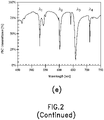
- the term "photonic superlattice” means a periodic structure, including one or more optically transparent materials, that selectively affects the propagation of radiation at first and second wavelengths compared to radiation at a third wavelength, wherein the third wavelength occurs between the first and second wavelengths in the electromagnetic spectrum.
- the structure can selectively propagate radiation at the first and second wavelengths through the structure or at an angle out of the structure.
- the structure can selectively inhibit propagation of radiation at the first and second wavelengths through the structure or at an angle out of the structure.
- the structure can selectively propagate radiation at the third wavelength through the structure or at an angle out of the structure.
- the structure can selectively inhibit propagation of radiation at the third wavelength through the structure or at an angle out of the structure.
- the material(s) can include features that are distributed in one or more dimensions, e.g., in one dimension, in two dimensions, or in three dimensions.
- the shape, size, and distribution of the features, as well as the refractive index of the material(s), can be tuned so as select the particular wavelengths that can propagate through or at an angle out of the photonic superlattice, and so as to select the particular wavelengths that do not propagate substantially through or at an angle out of the photonic superlattice.
- a photonic superlattice can include a material that extends in three dimensions, e.g., has a length, a width, and a thickness.
- the material can have two major surfaces that each lie within a plane defined by the length and the width, and separated from one another by the thickness.
- the material can be patterned in two or more dimensions so as to define a photonic band structure that permits propagation of at least first and second wavelengths within, or at an angle out of, the plane defined by the length and the width, and that inhibits propagation of at least a third wavelength that separates the first and second wavelengths within, or at an angle out of, the material.
- the pattern can include, for example, a plurality of features such as wells or posts that are defined within the material, e.g., through one or both of the major surfaces of the material, the material being absent within or between the features, such as within the wells or between the posts.
- a space within or between the features can be filled with one or more additional materials that respectively can have different refractive indices than that of the material and than that of one another.
- the particular wavelengths that propagate or do not propagate through, or at an angle out of, the photonic superlattice can be based on the refractive indices of the material and of any additional materials disposed within the features or between the features, as well as based on the characteristics of the features, such as the shape, size, and distribution of the features.
- the features need not all be the same as one another. For example, some of the features can differ in at least one characteristic from others of the features.
- One or more of the materials of the photonic superlattice can be or include a "dielectric material,” meaning a fluidic, solid, or semi-solid material that is optically transparent and is an electrical insulator.
- fluidic dielectric materials include gases such as air, nitrogen, and argon, as well as liquids such as water, aqueous solvents, and organic solvents.
- solid dielectric materials include glasses (e.g., inorganic glasses such as silica, or modified or functionalized glasses) and polymers (such as acrylics, polystyrene, copolymers of styrene and other materials, polypropylene, polyethylene, polybutene, polyurethanes, TEFLON TM , cyclic olefins, polyimides, or nylon).
- glasses e.g., inorganic glasses such as silica, or modified or functionalized glasses
- polymers such as acrylics, polystyrene, copolymers of styrene and other materials, polypropylene, polyethylene, polybutene, polyurethanes, TEFLON TM , cyclic olefins, polyimides, or nylon.
- semi-solid dielectric materials include gels, such as hydrogels.
- one or more materials of the photonic superlattice can be or include a solid semiconductor material that is optically transparent.
- gel is intended to mean a semi-solid or semi-rigid material that is permeable to liquids and gases.
- gel material can swell when liquid is taken up and can contract when liquid is removed by drying.
- Exemplary gels can include, but are not limited to, those having a colloidal structure, such as agarose or a hydrogel; polymer mesh structure, such as gelatin; or cross-linked polymer structure, such as polyacrylamide, SFA (see, for example, US 2011/0059865 , the entire contents of which are incorporated by reference herein) or PAZAM (see, for example, US 2014/0079923 , the entire contents of which are incorporated by reference herein).
- Particularly useful gel material will conform to the shape of a well or other concave feature where it resides.
- the term "well” means a discrete concave feature in a material having a surface opening (aperture) that is completely surrounded by interstitial region(s) of the surface.
- a well can have characteristics such as size (e.g., volume, diameter, and depth), shape (e.g., round, elliptical, triangular, square, polygonal, star shaped (having any suitable number of vertices), irregular, or having concentric wells separated by a dielectric material), and distribution (e.g., spatial locations of the wells within the dielectric material, e.g., regularly spaced or periodic locations, or irregularly spaced or aperiodic locations).
- the cross section of a well can be, but need not necessarily be, uniform along the length of the well.
- post means a discrete convex feature protruding from the surface of a material and that is completely surrounded by interstitial region(s) of the surface.
- a post can have characteristics such as size (e.g., volume, diameter, and depth), shape (e.g., round, elliptical, triangular, square, polygonal, star shaped (having any suitable number of vertices), irregular, or having concentric posts separated by a dielectric material), and distribution (e.g., spatial locations of the posts protruding from the surface of the dielectric material, e.g., regularly spaced or periodic locations, or irregularly spaced or aperiodic locations).
- the cross section of a post can be, but need not necessarily be, uniform along the length of the post.
- surface means a part or layer of a material that is in contact with another material.
- an interstitial region is intended to mean an area in a material or on a surface that separates areas of the material or surface.
- an interstitial region can separate one feature of a photonic superlattice from another feature of a photonic superlattice, or an interstitial region can separate one site of an array from another site of the array.
- the term “luminescent” means emitting cold body radiation
- the term “luminophore” means an item that is luminescent.
- the term “luminescent” is intended to be distinct from incandescence which is radiation emitted from a material as a result of heat. Generally luminescence results when an energy source displaces an electron of an atom out of its lowest energy ground state into a higher energy excited state; then the electron returns the energy in the form of radiation so it can fall back to its ground state.
- a particularly useful type of luminescent item is one that emits cold body radiation when energy is provided by excitation radiation.
- photoluminescent items include “fluorescent” items that emit cold body radiation relatively quickly (e.g., less than a millisecond) after excitation radiation, and “phosphorescent” items that emit cold body radiation relatively slowly (e.g., greater than or equal to a millisecond) after excitation radiation.
- Photoluminescence can be perceived as emission of radiation by an item at a wavelength that is a result of irradiating the item at another wavelength.
- Another useful type of luminescent item is one that emits cold body radiation when energy is provided by a chemical or biological reaction. Such items can be referred to as "chemiluminescent.”
- any of a variety of signals can be detected in a method set forth herein including, for example, an optical signal such as absorbance of radiation, luminescence emission, luminescence lifetime, luminescence polarization, or the like; Rayleigh and/or Mie scattering; or the like.
- Exemplary labels that can be detected in a method set forth herein include, without limitation, a fluorophore, luminophore, chromophore, nanoparticle (e.g., gold, silver, carbon nanotubes), or the like.
- feature means a distinctive and repeated variation in the structure or composition of a material such as a solid support.
- a collection of the features can form an array or lattice in or on the material.
- Exemplary features include, but are not limited to wells, posts, ridges, channels, sites bearing analytes, layers of a multilayer material, areas in or on a material having a chemical composition that differ from the chemical composition of other areas in or on the material and the like.
- a feature can have characteristics such as size (e.g., volume, diameter, and depth), shape (e.g., round, elliptical, triangular, square, polygonal, star shaped (having any suitable number of vertices), irregular, or having concentric features separated by a dielectric material), and distribution (e.g., spatial locations of the features within or on the dielectric material, e.g., regularly spaced or periodic locations, or irregularly spaced or aperiodic locations).
- the cross section of a feature can be, but need not necessarily be, uniform along the length of the feature.
- site means a location in an array for a particular species of molecule or cell (or other analyte).
- a site can contain only a single molecule (or cell or other analyte) or it can contain a population of several molecules (or cells or analytes) of the same species.
- sites are present on a material prior to attaching a particular analyte.
- the site is created by attachment of a molecule or cell (or other analyte) to the material.
- Sites of an array are typically discrete. The discrete sites can be contiguous or they can have spaces between each other. It will be understood that a site is a type of feature.
- a site can function as a component of a lattice, array or both.
- array means a population of sites that can be differentiated from each other according to relative location.
- the term "pitch,” when used in reference to features of a lattice (e.g. photonic superlattice) or array, is intended to refer to the center-to-center spacing for adjacent features of the lattice or array.
- a pattern of features can be characterized in terms of average pitch. The pattern can be ordered such that the coefficient of variation around the average pitch is small, or the pattern can be random in which case the coefficient of variation can be relatively large.
- the average pitch can be, for example, at least about on the order of the wavelength of light in the material. For example, average pitch can be in the range of a few nanometers to a micrometer.
- the pitch is at most 1 micrometer, 800 nm, 600 nm, 500 nm, 400 nm, 200 nm, 100 nm or smaller.
- the pitch can be at least 100 nm, 200 nm, 400 nm, 500 nm, 600 nm, 800 nm, 1 micrometer or larger.
- different types of features can have different pitches and patterns than one another.
- the pitch for the features of one type e.g. in a first lattice
- can differ from the pitch for features of another type e.g. in a second lattice).
- the term "random" can be used to refer to the spatial distribution, e.g., arrangement, of locations on a surface.
- one or more features of a photonic superlattice e.g., wells or posts
- nearest neighbor features which can be of the same type or different type than one another, have variable spacing between each other.
- the spacing between features of the same type or a different type than one another can be ordered, for example, forming a regular pattern such as a rectilinear grid or a hexagonal grid.
- the present photonic superlattices can be ordered in one respect and random in another.
- nucleotide or “nucleic acid” is intended to mean a molecule that includes a sugar and at least one phosphate group, and optionally also includes a nucleobase.
- a nucleotide that lacks a nucleobase can be referred to as "abasic.”
- Nucleotides include deoxyribonucleotides, modified deoxyribonucleotides, ribonucleotides, modified ribonucleotides, peptide nucleotides, modified peptide nucleotides, modified phosphate sugar backbone nucleotides, and mixtures thereof.
- nucleotides examples include adenosine monophosphate (AMP), adenosine diphosphate (ADP), adenosine triphosphate (ATP), thymidine monophosphate (TMP), thymidine diphosphate (TDP), thymidine triphosphate (TTP), cytidine monophosphate (CMP), cytidine diphosphate (CDP), cytidine triphosphate (CTP), guanosine monophosphate (GMP), guanosine diphosphate (GDP), guanosine triphosphate (GTP), uridine monophosphate (UMP), uridine diphosphate (UDP), uridine triphosphate (UTP), deoxyadenosine monophosphate (dAMP), deoxyadenosine diphosphate (dADP), deoxyadenosine triphosphate (dATP), deoxythymidine monophosphate (dTMP), deoxythymidine diphosphate (dTDP), deoxy
- nucleotide or “nucleic acid” also is intended to encompass any nucleotide analogue which is a type of nucleotide that includes a modified nucleobase, sugar and/or phosphate moiety.
- modified nucleobases that can be included in a polynucleotide, whether having a native backbone or analogue structure, include, inosine, xathanine, hypoxathanine, isocytosine, isoguanine, 2-aminopurine, 5-methylcytosine, 5-hydroxymethyl cytosine, 2-aminoadenine, 6-methyl adenine, 6-methyl guanine, 2-propyl guanine, 2-propyl adenine, 2-thioLiracil, 2-thiothymine, 2-thiocytosine, 15 -halouracil, 15-halocytosine, 5-propynyl uracil, 5-propynyl cytosine, 6-azo ura
- polynucleotide refers to a molecule that includes a sequence of nucleotides that are bonded to one another.
- examples of polynucleotides include deoxyribonucleic acid (DNA), ribonucleic acid (RNA), and analogues thereof.
- a polynucleotide can be a single stranded sequence of nucleotides, such as RNA or single stranded DNA, a double stranded sequence of nucleotides, such as double stranded DNA, or can include a mixture of a single stranded and double stranded sequences of nucleotides.
- Double stranded DNA includes genomic DNA, and PCR and amplification products. Single stranded DNA (ssDNA) can be converted to dsDNA and vice-versa. The precise sequence of nucleotides in a polynucleotide can be known or unknown.
- polynucleotides a gene or gene fragment (for example, a probe, primer, expressed sequence tag (EST) or serial analysis of gene expression (SAGE) tag), genomic DNA, genomic DNA fragment, exon, intron, messenger RNA (mRNA), transfer RNA, ribosomal RNA, ribozyme, cDNA, recombinant polynucleotide, synthetic polynucleotide, branched polynucleotide, plasmid, vector, isolated DNA of any sequence, isolated RNA of any sequence, nucleic acid probe, primer or amplified copy of any of the foregoing.
- a gene or gene fragment for example, a probe, primer, expressed sequence tag (EST) or serial analysis of gene expression (SAGE) tag
- genomic DNA genomic DNA fragment, genomic DNA fragment, exon, intron, messenger RNA (mRNA), transfer RNA, ribosomal RNA, ribozyme, cDNA, recombinant polynucleotide, synthetic polynu
- “chemically coupled” is intended to mean an attachment between a first member and a second member.
- such an attachment is normally irreversible under the conditions in which the attached members are used.
- such an attachment is reversible but persists for at least the period of time in which it is used for detecting a subunit of a polymer.
- Such attachment can be formed via a chemical bond, e.g., via a covalent bond, hydrogen bond, ionic bond, dipole-dipole bond, London dispersion forces, or any suitable combination thereof.
- Covalent bonds are only one example of an attachment that suitably can be used to couple a first member to a second member.
- an attachment can be formed by hybridizing a first polynucleotide to a second polynucleotide that inhibits detachment of the first polynucleotide from the second polynucleotide.
- an attachment can be formed using physical or biological interactions, e.g., an interaction between a first protein and a second protein that inhibits detachment of the first protein from the second protein.
- a "polymerase” is intended to mean an enzyme having an active site that assembles polynucleotides by polymerizing nucleotides into polynucleotides.
- a polymerase can bind a primed single stranded polynucleotide template, and can sequentially add nucleotides to the growing primer to form a polynucleotide having a sequence that is complementary to that of the template.
- compositions and devices that include photonic crystal superlattices, such as for multicolor fluorescence signal enhancement from analytes (e.g. DNA clusters) in multiple excitation and/or luminescence emission bands at normal incidence of excitation.
- the superlattices are compatible with previously known epifluorescence microscopy and microscope scanning systems (such as those in commercially available sequencing platforms such as produced by Illumina, Inc. (San Diego, California)) that, in some circumstances, can use multiple fluorescent dyes excited at normal and imaged at normal incidence in various spectral windows.
- the present photonic superlattice-based devices, compositions, and methods suitably can be used in any type of luminescent imaging or any other suitable application, and are not limited to use in sequencing polynucleotides such as DNA.
- Patterning of dielectric substrates previously has been employed successfully to control the size and uniformity of polynucleotide clusters, and to increase the density of such clusters so as to improve throughput of sequencing. See for example, US Pat. App. Publ. No. 2014/0243224 A1 , which is incorporated herein by reference.
- reduction in cluster size has resulted in a considerable reduction in the amount of collected multicolor fluorescence signal.
- detection of weak multicolor fluorescence signals from large sampling areas can become increasingly difficult as the number of labeled nucleotides in DNA clusters is reduced (e.g., down to single-molecule levels or the resolution limits of the imaging system).
- Significant fluorescence signal enhancement therefore can be helpful to facilitate nucleotide identification and increase the throughput of next generation SBS systems.
- periodic patterning of materials in the proximity of fluorescently marked biomolecules can enhance fluorescence signal by creating one- or two-dimensional waveguides with a periodic variation of the refractive index in on the order of wavelength of light.
- waveguides which can be referred to as photonic crystals (PhCs), photonic lattices, photonic crystal lattices, or PhC lattices, can support high-Q resonant modes that can boost fluorescent signals by resonantly enhancing fluorophore excitation, fluorescence collection, or both.
- PhC lattices also can be used in multicolor fluorescence signal enhancement.
- dual-excitation fluorescence signal boost has been achieved with PhCs by resonant enhancement of excitation at different wavelengths that requires adjustment of the angle of incidence of excitation source to match the resonances supported by the PhC.
- U.S. Patent No. 8,344,333 to Lu et al. the entire contents of which are incorporated by reference herein.
- PhC lattices hexagonal, square or honeycomb
- PhC lattices may not provide sufficient parameter space to align multiple resonances with the absorption and/or emission peaks of several SBS dyes.
- photonic superlattices (which also can be referred to as superlattices, photonic crystal superlattices, or PhC superlattices) can be used for multi-wavelength operation at a fixed angle of incidence for any desired number of wavelengths of interest, as they can provide multi-wavelength resonance tuning by breaking modal degeneracies that are present in PhC lattices, and by providing additional Bragg planes for resonant feedback.
- simple photonic lattices including a low-loss dielectric material having a regular array of wells or depressions defined therein, can be highly symmetric and therefore can support only one or a few resonances in the visible band, where absorption and emission peaks of dyes used in fluorescence microscopy can be localized.
- the structural simplicity of such photonic lattices also can provide limited resonance tuning capabilities.
- increasing the complexity of the photonic lattice so as to provide a photonic superlattice e.g., by breaking the underlying lattice periodicity can increase the number of resonances and can increase the parameter space for spectral tuning of individual resonances so as respectively to overlap with excitation wavelengths used to excite luminophores disposed within or above the photonic superlattice or so as to overlap with emission wavelengths of such luminophores disposed within or above the photonic lattice, or both, which excitation wavelengths or emission wavelengths, or both, can be at substantially the same angle as one another.
- FIG. 1 Some exemplary differences between simple PhC lattices and PhC superlattices are shown schematically in FIG. 1 . More specifically, FIG. 1 (a) schematically illustrates plan views of square and hexagonal lattice photonic crystals (PhCs), (b) schematically illustrates plan views of exemplary compositions including PhC superlattices provided herein, (c) schematically illustrates a plot of a simulated transmission spectrum at normal incidence showing resonances of an exemplary PhC lattice, and (d) schematically illustrates a plot of a simulated transmission spectrum at normal incidence showing resonances of an exemplary composition including a PhC superlattice provided herein.
- n 1(a) include a first material having a refractive index of n 1 , and regular patterns of uniformly shaped and sized wells that are defined within the first material and are filled with a second material having a refractive index of n 2 , where n 1 and n 2 are different than each other.
- first and second pluralities of features e.g., wells
- first and second pluralities of features e.g., wells
- n 1 and n 2 are different than each other
- the first and second pluralities of features, e.g., wells differ in at least one characteristic from one another.
- FIG. 1(b) it can be seen that some features, e.g., wells, within a given PhC superlattice can have a different size, shape, or distribution than other features, e.g., wells, within that superlattice.
- the first material can include first and second major surfaces (e.g., surfaces parallel to the plane shown in FIG. 1(b) ), and the features, e.g., wells, can be defined through at least one of the first and second major surfaces.
- the second material which can be disposed within, between, or over the features, e.g., wells, defined through the first and major surfaces of the first material, can include any suitable number of luminophores, e.g., one or more, two or more, three or more, four or more, or five or more luminophores, the luminescence of which can be enhanced by the spectral resonances of the PhC superlattice.
- PhC superlattices such as illustrated in FIG. 1(b) can selectively support propagation of any suitable number of wavelengths at a desired angle out of the photonic superlattice.
- the present PhC superlattices can selectively support propagation of at least first and second wavelengths at about the same angle as one another out of the PhC superlattice, e.g., in a direction approximately normal to the first and second major surfaces of the first material, or any other suitable angle between about 0 degrees and about 90 degrees, inclusive, e.g., an angle between about 15 degrees and about 90 degrees, or between about 30 degrees and about 90 degrees, or between about 45 degrees and about 90 degrees, or between about 60 degrees and about 90 degrees, or between about 75 degrees and about 90 degrees, or between about 85 degrees and about 90 degrees.
- the wavelengths for which the photonic superlattice selectively supports propagation out of the superlattice at the desired angle can be separated from one another by a third wavelength that does not propagate substantially at that angle out of the photonic superlattice.
- simple PhC lattices such as illustrated in FIG. 1(a) can include a relatively low number of resonances, e.g., one or two resonances, such as indicated by the significantly reduced emission at about 520 nm and 640 nm.
- present compositions including PhC superlattices such as illustrated in FIG. 1(b) can have numerous resonances, e.g., three or more, four or more, five or more, six or more, seven or more, or eight or more resonances, such as indicated by the multiple regions of significantly reduced emission at about 520 nm, 570 nm, 640 nm, and 700 nm in FIG. 1(d) .
- Each of such resonances can correspond to a wavelength for which the PhC superlattice selectively supports propagation out of the superlattice at or about the desired angle, and the high-transmittance regions between such resonances can correspond to non-propagating wavelengths that do not propagate substantially at the desired angle out of the superlattice.
- the resonances respectively can correspond to excitation wavelengths of luminophores within the second material disposed within, between, or over the features of the photonic superlattice, or to emission wavelengths of such luminophores, or any suitable combination of excitation and emission wavelengths.
- the excitation wavelengths all can be about at the same angle as one another, or the emission wavelengths all can be about at the same angle as one another, or both.
- the luminophores are disposed within or between features of the photonic superlattice, the luminophores can be excited directly by the excitation wavelengths. In some embodiments in which the luminophores are disposed over the features of the photonic superlattice, the luminophores can be disposed in the near field of the photonic superlattice and excited evanescently by the excitation wavelengths.
- Superlattice design parameters can be computationally adjusted so as to tune resonances to desired excitation or emission peaks of luminophores within the second material disposed within, between, or over the features of the photonic superlattice, for example using one or more of Finite-Difference Time-Domain (FDTD), Rigorous Coupled-Wave Analysis (RCWA), and Plane-Wave Expansion (PWE).
- FDTD Finite-Difference Time-Domain
- RCWA Rigorous Coupled-Wave Analysis
- PWE Plane-Wave Expansion
- Design optimization can employ multi-parameter sweeps or self-optimization algorithms to maximize luminescence signal, e.g., fluorescence signal, in desired spectral regions.
- the refractive indices of material(s) that a photonic superlattice is to include, and the wavelengths for which it is desired that the photonic superlattice selectively support propagation at an angle out of the superlattice can be computationally defined, and any suitable combination of FDTD, RCWA, PWE, or any other suitable optimization program(s) can be used so as to adjust other parameters of the superlattice, such as the size, shape, and distribution of different feature types within the superlattice, so as to explore the design parameter space of the superlattice and to identify combinations of parameters that align the spectral features of the superlattice with the desired luminophore excitation or emission wavelengths.
- the PhC superlattice can include any suitable number of differently shaped, sized, or distributed features, e.g., can include two or more pluralities of features that differ from one another in at least one characteristic, three or more pluralities of features that differ from one another in at least one characteristic, four or more pluralities of features that differ from one another in at least one characteristic, five or more pluralities of features that differ from one another in at least one characteristic, or ten or more pluralities of features that differ from one another in at least one characteristic.
- the features can be, but need not necessarily be, all of the same type as one another.
- one or more features can include a well, and one or more features can include a post.
- the present compositions can include any suitable number of materials, and are not limited to including only two materials.
- the present photonic superlattices optionally can include at least a third material having a refractive index that is different than the refractive indices of the first and second materials.
- the third material can be disposed over some or all of the features, e.g., over at least one of the first and second pluralities of features, and the second material can be disposed over the third material.
- the third material also can be disposed over at least one of the first and second major surfaces of the first material.
- the third material can have a higher refractive index than those of the first and second materials, and can act as a cladding so as to increase containment of light of desired wavelengths or angles within the photonic superlattice.
- a fourth material which can have a different refractive index than the first, second, and optional third materials (e.g., can be a polymer or a glass), can be disposed within or between some or all of the features.
- the present superlattices can be in optical contact with one or more nucleic acids, or can be in optical contact with one or more microfluidic features, or can be in optical contact with one or more nucleic acids and one or more microfluidic features.
- one or more nucleic acids such as polynucleotide clusters with luminophore-labeled nucleotides, such as DNA clusters with fluorescently-labeled nucleotides
- the PhC superlattice surface e.g., disposed within the second material within, between, or over the features of the superlattice
- FIG. 2 (a) schematically illustrates a perspective view of an exemplary composition including a 2D PhC superlattice in contact with an integrated microfluidic reaction chamber provided herein, (b) schematically illustrates a plan view of the composition of FIG. 2(a), (c) schematically illustrates a first cross-sectional view of the composition of FIG. 2(a), (d) schematically illustrates a second cross-sectional view of the composition of FIG. 2(a) , and (e) schematically illustrates a plot of a simulated transmission spectrum at normal incidence showing resonances of the exemplary composition of FIGS. 2(a)-2(d) provided herein.
- a photonic superlattice includes a first material ( n 1 or n clad ) having at least first and second pluralities of features, e.g., wells, defined through a first major surface thereof, and an optional third material ( n 3 or n PhC ) disposed over the features and the first major surface of the first material.
- a second material ( n 2 or n Fill , n 1 ⁇ n 2 ⁇ n 3 ) is disposed within, between, or over the features, e.g., over the optional third material, in a manner similar to that described above with reference to FIGS. 1(a)-(d) .
- the first and second pluralities of features of the photonic superlattice can differ from one another in at least one characteristic, such as shape, size, or distribution.
- the present photonic superlattices optionally can be in fluidic contact with a microfluidic feature, such as a nanowell or a microfluidic channel, e.g. in a manner such as described herein with reference to FIGS. 2(a)-(d) .
- a fourth material n 4 , n 1 ⁇ n 2 ⁇ n 3 ⁇ n 4
- optionally optionally can be disposed over the third material so as to define one or more fluidic features that are disposed over the photonic crystal and within which the second material can be disposed, such as in the non-limiting example illustrated in FIGS.
- the present photonic superlattices optionally can be in contact with at least one nucleic acid, e.g. in a manner such as described herein with reference to FIGS. 2(a)-(d) .
- the composition optionally can include at least one luminophore capable of emitting luminescence at a particular wavelength.
- the luminescence can be collected at an angle to the first and second major surfaces of the first material, e.g., approximately normal to the first and second major surfaces.
- the second material can include at least first and second luminophores.
- the photonic superlattice can selectively support propagation of first and second wavelengths approximately at a defined angle out of the photonic superlattice, the first and second wavelengths being separated from one another by a third wavelength that does not selectively propagate at that defined angle out of the photonic superlattice.
- the photonic superlattice can inhibit propagation of first and second wavelengths approximately at a defined angle into the photonic superlattice, the first and second wavelengths being separated from one another by a third wavelength that can propagate into the photonic superlattice.
- the luminescence from the first and second luminophores i.e., at the first and second wavelengths
- the first luminophore can emit luminescence at the first wavelength
- the second luminophore can emit luminescence at the second wavelength.
- the first luminophore can emit the first wavelength responsive to irradiation at a third wavelength
- the second luminophore can emit the second wavelength responsive to irradiation at a fourth wavelength, wherein the first, second, third, and fourth wavelengths all can be different than one another.
- the photonic superlattice can support transmission of the third and fourth (excitation) wavelengths into the photonic superlattice in such a manner that the third and fourth wavelengths can excite the first and second luminophores, resulting in the first and second luminophores respectively emitting the first and second wavelengths out of the photonic superlattice at the defined angle.
- the photonic superlattice can be irradiated with the third and fourth wavelengths at an angle that can be substantially the same as the angle which the first and second wavelengths propagate out of the photonic superlattice, e.g., in a direction approximately normal to the first and second major surfaces, or can be at a different angle than that at which the first and second wavelengths propagate out of the photonic superlattice, e.g., in a direction approximately orthogonal to the first angle.
- one or both of the first and second luminophores need not be excited by radiation in order to luminesce, but instead can luminesce responsive to another suitable stimulus, such as a chemical or biological reaction.
- the second luminophores can chemiluminesce.
- the second material optionally can include any suitable number of luminophores, such as at least third and fourth luminophores, and the photonic superlattice can further support propagation of wavelengths respectively emitted from such luminophores, selectively, at about the defined angle out of the photonic superlattice. Such wavelengths can be separated from one another by wavelengths that are not selectively emitted at the defined angle out of the photonic superlattice.
- resonance wavelengths of a photonic superlattice can be determined at least in part by the refractive indices of the (optionally) dielectric materials included within the photonic superlattice, such as n Clad corresponding to the refractive index of the first material of the photonic superlattice (also referred to as n 1 ), n Fill corresponding to the refractive index of the second material of the photonic superlattice (also referred to as n 2 ), n PhC corresponding to the refractive index of the third material of the photonic superlattice (also referred to as n 3 ) , the thickness of the photonic superlattice layer (L plus the height of the features of the photonic superlattice), the respective widths of features, e.g., wells, e.g., cylindrical holes) defined within the first material (e.g., W 1 and
- the dimensions of such feature e.g., W NW and D in embodiments including a nanowell defined in a fourth material disposed over the photonic superlattice such as illustrated in FIGS. 2(a)-(d) , also can affect the spectral position of resonances.
- compositions in which the present photonic superlattices are in contact, e.g., optical contact, with at least one nucleic acid at least one luminophore of the second material (disposed within, between, or over the features of the first material) optionally can be coupled to such nucleic acid.
- the superlattice can cause the luminophore to selectively emit luminescence at a first angle and at a wavelength, optionally responsive to radiation approximately at a second angle, where the first and second angles can be the same as or different than one another.
- the nucleic acid optionally can be coupled to a first polynucleotide to be sequenced, and the first polynucleotide optionally can be coupled to a feature of the photonic superlattice.
- the composition optionally further can include a polymerase adding the nucleic acid to a second polynucleotide that is complementary to and coupled to the first polynucleotide.
- the first luminophore can be coupled to the first nucleic acid, and the second luminophore can be coupled to a second nucleic acid that is different than the first nucleic acid.
- each such luminophore can be coupled to a respective nucleic acid.
- a first luminophore can be coupled to a first nucleic acid
- a second luminophore can be coupled to a second nucleic acid that is different than the first nucleic acid
- a third luminophore can be coupled to a third nucleic acid that is different than the first and second nucleic acids
- a fourth luminophore can be coupled to a fourth nucleic acid that is different than the first, second, and third nucleic acids.
- the first luminophore can be coupled to A
- the second luminophore can be coupled to G
- the third luminophore can be coupled to C
- the fourth luminophore can be coupled to T.
- the first luminophore can be coupled to A
- the second luminophore can be coupled to G
- the third luminophore can be coupled to C
- the fourth luminophore can be coupled to U.
- the first luminophore can be coupled to a first polynucleotide to be sequenced
- the second luminophore can be coupled to a second polynucleotide to be sequenced.
- the first polynucleotide can be coupled to a feature of the first plurality of features defined within the first material
- the second polynucleotide can be coupled to a feature of the second plurality of features defined within the first material.
- composition optionally further can include a first polymerase adding a first nucleic acid (to which the first luminophore is coupled) to a third polynucleotide that is complementary to and coupled to the first polynucleotide; and a second polymerase adding a second nucleic acid (to which the second luminophore is coupled) to a fourth polynucleotide that is complementary to and coupled to the second polynucleotide.
- the composition optionally further can include one or more fluidic or microfluidic components that facilitate sequencing of the first and second polynucleotides, such as a channel flowing a first liquid including the first and second nucleic acids and the first and second polymerases into, between, or over the first and second pluralities of features.
- a microfluidic component such as a nanowell (reaction-chamber) such as described herein with reference to FIGS. 2(a)-(e) .
- the present compositions need not necessarily include or be in contact with a nucleic acid.
- Compositions including photonic superlattices such as described herein, e.g., with reference to FIGS. 1(a)-(d) and 2(a)-(e) can include any suitable combination of optically transparent materials.
- the first material can include an optically transparent dielectric material such as a polymer or a glass, or an optically transparent semiconductor.
- the second material can include a fluid or a gel.
- the third material can include an optically transparent material having a different (e.g., higher) refractive index than that of the first material, such as a polymer or glass, or an optically transparent semiconductor.
- the fourth material can include an optically transparent material having a different refractive index than that of the first, second, or third materials, such as a polymer or glass, or an optically transparent semiconductor.
- compositions including photonic superlattices can be prepared using any suitable combination of steps.
- a composition such as described herein with reference to FIGS. 2(a)-(e) can be prepared using two nanoimprint lithography steps, followed by conformal dielectric deposition steps.
- FIG. 6 illustrates an exemplary sequence of steps that can be used to prepare a composition such as provided herein.
- a first, optically transparent material such as a dielectric or a semiconductor, e.g., a polymer (such as a resin)
- a substrate e.g., a glass substrate.
- the first material can be patterned using nanoimprint lithography, e.g., so as to define a plurality of features, such as wells or posts.
- a third, optically transparent material e.g., a dielectric or semiconductor material having a higher refractive index than the first material, can be disposed (e.g., conformally coated) over the features defined within the first material.
- a fourth optically transparent material such as a dielectric or semiconductor, e.g., polymer (such as a resin) can be disposed over the third material.
- the fourth material can be patterned using nanoimprint lithography, e.g., so as to define a plurality of wells or nanowells.
- the fourth material optionally fills spaces within the photonic superlattice, such as illustrated in FIG. 6(e) .
- a second material (not specifically illustrated) that includes one or more luminophores can be disposed within the wells or nanowells, e.g., can be disposed over the photonic superlattice.
- FIG. 7 illustrates another exemplary sequence of steps that can be used to prepare a composition such as provided herein.
- a first, optically transparent material such as a dielectric or a semiconductor, e.g., a polymer (such as a resin)
- a substrate e.g., a glass substrate.
- the first material can be patterned using photolithography followed by reactive ion etch (RIE), e.g., so as to define a plurality of features, such as wells or posts.
- RIE reactive ion etch
- a third, optically transparent material e.g., a dielectric or semiconductor material having a higher refractive index than the first material, can be disposed (e.g., conformally coated) over the features defined within the first material.
- a fourth optically transparent material such as a dielectric or semiconductor, e.g., polymer (such as a resin) can be disposed over the third material.
- RIE reactive ion etch
- the fourth material can be planarized, e.g., using chemical mechanical polishing (CMP).
- CMP chemical mechanical polishing
- the fourth material can be patterned using photolithography followed by RIE, e.g., so as to define a plurality of wells or nanowells.
- the fourth material optionally fills spaces within the photonic superlattice, such as illustrated in FIG. 7(f) .
- a second material (not specifically illustrated) that includes one or more luminophores can be disposed within the wells or nanowells, e.g., can be disposed over the photonic superlattice.
- compositions including photonic superlattices, and optionally also including microfluidic features, such as a nanowell (reaction-chamber) can be readily implemented for microarray analysis applications.
- FIGS. 8(a) and (b) illustrate nonlimiting examples of compositions suitable for use in microarray analysis.
- the composition can include a first material (dark blue) within which a plurality of features are defined; a third material (green) conformally coated over the features defined in the first material; and a fourth material (grey) that is interstitially disposed within the features upon which the third material is conformally coated, and also that includes a plurality of microfluidic features therein.
- Microarray analysis can be performed within such microfluidic features, e.g., within a second material disposed within such microfluidic features.
- the composition can include a first material (dark blue); a fourth material (grey) in which a plurality of features are defined as well as a plurality of microfluidic features; and a third material that is interstitially disposed within the features of the fourth material.
- Microarray analysis can be performed within the microfluidic features, e.g., within a second material disposed within such microfluidic features.
- compositions encompass PhC superlattices that support up to four, or more than four, distinct resonances (e.g., at wavelengths ⁇ 1 , ⁇ 2 , ⁇ 3 , and ⁇ 4 ).
- Such compositions optionally can be utilized in SBS sequencing fluorescence signal enhancement at normal incidence illumination.
- the present methods and apparatus can enhance excitation efficiency of any suitable number of luminophores using any suitable number of excitation wavelengths, e.g., can enhance excitation efficiency of four distinct excitation sources at four resonant wavelengths ( ⁇ 1 , ⁇ 2 , ⁇ 3 , and ⁇ 4 ) in a 4-channel SBS chemistry scheme, or can enhance excitation efficiency at two excitation wavelengths, ⁇ 1 and ⁇ 2 , and optionally also enhancing collection efficiency at wavelengths ⁇ 3 and ⁇ 4 , in a 2-channel SBS chemistry scheme.
- the present methods and apparatus can enhance collection of any suitable number of wavelengths emitted by any suitable number of luminophores, e.g., can enhance collection efficiency of four distinct emission sources (luminophores) and/or collection via four wavelength channels ( ⁇ 1 , ⁇ 2 , ⁇ 3 , and ⁇ 4 ) in a 4-channel SBS chemistry scheme, or can enhance collection efficiency from fewer than four distinct emission sources (luminophores) and/or via channels for two wavelengths ( ⁇ 1 and ⁇ 2 ) in a 2-channel SBS chemistry scheme.
- Exemplary 4-channel, 3-channel, 2-channel or 1-channel SBS schemes are described, for example, in US Pat. App. Pub. No. 2013/0079232 A1 (incorporated herein by reference) and can be modified for use with the apparatus and methods set forth herein.
- FIGS. 3(a) and (b) schematically illustrate cross-sectional views of exemplary photonic lattice-based devices provided herein for use in luminescent imaging.
- FIG. 3(a) illustrates an exemplary device that includes photonic superlattice 310, optical component 330, and detection circuit 340.
- Photonic superlattice 310 includes a first material (indicated by diagonal pattern) having a first refractive index, and a second material (indicated by horizontally lined pattern) having a second refractive index that is different than the first refractive index.
- the first material can include first and second major surfaces 311, 312, and first and second pluralities of features, e.g., wells, 313, 314 defined though at least one of the first and second major surfaces.
- the features, e.g., wells, of the first plurality 313 can differ in at least one characteristic from the features, e.g., wells, of the second plurality 314, e.g., can differ in shape, size, or distribution.
- the features, e.g., wells, of the first plurality 313 differ in size (e.g., width) and in distribution (e.g., spacing) as compared to the features of the second plurality 314.
- the second material can be disposed within or between the first and second pluralities of features, e.g., wells, 313, 314 and can include first and second luminophores 321, 322.
- first and second luminophores 321, 322 can be located within or between the first plurality of features, e.g., wells, 313, and other of the first and second luminophores 321, 322 can be located within or between the second plurality of features, e.g., wells, 314.
- the second material can be disposed over the first and second pluralities of features.
- the first material can include a polymer or a glass or other suitable material
- the second material can include a fluid or a gel or other suitable material
- photonic superlattice 310 further includes a third material having a third refractive index that is different than the first and second refractive indices, the third material being disposed over at least one of the first and second pluralities of features, the second material being disposed over the third material, in a manner such as described herein with reference to FIGS. 1(a)-1(d) and 2(a)-2(e) .
- Photonic superlattice 310 can selectively support propagation of a first wavelength and a second wavelength approximately at a first angle out of the photonic superlattice, e.g., first wavelength ⁇ 1 emitted by first luminophore 321, and second wavelength ⁇ 2 emitted by second luminophore 322.
- the first and second wavelengths can be separated from one another by a first non-propagating wavelength that does not selectively propagate at the first angle out of the photonic superlattice.
- Optical component 330 can be disposed over one of the first and second major surfaces 311, 312 of the first material, e.g., over and optionally at a spaced distance from first major surface 311.
- Optical component 330 can be configured so as to receive luminescence emitted by first luminophore 321 at first wavelength ⁇ 1 approximately at the first angle, and also so as to receive luminescence emitted by second luminophore 322 at second wavelength ⁇ 2 approximately at the first angle.
- the first angle is approximately normal to first major surface 311 of the first material, but it should be understood that any other angle, such as an angle disclosed herein, suitably can be used.
- Optical component 330 can include an image sensor configured to image the received first and second wavelengths ⁇ 1 , ⁇ 2 .
- the image sensor can be spaced apart from photonic superlattice 310, or can be in contact with photonic superlattice 310, e.g., can be disposed in contact with first major surface 311.
- optical component 330 can include a complementary metal-oxide semiconductor (CMOS) based image sensor in contact with photonic superlattice 310, e.g., in a manner similar to that described below with reference to image sensor 350' of FIG. 3(b) .
- CMOS complementary metal-oxide semiconductor
- Detection circuit 340 which can be suitably electronically coupled to optical component 330, can be configured so as to receive and analyze a digital representation of the image from optical component 330.
- detection circuit 340 can be configured so as to identify, based on the digital representation of the image, which of the first and second nucleic acids have been to a particular polynucleotide that is coupled to the photonic superlattice, e.g., in a manner such as described herein with reference to FIGS. 2(a)-2(e) .
- Other detectors such as CCD cameras can be used.
- Exemplary detectors are set forth in Bentley et al., Nature 456:53-59 (2008 ), PCT Publ. Nos. WO 91/06678 , WO 04/018497 or WO 07/123744 ; US Pat. Nos. 7,057,026 , 7,329,492 , 7,211,414 , 7,315,019 or 7,405,281 , and US Pat. App. Publ. No. 2008/0108082 , each of which is incorporated herein by reference.
- the second material can include any suitable number of luminophores, e.g., optionally further can include third and fourth luminophores.
- Photonic superlattice 310 further can selectively support propagation of a third wavelength and a fourth wavelength approximately at the first angle out of the photonic superlattice, the third and fourth wavelengths being separated from one another by a second non-propagating wavelength that does not propagate substantially at the first angle.
- Optical component 330 can receive luminescence emitted by the third luminophore at the third wavelength approximately at the first angle, and can receive luminescence emitted by the fourth luminophore at the fourth wavelength approximately at the first angle.
- first luminophore 321 can be coupled to a first nucleic acid
- second luminophore 322 can be coupled to a second nucleic acid that is different than the first nucleic acid
- the third luminophore (not specifically illustrated in FIG. 3(a) ) can be coupled to a third nucleic acid that is different than the first and second nucleic acids
- the fourth luminophore (not specifically illustrated in FIG. 3(a) ) can be coupled to a fourth nucleic acid that is different than the first, second, and third nucleic acids.
- Devices such as provided herein further can transmit radiation to the photonic superlattice so as suitably to excite luminophores therein.
- the device further can include a broadband excitation source, such as a light emitting diode (LED), or a narrowband excitation source, such as a laser, configured to generate radiation transmitted to the photonic superlattice by an optical component that is the same as, or different than, the optical component that receives luminescence emitted by the luminophores.
- a broadband excitation source such as a light emitting diode (LED)
- a narrowband excitation source such as a laser
- device 300 illustrated in FIG. 3(a) can include an optical component configured so as to transmit radiation (represented in FIG. 3(a) with the dashed-line arrows) to photonic superlattice 310 approximately at a second angle.
- optical component can be the same as optical component 330, or can be different than optical component 330.
- optical component 330 can include a lens configured so as to receive radiation from an excitation source such as a laser or LED and to transmit such radiation at the second angle to photonic superlattice 310, such lens also being configured so as to receive luminescence emitted by luminophores of the photonic superlattice responsive to the radiation, e.g., at wavelengths ⁇ 1 and ⁇ 2 respectively emitted by first luminophore 321 and second luminophore 322.
- an excitation source such as a laser or LED
- photonic superlattice 310 such lens also being configured so as to receive luminescence emitted by luminophores of the photonic superlattice responsive to the radiation, e.g., at wavelengths ⁇ 1 and ⁇ 2 respectively emitted by first luminophore 321 and second luminophore 322.
- a separate optical component can transmit the radiation at the second angle to photonic superlattice 310, and first optical component 330 can receive the luminescence emitted responsive to same, e.g., at wavelengths ⁇ 1 and ⁇ 2 respectively emitted by first luminophore 321 and second luminophore 322.
- the second angle can be approximately the same as, or different than, the first angle.
- FIG. 3(a) illustrates an exemplary configuration in which the second angle can be considered to be approximately the same as the first angle, in that the first and second angles each are approximately normal to the first and second major surfaces, although in different directions than one another. In other configurations, the second angle is different than the first angle.
- the second angle can be approximately orthogonal to the first angle, such as in a configuration in which the second optical component is configured so as to introduce radiation into a side (minor surface) of photonic superlattice 310, and such radiation propagates through superlattice 310 in a direction parallel to first and second major surfaces 311, 312 of the superlattice so as to excite luminophores 321, 322.
- first optical component 330 can be disposed over first major surface 311, and the second optical component can be disposed at any suitable location within the device, e.g., over second major surface 312.
- FIG. 3(b) illustrates an exemplary device 300' that includes photonic superlattice 310' that can be configured substantially as photonic superlattice 310, e.g., that includes a first material (indicated by diagonal pattern) and a second material (indicated by horizontally lined pattern) that is disposed within, between, or over first and second pluralities of features, e.g., wells, 313', 314' defined through at least one of first and second major surfaces 311', 312' of the first material, and that includes first and second luminophores 321', 322'.
- Device 300' optionally includes first optical component 330' disposed over first major surface 311' and configured to transmit radiation to photonic superlattice 310' at a first angle; alternatively, in configurations in which luminophores 321', 322' can luminesce without being excited by radiation, first optical component 330' can be omitted.
- second optical component 350' can be disposed over, and optionally in contact with, second major surface 312', and configured to receive luminescence emitted by luminophores 321', 322' at a second angle that can be the same as, or different than, the first angle (the first angle not being applicable in configurations omitting first optical element 330').
- FIG. 3(b) second optical component 350' can be disposed over, and optionally in contact with, second major surface 312', and configured to receive luminescence emitted by luminophores 321', 322' at a second angle that can be the same as, or different than, the first angle (the first angle not being applicable in
- 3(b) illustrates an exemplary configuration in which the second angle can be considered to be approximately the same as the first angle, in that the first and second angles each are approximately normal to the first and second major surfaces, and in the same direction as one another.
- the second angle is different than the first angle.
- the second angle can be approximately orthogonal to the first angle, such as in a configuration in which first optical component 330' is configured so as to introduce radiation into a side (minor surface) of photonic superlattice 310', and such radiation propagates through superlattice 310' in a direction parallel to first and second major surfaces 311', 312' of the superlattice so as to excite luminophores 321', 322'.
- second optical component 350' can include a CMOS based image sensor in contact with photonic superlattice 310'.
- Detection circuit 340' which can be suitably electronically coupled to second optical component 350', can be configured so as to receive and analyze a digital representation of the image from optical component 350'.
- detection circuit 340' can be configured so as to identify, based on the digital representation of the image, which of the first and second nucleic acids have been to a particular polynucleotide that is coupled to the photonic superlattice, e.g., in a manner such as described herein with reference to FIGS. 2(a)-2(e) .
- the present devices such as devices 300 and 300' respectively illustrated in FIGS. 3(a)-(b) , optionally can include one or more microfluidic features such as described above with reference to FIGS. 2(a)-(e) .
- device 300 or device 300' optionally can include at least one microfluidic feature in contact with the photonic superlattice and configured to provide a flow of one or more analytes into, between, or over the first and second pluralities of features of the photonic superlattice.
- Such analytes optionally can include one or more nucleic acids or one or more polymerases.
- first luminophore 321 or 321' can be coupled to a first polynucleotide to be sequenced
- second luminophore 322 or 322' can be coupled to a second polynucleotide to be sequenced.
- the first polynucleotide can be coupled to a feature, e.g., well, of the first plurality of features, e.g., wells, 313 or 313', and the second polynucleotide coupled to a feature, e.g., well, of the second plurality of features, e.g., wells 314 or 314'.
- Device 300 or device 300' optionally further can include a first polymerase adding a first nucleic acid to a third polynucleotide that is complementary to and coupled to the first polynucleotide, the first nucleic acid being coupled to first luminophore 321 or 321'; and a second polymerase adding a second nucleic acid to a fourth polynucleotide that is complementary to and coupled to the second polynucleotide, the second nucleic acid being coupled to second luminophore 322 or 322'.
- Device 300 or device 300' optionally further can include a channel flowing a first liquid including the first and second nucleic acids and the first and second polymerases into, between, or over the first and second pluralities of features, e.g., wells 313, 314 or 313', 314' in a manner similar to that described above with reference to FIGS. 2(a)-(e) .
- FIG. 4 illustrates an exemplary flow of steps in a method provided herein for use in luminescent imaging.
- Method 400 illustrated in FIG. 4 can include providing a photonic superlattice including a first material (401).
- the photonic superlattice can have any suitable configuration, e.g., such as described herein with reference to any of FIGS. 1(a)-(d) , 2(a)-(e) , 3(a)-(b) , or 5(a)-(b) .
- the first material can have a first refractive index.
- the first material can include first and second major surfaces and first and second pluralities of features defined though at least one of the first and second major surfaces, the features of the first plurality differing in at least one characteristic from the features of the second plurality.
- the at least one characteristic includes shape, size, or distribution.
- the photonic superlattice can selectively support propagation of a first wavelength and a second wavelength approximately at a first angle out of the photonic superlattice, the first and second wavelengths being separated from one another by a first non-propagating wavelength that does not selectively propagate at the first angle out of the photonic superlattice, e.g., in a manner such as described herein with reference to FIGS. 1(a)-(d) , 2(a)-(e) , 3(a)-(b) , and 5(a)-(b) .
- Method 400 also can include providing a second material (402).
- the second material can have a second refractive index that is different than the first refractive index.
- the second material can be disposed within, between, or over the first and second pluralities of features and can include first and second luminophores.
- the first luminophore is coupled to a first nucleic acid
- the second luminophore is coupled to a second nucleic acid that is different than the first nucleic acid.
- Method 400 illustrated in FIG. 4 further can include providing an optical component disposed over one of the first and second major surfaces of the first material (403).
- Such an optical component can have, for example, a configuration similar to that of first optical component 330 described herein with reference to FIG. 3(a) or second optical component 350' described herein with reference to FIG. 3(b) .
- Method 400 further can include receiving by the optical component luminescence emitted by the first luminophore at the first wavelength approximately at the first angle; and receiving by the optical component luminescence emitted by the second luminophore at the second wavelength approximately at the first angle (404), e.g., in a manner such as described herein with reference to FIGS. 3(a)-(b) .
- the first angle is approximately normal to the first and second major surfaces. Other exemplary suitable angles are described elsewhere herein.
- the photonic superlattice further can include a third material having a third refractive index that is different than the first and second refractive indices, the third material being disposed over at least one of the first and second pluralities of features, the second material being disposed over the third material, e.g., in a manner such as described herein with reference to FIGS. 1(a)-(d) or 2(a)-(e) .
- the second material further can include any suitable number of luminophores, such as at least third and fourth luminophores.
- the photonic superlattice further can selectively support propagation of a third wavelength and a fourth wavelength approximately at the first angle out of the photonic superlattice, the third and fourth wavelengths being different than each of the first and second wavelengths and being separated from one another by a second non-propagating wavelength that does not selectively propagate at the first angle, e.g., in a manner similar to that described herein with reference to FIGS. 1(a)-(d) , 2(a)-(e) , or 3(a)-(b) .
- Method 400 optionally further can include receiving by the first optical component luminescence emitted by the third luminophore at the third wavelength approximately at the first angle; and receiving by the first optical component luminescence emitted by the fourth luminophore at the fourth wavelength approximately at the first angle.
- the first luminophore can be coupled to a first nucleic acid
- the second luminophore can be coupled to a second nucleic acid that is different than the first nucleic acid
- the third luminophore can be coupled to a third nucleic acid that is different than the first and second nucleic acids
- the fourth luminophore can be coupled to a fourth nucleic acid that is different than the first, second, and third nucleic acids, e.g., in a manner similar to that described herein with reference to FIGS. 1(a)-(d) , 2(a)-(e) , or 3(a)-(b) .
- method 400 flowing one or more analytes into, between, or over the first and second pluralities of features by at least one microfluidic feature in contact with the photonic superlattice.
- analytes optionally can include one or more nucleic acids, or one or more polymerases.
- Method 400 optionally can include, by a second optical component, transmitting radiation to the photonic superlattice approximately at a second angle, the first luminophore emitting the first wavelength responsive to the radiation transmitted by the second optical component, and the second luminophore emitting the second wavelength responsive to the radiation transmitted by the second optical component.
- the second angle can be approximately the same as the first angle, e.g., in a manner similar to that described herein with reference to FIGS. 1(a)-(d) , 2(a)-(e) , or 3(a)-(b) .
- the first and second angles each can be approximately normal to the first and second major surfaces.
- the second angle can be approximately orthogonal to the first angle.
- the first and second optical components can include the same optical component, e.g., in a manner similar to that described herein with reference to FIG. 3(a) .
- the first optical component can be disposed over the first major surface of the first material, and the second optical component can be disposed over the second major surface of the first material, e.g., in a manner similar to that described herein with reference to FIG. 3(b) .
- Method 400 optionally can include generating by a broadband radiation source, such as an LED, the radiation transmitted to the photonic superlattice by the second optical component, e.g., in a manner similar to that described herein with reference to FIG. 3(a) .
- the first optical component optionally can include an image sensor imaging the received first and second wavelengths, e.g., in a manner such as described herein with reference to FIGS. 3(a)-(b) .
- method 400 optionally further can include coupling the first luminophore to a first polynucleotide to be sequenced; and coupling the second luminophore to a second polynucleotide to be sequenced, e.g., in a manner such as described herein with reference to FIGS. 2(a)-(e) .
- method 400 further can include coupling the first polynucleotide to a feature of the first plurality of features; and coupling the second polynucleotide to a feature of the second plurality of features.
- method 400 further can include by a first polymerase, adding a first nucleotide to a third polynucleotide that is complementary to and coupled to the first polynucleotide, the first nucleotide being coupled to the first luminophore; and by a second polymerase, adding a second nucleotide to a fourth polynucleotide that is complementary to and coupled to the second polynucleotide, the second nucleotide being coupled to the second luminophore.
- method 400 further can include flowing a first liquid including the first and second nucleotides and the first and second polymerases into, between, or over the first and second pluralities of features.
- Method 400 suitably can be adapted for use in SBS, e.g., in at least a two-channel SBS method, or a four-channel SBS method.
- method 400 optionally can include, after receiving by the first optical component the luminescence emitted by the first and second luminophores, respectively decoupling the first and second luminophores from the first and second polynucleotides to be sequenced.
- SBS chemistries are well known for decoupling a luminescent label, e.g., a fluorescent label, from a polynucleotide after a nucleotide coupled to that label is incorporated into the polynucleotide.
- method 400 further can include, after respectively decoupling the first and second luminophores from the first and second polynucleotides to be sequenced: flowing a second liquid including third and fourth nucleotides and third and fourth polymerases into, between, or over the first and second pluralities of features, the third nucleotide being coupled to the first luminophore, the fourth nucleotide being coupled to the second luminophore; and by the third polymerase, adding the third nucleotide or the fourth nucleotide to the third polynucleotide; or by the fourth polymerase, adding the third nucleotide or the fourth nucleotide to the fourth polynucleotide.
- the present photonic superlattice-based compositions, devices, and methods can include luminophores provided within a second material that is disposed within, between, or over features defined through at least one major surface of a first material, it should be appreciated that the luminophores can be provided at any suitable location relative to the photonic superlattice.
- a composition provided herein can include a photonic superlattice, and a pattern of analyte sites in contact with the photonic superlattice.
- a first luminophore can be present at a first subset of analyte sites in the pattern and a second luminophore can be present at a second subset of analyte sites in the pattern.
- the analyte includes nucleic acid.
- the photonic superlattice can be tuned to selectively propagate into the photonic superlattice a first wavelength that excites the first luminophore and a second wavelength that excites the second luminophore.
- the first and second wavelengths are separated by a non-propagating wavelength that does not selectively propagate into the photonic superlattice.
- Such compositions are provided herein, e.g., with reference to FIGS. 1(a)-(d) , 2(a)-(e) , 3(a)-(b) , and 5(a)-(b) .
- another exemplary method includes (a) providing a device that includes (i) a photonic superlattice; and (ii) a pattern of analyte sites in contact with the photonic superlattice.
- a first luminophore can be present at a first subset of analyte sites in the pattern and a second luminophore is present at a second subset of analyte sites in the pattern.
- the method also can include (b) contacting the device with radiation that includes a first wavelength and a second wavelength, wherein the photonic superlattice selectively propagates into the photonic superlattice the first wavelength to excite the first luminophore and selectively propagates into the photonic superlattice the second wavelength to excite the second luminophore.
- the first and second wavelengths can be separated by a non-propagating wavelength that does not selectively propagate into the photonic superlattice.
- the method also can include (c) detecting emission from the first and second luminophores, thereby detecting the first and second analytes. Such methods are provided herein, e.g., with reference to FIGS. 1(a)-(d) , 2(a)-(e) , 3(a)-(b) , and 5(a)-(b) .
- the superlattice can be tuned to create field enhancements for the first and second wavelengths at the analyte sites, e.g., in a manner such as described herein with reference to FIGS. 1(a)-(d) and 2(a)-(e) .
- a third luminophore can be present at a third subset of analyte sites in the pattern, and the photonic superlattice can be further tuned to selectively propagate into the photonic superlattice a third wavelength that excites the third luminophore, e.g., in a manner such as described herein with reference to FIGS. 1(a)-(d) and 2(a)-(e) .
- a fourth luminophore can be present at a fourth subset of analyte sites in the pattern, and the photonic superlattice can be further tuned to selectively propagate into the photonic superlattice a fourth wavelength that excites the fourth luminophore.
- the first, second, third and fourth wavelengths optionally can be separated by respective wavelengths that do not selectively propagate into the photonic superlattice.
- compositions including photonic crystal superlattices that can provide multicolor luminescence signal enhancement that can be used in luminescent imaging, e.g., are compatible with previously known epifluorescence microscopy scanning systems, such as sequencing platforms that are commercially available, e.g., from Illumina, Inc.
- photonic superlattice optimization for large resonant enhancement of emitted light or excitation light optionally can be based on independent tuning of multiple narrow resonances so to overlap with fixed emission or excitation wavelengths.
- Patterning of high-index dielectrics can increase luminescence signal, e.g., fluorescence signal, generated in the vicinity of the pattern because scattering can enhance interactions between light and luminophores, e.g., fluorophores.
- Signal enhancement factor potentially can decrease with the complexity of the underlying photonic lattice.
- the excitation or emission wavelengths instead can be tuned so as to overlap the resonances, e.g., by tuning laser line(s) so as to adjust the excitation wavelength(s) or by adjusting one or more properties of the luminophore(s) so as to adjust the emitted wavelength(s).
- signal enhancement can be provided using broadband excitation sources such as light emitting diodes (LEDs).
- FIG. 5 (a) schematically illustrates plan and cross-sectional views of an exemplary composition including a 2D photonic superlattice used in fluorescence signal enhancement demonstration, according to one example.
- Nanoimprinted resin was coated with 100 nm of tantalum pentoxide. Nanowells were filled with fluorescently stained (Cy5) hydrogel.
- FIG. 5(b) schematically illustrates a plot of a collected fluorescence spectrum from the composition of FIG. 5(a) showing 19X signal enhancement of the nanoimprinted array.
- the fluorescence signal was collected using the experimental setup illustrated in FIG. 9 with a 0.75 NA objective, and was observed to be enhanced through a combination of excitation and collection efficiency enhancement.
Applications Claiming Priority (3)
| Application Number | Priority Date | Filing Date | Title |
|---|---|---|---|
| US201662312704P | 2016-03-24 | 2016-03-24 | |
| EP17715027.3A EP3433604B1 (fr) | 2016-03-24 | 2017-03-23 | Dispositifs à base de super-réseaux photoniques pour l'utilisation dans l'imagerie luminescente, et procédés de leurs utilisations |
| PCT/US2017/023900 WO2017165703A1 (fr) | 2016-03-24 | 2017-03-23 | Dispositifs et compositions à base de super-réseau photonique destinés à être utilisés en imagerie par luminescence, et leurs procédés d'utilisation |
Related Parent Applications (1)
| Application Number | Title | Priority Date | Filing Date |
|---|---|---|---|
| EP17715027.3A Division EP3433604B1 (fr) | 2016-03-24 | 2017-03-23 | Dispositifs à base de super-réseaux photoniques pour l'utilisation dans l'imagerie luminescente, et procédés de leurs utilisations |
Publications (1)
| Publication Number | Publication Date |
|---|---|
| EP4053545A1 true EP4053545A1 (fr) | 2022-09-07 |
Family
ID=58461521
Family Applications (2)
| Application Number | Title | Priority Date | Filing Date |
|---|---|---|---|
| EP22164882.7A Pending EP4053545A1 (fr) | 2016-03-24 | 2017-03-23 | Dispositifs et compositions à base de super-réseau photonique destinés à être utilisés en imagerie par luminescence, et leurs procédés d'utilisation |
| EP17715027.3A Active EP3433604B1 (fr) | 2016-03-24 | 2017-03-23 | Dispositifs à base de super-réseaux photoniques pour l'utilisation dans l'imagerie luminescente, et procédés de leurs utilisations |
Family Applications After (1)
| Application Number | Title | Priority Date | Filing Date |
|---|---|---|---|
| EP17715027.3A Active EP3433604B1 (fr) | 2016-03-24 | 2017-03-23 | Dispositifs à base de super-réseaux photoniques pour l'utilisation dans l'imagerie luminescente, et procédés de leurs utilisations |
Country Status (5)
| Country | Link |
|---|---|
| US (4) | US10059992B2 (fr) |
| EP (2) | EP4053545A1 (fr) |
| CN (2) | CN108474744B (fr) |
| SG (2) | SG10201906262UA (fr) |
| WO (1) | WO2017165703A1 (fr) |
Families Citing this family (8)
| Publication number | Priority date | Publication date | Assignee | Title |
|---|---|---|---|---|
| AU2017254689B2 (en) * | 2016-04-22 | 2022-07-07 | Illumina, Inc. | Photonic stucture-based devices and compositions for use in luminescent imaging of multiple sites within a pixel, and methods of using the same |
| GB201701689D0 (en) | 2017-02-01 | 2017-03-15 | Illumia Inc | System and method with fiducials of non-closed shapes |
| GB201701688D0 (en) | 2017-02-01 | 2017-03-15 | Illumia Inc | System and method with fiducials in non-recliner layouts |
| US11896944B2 (en) | 2017-02-01 | 2024-02-13 | Illumina, Inc. | System and method with fiducials responding to multiple excitation frequencies |
| GB201701691D0 (en) * | 2017-02-01 | 2017-03-15 | Illumina Inc | System and method with reflective fiducials |
| GB201701686D0 (en) | 2017-02-01 | 2017-03-15 | Illunina Inc | System & method with fiducials having offset layouts |
| US11340383B2 (en) * | 2017-11-07 | 2022-05-24 | Corning Incorporated | Hydroxide-catalysis bonding of optical components used in DUV optical systems |
| NL2021258B1 (en) * | 2018-06-14 | 2019-12-20 | Illumina Inc | Device for luminescent imaging |
Citations (18)
| Publication number | Priority date | Publication date | Assignee | Title |
|---|---|---|---|---|
| WO1991006678A1 (fr) | 1989-10-26 | 1991-05-16 | Sri International | Sequençage d'adn |
| WO2004018497A2 (fr) | 2002-08-23 | 2004-03-04 | Solexa Limited | Nucleotides modifies |
| US20040207310A1 (en) * | 2003-04-15 | 2004-10-21 | Erchak Alexei A. | Light emitting devices |
| US7057026B2 (en) | 2001-12-04 | 2006-06-06 | Solexa Limited | Labelled nucleotides |
| US7211414B2 (en) | 2000-12-01 | 2007-05-01 | Visigen Biotechnologies, Inc. | Enzymatic nucleic acid synthesis: compositions and methods for altering monomer incorporation fidelity |
| WO2007123744A2 (fr) | 2006-03-31 | 2007-11-01 | Solexa, Inc. | Systèmes et procédés pour analyse de séquençage par synthèse |
| US7315019B2 (en) | 2004-09-17 | 2008-01-01 | Pacific Biosciences Of California, Inc. | Arrays of optical confinements and uses thereof |
| US7329492B2 (en) | 2000-07-07 | 2008-02-12 | Visigen Biotechnologies, Inc. | Methods for real-time single molecule sequence determination |
| US20080108082A1 (en) | 2006-10-23 | 2008-05-08 | Pacific Biosciences Of California, Inc. | Polymerase enzymes and reagents for enhanced nucleic acid sequencing |
| US7405281B2 (en) | 2005-09-29 | 2008-07-29 | Pacific Biosciences Of California, Inc. | Fluorescent nucleotide analogs and uses therefor |
| EP2154515A1 (fr) * | 2008-08-04 | 2010-02-17 | Consiglio Nazionale Delle Ricerche Infm Istituto Nazionale Per La Fisica Della Materia | Procédé d'identification d'un analyte cible utilisant des résonateurs de cristal photoniques et dispositif apparenté |
| US7768640B2 (en) | 2007-05-07 | 2010-08-03 | The Board Of Trustees Of The University Of Illinois | Fluorescence detection enhancement using photonic crystal extraction |
| US20110059865A1 (en) | 2004-01-07 | 2011-03-10 | Mark Edward Brennan Smith | Modified Molecular Arrays |
| DE102009057780A1 (de) * | 2009-12-10 | 2011-06-16 | Osram Opto Semiconductors Gmbh | Optoelektronisches Halbleiterbauteil und photonischer Kristall |
| US8344333B2 (en) | 2010-07-08 | 2013-01-01 | The Board Of Trustees Of The University Of Illinois | Multi-color fluorescence enhancement from a photonic crystal surface |
| US20130005606A1 (en) * | 2009-08-03 | 2013-01-03 | Omega Optics, Inc. | Packaged chip for multiplexing photonic crystal waveguide and photonic crystal slot waveguide devices for chip-integrated label-free detection and absorption spectroscopy with high throughput, sensitivity, and specificity |
| US20130079232A1 (en) | 2011-09-23 | 2013-03-28 | Illumina, Inc. | Methods and compositions for nucleic acid sequencing |
| US20140079923A1 (en) | 2012-06-08 | 2014-03-20 | Wayne N. George | Polymer coatings |
Family Cites Families (19)
| Publication number | Priority date | Publication date | Assignee | Title |
|---|---|---|---|---|
| US4349796A (en) * | 1980-12-15 | 1982-09-14 | Bell Telephone Laboratories, Incorporated | Devices incorporating phonon filters |
| US5026148A (en) * | 1989-12-26 | 1991-06-25 | Hughes Aircraft Company | High efficiency multiple quantum well structure and operating method |
| US7615780B2 (en) * | 2000-10-23 | 2009-11-10 | General Electric Company | DNA biosensor and methods for making and using the same |
| GB2419940B (en) | 2004-11-04 | 2007-03-07 | Mesophotonics Ltd | Metal nano-void photonic crystal for enhanced raman spectroscopy |
| US8262998B2 (en) * | 2005-04-15 | 2012-09-11 | Branislav Vlahovic | Detection methods and detection devices based on the quantum confinement effects |
| AU2011217862B9 (en) * | 2010-02-19 | 2014-07-10 | Pacific Biosciences Of California, Inc. | Integrated analytical system and method |
| US9304234B2 (en) * | 2011-03-10 | 2016-04-05 | The Regents Of The University Of California | Plasmonic dark field and fluorescence microscopy |
| CN102157132B (zh) | 2011-05-13 | 2015-07-15 | 刘敬梅 | 一种平板控制的显示系统 |
| CN102305774A (zh) * | 2011-05-24 | 2012-01-04 | 北京邮电大学 | 一种基于单孔环形谐振腔的光子晶体生物传感器的实现方法 |
| CN102243165B (zh) | 2011-06-20 | 2013-07-17 | 东南大学 | 光子晶体编码微球生物芯片检测装置 |
| JP5747085B2 (ja) * | 2011-10-20 | 2015-07-08 | 国立大学法人 東京大学 | 太陽電池 |
| CN103323428B (zh) * | 2012-03-23 | 2016-06-08 | 香港科技大学 | 光子共振器件、光子共振检测系统及其检测方法 |
| KR20130117301A (ko) | 2012-04-18 | 2013-10-25 | 삼성테크윈 주식회사 | 측방 유동 분석 장치 및 분석대상물질 검출방법 |
| CN102628805B (zh) * | 2012-04-26 | 2014-10-15 | 大连理工大学 | 基于光子晶体滤波片的微流控芯片荧光检测系统 |
| US8969831B2 (en) * | 2013-02-15 | 2015-03-03 | Massachusetts Institute Of Technology | Excitation enhancement and extraction enhancement with photonic crystals |
| US9512422B2 (en) | 2013-02-26 | 2016-12-06 | Illumina, Inc. | Gel patterned surfaces |
| JP6163542B2 (ja) * | 2013-04-17 | 2017-07-12 | 国立研究開発法人科学技術振興機構 | フォトニック結晶及びそれを利用した光機能デバイス |
| CN103398974B (zh) * | 2013-07-30 | 2016-08-03 | 深圳大学 | 一种光纤传感器、制备方法及测量系统 |
| US10107807B2 (en) * | 2014-05-22 | 2018-10-23 | The University Of Maryland, Baltimore | One dimensional photonic crystals for enhanced fluorescence based sensing, imaging and assays |
-
2017
- 2017-03-23 CN CN201780005281.1A patent/CN108474744B/zh active Active
- 2017-03-23 US US15/468,024 patent/US10059992B2/en active Active
- 2017-03-23 EP EP22164882.7A patent/EP4053545A1/fr active Pending
- 2017-03-23 CN CN201910972457.1A patent/CN110702652A/zh active Pending
- 2017-03-23 SG SG10201906262UA patent/SG10201906262UA/en unknown
- 2017-03-23 EP EP17715027.3A patent/EP3433604B1/fr active Active
- 2017-03-23 WO PCT/US2017/023900 patent/WO2017165703A1/fr active Application Filing
- 2017-03-23 SG SG11201805787YA patent/SG11201805787YA/en unknown
-
2018
- 2018-07-13 US US16/035,208 patent/US10472675B2/en active Active
-
2019
- 2019-10-17 US US16/656,317 patent/US10837057B2/en active Active
-
2020
- 2020-11-16 US US16/949,821 patent/US11254983B2/en active Active
Patent Citations (18)
| Publication number | Priority date | Publication date | Assignee | Title |
|---|---|---|---|---|
| WO1991006678A1 (fr) | 1989-10-26 | 1991-05-16 | Sri International | Sequençage d'adn |
| US7329492B2 (en) | 2000-07-07 | 2008-02-12 | Visigen Biotechnologies, Inc. | Methods for real-time single molecule sequence determination |
| US7211414B2 (en) | 2000-12-01 | 2007-05-01 | Visigen Biotechnologies, Inc. | Enzymatic nucleic acid synthesis: compositions and methods for altering monomer incorporation fidelity |
| US7057026B2 (en) | 2001-12-04 | 2006-06-06 | Solexa Limited | Labelled nucleotides |
| WO2004018497A2 (fr) | 2002-08-23 | 2004-03-04 | Solexa Limited | Nucleotides modifies |
| US20040207310A1 (en) * | 2003-04-15 | 2004-10-21 | Erchak Alexei A. | Light emitting devices |
| US20110059865A1 (en) | 2004-01-07 | 2011-03-10 | Mark Edward Brennan Smith | Modified Molecular Arrays |
| US7315019B2 (en) | 2004-09-17 | 2008-01-01 | Pacific Biosciences Of California, Inc. | Arrays of optical confinements and uses thereof |
| US7405281B2 (en) | 2005-09-29 | 2008-07-29 | Pacific Biosciences Of California, Inc. | Fluorescent nucleotide analogs and uses therefor |
| WO2007123744A2 (fr) | 2006-03-31 | 2007-11-01 | Solexa, Inc. | Systèmes et procédés pour analyse de séquençage par synthèse |
| US20080108082A1 (en) | 2006-10-23 | 2008-05-08 | Pacific Biosciences Of California, Inc. | Polymerase enzymes and reagents for enhanced nucleic acid sequencing |
| US7768640B2 (en) | 2007-05-07 | 2010-08-03 | The Board Of Trustees Of The University Of Illinois | Fluorescence detection enhancement using photonic crystal extraction |
| EP2154515A1 (fr) * | 2008-08-04 | 2010-02-17 | Consiglio Nazionale Delle Ricerche Infm Istituto Nazionale Per La Fisica Della Materia | Procédé d'identification d'un analyte cible utilisant des résonateurs de cristal photoniques et dispositif apparenté |
| US20130005606A1 (en) * | 2009-08-03 | 2013-01-03 | Omega Optics, Inc. | Packaged chip for multiplexing photonic crystal waveguide and photonic crystal slot waveguide devices for chip-integrated label-free detection and absorption spectroscopy with high throughput, sensitivity, and specificity |
| DE102009057780A1 (de) * | 2009-12-10 | 2011-06-16 | Osram Opto Semiconductors Gmbh | Optoelektronisches Halbleiterbauteil und photonischer Kristall |
| US8344333B2 (en) | 2010-07-08 | 2013-01-01 | The Board Of Trustees Of The University Of Illinois | Multi-color fluorescence enhancement from a photonic crystal surface |
| US20130079232A1 (en) | 2011-09-23 | 2013-03-28 | Illumina, Inc. | Methods and compositions for nucleic acid sequencing |
| US20140079923A1 (en) | 2012-06-08 | 2014-03-20 | Wayne N. George | Polymer coatings |
Non-Patent Citations (7)
| Title |
|---|
| BENTLEY ET AL., NATURE, vol. 456, 2008, pages 53 - 59 |
| CUNNINGHAMESTRADA ET AL.: "Small volume excitation and enhancement of dye fluorescence on a 2D photonic crystal surface", OPT. EXPRESS, vol. 18, 2010, pages 3693 - 3699, XP055380572, DOI: doi.org/10.1364/OE.18.003693 |
| KAJI ET AL.: "Fabrication of two-dimensional Ta 0 photonic crystal slabs with ultra-low background emission toward highly sensitive fluorescence spectroscopy", OPT. EXPRESS, vol. 19, 2011, pages 1422 - 1428 |
| POKHRIYAL A ET AL: "Multicolor fluorescence enhancement from a photonics crystal surface", APPLIED PHYSICS LETTERS, A I P PUBLISHING LLC, US, vol. 97, no. 12, 24 September 2010 (2010-09-24), pages 121108 - 121108, XP012136939, ISSN: 0003-6951, DOI: 10.1063/1.3485672 * |
| POKHRIYAL ET AL.: "Photonic crystal enhanced fluorescence using a quartz substrate to reduce limits of detection", OPT. EXPRESS, vol. 18, 2010, pages 24793 - 24808 |
| VIKRAM CHAUDHERY ET AL: "Nanostructured Surfaces and Detection Instrumentation for Photonic Crystal Enhanced Fluorescence", SENSORS, vol. 13, no. 5, 26 April 2013 (2013-04-26), pages 5561 - 5584, XP055380802, DOI: 10.3390/s130505561 * |
| ZHEN ET AL.: "Enabling enhanced emission and low-threshold lasing of organic molecules using special Fano resonances of macroscopic photonic crystals", PNAS, vol. 110, 2013, pages 13711 - 13716 |
Also Published As
| Publication number | Publication date |
|---|---|
| SG11201805787YA (en) | 2018-10-30 |
| US11254983B2 (en) | 2022-02-22 |
| EP3433604B1 (fr) | 2022-03-30 |
| CN110702652A (zh) | 2020-01-17 |
| CN108474744B (zh) | 2019-11-05 |
| WO2017165703A1 (fr) | 2017-09-28 |
| US10837057B2 (en) | 2020-11-17 |
| US20210238673A1 (en) | 2021-08-05 |
| SG10201906262UA (en) | 2019-08-27 |
| US10472675B2 (en) | 2019-11-12 |
| EP3433604A1 (fr) | 2019-01-30 |
| US20170275690A1 (en) | 2017-09-28 |
| US10059992B2 (en) | 2018-08-28 |
| US20200048705A1 (en) | 2020-02-13 |
| CN108474744A (zh) | 2018-08-31 |
| US20190024163A1 (en) | 2019-01-24 |
Similar Documents
| Publication | Publication Date | Title |
|---|---|---|
| JP7169415B2 (ja) | ピクセル内における複数部位の発光性造影に使用するためのフォトニック構造をベースとしたデバイス及び組成物、並びにその使用方法 | |
| US11254983B2 (en) | Photonic superlattice-based devices and compositions for use in luminescent imaging, and methods of using the same | |
| KR102296575B1 (ko) | 발광 이미징 장치 |
Legal Events
| Date | Code | Title | Description |
|---|---|---|---|
| PUAI | Public reference made under article 153(3) epc to a published international application that has entered the european phase |
Free format text: ORIGINAL CODE: 0009012 |
|
| STAA | Information on the status of an ep patent application or granted ep patent |
Free format text: STATUS: THE APPLICATION HAS BEEN PUBLISHED |
|
| AC | Divisional application: reference to earlier application |
Ref document number: 3433604 Country of ref document: EP Kind code of ref document: P |
|
| AK | Designated contracting states |
Kind code of ref document: A1 Designated state(s): AL AT BE BG CH CY CZ DE DK EE ES FI FR GB GR HR HU IE IS IT LI LT LU LV MC MK MT NL NO PL PT RO RS SE SI SK SM TR |
|
| STAA | Information on the status of an ep patent application or granted ep patent |
Free format text: STATUS: REQUEST FOR EXAMINATION WAS MADE |
|
| 17P | Request for examination filed |
Effective date: 20230303 |
|
| RBV | Designated contracting states (corrected) |
Designated state(s): AL AT BE BG CH CY CZ DE DK EE ES FI FR GB GR HR HU IE IS IT LI LT LU LV MC MK MT NL NO PL PT RO RS SE SI SK SM TR |
|
| STAA | Information on the status of an ep patent application or granted ep patent |
Free format text: STATUS: EXAMINATION IS IN PROGRESS |
|
| 17Q | First examination report despatched |
Effective date: 20240321 |