EP4053540B1 - Photo-akustische gassensorvorrichtung - Google Patents
Photo-akustische gassensorvorrichtung Download PDFInfo
- Publication number
- EP4053540B1 EP4053540B1 EP21161060.5A EP21161060A EP4053540B1 EP 4053540 B1 EP4053540 B1 EP 4053540B1 EP 21161060 A EP21161060 A EP 21161060A EP 4053540 B1 EP4053540 B1 EP 4053540B1
- Authority
- EP
- European Patent Office
- Prior art keywords
- cap
- volume
- substrate
- sensor device
- measurement
- Prior art date
- Legal status (The legal status is an assumption and is not a legal conclusion. Google has not performed a legal analysis and makes no representation as to the accuracy of the status listed.)
- Active
Links
Images

Classifications
-
- G—PHYSICS
- G01—MEASURING; TESTING
- G01N—INVESTIGATING OR ANALYSING MATERIALS BY DETERMINING THEIR CHEMICAL OR PHYSICAL PROPERTIES
- G01N21/00—Investigating or analysing materials by the use of optical means, i.e. using sub-millimetre waves, infrared, visible or ultraviolet light
- G01N21/17—Systems in which incident light is modified in accordance with the properties of the material investigated
- G01N21/1702—Systems in which incident light is modified in accordance with the properties of the material investigated with opto-acoustic detection, e.g. for gases or analysing solids
-
- G—PHYSICS
- G01—MEASURING; TESTING
- G01N—INVESTIGATING OR ANALYSING MATERIALS BY DETERMINING THEIR CHEMICAL OR PHYSICAL PROPERTIES
- G01N29/00—Investigating or analysing materials by the use of ultrasonic, sonic or infrasonic waves; Visualisation of the interior of objects by transmitting ultrasonic or sonic waves through the object
- G01N29/22—Details, e.g. general constructional or apparatus details
- G01N29/24—Probes
- G01N29/2418—Probes using optoacoustic interaction with the material, e.g. laser radiation, photoacoustics
- G01N29/2425—Probes using optoacoustic interaction with the material, e.g. laser radiation, photoacoustics optoacoustic fluid cells therefor
-
- G—PHYSICS
- G01—MEASURING; TESTING
- G01N—INVESTIGATING OR ANALYSING MATERIALS BY DETERMINING THEIR CHEMICAL OR PHYSICAL PROPERTIES
- G01N29/00—Investigating or analysing materials by the use of ultrasonic, sonic or infrasonic waves; Visualisation of the interior of objects by transmitting ultrasonic or sonic waves through the object
- G01N29/44—Processing the detected response signal, e.g. electronic circuits specially adapted therefor
-
- G—PHYSICS
- G01—MEASURING; TESTING
- G01N—INVESTIGATING OR ANALYSING MATERIALS BY DETERMINING THEIR CHEMICAL OR PHYSICAL PROPERTIES
- G01N21/00—Investigating or analysing materials by the use of optical means, i.e. using sub-millimetre waves, infrared, visible or ultraviolet light
- G01N21/17—Systems in which incident light is modified in accordance with the properties of the material investigated
- G01N21/1702—Systems in which incident light is modified in accordance with the properties of the material investigated with opto-acoustic detection, e.g. for gases or analysing solids
- G01N2021/1704—Systems in which incident light is modified in accordance with the properties of the material investigated with opto-acoustic detection, e.g. for gases or analysing solids in gases
-
- G—PHYSICS
- G01—MEASURING; TESTING
- G01N—INVESTIGATING OR ANALYSING MATERIALS BY DETERMINING THEIR CHEMICAL OR PHYSICAL PROPERTIES
- G01N2201/00—Features of devices classified in G01N21/00
- G01N2201/02—Mechanical
- G01N2201/022—Casings
- G01N2201/0221—Portable; cableless; compact; hand-held
-
- G—PHYSICS
- G01—MEASURING; TESTING
- G01N—INVESTIGATING OR ANALYSING MATERIALS BY DETERMINING THEIR CHEMICAL OR PHYSICAL PROPERTIES
- G01N2291/00—Indexing codes associated with group G01N29/00
- G01N2291/02—Indexing codes associated with the analysed material
- G01N2291/021—Gases
-
- G—PHYSICS
- G01—MEASURING; TESTING
- G01N—INVESTIGATING OR ANALYSING MATERIALS BY DETERMINING THEIR CHEMICAL OR PHYSICAL PROPERTIES
- G01N2291/00—Indexing codes associated with group G01N29/00
- G01N2291/02—Indexing codes associated with the analysed material
- G01N2291/028—Material parameters
- G01N2291/02809—Concentration of a compound, e.g. measured by a surface mass change
-
- G—PHYSICS
- G01—MEASURING; TESTING
- G01N—INVESTIGATING OR ANALYSING MATERIALS BY DETERMINING THEIR CHEMICAL OR PHYSICAL PROPERTIES
- G01N2291/00—Indexing codes associated with group G01N29/00
- G01N2291/10—Number of transducers
- G01N2291/101—Number of transducers one transducer
-
- G—PHYSICS
- G01—MEASURING; TESTING
- G01N—INVESTIGATING OR ANALYSING MATERIALS BY DETERMINING THEIR CHEMICAL OR PHYSICAL PROPERTIES
- G01N33/00—Investigating or analysing materials by specific methods not covered by groups G01N1/00 - G01N31/00
- G01N33/0004—Gaseous mixtures, e.g. polluted air
- G01N33/0009—General constructional details of gas analysers, e.g. portable test equipment
- G01N33/0027—General constructional details of gas analysers, e.g. portable test equipment concerning the detector
- G01N33/0036—General constructional details of gas analysers, e.g. portable test equipment concerning the detector specially adapted to detect a particular component
- G01N33/004—CO or CO2
Definitions
- the present invention relates to a photoacoustic gas sensor device which is configured to determine a value indicative of a presence or a concentration of a component, in particular of CO 2 , in a gas.
- Photoacoustic gas sensors rely on the physical effect that e.g. infrared radiation is absorbed by molecules of a component of interest in a gas, e.g. CO 2 , thereby transferring the molecules to an excited state. Subsequently heat is generated due to non-radiative decay of the excited state, e.g. by collisions of the molecules, which leads to an increase of pressure.
- a modulation frequency Through modulating the infrared radiation to be absorbed with a modulation frequency, the pressure varies at the modulation frequency. Such pressure variation may be measured by a pressure transducer. The concentration of the component is proportional to an amplitude of the pressure variation.
- US 10,302,554 B2 introduces an acoustic wave detector including an exterior housing with an exterior housing wall, a gas chamber located within the exterior housing and configured to receive a gas therein.
- the exterior housing wall may include an aperture providing a gas passage between the gas chamber and the exterior of the acoustic wave detector.
- the acoustic wave detector may further include an excitation element configured to selectively excite gas molecules of a specific type in the gas received in the gas chamber in a time-varying fashion, thereby generating acoustic waves in the gas, and an acoustic wave sensor configured to detect the acoustic waves generated in the gas and acoustic waves generated outside of the acoustic wave detector.
- the acoustic wave sensor may have an acoustic port overlapping with the aperture in the exterior housing wall.
- US 2016/313288 A1 refers to a photo-acoustic gas sensor including a light emitter unit having a light emitter configured to emit a beam of light pulses with a predetermined repetition frequency and a wavelength corresponding to an absorption band of a gas to be sensed, and a detector unit having a microphone.
- the light emitter unit is arranged so that the beam of light pulses traverses an area configured to accommodate the gas.
- the detector unit is arranged so that the microphone can receive a signal oscillating with the repetition frequency.
- EP 3 614 126 A1 refers to a photoacoustic gas sensor device for determining a value indicative of a presence or a concentration of a component in a gas. It comprises a substrate and a measurement cell body, the substrate and the measurement cell body defining a measurement cell enclosing a measurement volume. A reflective shield divides the measurement volume into a first volume and a second volume. An opening in the measurement cell is provided for a gas to enter the measurement volume.
- An electromagnetic radiation source for emitting electromagnetic radiation through an aperture in the reflective shield into the second volume; and a pressure transducer communicatively coupled to the second volume for measuring a sound wave generated by the component in response to an absorption of electromagnetic radiation by the component.
- At least a portion of a surface of the reflective shield facing the second volume is made of a material reflecting electromagnetic radiation.
- the radiation emitter, the pressure transducer and a controller for controlling the radiation emitted can be arranged in the same volume, in which the photoacoustic reaction takes place, i.e. a measurement volume of a photoacoustic measurement cell. This is beneficial in terms of a small footprint of the gas sensor device.
- the controller when switching currents for modulating the emission of the radiation from the radiation source, heats up and cools down at the same frequency the electromagnetic radiation source emits the modulated radiation. Such pulsed heating in turn amplifies the pressure variations in the measurement cell and hence falsifies the signal supplied by the pressure transducer by adding an offset.
- the object is achieved by a photoacoustic gas sensor device according to claim 1.
- the photoacoustic gas sensor device - also abbreviated as PA gas sensor device - allows for determining a value indicative of a presence or a concentration of a chemical component in a gas.
- the PA gas sensor device comprises a substrate and a measurement cell body arranged on a first side of the substrate.
- the substrate and the measurement cell body define a measurement cell.
- a cap is arranged on the first side of the substrate within the measurement cell.
- the cap and the substrate define a cap volume.
- the measurement cell, the substrate and the cap, e.g. parts or all of its outer surface, in turn define a measurement volume in which the photoacoustic conversion takes place.
- the measurement cell comprises an aperture for the gas to enter the measurement volume.
- the cap volume is acoustically sealed, such that the photoacoustic conversion in the measurement volume is not affected by electrical components resident in the cap volume. I.e., pressure variations in the acoustic spectrum in the cap volume are banned or at least reduced from propagating into the measurement volume.
- the acoustic seal property may include that the cap, the substrate, and any potential mechanical interface in between are designed and / or configured as to not let pass pressure variations from the cap volume into the measurement volume.
- the electrical components arranged on the measurement cell comprise at least an electromagnetic radiation source - also abbreviated as EM radiation source - for emitting electromagnetic radiation into the measurement volume, a pressure transducer for measuring a sound wave generated by the chemical component in response to an absorption of the electromagnetic radiation by the chemical component present in the measurement volume, and a controller configured to control the electromagnetic radiation source.
- the pressure transducer is arranged outside the cap volume while the controller is arranged in the cap volume.
- the PA gas sensor device relies on the photo-acoustic effect: Molecules of a chemical component of interest, e.g. CO 2 in the ambient gas, e.g. the ambient air, absorb electromagnetic radiation, which in a preferred example is radiation in the infrared band, leading to a generation of heat due to non-radiative decay, e.g. by collisions between the molecules of the chemical component of and / or by collisions of the molecules of the chemical component with different molecules, which in turn leads to an increase of pressure.
- a modulation of pressure may be achieved.
- Such pressure modulation or pressure variations i.e.
- the value indicative of a presence or a concentration of the chemical component i.e. the chemical component's concentration, may then be determined dependent on the pressure variations, in particular dependent on an amplitude of the pressure variations, since the amplitude may be assumed to be proportional to an amount of EM radiation absorbed by the chemical component, and hence proportional to the chemical component's concentration in the gas if all other factors, e.g. a mean optical path length in the measurement volume, stay equal.
- the PA gas sensor device comprises further electrical components, including a controller configured to control the EM radiation source.
- the controller is arranged on the same side of the substrate as the other electrical components, i.e. on its first side and in the measurement cell.
- the controller is configured to control an intensity of the electromagnetic radiation to modulate with the modulation frequency.
- the modulation frequency is between 1 Hz and 100 kHz, preferably between 10 Hz and 200 Hz, more preferably between 20 Hz and 60 Hz, e.g. 40 Hz.
- a heater of the EM radiation source is switched with the modulation frequency.
- the controller is configured to process an electrical signal supplied by the pressure transducer and to determine the value indicative of a presence or a concentration of the chemical component dependent on this electrical signal.
- the controller preferably performs signal processing such as filtering and / or linearization and / or compensation and / or A/D conversion.
- the value is determined dependent on an amplitude of the electrical signal, e.g. a loudness in the case of a sound wave.
- the measurement signal is bandpass-filtered around the modulation frequency. This increases a robustness of the determination since sound waves with other frequencies are not taken into account.
- the controller is arranged in the cap volume.
- the one or more electrical components arranged in the cap volume may impact the photoacoustic conversion when arranged in the measurement volume instead of the cap volume.
- Such electrical component may include a component responsible for pressure variations and / or heat variations in its surroundings; and / or a component with non-reflective surfaces detrimentally impacting reflectivity of the electromagnetic radiation emitted by the EM radiation source; and / or a component requiring enhanced mechanical protection to be provided by the cap; and / or a component requiring a dedicated access to the ambient of the photoacoustic gas sensor granted.
- modulating the EM radiation source is achieved by modulated or switched currents in the controller
- the controller heats up and cools down at the same frequency the EM radiation source emits the pulsed radiation. This impacts the atmosphere in the measurement cell and evokes pressure variations with the same frequency with the pressure variations evoked by the chemical component interacting with the modulated EM radiation in case the controller were arranged in the measurement volume.
- the controller is separated from the measurement volume by means of the cap. Accordingly, by introducing the cap, a measurement volume of the present PA gas sensor device now is defined by the measurement cell body, the substrate and the cap, and is separated from the cap volume that may be reserved for electrical components with an adverse impact on the photoacoustic conversion.
- the controller is embodied as integrated circuit, and specifically as ASIC (Application Specific Integrated Circuit). This helps to miniaturize the PA gas sensor device.
- the integrated circuit representing the controller can even be embodied as bare die of chip scale package which may even more reduce the footprint of the PA gas sensor device.
- such embodiment of a controller may require additional mechanical protection which then is supplied by the cap.
- An electrical component preferably arranged in the cap volume may include a transistor, in particular a power transistor, and/or a component including such transistor.
- Such component may be a voltage controller. Accordingly, it is preferred that one or more transistors, and / or components with one or more transistors, is / are arranged in the cap volume.
- passive electric components such as a capacitor, a resistance, or a coil
- passive electric components such as a capacitor, a resistance, or a coil
- An electrical component arranged under the cap in the cap volume may include a bulky component with a top surface exceeding 9 mm 2 , or, more preferably with a top surface exceeding 3 mm 2 .
- the top surface may be defined as surface of the component except the portion facing the substrate. In case such top surface may be not be reflective or may not be coated to reflect EM radiation the measurement volume, reflectivity in the measurement volume is decreased. This may be a reason to position such electrical component in the cap volume.
- the cap is mounted onto the first side of the substrate, and preferably establishes an acoustic barrier and / or acoustic seal of the cap volume against the measurement volume, and / or a thermal barrier and / or thermal seal. Accordingly, the cap causes, that no or only negligible pressure variations propagate from the cap volume into the measurement volume. Accordingly, it is preferred that the cap including and its mounting onto the substrate limit or avoid a gas exchange between the cap volume and the measurement volume, and hence, a transfer of medium.
- thermal variations caused from the operation of an electric component may have an adverse effect.
- the cap limits or avoids a transition of thermal variations from the cap volume into measurement volume at the same time, given that heat emitted from the electrical component/s under the cap is isolated in and by the cap volume and the medium therein. In case the cap volume is evacuated, a thermal impact on the measurement volume originating from the cap volume may even be less.
- the cap preferably is made from a material preventing such gas exchange there through. This also includes that the cap is free from holes or other openings allowing a gas exchange between the cap volume and the measurement volume. This also includes that the cap is mounted onto the substrate in a sealing manner, preferably by means of an adhesive or a solder. E.g. the cap is made from a gas-tight material.
- crosstalk in particular thermal and / or acoustic crosstalk can be prevented from the controller into the measurement volume and finally onto the pressure transducer. No or negligible controller induced offset is added to the pressure signal supplied by the pressure transducer.
- the cap may comprise or may be made from an electrically conducting material. Such choice of material may provide for an additional effect in that the electrical component in the cap volume, such as the controller, may be EM shielded by the cap.
- the controller preferably is embodied as an integrated circuit that is sensitive to the impact of electromagnetic radiation, and on the other hand the EM radiation source emits EM radiation that is also potentially detrimental to the integrated circuit
- the cap may also protect the controller in this scenario, in particular in case the EM radiation source is arranged outside the cap on the substrate, i.e. outside the cap volume.
- the PA effect in the measurement cell relies onto a good reflectivity of all the surfaces defining the measurement volume for the EM radiation emitted. While the inner surface of the measurement cell body and the first side of the substrate are such surfaces, the (outer) surface of the cap, i.e. the surface of the cap facing and defining the measurement volume is also critical for the overall reflectivity in the PA gas sensor device. Accordingly, it is preferred, that such surface of the cap facing the measurement volume has a reflectivity of more than 70%, preferably more than 80%, more preferably more than 90%.
- the overall reflectivity of surfaces defining the measurement volume can be improved.
- the cap is made from metal.
- the cap is made from plastics coated with metal on its outside surface facing the measurement volume. In this embodiment, reflectivity and electromagnetic shielding can be achieved at the same time.
- the same choices of material are preferred for the measurement cell body.
- the measurement cell body is made from plastics, its inner surface may be coated with metal resulting in a reflective coating.
- Such coatings may by be made e.g. from one of gold, aluminum, nickel, copper. Gold is also particularly convenient for plating the substrate, e.g. the PCB, since it is anyways applied as a corrosion protection to a surface of conductors during forming of the PCB.
- the measurement cell body is made from sheet metal, e.g. by deep drawing.
- Sheet metal has the advantages of being mechanically stable even at low thickness, and of showing a high reflectivity for electromagnetic radiation even without any further coating.
- the measurement cell body and the substrate are connected in a gas-tight manner, e.g. by gluing or soldering.
- the measurement cell is acoustically tight.
- the mean optical path length within the measurement volume may be increased to > 1 cm, preferably > 3 cm, more preferably > 5 cm.
- the entire photoacoustic gas sensor device may have a size of e.g. 1 x 1 x 0.7 cm 3 in particular smaller than conventional photoacoustic gas sensors having a linear optical path length.
- the present PA gas sensor device hence offers a small footprint, however, not at the cost of signal performance.
- the substrate comprises a venting hole arranged to connect the cap volume to an ambient of the photoacoustic gas sensor device.
- a venting hole arranged to connect the cap volume to an ambient of the photoacoustic gas sensor device.
- a through channel is provided from the first side of the substrate to its second side - i.e. from its front side to its back side - to allow an exchange of gas between the cap volume and the ambient.
- Such venting hole may be preferred in order to allow a pressure equilibrium be achieved, e.g. after a heating of the cap volume, e.g. during manufacturing or assembly processes.
- a diameter of such venting hole preferably is between 100 um and 300 um.
- a venting hole membrane may be provided which covers the venting hole, which is impermeable to liquids but permeable to gas.
- the venting hole membrane is attached to the substrate, e.g. at its first side, or at its second side, i.e. the back side facing the ambient. This arrangement is beneficial in terms of manufacturing.
- the venting hole membrane can be attached to the substrate in a final step. In a different embodiment, the venting hole membrane is attached during the preparation of the substrate, before the measurement cell body is attached to the substrate.
- the electrical components include another sensor for sensing an environmental parameter.
- This sensor is referred to as "other sensor” given that the pressure transducer represents a sensor, too.
- the other sensor may be configured to sense one or more of humidity and/or pressure and/or chemical components in the gas. Accordingly, the other sensor may be embodied as one or more of a pressure sensor, a barometric pressure sensor, another pressure transducer, another gas sensor, e.g. of metal oxide type or of electrochemical type.
- the electrical signal provided by the other sensor is supplied at an output of the PA gas sensor device, e.g. for providing additional information on the measurement scenario.
- the signal of the other sensor is used to improve the signal supplied by the pressure transducer, e.g. by compensating for effects of the measured environmental variable onto the gas concentration in the measurement volume. Hence effects of ambient conditions on the measurement can be reduced or eliminated. Such compensation makes a resulting concentration value more accurate and more reliable, or in other words, the gas sensor device may be applied in varying environmental conditions.
- the other sensor can be either arranged inside the cap volume or outside the cap volume in the measurement cell.
- ambient gas may enter the cap volume and the desired variable of the ambient may be sensed by the other sensor.
- the venting hole membrane may show different characteristics e.g. in terms of diffusion, selectivity, etc. that the membrane covering the aperture in the measurement cell body to be introduced in more detail later on.
- ambient gas may enter the measurement volume by the aperture and the desired variable of the ambient may be sensed therein.
- the EM radiation source is arranged in the cap volume.
- the cap includes an optical window arranged and configured to enable the radiation emitted by the EM radiation source to enter the measurement volume and / or bandpass filter the radiation emitted by the EM radiation source before entering the measurement volume.
- the cap when the EM radiation source is arranged outside the cap volume and is configured to emit ultraviolet radiation, it is preferred that the cap is made from a material opaque to ultraviolet radiation to protect the controller in the cap volume therefrom.
- the EM radiation applied generally can be any radiation in the spectrum from radio to ultraviolet
- the EM radiation preferably used is infrared radiation.
- the EM radiation source is an infrared radiation source for emitting infrared radiation.
- Infrared radiation preferably is defined as radiation having a wavelength in a range between 700 nm and 1 mm.
- the pressure transducer is configured to measure the sound wave generated by the component in response to the absorption of the infrared radiation by the component.
- the electromagnetic radiation source is a source for emitting radiation of a wavelength in a range between 100 nm and 700 nm.
- the EM radiation emitted by the EM source is only emitted in a band matching an absorption peak of the chemical component of interest.
- a band is considered a subrange of the EM spectrum, preferably symmetrically around the absorption peak, with a max / min band limit of +/- 15% of the absorption peak value.
- a corresponding band is advantageously chosen to match an absorption peak of the chemical component of interest.
- the photoacoustic gas sensor device is used as a CO 2 sensor.
- the band of infrared radiation is centered around a wavelength of 4.3 ⁇ m.
- the band has a full width at half maximum of below 0.5 ⁇ m, which may be understood as a narrow band.
- the EM radiation source may be a broadband radiation source which is defined as emitting radiation of a wide spectrum, such as across the entire infrared spectrum or e.g. between 0.8 um and 10 pm.
- Such broadband source may be a conventional infrared emitter with a heater.
- the broadband source is preferably covered by a bandpass filter, e.g. a dielectric filter, or a meta-material filter, or a CMOS absorption layer, such that only infrared radiation of the band is emitted into the measurement volume.
- a narrow band EM radiation source is used, such as a laser, or an LED, possibly comprising a meta-surface resonator.
- the pressure transducer resides in the measurement volume in order to detect pressure variations occurring therein in response to the PA coupling in the presence of the chemical components desired to be detected.
- the pressure transducer may either be a general pressure transducer, or a microphone, in particular sensitive to only a certain range of frequencies around the modulation frequency.
- the pressure transducer can a bottom port microphone, with the bottom port facing the substrate.
- the substrate is a printed circuit board (PCB), e.g. made from FR4, or a ceramic material which provides more mechanical stability.
- PCB printed circuit board
- the pressure transducer, the electromagnetic radiation source, the controller, as well as the measurement cell body and the cap are mounted on a common side of the substrate, i.e. the first side.
- all electronic components are mounted on the first side of the substrate.
- all electronic components are surface mounted on the first side of the substrate such that the photoacoustic gas sensor device is a SMD (surface mounted device).
- a second side of the substrate i.e. opposite the first side, only includes contacts for electrically connecting the photoacoustic gas sensor device to a carrier.
- the contacts include land grid array (LGA) pads arranged for SMD assembly and/or reflow soldering. This facilitates an assembly of the device with other components by the customer. Other choices of contacts may include DFN, QFN or castellated holes.
- the aperture in the measurement cell allows a gas exchange between the measurement volume and surroundings of the measurement cell.
- the aperture may be provided in the measurement cell body or in the substrate.
- a gas permeable membrane covers the aperture.
- the membrane is permeable for a gas exchange between the measurement volume and surroundings of the measurement cell.
- the gas permeable membrane may in particular be made of one or more of the following materials: sintered metal, ceramic, polymer.
- the membrane advantageously also acts as a decoupling element between the measurement volume and the surroundings of the measurement cell. Thus it preferably damps a movement of gas molecules through the membrane such that pressure variations, e.g. sound waves, from the surroundings are damped when propagating into the measurement volume, and pressure variations inside the measurement volume are largely kept inside.
- the PA gas sensor device can be used in many different fields of applications due to its small dimensions / footprint: These may include, but not limited to table top or portable devices for measuring quality of air, wall mounted thermostats, probes in air ducts, etc.
- a method for manufacturing a photoacoustic gas sensor device for determining a value indicative of a presence or a concentration of a chemical component in a gas.
- a substrate is provided, preferably comprising conductor tracks for electrically interconnecting electrical components.
- the electrical components are mounted on a first side of the substrate, preferably in a SMD process.
- the electrical components comprise at least an electromagnetic radiation source for emitting electromagnetic radiation, a pressure transducer for measuring a sound wave generated by the chemical component in response to an absorption of electromagnetic radiation by the chemical component, and a controller configured to control the electromagnetic radiation source.
- a cap is mounted on the first side of the substrate. The cap and the substrate acoustically seal a cap volume. The cap encloses at least one of the electrical components other than the pressure transducer.
- a measurement cell body is mounted on the first side of the substrate thereby enclosing the cap and electrical components arranged outside the cap, and thereby, together with the substrate, defining a measurement cell.
- the measurement cell body and the substrate form a measurement cell.
- the measurement cell body, the substrate and the cap confine a measurement volume into which the electromagnetic radiation is emitted.
- the measurement cell comprises an aperture for the gas to enter the measurement volume.
- the already mounted cap may in addition mechanically protect any electrical component/s underneath, in particular from mechanical impact, from dust and / or liquids, from adhesives and / or solder used for subsequently mounting components to the substrate.
- the mounting of the cap to the substrate includes one of gluing or soldering.
- soldering is preferred, most preferably with a solder alloy with a melting point above those of commonly used soldering alloys for resisting high temperatures, in order to allow a customer soldering the PA gas sensor device into the designated system PCB, for example.
- a glue / an adhesive with a melting point exceeding the melting point of solder and in particular of the solder expected to be used for soldering the PA gas sensor device onto a system PCB. Then, a customer can be free in using any attachment technique without risking the cap resolving from the substrate. The same may be true for mounting the measurement cell body, i.e.
- both adhesives may be annealed in the same step, i.e. concurrently.
- Fig. 1 shows a cut view of a photoacoustic (PA) gas sensor device according to an embodiment of the present invention.
- the PA gas sensor device comprises a substrate 1, e.g. a printed circuit board (PCB), and a measurement cell body 2, which together form a measurement cell enclosing a measurement volume 21.
- the measurement cell has an aperture 23 to allow an exchange of gas between the measurement volume 21 and the ambient of the PA gas sensor device.
- the aperture 23 is located in the measurement cell body 2.
- the aperture 23 is preferably covered by a membrane 22 which is gas permeable to allow for a gas exchange such that a concentration of the chemical component of interest in the gas is similar as in the ambient.
- the substrate 1 has a first side 11 and a second side 12.
- the measurement cell body 2 is arranged on the first side 11, as well as electrical components described below.
- pads 13 are provided, e.g. land grid array (LGA) pads, for SMD assembly and reflow soldering by a customer.
- LGA land grid array
- Other contacts such as DFN, QFN pads or castellated holes are possible.
- the electrical components arranged on the first side 11 of the substrate 1 comprise a pressure transducer 3 and an electromagnetic radiation source 4, which in this example is an infrared source. Both electrical components are located inside the measurement volume 21.
- the infrared source emits infrared radiation indicated by reference sign 41.
- the infrared radiation 41 is selectively absorbed by molecules of a chemical component of interest resident in the measurement volume 21 in case the wavelength / band of the radiation emitted by the infrared source is selected is adjusted to the gas molecules to be detected.
- the infrared source may be a broadband infrared emitter, e.g. emitting radiation over the entire infrared spectrum, covered with an optical bandpass filter.
- the optical bandpass filter only lets pass radiation of a band that is set according to the gas component of interest.
- the band is for instance centered around 4.3 ⁇ m, and has a typical band width of 0.5 ⁇ m, or smaller, e.g. 0.2 um or 0.1 um, such that a measured value is actually selective on CO 2 .
- the pressure transducer 3 may be a MEMS microphone or any other pressure transducer.
- a sensitivity of the pressure transducer is not necessarily limited to an acoustic frequency band but may be configured to measure frequencies up to 100 kHz.
- One or more other electrical components may be arranged on the first side 11 of the substrate 1 and are collectively referred to by 5.
- a cap 7 is arranged on the first side 11 of the substrate 1 within the measurement cell.
- the cap 7 delimits the measurement volume 21 from a capped volume 71 which is defined by the substrate 1 and the cap 7.
- a controller 8 is arranged in the cap volume 71, i.e. the controller 8 is enclosed by the cap 7.
- the pressure transducer 3, the electromagnetic radiation source 4, the controller 8 and the other component/s 5 if any are electrically connected via electrical conductor tracks in or on the substrate 1.
- the controller 8 is embodied as an ASIC.
- the controller 8 in one embodiment may receive and process signals from the pressure transducer 3 and one or more other sensors if available.
- the controller 8 controls the EM radiation source 4, and may provide a PA gas sensor device signal e.g. represented by a processed or at least preprocessed signal from the pressure transducer 3 to the outside.
- the substrate 1 preferably comprises through vias (not shown) for connecting the conductor tracks e.g. provided on the first side 11 of the substrate 1 to the aforementioned pads 13 on the second side 12 of the substrate 1.
- the substrate 1 comprises multiple layers of conductive tracks, such as an FR4-PCB.
- the controller 8 is configured to control the EM radiation source 4, e.g. by imposing an intensity modulation on the infrared radiation with a modulation frequency.
- the modulation frequency may be within the audible spectrum, e.g. between 20 Hz and 20 kHz, or it may be up to 100 kHz, or it may even be down to 5 Hz.
- the controller 8 is further configured for receiving measurement values from the pressure transducer 3, as well as for determining a value of the chemical component concentration from those measurement values, e.g. by using a predefined or a resettable calibration function linking the measurement values to concentrations value of the chemical component.
- the value of the chemical component concentration may be output via a digital interface, e.g. an I2C interface.
- the controller 8 may also take into account measurement values of one or more other, if available, e.g. temperature and/or humidity values, and perform a compensation as described above.
- measurement values of one or more other e.g. temperature and/or humidity values, and perform a compensation as described above.
- CO 2 as the relevant gas component
- measurements in the range between 0 and 10'000 ppm, or between 0 and 40'000 ppm, or between 0 and 60'000 ppm CO 2 are possible.
- the substrate 1 preferably comprises a through-channel within its capped area from its first side 11 to its second side 12, which through-channel serves as a venting hole 6 for allowing e.g. over- or under pressure to align with the pressure of the ambient, and / or for allowing gas in the cap volume 71 to escape and / or for allowing gas of the ambient to enter the cap volume 71.
- Fig. 2 shows a cut top view of a PA gas sensor device according to an embodiment of the invention.
- the substrate 1 has a square base area, onto which the measurement cell body 2 is mounted.
- the electrical components are arranged, e.g. in four quadrant-like sections.
- the pressure transducer 3 and the EM radiation source 4 are arranged in opposite quadrants.
- the other components 5 and the controller 8 are arranged in the remaining two opposite quadrants.
- the controller 8 is capped by a cap 7.
- the resulting cap volume 71 is linked to the surroundings of the PA sensor device by means of a venting hole 6.
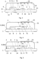
- Fig. 3 shows a cut view of a PA gas sensor device according to an embodiment of the invention.
- an EM radiation source 4 a pressure transducer 3 and a capacitor 51 are arranged on the first side 11 of a substrate 1 facing the measurement volume 21 defined by the substrate 1 and a measurement cell body 1 arranged on the same first side 11 of the substrate 1.
- a controller 8 embodied as ASIC is arranged on the very same first side 11 of the substrate 1, however is capped by cap 7.
- a venting hole 6 is provided through the substrate 1 for balancing pressure in the cap volume 71.
- the venting hole 6 is covered by a venting hole membrane 14 allowing gas from or into the cap volume 71 to pass.
- another sensor 9 is provided which advantageously is one or more of the following: a temperature sensor, a humidity sensor, a combined temperature/humidity sensor, a pressure sensor, in particular a barometric pressure sensor, another pressure transducer, another gas sensor, e.g. of metal oxide type or of electrochemical type.
- a gas concentration value may be compensated, e.g. for effects of temperature and/or humidity.
- the controller 8 in the cap volume 71 preferably is configured to compensate the value indicative of a presence or a concentration of the chemical component for the impact of the variable measured by the other sensor 9 and hence, dependent on measurement values of the other sensor 9. Hence effects of ambient conditions on the measurement of the chemical component can be reduced or eliminated.
- Fig. 4 shows a cut view of a PA gas sensor device according to a further embodiment of the present invention.
- the controller 8 is capped within the measurement cell, but also one or more other electrical components such as the capacitor 51 illustrated, as is the electromagnetic radiation source 4.
- the latter requires an optical window 72 in the cap 7.
- the optical window 72 enables the radiation emitted by the EM radiation source 4 to enter the measurement volume 21 and interact with the gas molecules of interest.
- the pressure transducer 3 remains arranged in the measurement volume 21 outside the cap volume 71. The pressure transducer 3 thus is enabled to detect the pressure variations induced by the reaction of the gas molecules with the emitted radiation.
- the other sensor 9 is a humidity sensor.
- the humidity sensor may provide its signal representing the humidity measured inside the measurement cell to the controller 8 which may be used to compensate the pressure transducer signal for humidity induced variations.
- the cap volume 71 is not connected to the outside world given that there is no venting hole.
- a venting hole may indeed be provided for the above reasons.
- Fig. 5 shows a cut view of a PA gas sensor device according to a further embodiment of the present invention.
- the other sensor 9 - again a humidity sensor - is now arranged under the cap 7, i.e. within the cap volume 71.
- the signal provided by the pressure transducer 3 again may be compensated by humidity variations.
- a venting hole 6 and a venting hole membrane 14 are provided for allowing venting the cap volume 71.
- the pressure transducer 3 is one of or even the only component not arranged in the capped volume 71. Such approach improves, i.e. increases a mean optical path length of the radiation 41 within the measurement volume 21.
- a material of the measurement cell body 2 is chosen to be reflective, such as a sheet metal.
- an inner surface of the measurement cell body 2 is coated with a reflective coating.
- the reflective coating may not only be arranged on an inner surface of the measurement cell body 2, but also on one or more of the following: parts of the first side 11 of the substrate 1; on parts of the pressure transducer 3, such as its top side; on the outer surface of the cap 7 facing the measurement volume 21. In this way, the overall reflectivity inside the measurement cell is increased, which leads to more accurate measurements of the concentration of the component.
Landscapes
- Physics & Mathematics (AREA)
- Biochemistry (AREA)
- General Physics & Mathematics (AREA)
- Life Sciences & Earth Sciences (AREA)
- Chemical & Material Sciences (AREA)
- Analytical Chemistry (AREA)
- Pathology (AREA)
- General Health & Medical Sciences (AREA)
- Health & Medical Sciences (AREA)
- Immunology (AREA)
- Optics & Photonics (AREA)
- Engineering & Computer Science (AREA)
- Signal Processing (AREA)
- Investigating Or Analysing Materials By Optical Means (AREA)
- Investigating Or Analyzing Materials By The Use Of Ultrasonic Waves (AREA)
Claims (13)
- Photoakustische Gassensorvorrichtung zur Bestimmung eines Wertes, der das Vorhandensein oder die Konzentration einer chemischen Komponente in einem Gas anzeigt, wobei die photoakustische Gassensorvorrichtung umfasst:- ein Substrat (1),- einen Messzellenkörper (2), der auf einer ersten Seite (11) des Substrats (1) angeordnet ist, wobei das Substrat (1) und der Messzellenkörper (2) eine Messzelle definieren,- eine Kappe (7), die auf der ersten Seite (11) des Substrats (1) innerhalb der Messzelle angeordnet ist, wobei die Kappe (7) und das Substrat (1) ein Kappenvolumen (71) definieren, und die Kappe (7) und das Substrat (1) das Kappenvolumen (71) akustisch abdichten,- ein Messvolumen (21), das durch den Messzellenkörper (2), das Substrat (1) und die Kappe (7) eingeschlossen ist,- eine Öffnung (23) in der Messzelle für den Eintritt des Gases in das Messvolumen (21),- elektrische Bauteile, die auf der ersten Seite (11) des Substrats (1) und in der Messzelle angeordnet sind, umfassend mindestens:- eine elektromagnetische Strahlungsquelle (4) zum Aussenden elektromagnetischer Strahlung (41) in das Messvolumen (21),- einen Druckwandler (3) zur Messung einer Schallwelle, die von der chemischen Komponente in Reaktion auf eine Absorption der elektromagnetischen Strahlung (41) durch die im Messvolumen (21) vorhandene chemische Komponente erzeugt wird,- eine Steuerung (8), die zur Steuerung der elektromagnetischen Strahlungsquelle (4) konfiguriert ist,wobei der Druckwandler (3) ausserhalb des Kappenvolumens (71) angeordnet ist,wobei die Steuerung (8) im Kappenvolumen (71) angeordnet ist,wobei die Steuerung (8) so konfiguriert ist, dass sie ein vom Druckwandler (3) geliefertes elektrisches Signal verarbeitet, das das Vorhandensein oder die Konzentration der chemischen Komponente im Gas anzeigt.
- Die photoakustische Gassensorvorrichtung nach Anspruch 1,wobei eine dem Messvolumen (21) zugewandte Oberfläche der Kappe (7) ein Reflexionsvermögen von mehr als 70 %, vorzugsweise mehr als 80 %, besonders bevorzugt mehr als 90 % aufweist, undwobei vorzugsweise eine innere Oberfläche des Messzellenkörpers (2) ein Reflexionsvermögen von mehr als 70 %, vorzugsweise mehr als 80 %, noch bevorzugter mehr als 90 % aufweist.
- Die photoakustische Gassensorvorrichtung nach einem der vorangehenden Ansprüche,
wobei eines oder mehrere der folgenden Elemente im Kappenvolumen (71) angeordnet sind: ein elektrisches Bauteil, das Druckschwankungen und/oder Wärmeschwankungen abgibt, ein mechanisch zu schützendes elektrisches Bauteil, ein elektrisches Bauteil mit einer Oberseite von mehr als 3 mm2 und ein elektrisches Bauteil, das Zugang zur Umgebung des photoakustischen Gassensors benötigt. - Die photoakustische Gassensorvorrichtung nach einem der vorangehenden Ansprüche,
wobei die Steuerung (8) in einer integrierten Schaltung implementiert ist, vorzugsweise wobei die integrierte Schaltung ein ASIC ist, noch bevorzugter, wobei die integrierte Schaltung ein nackter Chip oder ein Chip-Scale-Package ist. - Die photoakustische Gassensorvorrichtung nach einem der vorangehenden Ansprüche,
wobei mindestens ein passives elektrisches Bauelement, vorzugsweise ein Kondensator, ein Widerstand oder eine Spule, im Kappenvolumen (71) angeordnet ist. - Die photoakustische Gassensorvorrichtung nach einem der vorangehenden Ansprüche,
wobei mindestens ein Transistor, vorzugsweise ein Transistor eines Spannungsreglers, im Kappenvolumen (71) angeordnet ist. - Die photoakustische Gassensorvorrichtung nach einem der vorangehenden Ansprüche,wobei das Substrat (1) ein Entlüftungsloch (6) aufweist, das so angeordnet ist, dass es das Kappenvolumen (71) mit einer Umgebung der photoakustischen Gassensorvorrichtung verbindet,wobei mindestens ein weiterer Sensor (9) zum Erfassen eines Umgebungsparameters im Umgebungsgas der photoakustischen Gassensorvorrichtung, der dem weiteren Sensor (9) durch das Entlüftungsloch (6) zugeführt wird, im Kappenvolumen (71) angeordnet ist.
- Die photoakustische Gassensorvorrichtung nach Anspruch 7,
umfassend eine Entlüftungslochmembran (14), die das Entlüftungsloch (6) abdeckt. - Die photoakustische Gassensorvorrichtung nach Anspruch 7 oder Anspruch 8,
wobei die Steuerung (8) so konfiguriert ist, dass sie den Wert, der das Vorhandensein oder die Konzentration der chemischen Komponente im Gas anzeigt, in Abhängigkeit von einem elektrischen Signal, das vom Druckwandler (3) geliefert wird, und in Abhängigkeit von einem elektrischen Signal, das vom anderen Sensor (9) geliefert wird, bestimmt. - Die photoakustische Gassensorvorrichtung nach einem der vorangehenden Ansprüche,wobei die elektromagnetische Strahlungsquelle (4) im Kappenvolumen (71) angeordnet ist,wobei die Kappe (7) ein optisches Fenster (72) enthält, das so angeordnet und konfiguriert ist, dass es der von der elektromagnetischen Strahlungsquelle (4) emittierten Strahlung ermöglicht, in das Messvolumen (21) einzutreten, und/oder die von der elektromagnetischen Strahlungsquelle (4) emittierte Strahlung vor dem Eintritt in das Messvolumen (21) bandgefiltert wird.
- Die photoakustische Gassensorvorrichtung nach einem der vorangehenden Ansprüche 1 bis 9,wobei die elektromagnetische Strahlungsquelle (4) so konfiguriert ist, dass sie ultraviolette Strahlung emittiert,wobei die elektromagnetische Strahlungsquelle (4) ausserhalb des Kappenvolumens (71) angeordnet ist,wobei die Kappe (7) aus einem für ultraviolette Strahlung undurchsichtigen Material hergestellt ist, um die Steuerung (8) im Kappenvolumen (71) davor zu schützen.
- Die photoakustische Gassensorvorrichtung nach einem der vorangehenden Ansprüche,wobei die Kappe (7) ein elektrisch leitendes Material umfasst,vorzugsweise wobei die Kappe (7) aus Metall oder aus mit Metall beschichtetem Kunststoff hergestellt ist,vorzugsweise wobei der Messzellenkörper (2) aus Metall oder aus mit Metall beschichtetem Kunststoff hergestellt ist,vorzugsweise wobei die Kappe (7) und der Messzellenkörper (2) aus demselben Material hergestellt sind.
- Verfahren zur Herstellung einer photoakustischen Gassensorvorrichtung zur Bestimmung eines Wertes, der das Vorhandensein oder die Konzentration einer chemischen Komponente in einem Gas anzeigt, wobei das Verfahren umfasst:- Bereitstellen eines Substrats (1),- Bestücken einer ersten Seite (11) des Substrats (1) mit elektrischen Bauelementen, vorzugsweise in einem SMD-Verfahren, wobei die elektrischen Bauelemente mindestens umfassen:- eine elektromagnetische Strahlungsquelle (4) zum Aussenden elektromagnetischer Strahlung (41),- einen Druckwandler (3) zur Messung einer Schallwelle, die von der chemischen Komponente in Reaktion auf eine Absorption elektromagnetischer Strahlung (41) durch die chemische Komponente erzeugt wird,- eine Steuerung (8), die so konfiguriert ist, dass sie die elektromagnetische Strahlungsquelle (4) steuert, und die so konfiguriert ist, dass sie ein vom Druckwandler (3) geliefertes elektrisches Signal verarbeitet, das das Vorhandensein oder die Konzentration der chemischen Komponente im Gas anzeigt,- Anbringen einer Kappe (7) auf der ersten Seite (11) des Substrats (1), wobei die Kappe (7) und das Substrat (1) ein Kappenvolumen (71) akustisch abdichten und die Kappe (7) zumindest die Steuerung (8), nicht aber den Druckwandler (3) umschliesst,- Anbringen eines Messzellenkörpers (2) auf der ersten Seite (11) des Substrats (1), wodurch die Kappe (7) und elektrische Komponenten, die ausserhalb der Kappe (7) angeordnet sind, eingeschlossen werden, wobei der Messzellenkörper (2) und das Substrat (1) eine Messzelle bilden, wobei der Messzellenkörper (2), das Substrat (1) und die Kappe (7) ein Messvolumen (21) begrenzen, in das die elektromagnetische Strahlung (41) gesendet wird, und wobei die Messzelle eine Öffnung (23) für den Eintritt des Gases in das Messvolumen (21) aufweist.
Priority Applications (7)
| Application Number | Priority Date | Filing Date | Title |
|---|---|---|---|
| EP21161060.5A EP4053540B1 (de) | 2021-03-05 | 2021-03-05 | Photo-akustische gassensorvorrichtung |
| PCT/EP2022/054716 WO2022184553A1 (en) | 2021-03-05 | 2022-02-24 | Photoacoustic gas sensor device |
| US18/279,062 US20240230519A9 (en) | 2021-03-05 | 2022-02-24 | Photoacoustic gas sensor device |
| JP2023553604A JP2024508915A (ja) | 2021-03-05 | 2022-02-24 | 光音響ガスセンサ装置 |
| CN202280019167.5A CN117280195A (zh) | 2021-03-05 | 2022-02-24 | 光声气体传感器装置 |
| KR1020237033613A KR20230152135A (ko) | 2021-03-05 | 2022-02-24 | 광음향 가스 센서 디바이스 |
| EP22707745.0A EP4302072A1 (de) | 2021-03-05 | 2022-02-24 | Photoakustische gassensorvorrichtung |
Applications Claiming Priority (1)
| Application Number | Priority Date | Filing Date | Title |
|---|---|---|---|
| EP21161060.5A EP4053540B1 (de) | 2021-03-05 | 2021-03-05 | Photo-akustische gassensorvorrichtung |
Publications (3)
| Publication Number | Publication Date |
|---|---|
| EP4053540A1 EP4053540A1 (de) | 2022-09-07 |
| EP4053540B1 true EP4053540B1 (de) | 2024-10-16 |
| EP4053540C0 EP4053540C0 (de) | 2024-10-16 |
Family
ID=74859360
Family Applications (2)
| Application Number | Title | Priority Date | Filing Date |
|---|---|---|---|
| EP21161060.5A Active EP4053540B1 (de) | 2021-03-05 | 2021-03-05 | Photo-akustische gassensorvorrichtung |
| EP22707745.0A Pending EP4302072A1 (de) | 2021-03-05 | 2022-02-24 | Photoakustische gassensorvorrichtung |
Family Applications After (1)
| Application Number | Title | Priority Date | Filing Date |
|---|---|---|---|
| EP22707745.0A Pending EP4302072A1 (de) | 2021-03-05 | 2022-02-24 | Photoakustische gassensorvorrichtung |
Country Status (6)
| Country | Link |
|---|---|
| US (1) | US20240230519A9 (de) |
| EP (2) | EP4053540B1 (de) |
| JP (1) | JP2024508915A (de) |
| KR (1) | KR20230152135A (de) |
| CN (1) | CN117280195A (de) |
| WO (1) | WO2022184553A1 (de) |
Families Citing this family (2)
| Publication number | Priority date | Publication date | Assignee | Title |
|---|---|---|---|---|
| CN116165146A (zh) * | 2023-02-28 | 2023-05-26 | 西安交通大学 | 一种光声光谱式多气体mems微型气体传感器 |
| CN118465056B (zh) * | 2024-07-12 | 2024-11-08 | 上海先普气体技术有限公司 | 气体浓度测量装置 |
Family Cites Families (9)
| Publication number | Priority date | Publication date | Assignee | Title |
|---|---|---|---|---|
| US8695402B2 (en) * | 2010-06-03 | 2014-04-15 | Honeywell International Inc. | Integrated IR source and acoustic detector for photoacoustic gas sensor |
| DE202015002315U1 (de) * | 2015-03-27 | 2015-05-06 | Infineon Technologies Ag | Gassensor |
| DE102015106373B4 (de) * | 2015-04-24 | 2023-03-02 | Infineon Technologies Ag | Photoakustisches gassensormodul mit lichtemittereinheit und einer detektoreinheit |
| US10302554B2 (en) * | 2016-06-03 | 2019-05-28 | Ingineon Technologies Ag | Acoustic wave detector |
| JP6751156B2 (ja) * | 2016-11-28 | 2020-09-02 | 京セラ株式会社 | センサ用配線基板、センサ用パッケージおよびセンサ装置 |
| EP3614126A1 (de) * | 2019-05-17 | 2020-02-26 | Sensirion AG | Photo-akustische gassensorvorrichtung |
| JP7365812B2 (ja) * | 2019-08-07 | 2023-10-20 | 日清紡マイクロデバイス株式会社 | センサ装置およびその製造方法 |
| EP3798607B1 (de) * | 2019-08-09 | 2023-01-25 | Sensirion AG | Photo-akustische gassensorvorrichtungen |
| DE102019134267A1 (de) * | 2019-12-13 | 2021-06-17 | Infineon Technologies Ag | Photoakustische Detektoreinheit, photoakustischer Sensor und zugehörige Herstellungsverfahren |
-
2021
- 2021-03-05 EP EP21161060.5A patent/EP4053540B1/de active Active
-
2022
- 2022-02-24 WO PCT/EP2022/054716 patent/WO2022184553A1/en not_active Ceased
- 2022-02-24 CN CN202280019167.5A patent/CN117280195A/zh active Pending
- 2022-02-24 JP JP2023553604A patent/JP2024508915A/ja active Pending
- 2022-02-24 US US18/279,062 patent/US20240230519A9/en active Pending
- 2022-02-24 KR KR1020237033613A patent/KR20230152135A/ko active Pending
- 2022-02-24 EP EP22707745.0A patent/EP4302072A1/de active Pending
Also Published As
| Publication number | Publication date |
|---|---|
| US20240133801A1 (en) | 2024-04-25 |
| EP4302072A1 (de) | 2024-01-10 |
| WO2022184553A1 (en) | 2022-09-09 |
| KR20230152135A (ko) | 2023-11-02 |
| CN117280195A (zh) | 2023-12-22 |
| US20240230519A9 (en) | 2024-07-11 |
| JP2024508915A (ja) | 2024-02-28 |
| EP4053540A1 (de) | 2022-09-07 |
| EP4053540C0 (de) | 2024-10-16 |
Similar Documents
| Publication | Publication Date | Title |
|---|---|---|
| EP3550286B1 (de) | Photo-akustische gassensorvorrichtung | |
| US4898031A (en) | Vibrational angular velocity sensor | |
| EP4007908B1 (de) | Photo-akustische gassensorvorrichtung | |
| KR101837073B1 (ko) | 광음향 기체 센서를 위한 통합된 ir 소스 및 음향 검출기 | |
| JPH11132857A (ja) | 赤外線検出器 | |
| EP4053540B1 (de) | Photo-akustische gassensorvorrichtung | |
| US20220236230A1 (en) | Photoacoustic gas sensor device | |
| CN112938891B (zh) | 用于光声传感器的发射器封装件 | |
| EP0866955A1 (de) | Eine vielzahl photoleitender detektoren in einer kompakten verpackung zusammenfassende matrixanordnung | |
| JPH10318829A (ja) | 赤外線センサ | |
| JP2007225455A (ja) | 赤外線検出器 | |
| JP2003270047A (ja) | 赤外線センサ | |
| JPH09178596A (ja) | 圧力センサ | |
| JPH10332506A (ja) | 半導体圧力センサ | |
| JP4925258B2 (ja) | 赤外線検出器 | |
| JP2001159566A (ja) | 赤外線センサ及び耳式体温計 |
Legal Events
| Date | Code | Title | Description |
|---|---|---|---|
| PUAI | Public reference made under article 153(3) epc to a published international application that has entered the european phase |
Free format text: ORIGINAL CODE: 0009012 |
|
| STAA | Information on the status of an ep patent application or granted ep patent |
Free format text: STATUS: THE APPLICATION HAS BEEN PUBLISHED |
|
| AK | Designated contracting states |
Kind code of ref document: A1 Designated state(s): AL AT BE BG CH CY CZ DE DK EE ES FI FR GB GR HR HU IE IS IT LI LT LU LV MC MK MT NL NO PL PT RO RS SE SI SK SM TR |
|
| STAA | Information on the status of an ep patent application or granted ep patent |
Free format text: STATUS: REQUEST FOR EXAMINATION WAS MADE |
|
| 17P | Request for examination filed |
Effective date: 20230301 |
|
| RBV | Designated contracting states (corrected) |
Designated state(s): AL AT BE BG CH CY CZ DE DK EE ES FI FR GB GR HR HU IE IS IT LI LT LU LV MC MK MT NL NO PL PT RO RS SE SI SK SM TR |
|
| P01 | Opt-out of the competence of the unified patent court (upc) registered |
Effective date: 20230602 |
|
| GRAP | Despatch of communication of intention to grant a patent |
Free format text: ORIGINAL CODE: EPIDOSNIGR1 |
|
| STAA | Information on the status of an ep patent application or granted ep patent |
Free format text: STATUS: GRANT OF PATENT IS INTENDED |
|
| RIC1 | Information provided on ipc code assigned before grant |
Ipc: G01N 29/24 20060101ALI20240524BHEP Ipc: G01N 21/17 20060101AFI20240524BHEP |
|
| INTG | Intention to grant announced |
Effective date: 20240613 |
|
| GRAS | Grant fee paid |
Free format text: ORIGINAL CODE: EPIDOSNIGR3 |
|
| GRAA | (expected) grant |
Free format text: ORIGINAL CODE: 0009210 |
|
| STAA | Information on the status of an ep patent application or granted ep patent |
Free format text: STATUS: THE PATENT HAS BEEN GRANTED |
|
| AK | Designated contracting states |
Kind code of ref document: B1 Designated state(s): AL AT BE BG CH CY CZ DE DK EE ES FI FR GB GR HR HU IE IS IT LI LT LU LV MC MK MT NL NO PL PT RO RS SE SI SK SM TR |
|
| REG | Reference to a national code |
Ref country code: GB Ref legal event code: FG4D |
|
| REG | Reference to a national code |
Ref country code: CH Ref legal event code: EP |
|
| REG | Reference to a national code |
Ref country code: IE Ref legal event code: FG4D |
|
| REG | Reference to a national code |
Ref country code: DE Ref legal event code: R096 Ref document number: 602021020211 Country of ref document: DE |
|
| U01 | Request for unitary effect filed |
Effective date: 20241016 |
|
| U07 | Unitary effect registered |
Designated state(s): AT BE BG DE DK EE FI FR IT LT LU LV MT NL PT RO SE SI Effective date: 20241022 |
|
| P04 | Withdrawal of opt-out of the competence of the unified patent court (upc) registered |
Free format text: CASE NUMBER: APP_56893/2024 Effective date: 20241018 |
|
| PG25 | Lapsed in a contracting state [announced via postgrant information from national office to epo] |
Ref country code: IS Free format text: LAPSE BECAUSE OF FAILURE TO SUBMIT A TRANSLATION OF THE DESCRIPTION OR TO PAY THE FEE WITHIN THE PRESCRIBED TIME-LIMIT Effective date: 20250216 Ref country code: HR Free format text: LAPSE BECAUSE OF FAILURE TO SUBMIT A TRANSLATION OF THE DESCRIPTION OR TO PAY THE FEE WITHIN THE PRESCRIBED TIME-LIMIT Effective date: 20241016 |
|
| PG25 | Lapsed in a contracting state [announced via postgrant information from national office to epo] |
Ref country code: ES Free format text: LAPSE BECAUSE OF FAILURE TO SUBMIT A TRANSLATION OF THE DESCRIPTION OR TO PAY THE FEE WITHIN THE PRESCRIBED TIME-LIMIT Effective date: 20241016 |
|
| PG25 | Lapsed in a contracting state [announced via postgrant information from national office to epo] |
Ref country code: NO Free format text: LAPSE BECAUSE OF FAILURE TO SUBMIT A TRANSLATION OF THE DESCRIPTION OR TO PAY THE FEE WITHIN THE PRESCRIBED TIME-LIMIT Effective date: 20250116 |
|
| PG25 | Lapsed in a contracting state [announced via postgrant information from national office to epo] |
Ref country code: GR Free format text: LAPSE BECAUSE OF FAILURE TO SUBMIT A TRANSLATION OF THE DESCRIPTION OR TO PAY THE FEE WITHIN THE PRESCRIBED TIME-LIMIT Effective date: 20250117 |
|
| PG25 | Lapsed in a contracting state [announced via postgrant information from national office to epo] |
Ref country code: PL Free format text: LAPSE BECAUSE OF FAILURE TO SUBMIT A TRANSLATION OF THE DESCRIPTION OR TO PAY THE FEE WITHIN THE PRESCRIBED TIME-LIMIT Effective date: 20241016 |
|
| PGFP | Annual fee paid to national office [announced via postgrant information from national office to epo] |
Ref country code: GB Payment date: 20250324 Year of fee payment: 5 |
|
| PG25 | Lapsed in a contracting state [announced via postgrant information from national office to epo] |
Ref country code: RS Free format text: LAPSE BECAUSE OF FAILURE TO SUBMIT A TRANSLATION OF THE DESCRIPTION OR TO PAY THE FEE WITHIN THE PRESCRIBED TIME-LIMIT Effective date: 20250116 |
|
| U20 | Renewal fee for the european patent with unitary effect paid |
Year of fee payment: 5 Effective date: 20250325 |
|
| PG25 | Lapsed in a contracting state [announced via postgrant information from national office to epo] |
Ref country code: SM Free format text: LAPSE BECAUSE OF FAILURE TO SUBMIT A TRANSLATION OF THE DESCRIPTION OR TO PAY THE FEE WITHIN THE PRESCRIBED TIME-LIMIT Effective date: 20241016 |
|
| PGFP | Annual fee paid to national office [announced via postgrant information from national office to epo] |
Ref country code: CH Payment date: 20250401 Year of fee payment: 5 |
|
| PG25 | Lapsed in a contracting state [announced via postgrant information from national office to epo] |
Ref country code: SK Free format text: LAPSE BECAUSE OF FAILURE TO SUBMIT A TRANSLATION OF THE DESCRIPTION OR TO PAY THE FEE WITHIN THE PRESCRIBED TIME-LIMIT Effective date: 20241016 |
|
| PG25 | Lapsed in a contracting state [announced via postgrant information from national office to epo] |
Ref country code: CZ Free format text: LAPSE BECAUSE OF FAILURE TO SUBMIT A TRANSLATION OF THE DESCRIPTION OR TO PAY THE FEE WITHIN THE PRESCRIBED TIME-LIMIT Effective date: 20241016 |
|
| PLBE | No opposition filed within time limit |
Free format text: ORIGINAL CODE: 0009261 |
|
| STAA | Information on the status of an ep patent application or granted ep patent |
Free format text: STATUS: NO OPPOSITION FILED WITHIN TIME LIMIT |
|
| 26N | No opposition filed |
Effective date: 20250717 |
|
| PG25 | Lapsed in a contracting state [announced via postgrant information from national office to epo] |
Ref country code: MC Free format text: LAPSE BECAUSE OF FAILURE TO SUBMIT A TRANSLATION OF THE DESCRIPTION OR TO PAY THE FEE WITHIN THE PRESCRIBED TIME-LIMIT Effective date: 20241016 |