EP4053483A1 - Four rotatif et procédé de cuisson du produit contenant des carbonates, en particulier calcaire ou dolomite - Google Patents
Four rotatif et procédé de cuisson du produit contenant des carbonates, en particulier calcaire ou dolomite Download PDFInfo
- Publication number
- EP4053483A1 EP4053483A1 EP21161137.1A EP21161137A EP4053483A1 EP 4053483 A1 EP4053483 A1 EP 4053483A1 EP 21161137 A EP21161137 A EP 21161137A EP 4053483 A1 EP4053483 A1 EP 4053483A1
- Authority
- EP
- European Patent Office
- Prior art keywords
- zone
- rotary kiln
- rotary
- rotary tube
- projections
- Prior art date
- Legal status (The legal status is an assumption and is not a legal conclusion. Google has not performed a legal analysis and makes no representation as to the accuracy of the status listed.)
- Withdrawn
Links
- 235000019738 Limestone Nutrition 0.000 title claims abstract description 9
- 239000010459 dolomite Substances 0.000 title claims abstract description 9
- 229910000514 dolomite Inorganic materials 0.000 title claims abstract description 9
- 239000006028 limestone Substances 0.000 title claims abstract description 9
- 238000000034 method Methods 0.000 title claims abstract description 8
- 238000010304 firing Methods 0.000 title description 4
- 239000003575 carbonaceous material Substances 0.000 title 1
- 239000000463 material Substances 0.000 claims abstract description 95
- BVKZGUZCCUSVTD-UHFFFAOYSA-L Carbonate Chemical compound [O-]C([O-])=O BVKZGUZCCUSVTD-UHFFFAOYSA-L 0.000 claims abstract description 9
- 238000007599 discharging Methods 0.000 claims abstract description 3
- 238000001816 cooling Methods 0.000 claims description 12
- 239000011819 refractory material Substances 0.000 claims description 6
- 239000002184 metal Substances 0.000 claims description 4
- 238000002156 mixing Methods 0.000 description 13
- 238000001354 calcination Methods 0.000 description 9
- 238000002485 combustion reaction Methods 0.000 description 6
- 210000001035 gastrointestinal tract Anatomy 0.000 description 5
- 230000015572 biosynthetic process Effects 0.000 description 3
- 239000000428 dust Substances 0.000 description 3
- 230000005484 gravity Effects 0.000 description 3
- CURLTUGMZLYLDI-UHFFFAOYSA-N Carbon dioxide Chemical compound O=C=O CURLTUGMZLYLDI-UHFFFAOYSA-N 0.000 description 2
- 241000826860 Trapezium Species 0.000 description 2
- 230000001154 acute effect Effects 0.000 description 2
- 239000000969 carrier Substances 0.000 description 2
- 238000013461 design Methods 0.000 description 2
- 238000012360 testing method Methods 0.000 description 2
- 230000007704 transition Effects 0.000 description 2
- 206010006784 Burning sensation Diseases 0.000 description 1
- 229910002092 carbon dioxide Inorganic materials 0.000 description 1
- 239000001569 carbon dioxide Substances 0.000 description 1
- 238000006243 chemical reaction Methods 0.000 description 1
- 210000001520 comb Anatomy 0.000 description 1
- 238000010276 construction Methods 0.000 description 1
- 238000011161 development Methods 0.000 description 1
- 238000006073 displacement reaction Methods 0.000 description 1
- 238000011835 investigation Methods 0.000 description 1
- 238000013021 overheating Methods 0.000 description 1
- 230000002093 peripheral effect Effects 0.000 description 1
Images


Classifications
-
- F—MECHANICAL ENGINEERING; LIGHTING; HEATING; WEAPONS; BLASTING
- F27—FURNACES; KILNS; OVENS; RETORTS
- F27B—FURNACES, KILNS, OVENS, OR RETORTS IN GENERAL; OPEN SINTERING OR LIKE APPARATUS
- F27B7/00—Rotary-drum furnaces, i.e. horizontal or slightly inclined
- F27B7/14—Rotary-drum furnaces, i.e. horizontal or slightly inclined with means for agitating or moving the charge
- F27B7/16—Rotary-drum furnaces, i.e. horizontal or slightly inclined with means for agitating or moving the charge the means being fixed relatively to the drum, e.g. composite means
- F27B7/161—Rotary-drum furnaces, i.e. horizontal or slightly inclined with means for agitating or moving the charge the means being fixed relatively to the drum, e.g. composite means the means comprising projections jutting out from the wall
- F27B7/162—Rotary-drum furnaces, i.e. horizontal or slightly inclined with means for agitating or moving the charge the means being fixed relatively to the drum, e.g. composite means the means comprising projections jutting out from the wall the projections consisting of separate lifting elements, e.g. lifting shovels
-
- C—CHEMISTRY; METALLURGY
- C04—CEMENTS; CONCRETE; ARTIFICIAL STONE; CERAMICS; REFRACTORIES
- C04B—LIME, MAGNESIA; SLAG; CEMENTS; COMPOSITIONS THEREOF, e.g. MORTARS, CONCRETE OR LIKE BUILDING MATERIALS; ARTIFICIAL STONE; CERAMICS; REFRACTORIES; TREATMENT OF NATURAL STONE
- C04B7/00—Hydraulic cements
- C04B7/36—Manufacture of hydraulic cements in general
- C04B7/43—Heat treatment, e.g. precalcining, burning, melting; Cooling
- C04B7/432—Preheating without addition of fuel
-
- C—CHEMISTRY; METALLURGY
- C04—CEMENTS; CONCRETE; ARTIFICIAL STONE; CERAMICS; REFRACTORIES
- C04B—LIME, MAGNESIA; SLAG; CEMENTS; COMPOSITIONS THEREOF, e.g. MORTARS, CONCRETE OR LIKE BUILDING MATERIALS; ARTIFICIAL STONE; CERAMICS; REFRACTORIES; TREATMENT OF NATURAL STONE
- C04B7/00—Hydraulic cements
- C04B7/36—Manufacture of hydraulic cements in general
- C04B7/43—Heat treatment, e.g. precalcining, burning, melting; Cooling
- C04B7/44—Burning; Melting
-
- F—MECHANICAL ENGINEERING; LIGHTING; HEATING; WEAPONS; BLASTING
- F27—FURNACES; KILNS; OVENS; RETORTS
- F27B—FURNACES, KILNS, OVENS, OR RETORTS IN GENERAL; OPEN SINTERING OR LIKE APPARATUS
- F27B7/00—Rotary-drum furnaces, i.e. horizontal or slightly inclined
- F27B7/10—Rotary-drum furnaces, i.e. horizontal or slightly inclined internally heated, e.g. by means of passages in the wall
-
- F—MECHANICAL ENGINEERING; LIGHTING; HEATING; WEAPONS; BLASTING
- F27—FURNACES; KILNS; OVENS; RETORTS
- F27B—FURNACES, KILNS, OVENS, OR RETORTS IN GENERAL; OPEN SINTERING OR LIKE APPARATUS
- F27B7/00—Rotary-drum furnaces, i.e. horizontal or slightly inclined
- F27B7/20—Details, accessories, or equipment peculiar to rotary-drum furnaces
- F27B7/22—Rotary drums; Supports therefor
- F27B7/224—Discharge ends
-
- Y—GENERAL TAGGING OF NEW TECHNOLOGICAL DEVELOPMENTS; GENERAL TAGGING OF CROSS-SECTIONAL TECHNOLOGIES SPANNING OVER SEVERAL SECTIONS OF THE IPC; TECHNICAL SUBJECTS COVERED BY FORMER USPC CROSS-REFERENCE ART COLLECTIONS [XRACs] AND DIGESTS
- Y02—TECHNOLOGIES OR APPLICATIONS FOR MITIGATION OR ADAPTATION AGAINST CLIMATE CHANGE
- Y02P—CLIMATE CHANGE MITIGATION TECHNOLOGIES IN THE PRODUCTION OR PROCESSING OF GOODS
- Y02P40/00—Technologies relating to the processing of minerals
- Y02P40/40—Production or processing of lime, e.g. limestone regeneration of lime in pulp and sugar mills
Definitions
- the invention relates to a rotary kiln for burning material containing carbonate, in particular limestone or dolomite, comprising a rotary kiln with an inlet end for feeding in the material to be burned and an outlet end for discharging the burned material, and a burner unit arranged in the area of the outlet end, with the rotary kiln on has an inlet zone at its inlet end and an outlet zone at its outlet end, a preheating zone and a combustion zone being arranged between the inlet zone and outlet zone in the transport direction of the material. Furthermore, the present invention relates to a method for burning carbonate-containing material, in particular limestone and dolomite, in such a rotary kiln.
- Rotary kilns for burning carbonate-containing material have been known from the prior art for decades and have proven themselves as an efficiently and reliably working kiln type for the continuous calcination of various types of materials.
- Printed prior art can be found, for example, in EP 0 674 145 A1 , US 1,544,504A , or the US 3,124,338A .
- the central component of a rotary kiln is a long cylindrical rotary kiln (often 100 m or longer), which is typically inclined at about 2 to 7% to the horizontal.
- the rotary tube rotates slowly around its axis at 0.5 to 1.5 rpm and the material to be burned, which is introduced into the rotary tube at its inlet end by means of a screw conveyor or similar, moves slowly through the rotary tube due to gravity in the direction of an im Burners arranged in the area of the kiln outlet produced a flame.
- the kiln is usually filled with the material to be fired up to about 8 to 20% of the kiln diameter.
- the material to be burned moves from the inlet zone, which is usually a few meters long, into the preheating zone (partially also referred to as the transition zone), in which temperatures of approx. 1100 - 1200 °C are already present, and from there into an extended combustion zone, which is characterized by maximum temperatures of 1500 - 1600 °C.
- the preheating zone partially also referred to as the transition zone
- an extended combustion zone which is characterized by maximum temperatures of 1500 - 1600 °C.
- the firing zone is followed by the several meter long outlet zone of the rotary kiln, in which the fired material begins to cool down. From there, the fired material usually falls through a chute onto a cooling unit, for example a grate cooler.
- the specific lengths of each zone also depend on the overall length of the rotary kiln and the relative position of the burner lance and flame length.
- Efficient kiln operation always strives for high throughput rates while ensuring that calcination of the material to be fired is complete and all carbon dioxide is removed from the material. Thorough mixing of the material to be burned is of decisive importance for rapid and complete calcination.
- Another problem in practical operation is the non-uniform temperature distribution in the fired material, which is a direct consequence of the mixing characteristics of the material in a rotary kiln.
- an active part forms on the surface of the free furnace volume, which is actively in motion during the rotation of the rotary kiln and is in intensive temperature exchange with the furnace atmosphere, while a passive part underneath tends to form clusters and does not reach the surface.
- the active part in the material bed in the outlet zone can cool down quickly, while the passive part maintains a high temperature level for a long time due to a lack of exchange with the furnace atmosphere cooling down in the outlet zone. This can lead to very hot burnt material from the passive part of the material bed damaging the cooling device downstream of the rotary kiln through overheating.
- carbonate-containing material in particular limestone or dolomite
- damage to the components following the rotary tube, in particular those for cooling the fired material should be avoided as a result of the fired material being at too high a temperature.
- the above-mentioned object is achieved with a rotary tube furnace according to the preamble of claim 1 in that at least one projection is arranged in the outlet zone of the rotary tube, the at least one projection having a contour that tapers in the direction of rotation of the rotary tube .
- the particular advantage of the rotary kiln according to the invention is that by arranging at least one projection in the outlet zone, the fired material is effectively mixed along the entire depth of the material bed, so that there is an intensive temperature exchange not only in the active but also in the passive part of the material with the furnace atmosphere cooling down in the outlet zone. This in turn means that no temperature peaks occur in the material, so that temperature-related damage to the components following the rotary tube, in particular the cooling units, by the fired material is minimized.
- the at least one projection has a contour that tapers in the direction of rotation of the rotary tube, it moves like a plow through the material and intensively mixes and combs through it. This achieves maximum mixing and completely eliminates the division of the material bed into active and passive parts.
- the at least one projection contains a refractory material.
- a refractory material is particularly suitable as a refractory material, especially refractory concrete, as is known per se to a person skilled in the art.
- the at least one projection has a contour that tapers in the direction of rotation of the rotary tube. It is preferably V-shaped, with the tip of the “V” being aligned in the direction of rotation of the rotary tube and thus plowing through the burned material to be mixed.
- the tapering contour can also be embodied by a prismatic geometry, in particular the geometry of a triangular prism, preferably an isosceles triangular prism.
- the geometry of a truncated pyramid is also possible, with one edge of the truncated pyramid preferably being arranged in the direction of rotation of the rotary tube in order to form the contour that tapers in the direction of rotation of the rotary tube.
- the edges of the triangular prism or the truncated pyramid can be blunted or rounded off in order to prevent sensitive edges from crumbling during furnace operation.
- the at least one projection advantageously has a height in relation to the rotary kiln in the radial direction of between 50 mm and 500 mm, preferably between 100 mm and 300 mm and particularly preferably approx. 200mm, on.
- the at least one projection can have a length in the circumferential direction of the rotary tube of between 50 mm and 2000 mm, in particular between 100 mm and 1000 mm, preferably between 300 mm and 500 mm and very particularly preferably of approx. 400 mm.
- the maximum width of the at least one projection in the longitudinal direction of the rotary tube can be between 50 mm and 600 mm, preferably between 300 mm and 500 mm and particularly preferably approximately 400 mm.
- the at least one projection provided according to the invention in the outlet zone can be permanently connected to the inner lining of the rotary tube.
- a further advantageous embodiment of the invention provides that the at least one projection is fastened to the inner rotary kiln shell by means of a metal anchor, in particular a welded-on metal anchor.
- a plurality of projections is provided in the run-out zone, the projections being distributed over the circumference of the rotary tube in groups of 1 to 10, specifically 3 to 7, preferably 4 to 6 projections are arranged.
- the projections of a group of projections are offset in the longitudinal direction of the rotary tube in alternation, for example in the manner of a zigzag line. Furthermore, a plurality of groups of projections can be arranged one behind the other in the longitudinal direction of the rotary tube. Both measures further increase the effectiveness of the mixing of the fired material in the outlet zone.
- an edge section is provided at the outlet end of the rotary tube, in which no projection is arranged.
- a plurality of further projections are arranged in the preheating zone of the rotary tube, the further projections being arranged one behind the other as groups essentially parallel to the longitudinal axis of the rotary tube.
- each of the further projections preferably all of them, each contain a refractory material.
- This can involve various high-temperature-resistant materials, as is known per se from the prior art. Concrete, in particular refractory concrete, has proven to be particularly suitable.
- Prismatic geometries are preferred, in particular in the form of a trapezoidal prism, especially an isosceles trapezoidal prism.
- a trapezoidal prism is preferably aligned parallel to the longitudinal extension of the rotary tube and accordingly has two side surfaces inclined to the radius of the rotary tube. These can enclose an angle to the base of the trapezium of between 35° and 75° and preferably between 60° and 70°.
- the length of such a trapezoidal prism in the longitudinal direction of the rotary tube is preferably about 400 mm and the height is preferably about 200 mm.
- the width of the lower trapezoidal base is preferably approx. 200 mm and the width of the upper base is preferably approx. 100 mm.
- the groups provided according to the invention of further projections arranged one behind the other essentially parallel to the longitudinal axis of the rotary tube can be arranged along the entire length of the preheating zone. According to a particularly advantageous embodiment of the invention, it is provided that the groups of projections extend over one-fifth to one-third of the total length of the rotary tube.
- At least one additional projection preferably a plurality of additional projections, is provided in the inlet zone of the rotary tube, the at least one additional projection having at least one sliding surface inclined to the longitudinal axis of the rotary tube for conveying of the material to be burned from the inlet zone to the preheating zone.
- the sliding surface of the at least one further projection has an inclination of 15° to 70° to the longitudinal axis of the rotary tube. Particularly good results were achieved with an angle of inclination of between 40° and 50°, specifically around 45°.
- the at least one additional projection can also contain a refractory material. This can involve various high-temperature-resistant materials, as is known per se from the prior art. Concrete, in particular refractory concrete, has proven to be particularly suitable.
- Prismatic geometries are preferred, in particular in the form of a right prism with a triangular base, especially in the form of a right-angled triangle, in which the at least one sliding surface is formed by the hypotenuse of the right-angled triangle.
- the height of the at least one additional projection is important for particularly good effectiveness in relation to the promotion of the material to be burned from the inlet zone in the direction of the preheating zone.
- This can be 100 mm to 500 mm, preferably 150 mm to 250 mm, typically about 200 mm. This ensures that a sufficient amount of material rests on the at least one sliding surface of the at least one additional projection and subsequently slides in the direction of the preheating zone due to the inclination of the sliding surface.
- the at least one additional projection has a length of 100 mm to 2000 mm, preferably 350 mm to 450 mm, typically approx. 400 mm, extending essentially parallel to the longitudinal axis of the rotary tube.
- the at least one additional projection can be attached to the inner rotary kiln shell by means of a welded metallic anchor.
- a common sliding surface is provided by a plurality of additional projections lined up as a group, a particularly long sliding surface can be provided on the one hand, which extends practically along the entire extent of the inlet zone.
- the plurality of additional projections are preferably formed substantially identically to one another.
- a further improvement in the conveyance of the material to be burned through the inlet zone of the rotary kiln is achieved in that over the circumference of the rotary kiln 2 to 8, in particular 4 to 6 and very particularly preferably 5 additional projections or groups of additional projections lined up next to one another are arranged.
- an efficient firing process is proposed, which is characterized by a high material throughput through the rotary kiln, a consistently high product quality in the fired material as a result of complete calcination, and easy implementation.
- thorough mixing of the fired material is achieved in the discharge zone of the rotary kiln, so that even cooling of the entire fired material begins in the discharge zone.
- the following system components in particular coolers and transport chutes, but in particular the following conveyor belts, are protected from temperature peaks.
- In 1 1 shows the rotary tube 1 of a rotary kiln with the usual storage and drive components, which are not discussed in more detail below.
- the rotary tube 1 comprises an inlet end 2a and a rear outlet end 4a--shown here on the front side.
- the rotary kiln 1 comprises an inlet zone 2, a preheating zone 3a (also called “transition zone”), a combustion zone 3b and a discharge zone 4 (see also 2 and 5 ).
- a burner lance 5 is arranged in the region of the outlet end 4a, by means of which a flame protruding into the rotary kiln 1 is generated during operation of the rotary kiln.
- the rotary kiln 1 has a total length of approx. 90 m, with the length of the inlet zone 2 approx. 2 m, that of the preheating zone 3a approx. 32 m, the length of the combustion zone 3b approx. 53 m and that of the outlet zone 4 is approx. 3 m. It goes without saying that these length specifications are to be understood purely as examples. Rotary tubes with different dimensions are also known from the prior art. The highest temperatures generated by the burner flame are achieved in the operation of the rotary kiln in the combustion zone 3b and amount to approx. 1500-1600° C., so that the vast majority of the calcination reaction takes place in this zone.
- the rotary tube 1 in the outlet zone 4 of the rotary tube 1 comprises a plurality of projections 8 which are arranged in groups 81 over the circumference of the rotary tube 1 .
- Each projection 8 in turn has a contour that tapers in the direction of rotation D of the rotary tube 1, as shown in the detailed drawings of FIG 3 and 4 is shown in more detail.
- the tapering contour of the projections 8 (technically also called "swords") is designed as a truncated pyramid with the base of an isosceles acute-angled triangle (see Fig. 4 ), the acute angle leading in the direction of rotation D of the rotary tube 1 and being slightly truncated for reasons of stability.
- This shape of the projections 8 makes it possible to comb through the fired product in the run-out zone 4 in the manner of a plow, which results in intensive mixing. This in turn means that no temperature peaks occur in the material, so that the risk of temperature-related damage to the components (not shown) following the rotary tube 1, in particular the cooling units, by the fired material is minimized.
- the projections 8 contain refractory concrete in the present case. Furthermore, each projection 8 is welded to the inner wall of the rotary tube 1 by means of a metallic anchor.
- a group 81 of projections 8 comprises six projections, which in the present case are offset in an alternating manner in the longitudinal direction of the rotary tube. This is in figure 5 indicated by a zigzag line V'.
- figure 5 shows, in the longitudinal direction of the rotary tube 1 a plurality of groups 81 - in this case three - of projections 8 are arranged one behind the other, with the group at the edge in relation to the outlet end 4a of the rotary tube 1 comprising only 3 projections 8 .
- the alternating displacement of the projections 8 of a group 81 further increases the effectiveness of the mixing of the fired material in the outlet zone 4 .
- An approximately 400 mm wide edge section 4b is provided between the outlet end 4a of the rotary tube 1 and the peripheral group 81 of only three projections 8, in which no projection 8 is arranged so that the original discharge position in the cooler shaft is not changed by the projections 8 .
- FIG 5 further shows, in the preheating zone 3a of the rotary tube 1 there are a plurality of further projections 7 (technically “carriers”), the further projections 7 being arranged one behind the other as groups 71 essentially parallel to the longitudinal axis of the rotary tube 1 .
- further projections 7 of adjacent groups 71 arranged adjacent in the circumferential direction of the rotary tube 1 are arranged alternately offset from one another in the longitudinal direction of the rotary tube 1, as represented by the zigzag line V. Due to this alternately offset arrangement, spiral transport paths S (in figure 5 shown as sloping lines) for the material to be burned. These serve to transport the material to be burned through the preheating zone 3a more quickly and with improved mixing while using constant energy.
- the groups 71 of further projections 7 arranged one behind the other in the longitudinal direction of the rotary kiln 1 can extend over one third to one fifth of the total length of the rotary kiln extend.
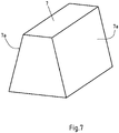
- these further projections 7 (“carriers") have the shape of a trapezoidal prism with inclined side surfaces 7a and a length of about 400 mm in the present case and a height of about 200 mm in the present case.
- the angle of inclination of the leg surfaces 7a to the lower trapezium base is approximately 76° in the present case.
- the trapezoidal design of the projections 7 ensures that the material mixed during furnace operation by the projections 7 in the preheating zone 3a does not fall off the projections 7 with increased formation of dust, but slides down along the side surfaces 7a.
- the group 61 of the present six rows of additional projections 6 are essentially identical to one another and point according to FIG 9 present essentially in the form of a triangular prism with the base of a right-angled, isosceles triangle, the acute angles of the triangle being truncated for reasons of stability.
- Each additional projection 6 has a sliding surface 6a, which is arranged at an angle to the longitudinal axis of the rotary tube 1. An angle of inclination of approximately 45° is preferably chosen.
- the additional projections 6 are lined up in a stepped manner in such a way that the individual sliding surfaces 6a of the additional projections 6 form a common sliding surface 6a*, which is also at an angle of approx. 45° to the longitudinal axis of the Rotary tube 1 is inclined.
- the sliding surfaces 6a of the additional projections 6 and accordingly the common sliding surface 6a* relative to the direction of rotation D of the rotary tube 1 are such aligned so that during operation of the furnace the material to be burned comes to rest on the sliding surfaces 6a, 6a*, and due to the selected inclination of the sliding surfaces 6a, 6a* to the longitudinal axis of the rotary tube 1, due to gravity, slides quickly in the direction of the preheating zone 3 without it This leads to an undesired backward movement of the material to be burned in the direction of the inlet end 2a.
- six groups 61 of further projections 6 arranged in a row next to one another are provided distributed over the circumference on the inner wall of the rotary tube 1 .
Landscapes
- Engineering & Computer Science (AREA)
- Chemical & Material Sciences (AREA)
- Ceramic Engineering (AREA)
- Mechanical Engineering (AREA)
- General Engineering & Computer Science (AREA)
- Physics & Mathematics (AREA)
- Thermal Sciences (AREA)
- Materials Engineering (AREA)
- Structural Engineering (AREA)
- Organic Chemistry (AREA)
- Muffle Furnaces And Rotary Kilns (AREA)
- Furnace Details (AREA)
Priority Applications (5)
| Application Number | Priority Date | Filing Date | Title |
|---|---|---|---|
| EP21161137.1A EP4053483A1 (fr) | 2021-03-05 | 2021-03-05 | Four rotatif et procédé de cuisson du produit contenant des carbonates, en particulier calcaire ou dolomite |
| EP22711212.5A EP4302035A1 (fr) | 2021-03-05 | 2022-03-07 | Four rotatif et procédé de combustion d'un matériau contenant du carbonate, en particulier du calcaire ou de la dolomite |
| PCT/EP2022/055693 WO2022184934A1 (fr) | 2021-03-05 | 2022-03-07 | Four rotatif et procédé de combustion d'un matériau contenant du carbonate, en particulier du calcaire ou de la dolomite |
| US18/280,377 US20240151468A1 (en) | 2021-03-05 | 2022-03-07 | Rotary Kiln and Method for Burning Carbonate-Containing Material, In Particular Limestone or Dolomite |
| BR112023017956A BR112023017956A2 (pt) | 2021-03-05 | 2022-03-07 | Forno tubular rotatório e processo para queima de material contendo carbonato, especialmente pedra calcária ou dolomita |
Applications Claiming Priority (1)
| Application Number | Priority Date | Filing Date | Title |
|---|---|---|---|
| EP21161137.1A EP4053483A1 (fr) | 2021-03-05 | 2021-03-05 | Four rotatif et procédé de cuisson du produit contenant des carbonates, en particulier calcaire ou dolomite |
Publications (1)
| Publication Number | Publication Date |
|---|---|
| EP4053483A1 true EP4053483A1 (fr) | 2022-09-07 |
Family
ID=74859730
Family Applications (2)
| Application Number | Title | Priority Date | Filing Date |
|---|---|---|---|
| EP21161137.1A Withdrawn EP4053483A1 (fr) | 2021-03-05 | 2021-03-05 | Four rotatif et procédé de cuisson du produit contenant des carbonates, en particulier calcaire ou dolomite |
| EP22711212.5A Pending EP4302035A1 (fr) | 2021-03-05 | 2022-03-07 | Four rotatif et procédé de combustion d'un matériau contenant du carbonate, en particulier du calcaire ou de la dolomite |
Family Applications After (1)
| Application Number | Title | Priority Date | Filing Date |
|---|---|---|---|
| EP22711212.5A Pending EP4302035A1 (fr) | 2021-03-05 | 2022-03-07 | Four rotatif et procédé de combustion d'un matériau contenant du carbonate, en particulier du calcaire ou de la dolomite |
Country Status (4)
| Country | Link |
|---|---|
| US (1) | US20240151468A1 (fr) |
| EP (2) | EP4053483A1 (fr) |
| BR (1) | BR112023017956A2 (fr) |
| WO (1) | WO2022184934A1 (fr) |
Families Citing this family (1)
| Publication number | Priority date | Publication date | Assignee | Title |
|---|---|---|---|---|
| CN117003468B (zh) * | 2023-09-28 | 2023-12-05 | 珙县华洁危险废物治理有限责任公司成都分公司 | 一种页岩气钻井油泥干渣处理装置和系统 |
Citations (7)
| Publication number | Priority date | Publication date | Assignee | Title |
|---|---|---|---|---|
| FR443783A (fr) * | 1912-05-14 | 1912-10-02 | Adolf Negro | Four rotatif pour la calcination de pierres à chaux ou de déchets de pierres à chaux |
| DE400236C (de) * | 1922-09-08 | 1924-08-14 | Nils Winqvist | Drehrohrofen zum Brennen von Zement u. dgl. |
| US1544504A (en) | 1923-10-30 | 1925-06-30 | Clifford J Tomlinson | Rotary kiln |
| US3124338A (en) | 1964-03-10 | harris | ||
| DE7029355U (de) * | 1969-08-06 | 1972-08-31 | Prscherovske Strojirny | Vorrichtung zur waermebehandlung von stueckigen und feinkoernigen materialien im drehofen. |
| DE2325781A1 (de) * | 1973-05-21 | 1974-11-28 | Polysius Ag | Verfahren zum betrieb eines drehrohrofens |
| EP0674145A1 (fr) | 1994-03-23 | 1995-09-27 | Tioxide Group Services Limited | Paroi de four rotatif équipée d'éléments en saillie |
-
2021
- 2021-03-05 EP EP21161137.1A patent/EP4053483A1/fr not_active Withdrawn
-
2022
- 2022-03-07 EP EP22711212.5A patent/EP4302035A1/fr active Pending
- 2022-03-07 US US18/280,377 patent/US20240151468A1/en active Pending
- 2022-03-07 WO PCT/EP2022/055693 patent/WO2022184934A1/fr active Application Filing
- 2022-03-07 BR BR112023017956A patent/BR112023017956A2/pt active Search and Examination
Patent Citations (8)
| Publication number | Priority date | Publication date | Assignee | Title |
|---|---|---|---|---|
| US3124338A (en) | 1964-03-10 | harris | ||
| FR443783A (fr) * | 1912-05-14 | 1912-10-02 | Adolf Negro | Four rotatif pour la calcination de pierres à chaux ou de déchets de pierres à chaux |
| DE400236C (de) * | 1922-09-08 | 1924-08-14 | Nils Winqvist | Drehrohrofen zum Brennen von Zement u. dgl. |
| US1544504A (en) | 1923-10-30 | 1925-06-30 | Clifford J Tomlinson | Rotary kiln |
| DE7029355U (de) * | 1969-08-06 | 1972-08-31 | Prscherovske Strojirny | Vorrichtung zur waermebehandlung von stueckigen und feinkoernigen materialien im drehofen. |
| DE2325781A1 (de) * | 1973-05-21 | 1974-11-28 | Polysius Ag | Verfahren zum betrieb eines drehrohrofens |
| EP0674145A1 (fr) | 1994-03-23 | 1995-09-27 | Tioxide Group Services Limited | Paroi de four rotatif équipée d'éléments en saillie |
| DE69505170T2 (de) * | 1994-03-23 | 1999-03-04 | Tioxide Group Services Ltd., London | Drehofen mit hervorragenden Teilen |
Also Published As
| Publication number | Publication date |
|---|---|
| BR112023017956A2 (pt) | 2023-10-03 |
| EP4302035A1 (fr) | 2024-01-10 |
| US20240151468A1 (en) | 2024-05-09 |
| WO2022184934A1 (fr) | 2022-09-09 |
Similar Documents
| Publication | Publication Date | Title |
|---|---|---|
| EP0259510B1 (fr) | Hélice transporteuse pour fours métallurgiques en particulier fours à sole tournante | |
| EP0124826B1 (fr) | Grille sous forme de rouleau pour usines d'incinération | |
| WO2022184934A1 (fr) | Four rotatif et procédé de combustion d'un matériau contenant du carbonate, en particulier du calcaire ou de la dolomite | |
| EP4302036B1 (fr) | Four rotatif et procédé de cuisson du produit contenant des carbonates, en particulier calcaire ou dolomite | |
| EP0165432B1 (fr) | Four, notamment pour la combustion des ordures, du charbon, du bois et des déchets industriels | |
| EP0157920B2 (fr) | Rouleau de grille pour grille à rouleaux par exemple d'une installation d'incinération des ordures ou similaire | |
| DE2727050C2 (de) | Mantelgasdüse einer Vorrichtung zur Zuführ eines Dampf-Gas-Luft-Gemisches unter die Oberfläche des in einem Drehrohrofen behandelten Gutes | |
| DE2360580B2 (de) | Drehrohrofenanlage fuer feinkoerniges gut, insbesondere portlandzementklinker | |
| DE3423521A1 (de) | Verfahren zur aufbereitung und herstellung von asphaltmischgut unter wiederverwendung alten asphaltmaterials sowie eine vorrichtung zur durchfuehrung des verfahrens | |
| EP0340462A1 (fr) | Four à tambour rotatif pour sécher ou mélanger des matériaux susceptibles de couler ou de ruisseler | |
| EP4053485A1 (fr) | Four rotatif et procédé de cuisson du produit contenant des carbonates, en particulier calcaire ou dolomite | |
| DE3314940C2 (de) | Koksbrennvorrichtung | |
| EP0391146B1 (fr) | Installation de combustion pour brûler un matériau de combustion, en particulier des ordures | |
| DE69213924T2 (de) | Wirbelschicht-combustor mit mitteln zur verteilung von brennstoffpartikeln und brenngas | |
| DE102006023677A1 (de) | Anlage und Verfahren zur Herstellung von Zementklinker | |
| EP2136937B1 (fr) | Procédé et dispositif de traitement thermique y compris un procédé et dispositif de séparation ou de classement de matériau chargé | |
| DE2904997A1 (de) | Gutaustrageinrichtung fuer eine zur waermebehandlung dienende drehtrommel | |
| AT310651B (de) | Drehofen mit nachgeschalteter Kühleinrichtung | |
| DE2304945B2 (de) | Planetenkühler | |
| DE915724C (de) | Verfahren und Einrichtung zur Aufgabe fester Brennstoffe aus hochliegenden Bunkern auf Feuerungsroste | |
| EP0655422B1 (fr) | Procédé de fabrication d'un bain de fusion pour la production de fibres minérales | |
| DE3925203C2 (de) | Drehrohrkühler | |
| DE1583471C3 (de) | Verteil- und Umwälzorgane in Drehtrommeln, insbesondere in Drehrohröfen | |
| DE2736537A1 (de) | Verfahren und vorrichtung zur materialhandhabung in form eines gespaltenen flusses | |
| DE2434738B2 (de) | Ringkuehler fuer zementdrehrohrofen |
Legal Events
| Date | Code | Title | Description |
|---|---|---|---|
| PUAI | Public reference made under article 153(3) epc to a published international application that has entered the european phase |
Free format text: ORIGINAL CODE: 0009012 |
|
| STAA | Information on the status of an ep patent application or granted ep patent |
Free format text: STATUS: THE APPLICATION HAS BEEN PUBLISHED |
|
| AK | Designated contracting states |
Kind code of ref document: A1 Designated state(s): AL AT BE BG CH CY CZ DE DK EE ES FI FR GB GR HR HU IE IS IT LI LT LU LV MC MK MT NL NO PL PT RO RS SE SI SK SM TR |
|
| STAA | Information on the status of an ep patent application or granted ep patent |
Free format text: STATUS: THE APPLICATION IS DEEMED TO BE WITHDRAWN |
|
| 18D | Application deemed to be withdrawn |
Effective date: 20230308 |