EP4053357B1 - Interlocking work platform system and method - Google Patents
Interlocking work platform system and method Download PDFInfo
- Publication number
- EP4053357B1 EP4053357B1 EP22159262.9A EP22159262A EP4053357B1 EP 4053357 B1 EP4053357 B1 EP 4053357B1 EP 22159262 A EP22159262 A EP 22159262A EP 4053357 B1 EP4053357 B1 EP 4053357B1
- Authority
- EP
- European Patent Office
- Prior art keywords
- work platform
- hook
- assembly
- latch assembly
- latch
- Prior art date
- Legal status (The legal status is an assumption and is not a legal conclusion. Google has not performed a legal analysis and makes no representation as to the accuracy of the status listed.)
- Active
Links
Images







Classifications
-
- E—FIXED CONSTRUCTIONS
- E04—BUILDING
- E04G—SCAFFOLDING; FORMS; SHUTTERING; BUILDING IMPLEMENTS OR AIDS, OR THEIR USE; HANDLING BUILDING MATERIALS ON THE SITE; REPAIRING, BREAKING-UP OR OTHER WORK ON EXISTING BUILDINGS
- E04G1/00—Scaffolds primarily resting on the ground
- E04G1/15—Scaffolds primarily resting on the ground essentially comprising special means for supporting or forming platforms; Platforms
-
- E—FIXED CONSTRUCTIONS
- E04—BUILDING
- E04G—SCAFFOLDING; FORMS; SHUTTERING; BUILDING IMPLEMENTS OR AIDS, OR THEIR USE; HANDLING BUILDING MATERIALS ON THE SITE; REPAIRING, BREAKING-UP OR OTHER WORK ON EXISTING BUILDINGS
- E04G1/00—Scaffolds primarily resting on the ground
- E04G1/28—Scaffolds primarily resting on the ground designed to provide support only at a low height
- E04G1/30—Ladder scaffolds
-
- E—FIXED CONSTRUCTIONS
- E04—BUILDING
- E04G—SCAFFOLDING; FORMS; SHUTTERING; BUILDING IMPLEMENTS OR AIDS, OR THEIR USE; HANDLING BUILDING MATERIALS ON THE SITE; REPAIRING, BREAKING-UP OR OTHER WORK ON EXISTING BUILDINGS
- E04G1/00—Scaffolds primarily resting on the ground
- E04G1/34—Scaffold constructions able to be folded in prismatic or flat parts or able to be turned down
-
- E—FIXED CONSTRUCTIONS
- E04—BUILDING
- E04G—SCAFFOLDING; FORMS; SHUTTERING; BUILDING IMPLEMENTS OR AIDS, OR THEIR USE; HANDLING BUILDING MATERIALS ON THE SITE; REPAIRING, BREAKING-UP OR OTHER WORK ON EXISTING BUILDINGS
- E04G5/00—Component parts or accessories for scaffolds
-
- E—FIXED CONSTRUCTIONS
- E04—BUILDING
- E04G—SCAFFOLDING; FORMS; SHUTTERING; BUILDING IMPLEMENTS OR AIDS, OR THEIR USE; HANDLING BUILDING MATERIALS ON THE SITE; REPAIRING, BREAKING-UP OR OTHER WORK ON EXISTING BUILDINGS
- E04G5/00—Component parts or accessories for scaffolds
- E04G5/02—Scaffold feet, e.g. with arrangements for adjustment
-
- E—FIXED CONSTRUCTIONS
- E04—BUILDING
- E04G—SCAFFOLDING; FORMS; SHUTTERING; BUILDING IMPLEMENTS OR AIDS, OR THEIR USE; HANDLING BUILDING MATERIALS ON THE SITE; REPAIRING, BREAKING-UP OR OTHER WORK ON EXISTING BUILDINGS
- E04G7/00—Connections between parts of the scaffold
- E04G7/02—Connections between parts of the scaffold with separate coupling elements
-
- E—FIXED CONSTRUCTIONS
- E06—DOORS, WINDOWS, SHUTTERS, OR ROLLER BLINDS IN GENERAL; LADDERS
- E06C—LADDERS
- E06C1/00—Ladders in general
- E06C1/02—Ladders in general with rigid longitudinal member or members
- E06C1/38—Special constructions of ladders, e.g. ladders with more or less than two longitudinal members, ladders with movable rungs or other treads, longitudinally-foldable ladders
- E06C1/39—Ladders having platforms; Ladders changeable into platforms
-
- E—FIXED CONSTRUCTIONS
- E06—DOORS, WINDOWS, SHUTTERS, OR ROLLER BLINDS IN GENERAL; LADDERS
- E06C—LADDERS
- E06C1/00—Ladders in general
- E06C1/02—Ladders in general with rigid longitudinal member or members
- E06C1/38—Special constructions of ladders, e.g. ladders with more or less than two longitudinal members, ladders with movable rungs or other treads, longitudinally-foldable ladders
- E06C1/39—Ladders having platforms; Ladders changeable into platforms
- E06C1/393—Ladders having platforms foldable with the ladder
-
- E—FIXED CONSTRUCTIONS
- E04—BUILDING
- E04G—SCAFFOLDING; FORMS; SHUTTERING; BUILDING IMPLEMENTS OR AIDS, OR THEIR USE; HANDLING BUILDING MATERIALS ON THE SITE; REPAIRING, BREAKING-UP OR OTHER WORK ON EXISTING BUILDINGS
- E04G1/00—Scaffolds primarily resting on the ground
- E04G1/15—Scaffolds primarily resting on the ground essentially comprising special means for supporting or forming platforms; Platforms
- E04G2001/157—Extensible platforms, e.g. telescopic platforms
-
- E—FIXED CONSTRUCTIONS
- E04—BUILDING
- E04G—SCAFFOLDING; FORMS; SHUTTERING; BUILDING IMPLEMENTS OR AIDS, OR THEIR USE; HANDLING BUILDING MATERIALS ON THE SITE; REPAIRING, BREAKING-UP OR OTHER WORK ON EXISTING BUILDINGS
- E04G1/00—Scaffolds primarily resting on the ground
- E04G1/28—Scaffolds primarily resting on the ground designed to provide support only at a low height
- E04G1/30—Ladder scaffolds
- E04G2001/302—Ladder scaffolds with ladders supporting the platform
-
- E—FIXED CONSTRUCTIONS
- E04—BUILDING
- E04G—SCAFFOLDING; FORMS; SHUTTERING; BUILDING IMPLEMENTS OR AIDS, OR THEIR USE; HANDLING BUILDING MATERIALS ON THE SITE; REPAIRING, BREAKING-UP OR OTHER WORK ON EXISTING BUILDINGS
- E04G1/00—Scaffolds primarily resting on the ground
- E04G1/28—Scaffolds primarily resting on the ground designed to provide support only at a low height
- E04G1/30—Ladder scaffolds
- E04G2001/302—Ladder scaffolds with ladders supporting the platform
- E04G2001/305—The ladders being vertical and perpendicular to the platform
Definitions
- the present invention pertains to a work platform system formed by connecting two work platforms together to move from one platform to the other without getting off either platform to do so.
- references to the "present invention” or “invention” relate to exemplary embodiments and not necessarily to every embodiment encompassed by the appended claims.
- the present invention pertains to a work platform system formed by connecting two work platforms together to move from one platform to the other without getting off either platform to do so where the work platforms are locked together with a sliding hook assembly.
- Scaffolds are commonly used to provide artisans with the ability to work across longer elevated spaces than they otherwise could on a ladder. In many instances, the longer the elevated work spaces the better for the artisans because they then do not have to climb down off the work platform to move the work platform to a new location to access a new elevated workspace in which they need to work.
- One way to provide a longer elevated workspace is to provide for individual longer work platforms. However, the larger the work platform becomes, the heavier it becomes and the more effort is needed to move the work platform when needed.
- Another way to accomplish a longer elevated space is to connect two or more individual work platforms together to effectively double the elevated workspace that would otherwise be available for only one workspace.
- care must be taken they are securely and safely connected, as well as they can be quickly and easily connected together.
- US 2018/171648 A1 discloses a work platform system having first and second work platforms connected together by a pair of brackets which are fixed to the first work platform.
- US 2018/363307 A1 discloses a work scaffold having a platform and leg assemblies rotatably attached to each end of the platform. The platform may have hooks that extend out beyond the ends of the platform from under the platform so a second work scaffold can be situated on the hooks.
- JP 2020 002651 A discloses a workbench unit in which a plurality of workbenches can be detachably connected.
- the workbench unit comprises a sub-workbench which is detachably connected to a main workbench by means of side fixings.
- the present invention pertains to a work platform system.
- the system comprises a first work platform. as claimed in claim 1 below.
- Optional features of the invention are set out in the dependent claims.
- the work platform system 10 comprises a second work platform 38.
- the second work platform 38 comprises a second scaffold 40 having a first end 16 and a second end 18 and a plane 20 upon which the user can stand which is flat without objects on which the user can trip.
- the second work platform 38 comprises a third leg assembly 42 rotatably attached with bolts 24 to the first end 16 of the second scaffold 40 having a first rail 26 and a second rail 28 and a rung 30 attached to the first rail 26 and the second rail 28 of the third leg assembly 42, the third leg assembly 42 in a closed position relative to the second scaffold 40 and essentially in parallel to the plane 20 of the second scaffold 40 when the second scaffold 40 is attached to the first scaffold 14.
- the second work platform 38 comprises a second latch assembly 48 attached to the second scaffold 40 adjacent the first end 16 of the second scaffold 40, the first work platform 12 locked to the second work platform 38 through the first hook assembly 34 engaging with the second latch assembly 48 and the first hook assembly 34 in the use position.
- the first hook assembly 34 may have a first hook 56 and a second hook 58 in parallel and spaced relation with the first hook 56, as shown in figures 11 - 18 .
- the hook crossbar 50 attached to and extending between the first hook 56 and the second hook 58.
- the hook crossbar 50 may be attached adjacent a front end 60 of the first and second hooks 56, 58.
- the first hook 56 may have a top surface 62 and a first notch 64 disposed in the top surface 62 of the first hook 56
- the second hook 58 has a top surface 62 and a second notch 66 disposed in the top surface 62 of the second hook 58.
- the system 10 may include a first projection 68 and a second projection 70 disposed adjacent the first end 16 of the second scaffold 40 and extending downward from the second scaffold 40, as shown in figures 8 - 11 .
- the first projection 68 engaged with the first notch 64 and the second projection 70 engaged with the second notch 66 in the use position.
- the second latch assembly 48 may automatically engage the hook crossbar 50 when the first and second projections 68, 70 are positioned in the first and second notches 64, 66, respectively.
- the second latch assembly 48 may include a first spring 53 of the springs in contact with a first latch assembly hook 98 of the latch assembly hooks, and a second spring 54 of the springs in contact with a second latch assembly hook 100 of the latch assembly hooks.
- the first spring 53 may be positioned about a first rivet 72 which rotationally attaches the first hook 56 to the first bracket 94 and the second spring 54 may be positioned about a second rivet 74 which rotationally attaches the second hook 58 to the second bracket 96.
- the first scaffold 14 may have a first track 76, as shown in figure 16 and 17 , to which the first hook assembly 34 is engaged and slides between a deployed position, where the hook crossbar 50 extends beyond the first scaffold 14, and a stowed position, where the hook crossbar 50 is retracted under the first scaffold 14.
- the first scaffold 14 may have a second track 78 in parallel and spaced relation with the first track 76 to which the first hook assembly 34 is engaged and slides between the deployed position and the stowed position.
- the first and second tracks 76, 78 may be attached to the underside 80 of the first scaffold 14.
- the hook assembly may have a crossplate 82 attached adjacent to and extending between a rear end 84 of the first and second hooks 56, 58.
- the second latch assembly 48 may have a backing plate 92 which is attached to an underside of the second scaffold 40.
- the second latch assembly 48 may have a first bracket 94 with a first recess 51 of the recesses which extends perpendicularly downward from the backing plate 92, and a second bracket 96 with a second recess 52 of the recesses which extends perpendicularly downward from the backing plate 92 and in parallel and spaced relation with the first bracket 94.
- the hook crossbar 50 disposed in the first and second recesses 51, 52 when the first work platform 12 is locked to the second work platform 38.
- the first work platform 12 comprises a first scaffold 14 having a first end 16 and a second end 18 and a plane 20 upon which a user can stand.
- the first work platform 12 comprises a first leg assembly 22 rotatably attached with bolts 24 to the first end 16 of the first scaffold 14 having a first rail 26 and a second rail 28 and a rung 30 attached to the first rail 26 and the second rail 28.
- the first leg assembly 22 in a folded position relative to the first scaffold 14 and essentially in parallel the plane 20 of the first scaffold 14.
- the first work platform 12 comprises a second leg assembly 32 rotatably attached with bolts 24 to the second end 18 of the first scaffold 14, the second leg assembly 32 in an open position relative to the first scaffold 14 and essentially perpendicular to the plane 20 of the first scaffold 14.
- Figures 7A and 7B show how the latch assembly engages the hook assembly: hooks on the Ext WP latch assembly retain the crossbar of the Base WP hook assembly. Notice that projections on the EXT WP fit into notches in the hook assembly of the Base WP. These projections are shown in figures 9 and 10 . The notches are seen in figure 11 .
- the projections seen in figures 9 and 10 and the notches seen in figure 11 interact to provide a visual guarantee that the Ext WP is securely engaged with the Base WP: the projections must fit into the hook assembly notches in order for the latch assembly to engage the hook assembly. If the Ext WP and the Base WP are not properly aligned and the projections are not able to seat into the notches, then the deck of the Ext WP will stick up above the deck of the Base WP. This provides a visual cue that the Ext WP is not properly latched to the hook assembly of the Base WP.
- FIGS 19-30 show the latch assembly in the unlatched position and the latched position.
- Figures 41-44 show another alternative embodiment of the latch assembly in the unlatched position and the latched position.
- the latch button has been slid to the unlatched position.
- the cable has pulled up on the second latch assembly causing the latch assembly hooks to move to the unlatched or open position.
- this work platform embodiment operates in the same manner as the work platform embodiment described above.
- the cable 126 extends from the latch button 124, where it is attached, to the latch crank rod 102, where it is attached.
- the movement of the latch button 124 acts similar to the latch levers, causing the latch crank rod 102 to move and thus to move the first and second latch hooks into the open position.
- the latch springs operate in the same way, as described above, biasing the first and second latch hooks into the closed position and the latch button 124 back into the latched position.
- the latch crank rod 102 is simply a single section beginning and ending at and between the first and second latch brackets, essentially corresponding to the third section of the latch crank rod 102 in the other embodiment.
- the sliding latch button 124 fits into a groove 128 in the second scaffold had about a center between the first and second sides of the second scaffold 40 so it does not protrude above the plane 20 and possibly cause the user to trip.
Landscapes
- Engineering & Computer Science (AREA)
- Architecture (AREA)
- Mechanical Engineering (AREA)
- Civil Engineering (AREA)
- Structural Engineering (AREA)
- Electric Cable Installation (AREA)
- Ladders (AREA)
- Automatic Assembly (AREA)
- Jib Cranes (AREA)
- Conveying And Assembling Of Building Elements In Situ (AREA)
- Preliminary Treatment Of Fibers (AREA)
Description
- This is a nonprovisional of
U.S. provisional patent application serial number 63/155,722 filed March 2, 2021 - The present invention pertains to a work platform system formed by connecting two work platforms together to move from one platform to the other without getting off either platform to do so. (As used herein, references to the "present invention" or "invention" relate to exemplary embodiments and not necessarily to every embodiment encompassed by the appended claims.) More specifically, the present invention pertains to a work platform system formed by connecting two work platforms together to move from one platform to the other without getting off either platform to do so where the work platforms are locked together with a sliding hook assembly.
- This section is intended to introduce the reader to various aspects of the art that may be related to various aspects of the present invention. The following discussion is intended to provide information to facilitate a better understanding of the present invention. Accordingly, it should be understood that statements in the following discussion are to be read in this light, and not as admissions of prior art.
- Scaffolds are commonly used to provide artisans with the ability to work across longer elevated spaces than they otherwise could on a ladder. In many instances, the longer the elevated work spaces the better for the artisans because they then do not have to climb down off the work platform to move the work platform to a new location to access a new elevated workspace in which they need to work. One way to provide a longer elevated workspace is to provide for individual longer work platforms. However, the larger the work platform becomes, the heavier it becomes and the more effort is needed to move the work platform when needed.
- Another way to accomplish a longer elevated space is to connect two or more individual work platforms together to effectively double the elevated workspace that would otherwise be available for only one workspace. However, when combining two individual work platforms together, care must be taken they are securely and safely connected, as well as they can be quickly and easily connected together.
-
US 2018/171648 A1 discloses a work platform system having first and second work platforms connected together by a pair of brackets which are fixed to the first work platform.US 2018/363307 A1 discloses a work scaffold having a platform and leg assemblies rotatably attached to each end of the platform. The platform may have hooks that extend out beyond the ends of the platform from under the platform so a second work scaffold can be situated on the hooks.JP 2020 002651 A - The present invention pertains to a work platform system. The system comprises a first work platform. as claimed in
claim 1 below. Optional features of the invention are set out in the dependent claims. - In the accompanying drawings, the preferred embodiment of the invention and preferred methods of practicing the invention are illustrated in which:
-
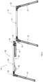
Figures 1A-1E show multiple views of a work platform for a work platform system. In these views the legs are seen in their folded and retracted positions. The hook assembly and the latch assembly are seen on the underside of the platform. The hook assembly is in its stowed position.Figure 1A is an underside view of the work platform.Figure 1B is a side view of the work platform.Figure 1C is a front view of the work platform.Figure 1D is an overhead view of the work platform.Figure 1E is a rear view of the work platform. -
Figures 2A-2C show views with the legs opened and fully extended. The legs can be extended in increments between fully retracted and fully extended. The hook assembly can be seen in the stowed position.Figure 2A is a side view of the work platform.Figure 2B is a front view of the work platform.Figure 2C is a perspective view of the work platform. -
Figure 3 shows a work platform with the leg at the hook assembly end opened and fully extended, and the leg at the latch assembly end closed and retracted. -
Figure 4 shows a work platform with both legs open and fully extended. -
Figure 5 shows an Ext WP about to be joined to a Base WP to form an extended work platform. The Ext WP is lowered vertically to engage the Base WP. -
Figure 6 shows the Ext WP joined to the Base WP. The latch assembly of the Ext WP automatically engages the hook assembly of the Base WP when the first and second work platforms are put into position. -
Figures 7A and 7B show how the latch assembly engages the hook assembly: hooks on the Ext WP latch assembly retain the crossbar of the Base WP hook assembly.Figure 7B is a underside perspective view of the work platform system.Figure 7A is a detailed view of section A offigure 7B . - In
figure 8 , the latch assembly has been unlatched so the Ext WP can be separated from the Base WP. -
Figures 9 and 10 show the Ext WP with the legs not shown for clarity.Figure 9 shows the latch assembly in the closed position.Figure 10 shows the latch assembly in the open position. -
Figure 11 shows hook assembly notches. -
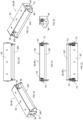
Figures 12-18 show components of the hook assembly, and the hook assembly itself in a deployed position and a stowed position.Figure 12 is a perspective view of the hook assembly.Figure 13 is a rear view of the hook assembly.Figure 14 is an overhead view of the hook assembly.Figure 15 is a side view of the hook assembly.Figure 16 is a perspective view of the hook assembly in a deployed position.Figure 17 is a perspective view of the hook assembly in the stowed position.Figure 18 is a front view of the hook assembly. -
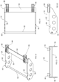
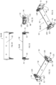
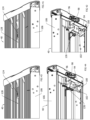
Figures 19-30 show the latch assembly in the latched position (figures 19 - 24 ) and the unlatched position (figures 25 - 30 ).Figure 19 is a right side perspective view of the latch assembly.Figure 20 is an overhead view of the latch assembly.Figure 21 is a front view of the latch assembly.Figure 22 is an underside view of the latch assembly.Figure 23 is a left side perspective view of the latch assembly.Figure 24 is a side view of the latch.Figure 25 is a right side perspective view of the latch assembly.Figure 26 is an overhead view of the latch assembly.Figure 27 is a front view of the latch assembly.Figure 28 is an underside view of the latch assembly.Figure 29 is a left side perspective view of the latch assembly.Figure 30 is a side view of the latch -
Figures 31-40 show an alternative embodiment of the latch assembly in the unlatched position (figures 31 - 35 ) and the latched position (figures 36 - 40 ).Figure 31 is a right underside view of the latch assembly.Figure 32 is a left underside view of the latch assembly.Figure 33 is a front view of the latch assembly.Figure 34 is an overhead view of the latch assembly.Figure 35 is a side of the latch assembly.Figure 36 is a right underside view of the latch assembly.Figure 37 is a left underside view of the latch assembly.Figure 38 is a front view of the latch assembly.Figure 39 is an overhead view of the latch assembly.Figure 40 is a side of the latch assembly. -
Figures 41-44 show another alternative embodiment of the latch assembly in the unlatched position (figures 41 and 42 ) and the latched position (figures 43 and 44 ). - Referring now to the drawings wherein like reference numerals refer to similar or identical parts throughout the several views, and more specifically to
figures 1A-11 thereof, there is shown awork platform system 10. Thesystem 10 comprises afirst work platform 12. Thefirst work platform 12 comprises afirst scaffold 14 having afirst end 16 and asecond end 18 and aplane 20 upon which a user can stand. Thefirst work platform 12 comprises afirst leg assembly 22 rotatably attached withbolts 24 to thefirst end 16 of thefirst scaffold 14 having afirst rail 26 and asecond rail 28 and arung 30 attached to thefirst rail 26 and thesecond rail 28. Thefirst leg assembly 22 in a folded position relative to thefirst scaffold 14 and essentially in parallel theplane 20 of thefirst scaffold 14. Thefirst work platform 12 comprises asecond leg assembly 32 rotatably attached withbolts 24 to thesecond end 18 of thefirst scaffold 14, thesecond leg assembly 32 in an open position relative to thefirst scaffold 14 and essentially perpendicular to theplane 20 of thefirst scaffold 14. Thefirst work platform 12 comprises afirst hook assembly 34 slidingly attached to thefirst scaffold 14 adjacent thefirst end 16 which slides between a use position where thefirst hook assembly 34 extends below and outward beyond thefirst scaffold 14 between thefirst rail 26 and thesecond rail 28 of thefirst leg assembly 22 and a stowed position where thefirst hook assembly 34 is retracted below thefirst scaffold 14. Thefirst work platform 12 comprises afirst latch assembly 36 attached to thefirst scaffold 14 adjacent thesecond end 18. - The
work platform system 10 comprises asecond work platform 38. Thesecond work platform 38 comprises asecond scaffold 40 having afirst end 16 and asecond end 18 and aplane 20 upon which the user can stand which is flat without objects on which the user can trip. Thesecond work platform 38 comprises athird leg assembly 42 rotatably attached withbolts 24 to thefirst end 16 of thesecond scaffold 40 having afirst rail 26 and asecond rail 28 and arung 30 attached to thefirst rail 26 and thesecond rail 28 of thethird leg assembly 42, thethird leg assembly 42 in a closed position relative to thesecond scaffold 40 and essentially in parallel to theplane 20 of thesecond scaffold 40 when thesecond scaffold 40 is attached to thefirst scaffold 14. Thesecond work platform 38 comprises afourth leg assembly 44 rotatably attached withbolts 24 to thesecond end 18 of thesecond scaffold 40, thesecond leg assembly 32 of thesecond scaffold 40 in an open position relative to thesecond scaffold 40 and essentially perpendicular to theplane 20 of thesecond scaffold 40. Thesecond work platform 38 comprises asecond hook assembly 46 slidingly attached to thesecond scaffold 40 adjacent thesecond end 18 of thesecond scaffold 40 which slides between a use position where thesecond hook assembly 46 extends below and outward beyond thesecond scaffold 40 between thefirst rail 26 and thesecond rail 28 of thefourth leg assembly 44 and a stowed position where thefirst hook assembly 34 is retracted below thefirst scaffold 14. Thesecond work platform 38 comprises a second latch assembly 48 attached to thesecond scaffold 40 adjacent thefirst end 16 of thesecond scaffold 40, thefirst work platform 12 locked to thesecond work platform 38 through thefirst hook assembly 34 engaging with the second latch assembly 48 and thefirst hook assembly 34 in the use position. - The second latch assembly 48 may have latch assembly hooks, as shown in
figures 19 - 40 . Thefirst hook assembly 34 has ahook crossbar 50 which is locked to the latch assembly by the latch assembly hooks in the use position. The second latch assembly 48 may have recesses in which thehook crossbar 50 is locked into place by the latch assembly hooks in the use position. The second latch assembly 48 may have springs engaged with the latch assembly hooks which bias the latch assembly hooks into a closed position to lock thehook crossbar 50 into place in the recesses in the use position. - The
first hook assembly 34 may have afirst hook 56 and asecond hook 58 in parallel and spaced relation with thefirst hook 56, as shown infigures 11 - 18 . Thehook crossbar 50 attached to and extending between thefirst hook 56 and thesecond hook 58. Thehook crossbar 50 may be attached adjacent afront end 60 of the first andsecond hooks first hook 56 may have atop surface 62 and afirst notch 64 disposed in thetop surface 62 of thefirst hook 56, and thesecond hook 58 has atop surface 62 and asecond notch 66 disposed in thetop surface 62 of thesecond hook 58. - The
system 10 may include afirst projection 68 and asecond projection 70 disposed adjacent thefirst end 16 of thesecond scaffold 40 and extending downward from thesecond scaffold 40, as shown infigures 8 - 11 . Thefirst projection 68 engaged with thefirst notch 64 and thesecond projection 70 engaged with thesecond notch 66 in the use position. The second latch assembly 48 may automatically engage thehook crossbar 50 when the first andsecond projections second notches first spring 53 of the springs in contact with a firstlatch assembly hook 98 of the latch assembly hooks, and asecond spring 54 of the springs in contact with a secondlatch assembly hook 100 of the latch assembly hooks. Thefirst spring 53 may be positioned about afirst rivet 72 which rotationally attaches thefirst hook 56 to thefirst bracket 94 and thesecond spring 54 may be positioned about asecond rivet 74 which rotationally attaches thesecond hook 58 to thesecond bracket 96. - The
first scaffold 14 may have afirst track 76, as shown infigure 16 and 17 , to which thefirst hook assembly 34 is engaged and slides between a deployed position, where thehook crossbar 50 extends beyond thefirst scaffold 14, and a stowed position, where thehook crossbar 50 is retracted under thefirst scaffold 14. Thefirst scaffold 14 may have asecond track 78 in parallel and spaced relation with thefirst track 76 to which thefirst hook assembly 34 is engaged and slides between the deployed position and the stowed position. The first andsecond tracks underside 80 of thefirst scaffold 14. The hook assembly may have acrossplate 82 attached adjacent to and extending between arear end 84 of the first andsecond hooks first block 86 and asecond block 88 attached to thecrossplate 82 which engage with and slide in thefirst track 76 andsecond track 78, respectively. At both ends of the first andsecond tracks second blocks second tracks - The second latch assembly 48 may have a
backing plate 92 which is attached to an underside of thesecond scaffold 40. The second latch assembly 48 may have afirst bracket 94 with afirst recess 51 of the recesses which extends perpendicularly downward from thebacking plate 92, and asecond bracket 96 with asecond recess 52 of the recesses which extends perpendicularly downward from thebacking plate 92 and in parallel and spaced relation with thefirst bracket 94. Thehook crossbar 50 disposed in the first andsecond recesses first work platform 12 is locked to thesecond work platform 38. - The second latch assembly 48 may include a first
latch assembly hook 98 of the latch assembly hooks, and a secondlatch assembly hook 100 of the latch assembly hooks. The firstlatch assembly hook 98 rotationally attached to thefirst bracket 94, and the secondlatch assembly hook 100 rotationally attached to thesecond bracket 96 such that as the first and second latch assembly hooks 98, 100 move down against thehook crossbar 50, thehook crossbar 50 cams open the first and second latch assembly hooks 98, 100 and moves into the first andsecond recesses hook crossbar 50 moves past the first and second latch assembly hooks 98, 100 and into the first andsecond recesses second work platform 38, the first and second latch assembly hooks 98, 100 of thesecond work platform 38 move back into the closed position under the action of the first andsecond springs second work platform 38 biasing the first and second latch assembly hooks 98, 100, respectively, of thesecond work platform 38 into the closed position which locks thehook crossbar 50 of thefirst work platform 12 into place in the first andsecond recesses second work platform 38. - As shown in
figures 9 and 10 , the second latch assembly 48 may include a latch crankrod 102 connected with the first and second latch assembly hooks 98, 100. The second latch assembly 48 may include afirst latch lever 104 attached to the latch crankrod 102 and to thesecond scaffold 40 which causes the first and second latch assembly hooks 98, 100 to retract to the open position when thefirst latch lever 104 is moved, so thehook crossbar 50 of thefirst work platform 12 is released from the first andsecond recesses second work platform 38 can be separated from thefirst work platform 12. Thefirst latch lever 104 may be disposed on the external surface of afirst side 106 of thesecond scaffold 40. There may be asecond latch lever 108 disposed on the external surface of a second side 110 of thesecond scaffold 40 opposing thefirst side 106. If desired the leg assemblies may be extended in height, as described inUS patent applications 11/049,453 ; and63/305,210 US patent applications 63/305,210 17/362,901 rod 102 is attached to and extends between the first and second latch levers, passing through theslot 120 in thebody 122 of each latch assembly hook, as shown infigures 31-40 . The latch crankrod 102 has a first section which is directly connected to the first latch lever and extends through thefirst side 106 of thesecond scaffold 40, a second section directly attached to and at an angle with the first section, the third section directly attached to and at an angle with the second section, a fourth section directly attached to and added an angle with the third section, and a fifth section directly attached to and at an angle with the fourth section. The fifth section is directly attached to thesecond latch lever 108 and extends through the second side 110 of thesecond scaffold 40. The third section extends directly through theslot 120 and thebody 122 of each latch assembly hook. The latch crankrod 102 is used with the latch assembly embodiment shown infigures 31-40 . The first and second work platforms each may support at least 250 lbs of load and over 500 lbs of load. The work platforms safely support a typical person standing on the work platform without buckling or failing in some way. - The
first work platform 12 comprises afirst scaffold 14 having afirst end 16 and asecond end 18 and aplane 20 upon which a user can stand. Thefirst work platform 12 comprises afirst leg assembly 22 rotatably attached withbolts 24 to thefirst end 16 of thefirst scaffold 14 having afirst rail 26 and asecond rail 28 and arung 30 attached to thefirst rail 26 and thesecond rail 28. Thefirst leg assembly 22 in a folded position relative to thefirst scaffold 14 and essentially in parallel theplane 20 of thefirst scaffold 14. Thefirst work platform 12 comprises asecond leg assembly 32 rotatably attached withbolts 24 to thesecond end 18 of thefirst scaffold 14, thesecond leg assembly 32 in an open position relative to thefirst scaffold 14 and essentially perpendicular to theplane 20 of thefirst scaffold 14. Thefirst work platform 12 comprises afirst hook assembly 34 slidingly attached to thefirst scaffold 14 adjacent thefirst end 16 which slides between a use position where thefirst hook assembly 34 extends below and outward beyond thefirst scaffold 14 between thefirst rail 26 and thesecond rail 28 of thefirst leg assembly 22 and a stowed position where thefirst hook assembly 34 is retracted below thefirst scaffold 14. Thefirst work platform 12 comprises afirst latch assembly 36 attached to thefirst scaffold 14 adjacent thesecond end 18. Thefirst hook assembly 34 having ahook crossbar 50. Thefirst work platform 12 comprises afirst latch assembly 36 having latch assembly recesses 51, 52 and latch assembly hooks 98, 100 positioned about the recesses attached to thefirst scaffold 14 adjacent thesecond end 18. - There is provided a method , not according to the invention, for using a
work platform system 10. The method comprises the steps of sliding afirst hook assembly 34 attached adjacent to afirst end 16 of afirst scaffold 14 into a use position where thefirst hook assembly 34 extends below and outward beyond thefirst scaffold 14 between afirst rail 26 and asecond rail 28 of afirst leg assembly 22 rotatably attached adjacent to thefirst end 16 of thefirst scaffold 14 from a stowed position where thefirst hook assembly 34 is retracted below thefirst scaffold 14. There is the step of placing a second latch assembly 48 attached to asecond scaffold 40 adjacent afirst end 16 of thesecond scaffold 40 on thefirst hook assembly 34 in the use position. There is the step of pushing down on thesecond scaffold 40 so the second latch assembly 48 engages with thefirst hook assembly 34 and locks thefirst work platform 12 to thesecond work platform 38 with thefirst scaffold 14 coplanar with thesecond scaffold 40 and forming a surface. - There is provided a method, not accordint to the invention, for producing a work platform. The method comprises the steps of attaching a track to an underside of a scaffold. There is the step of fitting a hook assembly to the track so the
first hook assembly 34 so the hook assembly slides along the track from a stowed position into a deployed position, where thefirst hook assembly 34 extends below and outward beyond thefirst scaffold 14 between afirst rail 26 and asecond rail 28 of afirst leg assembly 22 rotatably attached adjacent to thefirst end 16 of thefirst scaffold 14, and when thefirst hook assembly 34 is in a stowed position, thefirst hook assembly 34 is retracted below thefirst scaffold 14. There is the step of attaching a latch assembly to the bottom of the scaffold. - Additional work platforms may be added in series to the first and
second work platforms - Referring to
figure 8 , once the hook assembly is in the deployed position of thefirst work platform 12, the latch assembly hooks of the latch assembly of thesecond work platform 38 is positioned over the hook assembly crossbar. The end of thesecond work platform 38 with the latch assembly is pressed down or dropped which causes the hook assembly crossbar to cam open the latch assembly hooks and moved into the recesses of the latch brackets. As the hook assembly crossbar moves past the latch assembly hooks and into the recesses of the latch brackets, the latch assembly hooks move back into the closed position under the action of springs biasing them into the closed position and locks the hook assembly crossbar into place in the latch assembly recesses. Additionally, the projections of thesecond work platform 38 seat themselves in the hook assembly notches, to provide further stability and secure connection between the scaffolds of the first andsecond work platforms - To separate the
second work platform 38 from thefirst work platform 12, one or both of the latch levers are rotated downwards, causing the latch crankrod 102 attached to the latch lever and connected with the latch assembly hooks to retract the latch assembly hooks. With the latch assembly hooks retracted, thesecond work platform 38 is free to be lifted off of the hook assembly of thefirst work platform 12 and separated from thefirst work platform 12. -
Figures 1A-1E show multiple views of a work platform of awork platform system 10. In these views the legs are seen in their folded and retracted positions. The hook assembly and the latch assembly are seen on the underside of the platform. The hook assembly is in its stowed position. -
Figures 2A-2C show views with the legs opened and fully extended. The legs can be extended in increments between fully retracted and fully extended. The hook assembly can be seen in the stowed position. -
Figure 3 shows a work platform with the leg at the hook assembly end opened and fully extended, and the leg at the latch assembly end closed and retracted. This configuration is called an "Ext WP" configuration. -
Figure 4 shows a work platform with both legs open and fully extended. Also, the hook assembly has been slid from its stowed position to its deployed position. This configuration is called a "Base WP" configuration. Notches in the hook assembly can be seen, also infigure 11 . -
Figure 5 shows an Ext WP about to be joined to a Base WP to form an extended work platform. The Ext WP is lowered vertically to engage the Base WP. -
Figure 6 shows the Ext WP joined to the Base WP. The latch assembly of the Ext WP automatically engages the hook assembly of the Base WP when the first andsecond work platforms -
Figures 7A and 7B show how the latch assembly engages the hook assembly: hooks on the Ext WP latch assembly retain the crossbar of the Base WP hook assembly. Notice that projections on the EXT WP fit into notches in the hook assembly of the Base WP. These projections are shown infigures 9 and 10 . The notches are seen infigure 11 . - In
figure 8 , the latch assembly has been unlatched so the Ext WP can be separated from the Base WP. This unlatching is accomplished by the user pressing down on a latch lever on the side of the platform. As seen infigure 10 , there is a latch lever on both sides of the platform. -
Figures 9 and 10 show the Ext WP with the legs not shown for clarity. It can be seen that pressing down on either latch lever causes the latch crankrod 102 to rotate, which in turn rotates the latch assembly hooks to their open position. - The projections seen in
figures 9 and 10 and the notches seen infigure 11 interact to provide a visual guarantee that the Ext WP is securely engaged with the Base WP: the projections must fit into the hook assembly notches in order for the latch assembly to engage the hook assembly. If the Ext WP and the Base WP are not properly aligned and the projections are not able to seat into the notches, then the deck of the Ext WP will stick up above the deck of the Base WP. This provides a visual cue that the Ext WP is not properly latched to the hook assembly of the Base WP. -
Figures 12-18 show components of the hook assembly, and the hook assembly itself in a deployed position and a stowed position. -
Figures 19-30 show the latch assembly in the unlatched position and the latched position. -
Figures 31-40 show an alternative embodiment of the latch assembly in the unlatched position and the latched position. -
Figures 41-44 show another alternative embodiment of the latch assembly in the unlatched position and the latched position. - In an alternative embodiment of the work platform,
figures 41 and 42 show an alternative latch actuation embodiment. The legs are not shown for clarity. A slidinglatch button 124 on top of the second scaffold is connected by acable 126 to the second latch assembly on the underside of the second scaffold.Figures 41 and 42 show the latch assembly in the latched position. The latch assembly embodiment shown infigures 19-30 is used with the sliding latch button and cable. - In
figures 43 and 44 , the latch button has been slid to the unlatched position. The cable has pulled up on the second latch assembly causing the latch assembly hooks to move to the unlatched or open position. Other than the latch actuation details described here, this work platform embodiment operates in the same manner as the work platform embodiment described above. Thecable 126 extends from thelatch button 124, where it is attached, to the latch crankrod 102, where it is attached. The movement of thelatch button 124 acts similar to the latch levers, causing the latch crankrod 102 to move and thus to move the first and second latch hooks into the open position. The latch springs operate in the same way, as described above, biasing the first and second latch hooks into the closed position and thelatch button 124 back into the latched position. In this embodiment, the latch crankrod 102 is simply a single section beginning and ending at and between the first and second latch brackets, essentially corresponding to the third section of the latch crankrod 102 in the other embodiment. The slidinglatch button 124 fits into agroove 128 in the second scaffold had about a center between the first and second sides of thesecond scaffold 40 so it does not protrude above theplane 20 and possibly cause the user to trip. - The user merely presses the
second work platform 38 down onto thehook crossbar 50 of thefirst hook assembly 34 of thefirst work platform 12. The second latch assembly 48 on thesecond work platform 38 automatically engages thefirst hook assembly 34 of thefirst work platform 12. This is a very easy procedure. An additional feature is the work platform of thesystem 10 provides a visual cue to let the user know that the two work platforms are properly connected, theprojections notches - Although the invention has been described in detail in the foregoing embodiments for the purpose of illustration, it is to be understood that such detail is solely for that purpose and that variations can be made therein by those skilled in the art without departing from the scope of the following claims.
Claims (12)
- A work platform system (10) comprising:
a first work platform (12) comprising:a first end (16) and a second end (18) and a plane (20) upon which a user can stand;a first leg assembly (22) rotatably attached with bolts to the first end (16) of the first work platform (12) having a first rail (26) and a second rail (28) and a rung (30) attached to the first rail (26) and the second rail (28), wherein the first leg assembly (22) is essentially in parallel with the plane (20) of the first work platform (12) when in a folded position;a second leg assembly (32) rotatably attached with bolts to the second end (18) of the first work platform (12), wherein the second leg assembly (32) is essentially perpendicular to the plane (20) of the first work platform (12) when in an extended position;a first hook assembly (34), including a hook crossbar (50), slidingly attached to the first work platform (12) adjacent the first end (16), the first hook assembly (34) configured to slide between a use position where the first hook assembly (34) extends below and outward beyond the first work platform (12) between the first rail (26) and the second rail (28) of the first leg assembly (22) and a stowed position where the first hook assembly (34) is retracted below the first work platform (12);a first latch assembly (36) attached to the first work platform (12) adjacent the second end (18);a second work platform (38) comprising:a first end (16) and a second end (18) and a plane (20) upon which the user can stand which is flat without objects on which the user can trip;a third leg assembly (42) rotatably attached with bolts to the first end (16) of the second work platform (38) having a first rail (26) and a second rail (28) and a rung (30) attached to the first rail (26) and the second rail (28) of the third leg assembly (42), wherein the third leg assembly (42) is essentially parallel to the plane (20) of the second work platform (38) when the second work platform (38) is attached to the first work platform (12);a fourth leg assembly (44) rotatably attached with bolts to the second end (18) of the second work platform (38), wherein the second leg assembly (32) of the second work platform (38) is essentially perpendicular to the plane (20) of the second work platform (38) when in an extended position;a second hook assembly (46) slidingly attached to the second work platform (38) adjacent the second end (18) of the second work platform (38) which is configured to slide between a use position where the second hook assembly (46) extends below and outward beyond the second work platform (38) between the first rail (26) and the second rail (28) of the fourth leg assembly (44) and a stowed position where the second hook assembly (46) is retracted below the second work platform (38); anda second latch assembly (48), including latch assembly hooks (98, 100), attached to the second work platform (38) adjacent the first end (16) of the second work platform (38), the first work platform (12) locked to the second work platform (38) through the first hook assembly (34) engaging with the second latch assembly (48) and the first hook assembly (34) in the use position,wherein the latch assembly hooks (98, 100) of the second latch assembly (48) lock onto the first hook assembly (34) via the hook crossbar (50) when the second latch assembly (48) is in the use position. - The work platform system (10) of claim 1, wherein the second latch assembly (48) has recesses (51, 52) in which the hook crossbar (50) is locked into place by the latch assembly hooks (98, 100) in the use position.
- The work platform system (10) of claim 2, wherein the second latch assembly (48) has springs engaged with the latch assembly hooks (98, 100) which bias the latch assembly hooks (98, 100) into a closed position to lock the hook crossbar (50) into place in the recesses (51, 52) in the use position.
- The work platform system (10) of claim 3, wherein the first hook assembly (34) has a first hook (56) and a second hook (58) in parallel and spaced relation with the first hook (56), the hook crossbar (50) attached to and extending between the first hook (56) and the second hook (58).
- The work platform system (10) of claim 4, wherein the first hook (56) has a top surface (62) and a first notch (64) disposed in the top surface (62) of the first hook (56), and the second hook (58) has a top surface (62) and a second notch (66) disposed in the top surface (62) of the second hook (58).
- The work platform system (10) of claim 5, including a first projection (68) and a second projection (70) disposed adjacent the first end (16) of the second work platform (38) and extending downward from the second work platform (38), the first projection (68) engaged with the first notch (64) and the second projection (70) engaged with the second notch (66) in the use position.
- The work platform system (10) of any of claims 4 to 6, wherein the second latch assembly (48) includes a first spring (53) of the springs in contact with a first latch assembly (36) hook of the latch assembly hooks (98, 100), and a second spring (54) of the springs in contact with a second latch assembly (48) hook (98, 100) of the latch assembly hooks (98, 100).
- The work platform system (10) of claim 7, wherein the first work platform (12) has a first track (76) to which the first hook assembly (34) is engaged and slides between a deployed position, where the hook crossbar (50) extends beyond the first work platform (12), and a stowed position, where the hook crossbar (50) is retracted under the first work platform (12).
- The work platform system (10) of any preceding claim, wherein the second latch assembly (48) has a backing plate (92) which it is attached to an underside (80) of the second work platform (38), a first bracket (94) with a first recess of the recesses (51, 52) which extends perpendicularly downward from the backing plate (92), and a second bracket (96) with a second recess of the recesses (51, 52) which extends perpendicularly downward from the backing plate (92) and in parallel and spaced relation with the first bracket (94), the hook crossbar (50) disposed in the first and second recesses (51, 52) when the first work platform (12) is locked to the second work platform (38).
- The work platform system (10) of any preceding claim wherein the second latch assembly (48) includes a first latch assembly (36) hook of the latch assembly hooks (98, 100), and a second latch assembly (48) hook (98, 100) of the latch assembly hooks (98, 100), the first latch assembly (36) hook rotationally attached to the first bracket (94), and the second latch assembly (48) hook (98, 100) rotationally attached to the second bracket (96) such that as the first and second latch assembly (48) hooks (98, 100) move down against the hook crossbar (50), the hook crossbar (50) cams open the first and second latch assembly (48) hooks (98, 100) and moves into the first and second recesses (51, 52), as the hook crossbar (50) moves past the first and second latch assembly (48) hooks (98, 100) and into the first and second recesses (51, 52) of the second work platform (38) the first and second latch assembly (48) hooks (98, 100) of the second work platform (38) move back into the closed position under the action of the first and second springs of the second work platform (38) biasing the first and second latch assembly (48) hooks (98, 100), respectively, of the second work platform (38) into the closed position which locks the hook crossbar (50) of the first work platform (12) into place in the first and second recesses (51, 52) of the second work platform (38).
- The work platform system (10) of claim 10, wherein the second latch assembly (48) includes a latch crank rod (102) connected with the first and second latch assembly (48) hooks (98, 100), and a first latch lever (104) attached to the latch crank rod (102) and to the second work platform (38) which causes the first and second latch assembly (48) hooks (98, 100) to retract to the open position when the first latch lever (104) is moved, so the hook crossbar (50) of the first work platform (12) is released from the first and second recesses (51, 52) and the second work platform (38) can be separated from the first work platform (12).
- The work platform system (10) of claim 10, wherein the second latch assembly (48) includes a sliding latch button (124) on a top surface (62) of the second work platform (38) which is connected by a cable (126) to the second latch assembly (48) on the underside (80) of the second work platform (38), the latch button (124) causing the second latch assembly (48) to enter an open position to release the hook bar.
Priority Applications (1)
| Application Number | Priority Date | Filing Date | Title |
|---|---|---|---|
| EP24204664.7A EP4484674A3 (en) | 2021-03-02 | 2022-02-28 | Interlocking work platform system and method |
Applications Claiming Priority (1)
| Application Number | Priority Date | Filing Date | Title |
|---|---|---|---|
| US202163155722P | 2021-03-02 | 2021-03-02 |
Related Child Applications (2)
| Application Number | Title | Priority Date | Filing Date |
|---|---|---|---|
| EP24204664.7A Division EP4484674A3 (en) | 2021-03-02 | 2022-02-28 | Interlocking work platform system and method |
| EP24204664.7A Division-Into EP4484674A3 (en) | 2021-03-02 | 2022-02-28 | Interlocking work platform system and method |
Publications (2)
| Publication Number | Publication Date |
|---|---|
| EP4053357A1 EP4053357A1 (en) | 2022-09-07 |
| EP4053357B1 true EP4053357B1 (en) | 2024-12-18 |
Family
ID=80595519
Family Applications (2)
| Application Number | Title | Priority Date | Filing Date |
|---|---|---|---|
| EP22159262.9A Active EP4053357B1 (en) | 2021-03-02 | 2022-02-28 | Interlocking work platform system and method |
| EP24204664.7A Pending EP4484674A3 (en) | 2021-03-02 | 2022-02-28 | Interlocking work platform system and method |
Family Applications After (1)
| Application Number | Title | Priority Date | Filing Date |
|---|---|---|---|
| EP24204664.7A Pending EP4484674A3 (en) | 2021-03-02 | 2022-02-28 | Interlocking work platform system and method |
Country Status (6)
| Country | Link |
|---|---|
| US (2) | US12497789B2 (en) |
| EP (2) | EP4053357B1 (en) |
| CN (2) | CN117328651A (en) |
| AU (2) | AU2022201364B2 (en) |
| CA (1) | CA3150583A1 (en) |
| MX (2) | MX2022002553A (en) |
Families Citing this family (6)
| Publication number | Priority date | Publication date | Assignee | Title |
|---|---|---|---|---|
| US10801219B2 (en) | 2017-06-19 | 2020-10-13 | Werner Co. | Work scaffold and method |
| AU2020380330B2 (en) * | 2019-11-07 | 2025-10-16 | Oshkosh Corporation | Foldable rail assembly |
| EP3933164B1 (en) | 2020-07-02 | 2024-02-14 | Werner Co. | Stairway work platform and method |
| US12497789B2 (en) * | 2021-03-02 | 2025-12-16 | Werner Co. | Interlocking work platform system |
| US12392146B2 (en) * | 2022-09-20 | 2025-08-19 | Ford Global Technologies, Llc | Work surface for a vehicle |
| US20260101997A1 (en) * | 2024-10-16 | 2026-04-16 | Jinfang Yang | Foldable Step Stool |
Family Cites Families (102)
| Publication number | Priority date | Publication date | Assignee | Title |
|---|---|---|---|---|
| US3128842A (en) | 1964-04-14 | Attoknevs | ||
| US1377095A (en) | 1919-09-26 | 1921-05-03 | John D Rupp | Folding scaffold |
| US1359452A (en) | 1920-02-19 | 1920-11-16 | Howard I Walker | Scaffold |
| US1359297A (en) | 1920-05-24 | 1920-11-16 | Willis M Voss | Stepladder |
| US2186484A (en) | 1939-02-28 | 1940-01-09 | Fredrich J Gunther | Folding scaffold |
| US2446005A (en) * | 1945-10-08 | 1948-07-27 | Hartmann Fred | Collapsible scaffold |
| US2546387A (en) | 1947-03-12 | 1951-03-27 | Fredrick W Coffing | Detachable handle lock |
| US2729516A (en) * | 1952-02-13 | 1956-01-03 | Colvin Harry | Adjustable scaffold |
| DE2001416C3 (en) | 1970-01-14 | 1979-02-08 | Walter 7120 Bissingen Kuemmerlin | ladder |
| US3730465A (en) | 1971-11-12 | 1973-05-01 | A Gonzalez | Folding leg and bracket |
| EP0017957B1 (en) * | 1979-04-21 | 1982-09-15 | Gerhard Dobersch | Scaffold working platform consisting of separate planks |
| EP0125338A3 (en) * | 1983-05-06 | 1986-02-19 | Salvador Alimbau Marques | Ladder having a plurality of modules |
| ZA872922B (en) | 1986-04-24 | 1987-10-15 | University Of Queensland | Improvements in volume-selected nmr spectroscopy |
| GB2204906A (en) * | 1987-05-16 | 1988-11-23 | Andrew Ruffle | Retractable horizontal weight support |
| US5067589A (en) | 1990-07-31 | 1991-11-26 | R. D. Werner Co., Inc. | Extendable support |
| DE9217419U1 (en) * | 1992-07-23 | 1993-03-25 | Krause-Werk Gmbh & Co Kg, 6320 Alsfeld | Step plate for ladders |
| DE4447467C2 (en) * | 1994-02-19 | 1997-02-06 | Peri Gmbh | Working platform |
| DE4405289C1 (en) * | 1994-02-19 | 1995-07-13 | Peri Gmbh | Work platform for scaffolding, partic. for concrete sheathing |
| US5678653A (en) * | 1995-02-27 | 1997-10-21 | Clinch; Floyd G. | Wallboard hanging scaffolding system |
| US5746288A (en) * | 1996-08-29 | 1998-05-05 | O'neal; Diana | Walk board |
| US5676062A (en) * | 1996-09-23 | 1997-10-14 | Lloyd; John T. | Collapsible massage table |
| US5857229A (en) * | 1997-09-11 | 1999-01-12 | Magnani, Jr.; Tom J. | Playyard hinge |
| JP3044376B2 (en) * | 1997-12-04 | 2000-05-22 | 株式会社ナカオ | Scaffolding platform for telescopic work and telescopic top plate |
| US6471003B2 (en) * | 2001-01-19 | 2002-10-29 | Steven J. Wyse | Utility scaffolding having safety features |
| US20020189902A1 (en) | 2001-06-13 | 2002-12-19 | Nelson John R. | Protective carrying attachment for ladders |
| JP3917040B2 (en) | 2002-08-07 | 2007-05-23 | ジーオーピー株式会社 | Temporary worktable |
| US6892860B2 (en) * | 2003-05-28 | 2005-05-17 | Cosco Management, Inc. | Scaffold with leg lock |
| US6902034B2 (en) * | 2003-05-28 | 2005-06-07 | Cosco Management, Inc. | Apparatus with utility tray mounted to scaffold |
| GB0404262D0 (en) | 2004-02-26 | 2004-03-31 | Metsec Plc | Scaffolding plank |
| KR100714992B1 (en) * | 2004-12-22 | 2007-05-09 | 임정환 | Folding work bench |
| KR100714993B1 (en) | 2004-12-22 | 2007-05-09 | 임정환 | Folding work bench |
| US8042653B2 (en) * | 2005-02-02 | 2011-10-25 | Werner Co. | Adjustable work platform |
| FR2890677B1 (en) | 2005-09-12 | 2007-10-19 | Comabi Snc | INDIVIDUAL PLATFORM OF WORK |
| US20070074932A1 (en) | 2005-09-19 | 2007-04-05 | Robert Mutscheller | Padding device for use with ladders |
| EP1788167A1 (en) * | 2005-11-18 | 2007-05-23 | Telesteps AB | Collapsible platform |
| WO2007132148A2 (en) | 2006-05-04 | 2007-11-22 | Access Products Limited | Scaffolding |
| DE102007007059A1 (en) | 2007-02-08 | 2008-08-21 | Krause-Werk Gmbh & Co. Kg | Length-adjustable work platform |
| FR2914338B1 (en) | 2007-03-30 | 2009-05-08 | Duarib Soc Par Actions Simplif | LEG FOR SUPPORTING OR STABILIZING STRUCTURE AND STRUCTURE EQUIPPED WITH SUCH LEG |
| KR100855365B1 (en) * | 2007-05-04 | 2008-09-04 | 이영학 | bench |
| KR20090000735U (en) * | 2007-07-20 | 2009-01-23 | 김춘대 | Height adjustable workbench and height adjuster |
| KR20090007010U (en) * | 2008-01-07 | 2009-07-13 | 윤용길 | Scaffolding legs |
| KR20090007282U (en) * | 2008-01-15 | 2009-07-20 | 김만섭 | Worktable and detachable height adjuster. |
| KR100977715B1 (en) * | 2008-02-14 | 2010-08-24 | 유수원 | bench |
| KR20090088156A (en) * | 2008-02-14 | 2009-08-19 | 유수원 | Leg member folding device of work bench |
| KR200448932Y1 (en) * | 2008-03-17 | 2010-06-08 | 김진희 | Uma ladder |
| US8186480B1 (en) * | 2008-06-23 | 2012-05-29 | Yoakum Jr Ruben | Modular scaffold ladder and associated method |
| US20100071996A1 (en) * | 2008-09-24 | 2010-03-25 | Wen-Hung Huang | Collapsible platform ladder |
| KR20100010258U (en) * | 2009-04-10 | 2010-10-20 | 김진희 | Structure to prevent slip of a top plate for folding work platforms |
| US8997930B2 (en) * | 2009-05-05 | 2015-04-07 | Wing Enterprises, Inc. | Ladders, ladder components, ladder accessories, ladder systems and related methods |
| US8381873B2 (en) * | 2009-07-28 | 2013-02-26 | Affinity Tool Works | Ladder and support stand |
| FR2975116B1 (en) | 2011-05-12 | 2013-05-03 | Zhuhai Quan Da Industry & Commerce | FOLDING SCAFFOLD |
| AU2014320099B2 (en) | 2013-09-16 | 2018-07-05 | A-Fax Limited | Structure protector |
| US20160138338A1 (en) * | 2014-11-19 | 2016-05-19 | Garlock Safety Systems Inc. | Bi-Level Work Platform for ISO Tanks |
| USD776826S1 (en) * | 2015-08-13 | 2017-01-17 | Tricam Industries, Inc. | Work platform |
| CN105201192B (en) | 2015-10-19 | 2017-03-29 | 金陵科技学院 | A kind of interior decoration scaffold |
| KR20170002456U (en) * | 2015-12-29 | 2017-07-07 | 임한솔 | Multifunctional ladder |
| US10435894B2 (en) | 2016-03-22 | 2019-10-08 | Werner Co. | Scaffold with latch assembly and method |
| US10738487B2 (en) * | 2016-03-22 | 2020-08-11 | Werner Co. | Apparatus having a handle on which a user stands, and method |
| USD895844S1 (en) * | 2016-03-22 | 2020-09-08 | Werner Co. | Work platform |
| US10815680B2 (en) * | 2016-03-22 | 2020-10-27 | Werner Co. | Apparatus having a handle on which a user stands, and method |
| US10858848B2 (en) * | 2016-03-22 | 2020-12-08 | Werner Co. | Work platform and method |
| USD895845S1 (en) * | 2016-03-22 | 2020-09-08 | Werner Co. | Work platform |
| US11131103B2 (en) * | 2016-03-22 | 2021-09-28 | Werner Co. | Assembly, plank adapter for a work stand and method |
| US20170334059A1 (en) * | 2016-05-23 | 2017-11-23 | Gary Moffat | Convertible Elongated Stepping Bench |
| CN106184139B (en) * | 2016-08-26 | 2018-10-26 | 苏州飞华铝制工业有限公司 | A kind of bullet lock fixed pattern operation console |
| CN106193564B (en) * | 2016-08-30 | 2018-08-14 | 苏州飞华铝制工业有限公司 | A kind of locking plate pendulum lock fixed pattern operation console |
| US10035255B2 (en) * | 2016-09-28 | 2018-07-31 | Owen Cindric | Portable workbench assembly |
| US10145128B2 (en) * | 2016-12-16 | 2018-12-04 | Werner Co. | Interlocking work platform system and method |
| DE202017100661U1 (en) * | 2017-02-08 | 2018-04-20 | Hailo-Werk Rudolf Loh Gmbh & Co. Kg | Device for setting up a ladder or step on a staircase |
| AU2018201577A1 (en) | 2017-03-16 | 2018-10-04 | Werner Co. | Work platform and method |
| KR20180112396A (en) * | 2017-04-03 | 2018-10-12 | 주식회사대동엔지니어링 | Ladder for work |
| JP6851883B2 (en) | 2017-04-04 | 2021-03-31 | アルインコ株式会社 | Folding workbench |
| CN106996187B (en) * | 2017-05-23 | 2023-10-24 | 佛山维可斯脚手架有限公司 | Scaffolding working platform and processing equipment |
| US10801219B2 (en) * | 2017-06-19 | 2020-10-13 | Werner Co. | Work scaffold and method |
| CN207436473U (en) * | 2017-08-04 | 2018-06-01 | 苏州飞华铝制工业有限公司 | The unlocking structure of workbench cleat stanchion |
| CN108086665B (en) * | 2017-11-24 | 2023-10-13 | 重庆今心实业有限公司 | Folding portable mobile operation platform |
| US20190226217A1 (en) * | 2018-01-24 | 2019-07-25 | Tricam Industries, Inc. | Work platform |
| CN208534971U (en) * | 2018-06-21 | 2019-02-22 | 江苏宙际杰智能科技股份有限公司 | Fold locking mechanisms for step stool |
| JP2020002651A (en) | 2018-06-28 | 2020-01-09 | 大和ハウス工業株式会社 | Workbench unit |
| US10837229B2 (en) * | 2018-08-21 | 2020-11-17 | Hyundai Aluminum Vina Shareholding Company | Ladder with a guardrail |
| CN209228004U (en) * | 2018-10-15 | 2019-08-09 | 广东电网有限责任公司 | A mobile operating platform |
| FR3096381B1 (en) * | 2019-05-24 | 2022-03-25 | Cdh Group | TOOLLESS PLATFORM ASSEMBLY SYSTEM |
| US20210087882A1 (en) | 2019-09-25 | 2021-03-25 | David Wayne Waddell | Attachable Pad Device |
| CN110556076B (en) | 2019-09-29 | 2020-12-08 | 福州京东方光电科技有限公司 | Pixel circuit, driving method and display device |
| KR200493337Y1 (en) * | 2019-10-28 | 2021-03-16 | 주식회사 쿨런바이크 | Anti-shake device an ladder with the same |
| KR200494805Y1 (en) * | 2019-10-28 | 2021-12-30 | 주식회사 쿨런바이크 | Function ladder |
| CN212345738U (en) * | 2020-01-20 | 2021-01-15 | 革新(厦门)运动器材有限公司 | Folding structure |
| CN111608375A (en) * | 2020-06-01 | 2020-09-01 | 界首市天瓴建筑工程有限公司 | Assembled auxiliary platform for building wall maintenance |
| EP3933164B1 (en) * | 2020-07-02 | 2024-02-14 | Werner Co. | Stairway work platform and method |
| CN111734101A (en) * | 2020-07-14 | 2020-10-02 | 苏州莱恩精工合金股份有限公司 | folding table |
| CN214382300U (en) * | 2020-07-23 | 2021-10-12 | 厦门新技术集成有限公司 | Folding stool |
| CN112145065A (en) * | 2020-08-14 | 2020-12-29 | 河北省金具电力有限公司 | Folding insulating ladder and processing technology and using method thereof |
| KR20220043608A (en) * | 2020-09-29 | 2022-04-05 | 삼성중공업 주식회사 | Moving worktable |
| CN112299241A (en) * | 2020-10-06 | 2021-02-02 | 国家电网有限公司 | Folding lifting machine for construction operation |
| CN112282332B (en) * | 2020-10-28 | 2022-05-06 | 山东城邦建设有限公司 | Supplementary ladder of domestic construction with table surface |
| US20220178153A1 (en) * | 2020-12-04 | 2022-06-09 | Steve Woodward | Work Platform and Method |
| US12497789B2 (en) * | 2021-03-02 | 2025-12-16 | Werner Co. | Interlocking work platform system |
| US20230014482A1 (en) * | 2021-07-13 | 2023-01-19 | Werner Co. | Work Platform and Method |
| US12565779B2 (en) * | 2021-10-28 | 2026-03-03 | Werner Co. | Work platform and method |
| NL2029736B1 (en) * | 2021-11-12 | 2023-06-08 | Lampe Holding Bv | Assembly comprising a folding ladder and a platform |
| USD1047872S1 (en) * | 2022-01-14 | 2024-10-22 | Tianjin Jinmao Houseware Products Co., Ltd | Platform ladder |
| AU2023213818A1 (en) | 2022-01-31 | 2024-08-08 | Werner Co. | Ladders, ladder accessories, components thereof, and lock assemblies for use therewith |
-
2022
- 2022-02-25 US US17/681,076 patent/US12497789B2/en active Active
- 2022-02-28 EP EP22159262.9A patent/EP4053357B1/en active Active
- 2022-02-28 EP EP24204664.7A patent/EP4484674A3/en active Pending
- 2022-02-28 AU AU2022201364A patent/AU2022201364B2/en active Active
- 2022-03-01 CN CN202311335259.7A patent/CN117328651A/en active Pending
- 2022-03-01 MX MX2022002553A patent/MX2022002553A/en unknown
- 2022-03-01 MX MX2026000246A patent/MX2026000246A/en unknown
- 2022-03-01 CN CN202210194133.1A patent/CN114991442A/en active Pending
- 2022-03-01 CA CA3150583A patent/CA3150583A1/en active Pending
-
2024
- 2024-05-30 AU AU2024203625A patent/AU2024203625B2/en active Active
-
2025
- 2025-01-14 US US19/020,584 patent/US20250154779A1/en active Pending
Also Published As
| Publication number | Publication date |
|---|---|
| US20250154779A1 (en) | 2025-05-15 |
| EP4484674A3 (en) | 2025-02-19 |
| MX2026000246A (en) | 2026-03-02 |
| EP4053357A1 (en) | 2022-09-07 |
| US20220282501A1 (en) | 2022-09-08 |
| CA3150583A1 (en) | 2022-09-02 |
| CN114991442A (en) | 2022-09-02 |
| MX2022002553A (en) | 2022-09-05 |
| AU2024203625A1 (en) | 2024-06-20 |
| AU2022201364A1 (en) | 2022-09-22 |
| CN117328651A (en) | 2024-01-02 |
| US12497789B2 (en) | 2025-12-16 |
| AU2022201364B2 (en) | 2024-03-28 |
| EP4484674A2 (en) | 2025-01-01 |
| AU2024203625B2 (en) | 2026-06-04 |
Similar Documents
| Publication | Publication Date | Title |
|---|---|---|
| EP4484674A2 (en) | Interlocking work platform system and method | |
| US10233693B2 (en) | Adjustable ladders, ladder components and related methods | |
| US12435567B2 (en) | Extension ladder, ladder components and related methods | |
| CN109154172B (en) | Ladders, ladder hinges, and related methods | |
| EP3423664B1 (en) | Adjustment mechanisms, ladders incorporating same and related methods | |
| EP2754849B1 (en) | Stepladder with latch stud and method | |
| US12077970B2 (en) | Work platform and method | |
| US20230374858A1 (en) | Adjustable ladders, ladder components and related methods | |
| US8028805B2 (en) | Access ladder with plungers | |
| US12398595B2 (en) | Climbing product having an extendable section lock assembly | |
| NZ785971A (en) | Interlocking Work Platform System and Method | |
| CN219158344U (en) | Assembly comprising a folding ladder and a platform | |
| JP3061770B2 (en) | Telescopic leg fixing device | |
| JP2006152593A (en) | Portable worktable | |
| KR0180981B1 (en) | Heavy equipment ladder | |
| JPH0735119Y2 (en) | Telescopic support lock device for ladders, etc. | |
| JP2003239527A5 (en) | ||
| JPH10196259A (en) | Fall prevention stepladder with safety device | |
| TH15310A (en) | A foldable ladder frame that can be opened in two directions. |
Legal Events
| Date | Code | Title | Description |
|---|---|---|---|
| PUAI | Public reference made under article 153(3) epc to a published international application that has entered the european phase |
Free format text: ORIGINAL CODE: 0009012 |
|
| STAA | Information on the status of an ep patent application or granted ep patent |
Free format text: STATUS: THE APPLICATION HAS BEEN PUBLISHED |
|
| AK | Designated contracting states |
Kind code of ref document: A1 Designated state(s): AL AT BE BG CH CY CZ DE DK EE ES FI FR GB GR HR HU IE IS IT LI LT LU LV MC MK MT NL NO PL PT RO RS SE SI SK SM TR |
|
| STAA | Information on the status of an ep patent application or granted ep patent |
Free format text: STATUS: REQUEST FOR EXAMINATION WAS MADE |
|
| 17P | Request for examination filed |
Effective date: 20230307 |
|
| RBV | Designated contracting states (corrected) |
Designated state(s): AL AT BE BG CH CY CZ DE DK EE ES FI FR GB GR HR HU IE IS IT LI LT LU LV MC MK MT NL NO PL PT RO RS SE SI SK SM TR |
|
| GRAP | Despatch of communication of intention to grant a patent |
Free format text: ORIGINAL CODE: EPIDOSNIGR1 |
|
| STAA | Information on the status of an ep patent application or granted ep patent |
Free format text: STATUS: GRANT OF PATENT IS INTENDED |
|
| INTG | Intention to grant announced |
Effective date: 20240716 |
|
| RAP3 | Party data changed (applicant data changed or rights of an application transferred) |
Owner name: WERNER CO. |
|
| RIN1 | Information on inventor provided before grant (corrected) |
Inventor name: ZHU, LING Inventor name: HE, LIANG Inventor name: CHEN, FANG |
|
| GRAJ | Information related to disapproval of communication of intention to grant by the applicant or resumption of examination proceedings by the epo deleted |
Free format text: ORIGINAL CODE: EPIDOSDIGR1 |
|
| STAA | Information on the status of an ep patent application or granted ep patent |
Free format text: STATUS: REQUEST FOR EXAMINATION WAS MADE |
|
| GRAP | Despatch of communication of intention to grant a patent |
Free format text: ORIGINAL CODE: EPIDOSNIGR1 |
|
| STAA | Information on the status of an ep patent application or granted ep patent |
Free format text: STATUS: GRANT OF PATENT IS INTENDED |
|
| INTC | Intention to grant announced (deleted) | ||
| GRAS | Grant fee paid |
Free format text: ORIGINAL CODE: EPIDOSNIGR3 |
|
| GRAA | (expected) grant |
Free format text: ORIGINAL CODE: 0009210 |
|
| STAA | Information on the status of an ep patent application or granted ep patent |
Free format text: STATUS: THE PATENT HAS BEEN GRANTED |
|
| INTG | Intention to grant announced |
Effective date: 20241028 |
|
| AK | Designated contracting states |
Kind code of ref document: B1 Designated state(s): AL AT BE BG CH CY CZ DE DK EE ES FI FR GB GR HR HU IE IS IT LI LT LU LV MC MK MT NL NO PL PT RO RS SE SI SK SM TR |
|
| REG | Reference to a national code |
Ref country code: CH Ref legal event code: EP |
|
| REG | Reference to a national code |
Ref country code: DE Ref legal event code: R096 Ref document number: 602022008711 Country of ref document: DE |
|
| REG | Reference to a national code |
Ref country code: IE Ref legal event code: FG4D |
|
| REG | Reference to a national code |
Ref country code: LT Ref legal event code: MG9D |
|
| PG25 | Lapsed in a contracting state [announced via postgrant information from national office to epo] |
Ref country code: HR Free format text: LAPSE BECAUSE OF FAILURE TO SUBMIT A TRANSLATION OF THE DESCRIPTION OR TO PAY THE FEE WITHIN THE PRESCRIBED TIME-LIMIT Effective date: 20241218 |
|
| PG25 | Lapsed in a contracting state [announced via postgrant information from national office to epo] |
Ref country code: FI Free format text: LAPSE BECAUSE OF FAILURE TO SUBMIT A TRANSLATION OF THE DESCRIPTION OR TO PAY THE FEE WITHIN THE PRESCRIBED TIME-LIMIT Effective date: 20241218 |
|
| PG25 | Lapsed in a contracting state [announced via postgrant information from national office to epo] |
Ref country code: BG Free format text: LAPSE BECAUSE OF FAILURE TO SUBMIT A TRANSLATION OF THE DESCRIPTION OR TO PAY THE FEE WITHIN THE PRESCRIBED TIME-LIMIT Effective date: 20241218 |
|
| PG25 | Lapsed in a contracting state [announced via postgrant information from national office to epo] |
Ref country code: NO Free format text: LAPSE BECAUSE OF FAILURE TO SUBMIT A TRANSLATION OF THE DESCRIPTION OR TO PAY THE FEE WITHIN THE PRESCRIBED TIME-LIMIT Effective date: 20250318 |
|
| REG | Reference to a national code |
Ref country code: NL Ref legal event code: MP Effective date: 20241218 |
|
| PG25 | Lapsed in a contracting state [announced via postgrant information from national office to epo] |
Ref country code: LV Free format text: LAPSE BECAUSE OF FAILURE TO SUBMIT A TRANSLATION OF THE DESCRIPTION OR TO PAY THE FEE WITHIN THE PRESCRIBED TIME-LIMIT Effective date: 20241218 Ref country code: GR Free format text: LAPSE BECAUSE OF FAILURE TO SUBMIT A TRANSLATION OF THE DESCRIPTION OR TO PAY THE FEE WITHIN THE PRESCRIBED TIME-LIMIT Effective date: 20250319 |
|
| PG25 | Lapsed in a contracting state [announced via postgrant information from national office to epo] |
Ref country code: RS Free format text: LAPSE BECAUSE OF FAILURE TO SUBMIT A TRANSLATION OF THE DESCRIPTION OR TO PAY THE FEE WITHIN THE PRESCRIBED TIME-LIMIT Effective date: 20250318 |
|
| PG25 | Lapsed in a contracting state [announced via postgrant information from national office to epo] |
Ref country code: NL Free format text: LAPSE BECAUSE OF FAILURE TO SUBMIT A TRANSLATION OF THE DESCRIPTION OR TO PAY THE FEE WITHIN THE PRESCRIBED TIME-LIMIT Effective date: 20241218 |
|
| REG | Reference to a national code |
Ref country code: AT Ref legal event code: MK05 Ref document number: 1752348 Country of ref document: AT Kind code of ref document: T Effective date: 20241218 |
|
| PG25 | Lapsed in a contracting state [announced via postgrant information from national office to epo] |
Ref country code: SM Free format text: LAPSE BECAUSE OF FAILURE TO SUBMIT A TRANSLATION OF THE DESCRIPTION OR TO PAY THE FEE WITHIN THE PRESCRIBED TIME-LIMIT Effective date: 20241218 |
|
| PG25 | Lapsed in a contracting state [announced via postgrant information from national office to epo] |
Ref country code: PL Free format text: LAPSE BECAUSE OF FAILURE TO SUBMIT A TRANSLATION OF THE DESCRIPTION OR TO PAY THE FEE WITHIN THE PRESCRIBED TIME-LIMIT Effective date: 20241218 |
|
| PG25 | Lapsed in a contracting state [announced via postgrant information from national office to epo] |
Ref country code: ES Free format text: LAPSE BECAUSE OF FAILURE TO SUBMIT A TRANSLATION OF THE DESCRIPTION OR TO PAY THE FEE WITHIN THE PRESCRIBED TIME-LIMIT Effective date: 20241218 |
|
| PG25 | Lapsed in a contracting state [announced via postgrant information from national office to epo] |
Ref country code: IS Free format text: LAPSE BECAUSE OF FAILURE TO SUBMIT A TRANSLATION OF THE DESCRIPTION OR TO PAY THE FEE WITHIN THE PRESCRIBED TIME-LIMIT Effective date: 20250418 |
|
| PG25 | Lapsed in a contracting state [announced via postgrant information from national office to epo] |
Ref country code: PT Free format text: LAPSE BECAUSE OF FAILURE TO SUBMIT A TRANSLATION OF THE DESCRIPTION OR TO PAY THE FEE WITHIN THE PRESCRIBED TIME-LIMIT Effective date: 20250421 |
|
| PG25 | Lapsed in a contracting state [announced via postgrant information from national office to epo] |
Ref country code: EE Free format text: LAPSE BECAUSE OF FAILURE TO SUBMIT A TRANSLATION OF THE DESCRIPTION OR TO PAY THE FEE WITHIN THE PRESCRIBED TIME-LIMIT Effective date: 20241218 |
|
| PG25 | Lapsed in a contracting state [announced via postgrant information from national office to epo] |
Ref country code: AT Free format text: LAPSE BECAUSE OF FAILURE TO SUBMIT A TRANSLATION OF THE DESCRIPTION OR TO PAY THE FEE WITHIN THE PRESCRIBED TIME-LIMIT Effective date: 20241218 Ref country code: RO Free format text: LAPSE BECAUSE OF FAILURE TO SUBMIT A TRANSLATION OF THE DESCRIPTION OR TO PAY THE FEE WITHIN THE PRESCRIBED TIME-LIMIT Effective date: 20241218 |
|
| PG25 | Lapsed in a contracting state [announced via postgrant information from national office to epo] |
Ref country code: SK Free format text: LAPSE BECAUSE OF FAILURE TO SUBMIT A TRANSLATION OF THE DESCRIPTION OR TO PAY THE FEE WITHIN THE PRESCRIBED TIME-LIMIT Effective date: 20241218 |
|
| PG25 | Lapsed in a contracting state [announced via postgrant information from national office to epo] |
Ref country code: CZ Free format text: LAPSE BECAUSE OF FAILURE TO SUBMIT A TRANSLATION OF THE DESCRIPTION OR TO PAY THE FEE WITHIN THE PRESCRIBED TIME-LIMIT Effective date: 20241218 |
|
| PG25 | Lapsed in a contracting state [announced via postgrant information from national office to epo] |
Ref country code: IT Free format text: LAPSE BECAUSE OF FAILURE TO SUBMIT A TRANSLATION OF THE DESCRIPTION OR TO PAY THE FEE WITHIN THE PRESCRIBED TIME-LIMIT Effective date: 20241218 |
|
| PG25 | Lapsed in a contracting state [announced via postgrant information from national office to epo] |
Ref country code: SE Free format text: LAPSE BECAUSE OF FAILURE TO SUBMIT A TRANSLATION OF THE DESCRIPTION OR TO PAY THE FEE WITHIN THE PRESCRIBED TIME-LIMIT Effective date: 20241218 |
|
| PG25 | Lapsed in a contracting state [announced via postgrant information from national office to epo] |
Ref country code: MC Free format text: LAPSE BECAUSE OF FAILURE TO SUBMIT A TRANSLATION OF THE DESCRIPTION OR TO PAY THE FEE WITHIN THE PRESCRIBED TIME-LIMIT Effective date: 20241218 |
|
| REG | Reference to a national code |
Ref country code: DE Ref legal event code: R097 Ref document number: 602022008711 Country of ref document: DE |
|
| REG | Reference to a national code |
Ref country code: CH Ref legal event code: PL |
|
| PG25 | Lapsed in a contracting state [announced via postgrant information from national office to epo] |
Ref country code: DK Free format text: LAPSE BECAUSE OF FAILURE TO SUBMIT A TRANSLATION OF THE DESCRIPTION OR TO PAY THE FEE WITHIN THE PRESCRIBED TIME-LIMIT Effective date: 20241218 |
|
| PG25 | Lapsed in a contracting state [announced via postgrant information from national office to epo] |
Ref country code: LU Free format text: LAPSE BECAUSE OF NON-PAYMENT OF DUE FEES Effective date: 20250228 |
|
| PG25 | Lapsed in a contracting state [announced via postgrant information from national office to epo] |
Ref country code: CH Free format text: LAPSE BECAUSE OF NON-PAYMENT OF DUE FEES Effective date: 20250228 |
|
| PLBE | No opposition filed within time limit |
Free format text: ORIGINAL CODE: 0009261 |
|
| STAA | Information on the status of an ep patent application or granted ep patent |
Free format text: STATUS: NO OPPOSITION FILED WITHIN TIME LIMIT |
|
| 26N | No opposition filed |
Effective date: 20250919 |
|
| REG | Reference to a national code |
Ref country code: BE Ref legal event code: MM Effective date: 20250228 |
|
| PG25 | Lapsed in a contracting state [announced via postgrant information from national office to epo] |
Ref country code: FR Free format text: LAPSE BECAUSE OF NON-PAYMENT OF DUE FEES Effective date: 20250228 |
|
| PG25 | Lapsed in a contracting state [announced via postgrant information from national office to epo] |
Ref country code: BE Free format text: LAPSE BECAUSE OF NON-PAYMENT OF DUE FEES Effective date: 20250228 |
|
| PG25 | Lapsed in a contracting state [announced via postgrant information from national office to epo] |
Ref country code: IE Free format text: LAPSE BECAUSE OF NON-PAYMENT OF DUE FEES Effective date: 20250228 |
|
| PGFP | Annual fee paid to national office [announced via postgrant information from national office to epo] |
Ref country code: DE Payment date: 20260102 Year of fee payment: 5 |
|
| PG25 | Lapsed in a contracting state [announced via postgrant information from national office to epo] |
Ref country code: CY Free format text: LAPSE BECAUSE OF FAILURE TO SUBMIT A TRANSLATION OF THE DESCRIPTION OR TO PAY THE FEE WITHIN THE PRESCRIBED TIME-LIMIT Effective date: 20241218 |
|
| PG25 | Lapsed in a contracting state [announced via postgrant information from national office to epo] |
Ref country code: LT Free format text: LAPSE BECAUSE OF FAILURE TO SUBMIT A TRANSLATION OF THE DESCRIPTION OR TO PAY THE FEE WITHIN THE PRESCRIBED TIME-LIMIT Effective date: 20241218 |
|
| PG25 | Lapsed in a contracting state [announced via postgrant information from national office to epo] |
Ref country code: TR Free format text: LAPSE BECAUSE OF FAILURE TO SUBMIT A TRANSLATION OF THE DESCRIPTION OR TO PAY THE FEE WITHIN THE PRESCRIBED TIME-LIMIT Effective date: 20241218 |