EP4053057A1 - Rewinding system - Google Patents
Rewinding system Download PDFInfo
- Publication number
- EP4053057A1 EP4053057A1 EP20914269.4A EP20914269A EP4053057A1 EP 4053057 A1 EP4053057 A1 EP 4053057A1 EP 20914269 A EP20914269 A EP 20914269A EP 4053057 A1 EP4053057 A1 EP 4053057A1
- Authority
- EP
- European Patent Office
- Prior art keywords
- mounting member
- thin
- film tape
- rewinding
- loading
- Prior art date
- Legal status (The legal status is an assumption and is not a legal conclusion. Google has not performed a legal analysis and makes no representation as to the accuracy of the status listed.)
- Granted
Links
Images






Classifications
-
- B—PERFORMING OPERATIONS; TRANSPORTING
- B65—CONVEYING; PACKING; STORING; HANDLING THIN OR FILAMENTARY MATERIAL
- B65H—HANDLING THIN OR FILAMENTARY MATERIAL, e.g. SHEETS, WEBS, CABLES
- B65H19/00—Changing the web roll
- B65H19/10—Changing the web roll in unwinding mechanisms or in connection with unwinding operations
- B65H19/18—Attaching, e.g. pasting, the replacement web to the expiring web
- B65H19/1857—Support arrangement of web rolls
- B65H19/1868—The roll support being of the turret type
-
- B—PERFORMING OPERATIONS; TRANSPORTING
- B65—CONVEYING; PACKING; STORING; HANDLING THIN OR FILAMENTARY MATERIAL
- B65H—HANDLING THIN OR FILAMENTARY MATERIAL, e.g. SHEETS, WEBS, CABLES
- B65H19/00—Changing the web roll
- B65H19/22—Changing the web roll in winding mechanisms or in connection with winding operations
- B65H19/2207—Changing the web roll in winding mechanisms or in connection with winding operations the web roll being driven by a winding mechanism of the centre or core drive type
- B65H19/2215—Turret-type with two roll supports
-
- B—PERFORMING OPERATIONS; TRANSPORTING
- B65—CONVEYING; PACKING; STORING; HANDLING THIN OR FILAMENTARY MATERIAL
- B65H—HANDLING THIN OR FILAMENTARY MATERIAL, e.g. SHEETS, WEBS, CABLES
- B65H18/00—Winding webs
- B65H18/08—Web-winding mechanisms
- B65H18/10—Mechanisms in which power is applied to web-roll spindle
- B65H18/106—Mechanisms in which power is applied to web-roll spindle for several juxtaposed strips
-
- B—PERFORMING OPERATIONS; TRANSPORTING
- B65—CONVEYING; PACKING; STORING; HANDLING THIN OR FILAMENTARY MATERIAL
- B65H—HANDLING THIN OR FILAMENTARY MATERIAL, e.g. SHEETS, WEBS, CABLES
- B65H19/00—Changing the web roll
- B65H19/10—Changing the web roll in unwinding mechanisms or in connection with unwinding operations
- B65H19/12—Lifting, transporting, or inserting the web roll; Removing empty core
-
- B—PERFORMING OPERATIONS; TRANSPORTING
- B65—CONVEYING; PACKING; STORING; HANDLING THIN OR FILAMENTARY MATERIAL
- B65H—HANDLING THIN OR FILAMENTARY MATERIAL, e.g. SHEETS, WEBS, CABLES
- B65H19/00—Changing the web roll
- B65H19/10—Changing the web roll in unwinding mechanisms or in connection with unwinding operations
- B65H19/20—Cutting-off the expiring web
-
- B—PERFORMING OPERATIONS; TRANSPORTING
- B65—CONVEYING; PACKING; STORING; HANDLING THIN OR FILAMENTARY MATERIAL
- B65H—HANDLING THIN OR FILAMENTARY MATERIAL, e.g. SHEETS, WEBS, CABLES
- B65H19/00—Changing the web roll
- B65H19/22—Changing the web roll in winding mechanisms or in connection with winding operations
- B65H19/26—Cutting-off the web running to the wound web roll
-
- B—PERFORMING OPERATIONS; TRANSPORTING
- B65—CONVEYING; PACKING; STORING; HANDLING THIN OR FILAMENTARY MATERIAL
- B65H—HANDLING THIN OR FILAMENTARY MATERIAL, e.g. SHEETS, WEBS, CABLES
- B65H2301/00—Handling processes for sheets or webs
- B65H2301/40—Type of handling process
- B65H2301/41—Winding, unwinding
- B65H2301/413—Supporting web roll
- B65H2301/4136—Mounting arrangements not otherwise provided for
- B65H2301/41362—Mounting arrangements not otherwise provided for one of the supports for the roller axis being movable as auxiliary bearing
-
- B—PERFORMING OPERATIONS; TRANSPORTING
- B65—CONVEYING; PACKING; STORING; HANDLING THIN OR FILAMENTARY MATERIAL
- B65H—HANDLING THIN OR FILAMENTARY MATERIAL, e.g. SHEETS, WEBS, CABLES
- B65H2406/00—Means using fluid
- B65H2406/30—Suction means
-
- B—PERFORMING OPERATIONS; TRANSPORTING
- B65—CONVEYING; PACKING; STORING; HANDLING THIN OR FILAMENTARY MATERIAL
- B65H—HANDLING THIN OR FILAMENTARY MATERIAL, e.g. SHEETS, WEBS, CABLES
- B65H2701/00—Handled material; Storage means
- B65H2701/10—Handled articles or webs
- B65H2701/11—Dimensional aspect of article or web
- B65H2701/113—Size
- B65H2701/1133—Size of webs
- B65H2701/11332—Size of webs strip, tape, narrow web
-
- B—PERFORMING OPERATIONS; TRANSPORTING
- B65—CONVEYING; PACKING; STORING; HANDLING THIN OR FILAMENTARY MATERIAL
- B65H—HANDLING THIN OR FILAMENTARY MATERIAL, e.g. SHEETS, WEBS, CABLES
- B65H2701/00—Handled material; Storage means
- B65H2701/30—Handled filamentary material
- B65H2701/37—Tapes
Definitions
- the present disclosure relates to a rewinding system having improved process efficiency.
- thin-film tapes for various purposes, such as adhesion, insulation, and electrical connection between components in each electronic device are being used.
- Thin-film tapes being manufactured are manufactured in a primary form of being wound on a roll.
- each electronic device needs to be processed to the size and length required according to the manufacturing process thereof, and a secondary processing for winding the thin-film tapes on a new roll is required.
- a rewinding apparatus for newly winding a manufactured thin-film tape according to the needs of users and processes is used.
- the manufacturing efficiency of the entire process, including secondary processing varies according to the process efficiency of a rewinding apparatus, and thus the efficiency of a rewinding apparatus for newly winding a manufactured thin-film tape is quite important the efficiency of a rewinding apparatus for newly winding a manufactured thin-film tape is quite important.
- the purpose of the present disclosure is to provide a rewinding system having improved process efficiency.
- the present disclosure for achieving the above purpose provides a rewinding system, comprising: a rewinding apparatus for winding a manufactured thin-film tape on a re-winding roll; a loading apparatus for loading the re-winding roll on which the thin-film tape is rewound; and a cutting apparatus for cutting the thin-film tape, wherein: the rewinding apparatus comprises a first mounting member and a second mounting member in which a plurality of re-winding rolls are inserted, and a connecting member connected to an end of the first mounting member and an end of the second mounting member to move the first mounting member and the second mounting member; the first mounting member rotates around a shaft thereof, and the second mounting member rotates around a shaft thereof; and the connecting member rotates the first mounting member and the second mounting member to change positions of the first mounting member and the second mounting member, and moves at least one of the first mounting member and the second mounting member to the place where the loading apparatus is arranged.
- the connecting member may include a rotation plate, and a first interlocking member and a second interlocking member connected to the rotating plate and one surface of the rotating plate to independently rotate and move the first and second mounting members, respectively, and the first interlocking member includes a rotation member for rotating the first mounting member about the shaft of the first mounting member, and shaft moving members disposed at both ends of the rotation member to be perpendicular to the shaft of the first mounting member to move the rotation member in the horizontal direction.
- the rewinding apparatus may repeatedly operate: a first state in which, while the thin-film tape is being rewound on the plurality of re-winding rolls inserted into the first mounting member, the second mounting member into which the plurality of re-winding rolls on which the thin-film tape is rewound is moved to a place where the loading apparatus is located; a second state in which, after the plurality of re-winding rolls on which the thin-film tape inserted into the second mounting member is rewound is loaded in the loading apparatus, the second mounting member is moved back to a place adjacent to the first mounting member; a third state in which, after the thin-film tape is rewound on the plurality of re-winding rolls inserted into the first mounting member, the positions of the first mounting member and the second mounting member are changed; a fourth state in which, while the thin-film tape is being rewound on the plurality of re-winding rolls inserted into the second mounting member, the first mounting member into which the pluralit
- the cutting apparatus may include a roller part, disposed on the first mounting member or the second mounting member to be rewound, for rolling an outer circumferential surface of the thin-film tape wound on the re-winding roll, an adsorption part for vacuum-adsorbing the tape rolled by the roller part, a fixing part for selectively fixing the thin-film tape adsorbed to the adsorption part, and a blade that slidably moves so as to be adjacent to one surface of the adsorption part in order to cut the thin-film tape.
- the adsorption part may include a contact portion being in contact with the thin-film tape, and an adsorption space that is stepped with respect to the contact portion and adsorbs and fixes one surface of the thin-film tape, and the fixing part may move between a spaced-apart state from the adsorption part and a fixed state in which the upper surface thereof is in contact with the lower surface of the thin-film tape being in contact with the contact portion.
- the rewinding system may further include a loading guide apparatus disposed between the rewinding apparatus and the loading apparatus and arranged to connect the loading apparatus with at least one of the first and second mounting members having moved adjacent to the loading apparatus, wherein the loading guide apparatus comprises: a support part for supporting the other end of at least one of the first mounting member and the second mounting member having moved adjacent to the loading apparatus to horizontally maintain the other end of at least one of the first mounting member and the second mounting member; and a guide moving part for adjusting the horizontality of the other end of at least one of the first mounting member and the second mounting member having moved adjacent to the loading apparatus by vertically and horizontally moving the support part.
- the loading apparatus may include a loading member into which the other end of at least one of the first mounting member and the second mounting member can be inserted, wherein, in a state in which the other end of at least one of the first mounting member and the second mounting member is inserted and connected to the loading member, the support part guides the plurality of re-winding rolls on which the thin-film tape is rewound to be pushed in a direction in which the loading member is located.
- the rewinding apparatus may rotate the first mounting member and the second mounting member in the same direction as a direction in which the first mounting member rotates about the shaft of the first mounting member to change the positions of the first mounting member and the second mounting member.
- the rewinding apparatus may further include a rail part connected to upper and lower sides thereof to horizontally move the rewinding apparatus.
- first, second, etc. may be used herein to describe various members, elements, regions, layers and/or sections, these members, elements, regions, layers and/or sections should not be limited by these terms. These terms are only used to distinguish one member, element, region, layer and/or section from another. Thus, for example, a first member, a first element, a first region, a first layer and/or a first section discussed below could be termed a second member, a second element, a second region, a second layer and/or a second section without departing from the teachings of the present disclosure.
- FIGS. 1 to 3 a rewinding system 1 and a rewinding apparatus 100, according to an embodiment of the present disclosure, will be described with reference to FIGS. 1 to 3 .
- FIG. 1 is a perspective view showing a rewinding system 1 according to an embodiment of the present disclosure.
- FIG. 2 is a perspective view illustrating a rewinding apparatus 100 according to an embodiment of the present disclosure.
- FIG. 3 is an enlarged view illustrating a region A of FIG. 2 .
- the rewinding system 1 may wind a manufactured thin-film tape on a new roll according to the needs of users and processes and load the rewound roll into a loading apparatus at the same time.
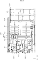
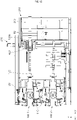
- the rewinding system 1 may include a rewinding apparatus 100 for winding a manufactured thin-film tape T (see FIG. 8 ) on re-winding rolls R1 and R2, a loading apparatus 200 for loading the re-winding rolls R1 and R2 on which the thin-film tape T is rewound, and a cutting apparatus 300 for cutting the thin-film tape T.
- a rewinding apparatus 100 for winding a manufactured thin-film tape T see FIG. 8
- a loading apparatus 200 for loading the re-winding rolls R1 and R2 on which the thin-film tape T is rewound
- a cutting apparatus 300 for cutting the thin-film tape T.
- the rewinding system 1 may further include a plurality of rewinding apparatuses 100.
- the rewinding system 1 may include a first rewinding apparatus 100-1 and a second rewinding apparatus 100-2.
- first rewinding apparatus 100-1 and the second rewinding apparatus 100-2 may be disposed vertically with respect to each other and may move independently.
- the first rewinding apparatus 100-1 and the second rewinding apparatus 100-2 have the same structure, and thus, for convenience of description, the following description will focus on one rewinding apparatus 100.
- the rewinding system 1 may include a processor 30 and a memory 40.
- the processor 30 may be included in the rewinding system 1 to perform overall control of the rewinding system 1.
- the processor 30 may be connected to the rewinding apparatus 100, the loading apparatus 200, the cutting apparatus 300, and the loading guide apparatus 400 to control the respective apparatuses. That is, the operations and controls of the respective apparatuses, which will be described below, may be performed by the processor 30.
- the processor 30 may include a central processing unit (CPU), a controller, an application processor (AP), or one or more of a communication processor (CP) and an ARM processor.
- CPU central processing unit
- AP application processor
- CP communication processor
- ARM ARM processor
- the memory 40 is embedded in the rewinding system 1 and may be configured as a memory. Specifically, the memory 40 may be implemented as at least one of a flash memory type, ROM, RAM, a hard disk type, a multimedia card micro type, a card type memory (e.g., SD or XD memory, etc.).
- a flash memory type e.g., ROM, RAM, a hard disk type, a multimedia card micro type, a card type memory (e.g., SD or XD memory, etc.).
- the memory 40 may store a user's preset operation of the rewinding system 1 to store the operations and control processes of the rewinding system 1.
- the rewinding system 1 may include a sensor (not shown) for measuring the plurality of re-winding rolls R1 and R2. Accordingly, by comparing the data value measured by the sensor with the data values stored in the memory 40, the defective state of the thin-film tape T wound on the plurality of re-winding rolls R1 and R2 can be checked in real time. That is, the rewinding system 1 may perform real-time vision inspection on the thin-film tape T by means of the sensor (not shown).
- the rewinding apparatus 100 may include a first mounting member 110 a second mounting member 120 into which a plurality of re-winding rolls R1 and R2 are inserted, and a connecting member 130 connected to an end 110a of the first mounting member 110 and an end 120a of the second mounting member 120 to move the first mounting member 110 and the second mounting member 120.
- the rewinding apparatus 100 may include a plurality of mounting members 110 and 120 on which a plurality of re-winding rolls R1 and R2 on which the thin-film tape T may be wound at the same time are mounted.
- first mounting member 110 a plurality of first re-winding rolls R1 are mounted at a predetermined interval, and a plurality of thin-film tapes T may be simultaneously wound on the mounted plurality of first re-winding rolls R1.
- the rewinding process speed can be increased.
- the plurality of second re-winding rolls R2 may be mounted at a preset interval.
- first mounting member 110 and the second mounting member 120 may have the same shape, but the first mounting member 120 and the second mounting member 120 may be disposed at different positions.
- first mounting member 110 and the second mounting member 120 may be disposed parallel to each other.
- first mounting member 110 and the second mounting member 120 may independently move and rotate by means of the connecting member 130.
- first mounting member 110 may rotate about a shaft X1 of the first mounting member 110
- second mounting member 120 may independently rotate about a shaft X2 of the second mounting member 120.
- the second mounting member 120 may be in a non-rotating state.
- a user can selectively rewind the plurality of thin-film tapes T by selectively rotating the first mounting member 110 and the second mounting member 120.
- the connecting member 130 may be connected to the first mounting member 110 and the second mounting member 120 to independently rotate the first mounting member 110 and the second mounting member 120, and may independently move the first mounting member 110 and the second mounting member 120.
- the connecting member 130 may rotate the first mounting member 110 and the second mounting member 120 to change the positions of the first mounting member 110 and the second mounting member 120, and may move at least one of the first mounting member 110 and the second mounting member 120 to the place where the loading apparatus 220 is arranged.
- the connecting member 130 may include a rotation plate 131, and a first interlocking member 134-1 and a second interlocking member 134-2 connected to one surface 131a of the rotation plate 131 to independently rotate and move the first mounting member 110 and the second mounting member 120, respectively.
- one mounting member may be connected to one interlocking member.
- an end 110a of the first mounting member 110 is connected to the first interlocking member 134-1
- an end 120a of the second mounting member 120 is connected to the second interlocking member 134-2.
- the rotation plate 131 that is connected to the first interlocking member 134-1 and the second interlocking member 134-2 rotates in a preset direction C1 on a side surface 130a of the connecting member, the positions of the first mounting member 110 and the second mounting member 120 may be interchanged.
- the rotation plate 131 may be located on the side surface 130a of the connecting member, and may be parallel to the YZ plane.
- the first interlocking member 134-1 and the second interlocking member 134-2 have the same structure, and thus, for convenience of description, the following description will focus on one interlocking member.
- the second interlocking member 134-2 may include a rotation member 132 that rotates the second mounting member 120 about the shaft X2 of the second mounting member 120, and shaft moving members 133 disposed at both ends of the rotation member 132 so as to be perpendicular to the shaft X2 to move and rotate the rotation member 132 in the horizontal direction (XY plane).
- the second mounting member 120 can rotate about the shaft X2 of the second mounting member 120 through the rotating member 132, and can be moved on the XY plane through the shaft moving members 133.
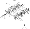
- FIG. 4 is a perspective view showing a cutting apparatus 300 according to an embodiment of the present disclosure.
- FIG. 5 is a top enlarged view showing the cutting apparatus 300 according to an embodiment of the present disclosure.
- FIG. 6 is a bottom enlarged view showing the cutting apparatus 300 according to an embodiment of the present disclosure.
- the cutting apparatus 300 is disposed on the first mounting member 110 or the second mounting member 120 to be rewound, and can cut the rewound thin-film tape T.
- the cutting apparatus 300 may have a plurality of multi-joint members 302 arranged at a preset interval on one reference shaft 301, and a plurality of cutting members 303 may be arranged at one end of each of the multi-joint members 302.
- the number of the cutting members 303 may correspond to the number of the plurality of re-winding rolls R1 and R2. Accordingly, one cutting member 303 may cut the thin-film tape T of one of the re-winding rolls R1 and R2.
- cutting apparatus 300 may rotate about the reference shaft 301, and accordingly, a roller part 310 may be selectively brought into contact with the thin-film tape T wound on the plurality of re-winding rolls R1 and R2.
- the cutting apparatus 300 may include: a roller part 310 for rolling the outer circumferential surface of the thin-film tape T wound on the re-winding rolls R1 and R2; an adsorption part 320 for vacuum-adsorbing the thin-film tape T rolled by the roller part 310; a fixing part 330 for selectively fixing the thin-film tape T adsorbed to the adsorption part 320; and a blade that slidably moves so as to be adjacent to one surface 320a of the adsorption part 320 in order to cut the thin-film tape T.
- the roller part 310 corresponding to a rear of the cutting member 303, is located behind the adsorption part 320 and the blade 340, and may be composed of a rotatable roll.
- the rear of the cutting member 303 means a place adjacent to the reference shaft 301 of the cutting apparatus 300.
- the roller part 310 is in contact with one re-winding roll R1 to continuously press the thin-film tape T wound on the re-winding roll R1, and may prevent a space in the thin-film tape T wound on the re-winding roll R1 from occurring.
- the roller part 310 may continuously contact the thin-film tape T wound on the first re-winding roll R1 and thus may press the thin-film tape T in the direction of the rotation center of the first mounting member 110.
- the roller part 310 continuously contacts the thin-film tape T wound on the second re-winding roll R2 to press the thin-film tape T in the direction of the rotation center of the second mounting member 120.
- the roller part 310 may allow thin-film tapes T wound on the re-winding roll R1 to be in close contact with each other, and may prevent lifting from occurring between the thin-film tapes T wound on the re-winding roll R1, thereby reducing manufacturing tolerances.
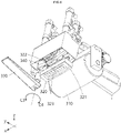
- the adsorption part 320 may include a contact portion 321 in contact with the thin-film tape T, and an adsorption space 322 stepped with respect to the contact portion 321 to adsorb and fix one surface of the thin-film tape T.
- the adsorption part 320 does not continuously contact the thin-film tape T, but selectively adsorbs the thin-film tape T when the thin-film tape T needs to be cut to adsorb the thin-film tape T to then fix the same to the adsorption part 320.
- the contact portion 321 may come into contact with one surface of the thin-film tape T, and the adsorption space 322 may form a pressurized space in which the air may be adsorbed through a suction port 323 formed in the adsorption space 322 to adsorb the thin-film tape T.
- the width of the contact portion 321 may be equal to or greater than the width of the thin-film tape T, and the width of the adsorption space 322 may be equal to or smaller than the width of the thin-film tape T. Accordingly, the entire thin-film tape T can be prevented from being rolled into the adsorption space 322.
- the contact portion 321 may be disposed on the outer peripheral surface of the adsorption space 322, and the adsorption space 322 may be formed to be stepped to form a space with respect to the contact portion 321.
- the suction port 323 may be disposed at a position facing one surface of the thin-film tape T, and the number thereof may vary in consideration of the pressure at which the thin-film tape T can be properly adsorbed.
- the adsorption part 320 may be disposed in front of the roller part 310.
- the front may mean a place far from the reference shaft 301.
- the fixing part 330 may axially rotate with respect to the adsorption part 320, and may selectively cover one surface of the adsorption space 322 and the contact portion 321.
- the fixing part 330 may move between a spaced-apart state from the adsorption part 330, as shown in FIG. 6 , and a fixed state in which the upper surface thereof is in contact with the lower surface of the thin-film tape T being in contact with the contact portion 321, as shown in FIG. 10 , thereby selectively completely fixing the thin-film tape T.
- the adsorption part 320 may adsorb the thin-film tape T.
- the upper surface of the thin-film tape T is in contact with the adsorption part 320.
- the fixing part 330 in a state in which the fixing part 330 axially moves in the direction C4 in which the absorption part 320 is located, the fixing part 330 closely moves with respect to the absorption part 320, so that the fixing part 330 is brought into contact with the lower surface of the thin-film tape T.
- the upper surface of the thin-film tape T is in contact with the adsorption part 320, and the lower surface of the thin-film tape T is in contact with the fixing part 330, thereby cutting the thin-film tape T by means of the blade 340 after being completely fixed to the cutting apparatus 300.
- the fixing part 330 may axially move in the direction C3 spaced apart from the adsorption part 320 again to be spaced apart from the adsorption part 320.
- the blade 340 slidably moves on the thin-film tape T fixed by the fixing part 330 and the adsorption part 320 to cut the thin-film tape T.
- the blade may have various shapes, but at least may have a width greater than the width of the thin-film tape T.
- FIG. 7 is a perspective view showing a loading guide apparatus 400 according to an embodiment of the present disclosure.
- the loading guide apparatus 400 may be disposed between the rewinding apparatus 100 and the loading apparatus 200, and may be arranged to connect at least one of the first mounting member 110 having moved adjacent to the loading apparatus 200 and the second mounting member 120.
- the loading guide apparatus 400 may include: a support part 420 for supporting the other end 110b or 120b (see FIG. 12 ) of at least one of the first mounting member 110 and the second mounting member 120 having moved adjacent to the loading apparatus 200 to horizontally maintain the other end of at least one of the first mounting member and the second mounting member; and a guide moving part 410 for adjusting the horizontality of the other end 110b or 120b of at least one of the first mounting member 110 and the second mounting member 120 having moved adjacent to the loading apparatus 200 by vertically and horizontally moving the support part 420.
- the loading guide apparatus 400 is connected to a rail part 20 (see FIG. 1 ) together with the rewinding apparatus 100 to move relative to each other.
- the guide moving part 410 may move in the horizontal direction along the rail part 20 and may move the support part 420 in the vertical direction.
- the guide moving part 410 moves so as to allow the support part 420 to support the mounting member of the first and second mounting members 110 and 120, which has moved adjacent to the loading apparatus 200 in the horizontal direction.
- the guide moving part 410 may move the support part 420 up and down to horizontally align the mounting members connected to the two rewinding apparatuses 100.
- the support part 420 may be moved in the vertical direction by the guide moving part 410, and may support the other end of the mounting member inclined by the weight of the plurality of re-winding rolls R1 and R2.
- the guide plate 430 may be disposed on one surface of the support part 420, and may push the plurality of re-winding rolls R1 and R2 to the loading apparatus 200.
- the guide plate 430 may extend with respect to the support part 420, and thus the plurality of re-winding rolls R1 and R2 are brought into contact with the side surfaces of the plurality of re-winding rolls R1 and R2, thereby moving the plurality of re-winding rolls R1 and R2 along the mounting member.
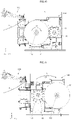
- FIG. 8 is a side view illustrating the rewinding apparatus 100 according to an embodiment of the present disclosure
- FIG. 9 is a side view showing the operation of the cutting apparatus 300 in the state of FIG. 8
- FIG. 10 is a side view illustrating a state in which a thin-film tape T is cut in the state shown in FIG. 9
- FIG. 11 is a side view illustrating that the positions of the first and second mounting members 110 and 120 are changed in the state shown in FIG. 10 .
- the first mounting member 110 may be axially rotated in a preset direction C2 to wind the manufactured thin-film tape T on the first re-winding roll R1.
- the rotation member 132 connected to the first mounting member 110 may rotate the first mounting member 110 about the rotation shaft of the first mounting member 110.
- the outer peripheral surface of the first re-winding roll R1 may be in continuous contact with the roller part 310 of the cutting apparatus 300.
- the rewinding apparatus 100 moves in a direction M1 adjacent to the loading apparatus 200.
- the adsorption part 320 of the cutting apparatus 300 may adsorb the thin-film tape T. Accordingly, as shown in FIG. 9 , a portion of the thin-film tape T may be in contact with the adsorption part 320 of the cutting apparatus 300.
- the thin-film tape T is cut by the blade 340.
- a portion of the cut thin-film tape T is in a state of being flowed down by its own weight, and the rewinding apparatus 100 further rotates a part of the first mounting member 110, thereby automatically winding the thin-film tape T having flowed down by its own weight on the first re-winding roll R1.
- the rewinding apparatus 100 rotates the rotation plate 131 in the C1 direction, thereby changing the positions of the first mounting member 110 and the second mounting member 120.
- the position of the first mounting member 110 and the position of the second mounting member 120 are changed, thereby rewinding the thin-film tape T on the second mounting member 120.
- the rewinding process speed and efficiency of the rewinding system 1 may be greatly improved.
- FIG. 11 shows that the positions of the first mounting member 110 and the second mounting member 120 are changed after the thin-film tape T is rewound on the plurality of re-winding rolls R1 inserted into the first mounting member 110, which may mean a third state.
- the rewinding apparatus 100 rotates the first mounting member 110 and the second mounting member 110 in the same direction C1 as the direction C2 in which the first mounting member 110 rotates about the shaft of the first mounting member 110, thereby changing the positions of the first mounting member 110 and the second mounting member 120.
- the process lines and the dynamic profiles do not overlap between the rewinding operations of the first mounting member 110 and the second mounting member 120 and the operations of changing the positions of the first mounting member 110 and the second mounting member 120 through rotation in the same direction, thereby improving the efficiency of the manufacturing process.
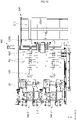
- FIG. 12 is a side view illustrating a first state in the rewinding system 1 according to an embodiment of the present disclosure
- FIG. 13 is a side view showing the movement of the loading guide apparatus 400 in the state shown in FIG. 12
- FIGS. 14 and 15 are side views illustrating that the loading guide apparatus 400 guides a plurality of re-winding rolls R2 to the loading apparatus in the state shown in FIG. 13 .
- the rewinding system 1 may move the second mounting member 120 into which the plurality of rewinding second re-winding rolls R2 are inserted to a place where the loading apparatus 200 is located.
- the second mounting member 120 may move to a place adjacent to the loading apparatus 200 along the XY plane by the shaft moving member 133 shown in FIG. 3 .
- the second mounting member 120 on which the rewinding is completed may move to load the plurality of second re-winding rolls R2.
- the other end 120b thereof is partially lowered by the weight of the plurality of second re-winding rolls R2, so that the second mounting member 120 and the loading member 210 of the loading apparatus 200 are in a state in which they are not aligned with each other.
- the loading member 210 may be provided in the loading apparatus 200, and at least one other end 110b, 120b of the first mounting member 110 and the second mounting member 120 may be inserted thereinto.
- the support part 420 may be moved to align the other end 120b of the second mounting member 120 with the loading member 210.
- the support part 420 may guide the plurality of re-winding rolls R1 and R2) to be pushed in the direction in which the loading member 210 is located.
- the plurality of re-winding rolls R1 and R2 on which the thin-film tape T is rewound may be loaded side by side on the loading member 210.
- the rewinding system 1 may move the second mounting member 120 back to a place adjacent to the first mounting member 110.
- the rewinding system 1 may repeatedly operate: a first state in which, while the thin-film tape T is being rewound on the plurality of re-winding rolls R1 inserted into the first mounting member 110, the second mounting member 120 into which the plurality of re-winding rolls R2 on which the thin-film tape T is rewound is moved to a place where the loading apparatus 200 is located; a second state in which, after the plurality of re-winding rolls R2 on which the thin-film tape T inserted into the second mounting member 120 is rewound is loaded in the loading apparatus 200, the second mounting member 120 is moved back to a place adjacent to the first mounting member 110; a third state in which, after the thin-film tape T is rewound on the plurality of re-winding rolls R1 inserted into the first mounting member 110, the positions of the first mounting member 110 and the second mounting member 120 are changed; a fourth state in which, while the thin-film tape T is being rewound on
- the second mounting member 120 on which the rewinding is completed may perform a loading operation
- the first mounting member 110 on which the rewinding is completed may perform a loading operation
- the rewinding system 1 rotates the first mounting member and the second mounting member 120 on its own, and automatically and continuously rewinds and loads the thin-film tape T through the configurations and operations for changing the positions of the first mounting member and the second mounting member 120, thereby greatly improving the efficiency of the rewinding process of the thin-film tape T.
Landscapes
- Replacement Of Web Rolls (AREA)
Abstract
Description
- The present disclosure relates to a rewinding system having improved process efficiency.
- With the development and demand for slim and small electronic devices, such as smart phones, tablets, laptops, and the like, thin-film tapes for various purposes, such as adhesion, insulation, and electrical connection between components in each electronic device are being used.
- Thin-film tapes being manufactured are manufactured in a primary form of being wound on a roll. However, each electronic device needs to be processed to the size and length required according to the manufacturing process thereof, and a secondary processing for winding the thin-film tapes on a new roll is required.
- Recently, a rewinding apparatus for newly winding a manufactured thin-film tape according to the needs of users and processes is used. In addition, the manufacturing efficiency of the entire process, including secondary processing, varies according to the process efficiency of a rewinding apparatus, and thus the efficiency of a rewinding apparatus for newly winding a manufactured thin-film tape is quite important the efficiency of a rewinding apparatus for newly winding a manufactured thin-film tape is quite important.
- The purpose of the present disclosure is to provide a rewinding system having improved process efficiency.
- The present disclosure for achieving the above purpose provides a rewinding system, comprising: a rewinding apparatus for winding a manufactured thin-film tape on a re-winding roll; a loading apparatus for loading the re-winding roll on which the thin-film tape is rewound; and a cutting apparatus for cutting the thin-film tape, wherein: the rewinding apparatus comprises a first mounting member and a second mounting member in which a plurality of re-winding rolls are inserted, and a connecting member connected to an end of the first mounting member and an end of the second mounting member to move the first mounting member and the second mounting member; the first mounting member rotates around a shaft thereof, and the second mounting member rotates around a shaft thereof; and the connecting member rotates the first mounting member and the second mounting member to change positions of the first mounting member and the second mounting member, and moves at least one of the first mounting member and the second mounting member to the place where the loading apparatus is arranged.
- The connecting member may include a rotation plate, and a first interlocking member and a second interlocking member connected to the rotating plate and one surface of the rotating plate to independently rotate and move the first and second mounting members, respectively, and the first interlocking member includes a rotation member for rotating the first mounting member about the shaft of the first mounting member, and shaft moving members disposed at both ends of the rotation member to be perpendicular to the shaft of the first mounting member to move the rotation member in the horizontal direction.
- The rewinding apparatus may repeatedly operate: a first state in which, while the thin-film tape is being rewound on the plurality of re-winding rolls inserted into the first mounting member, the second mounting member into which the plurality of re-winding rolls on which the thin-film tape is rewound is moved to a place where the loading apparatus is located; a second state in which, after the plurality of re-winding rolls on which the thin-film tape inserted into the second mounting member is rewound is loaded in the loading apparatus, the second mounting member is moved back to a place adjacent to the first mounting member; a third state in which, after the thin-film tape is rewound on the plurality of re-winding rolls inserted into the first mounting member, the positions of the first mounting member and the second mounting member are changed; a fourth state in which, while the thin-film tape is being rewound on the plurality of re-winding rolls inserted into the second mounting member, the first mounting member into which the plurality of re-winding rolls on which the thin-film tape is rewound are inserted is moved to a place where the loading apparatus is located; and a fifth state in which, after the plurality of re-winding rolls on which the thin-film tape inserted into the first mounting member is rewound are loaded in the loading apparatus, the first mounting member is moved back to a place adjacent to the second mounting member.
- The cutting apparatus may include a roller part, disposed on the first mounting member or the second mounting member to be rewound, for rolling an outer circumferential surface of the thin-film tape wound on the re-winding roll, an adsorption part for vacuum-adsorbing the tape rolled by the roller part, a fixing part for selectively fixing the thin-film tape adsorbed to the adsorption part, and a blade that slidably moves so as to be adjacent to one surface of the adsorption part in order to cut the thin-film tape.
- The adsorption part may include a contact portion being in contact with the thin-film tape, and an adsorption space that is stepped with respect to the contact portion and adsorbs and fixes one surface of the thin-film tape, and the fixing part may move between a spaced-apart state from the adsorption part and a fixed state in which the upper surface thereof is in contact with the lower surface of the thin-film tape being in contact with the contact portion.
- The rewinding system may further include a loading guide apparatus disposed between the rewinding apparatus and the loading apparatus and arranged to connect the loading apparatus with at least one of the first and second mounting members having moved adjacent to the loading apparatus, wherein the loading guide apparatus comprises: a support part for supporting the other end of at least one of the first mounting member and the second mounting member having moved adjacent to the loading apparatus to horizontally maintain the other end of at least one of the first mounting member and the second mounting member; and a guide moving part for adjusting the horizontality of the other end of at least one of the first mounting member and the second mounting member having moved adjacent to the loading apparatus by vertically and horizontally moving the support part.
- The loading apparatus may include a loading member into which the other end of at least one of the first mounting member and the second mounting member can be inserted, wherein, in a state in which the other end of at least one of the first mounting member and the second mounting member is inserted and connected to the loading member, the support part guides the plurality of re-winding rolls on which the thin-film tape is rewound to be pushed in a direction in which the loading member is located.
- The rewinding apparatus may rotate the first mounting member and the second mounting member in the same direction as a direction in which the first mounting member rotates about the shaft of the first mounting member to change the positions of the first mounting member and the second mounting member.
- The rewinding apparatus may further include a rail part connected to upper and lower sides thereof to horizontally move the rewinding apparatus.
-
-
FIG. 1 is a perspective view showing a rewinding system according to an embodiment of the present disclosure. -
FIG. 2 is a perspective view illustrating a rewinding apparatus according to an embodiment of the present disclosure. -
FIG. 3 is an enlarged view illustrating a region A ofFIG. 2 . -
FIG. 4 is a perspective view showing a cutting apparatus according to an embodiment of the present disclosure. -
FIG. 5 is a top enlarged view showing the cutting apparatus according to an embodiment of the present disclosure. -
FIG. 6 is a bottom enlarged view showing the cutting apparatus according to an embodiment of the present disclosure. -
FIG. 7 is a perspective view showing a loading guide apparatus according to an embodiment of the present disclosure. -
FIG. 8 is a side view illustrating the rewinding apparatus according to an embodiment of the present disclosure. -
FIG. 9 is a side view showing the operation of the cutting apparatus in the state ofFIG. 8 . -
FIG. 10 is a side view illustrating a state in which a thin-film tape is cut in the state shown inFIG. 9 . -
FIG. 11 is a side view illustrating that the positions of the first and second mounting members are changed in the state shown inFIG. 10 . -
FIG. 12 is a side view illustrating a first state in the rewinding system according to an embodiment of the present disclosure. -
FIG. 13 is a side view showing the movement of the loading guide apparatus in the state shown inFIG. 12 . -
FIGS. 14 and15 are side views illustrating that the loading guide apparatus guides a plurality of re-winding rolls to the loading apparatus in the state shown inFIG. 13 . - In order to fully understand the configuration and effect of the present disclosure, preferred embodiments of the present disclosure will be described with reference to the accompanying drawings. However, the present disclosure is not limited to the embodiments disclosed below, and may be implemented in various forms and various changes may be made. However, the description of the present embodiments is provided so that the disclosure of the present disclosure is complete, and to fully inform those of ordinary skill in the art to which the present disclosure belongs, the scope of the invention. In the accompanying drawings, for convenience of explanation, sizes of various components are enlarged exaggerated the components are enlarged from actuality, and the proportions of the respective components may be exaggerated or reduced.
- It will be understood that when an element is referred to as being "on" or "adjacent to" another element, another element may be directly abutting on or connected to the other element, but another element may be present therebetween. However, it will be understood that when an element is referred to as being "directly on" or "in direct contact with" another component, another element may not be present therebetween. Other expressions describing the relationship between elements, for example, "between" and "directly between", etc. may be interpreted similarly.
- It will be understood that, although the terms first, second, etc. may be used herein to describe various members, elements, regions, layers and/or sections, these members, elements, regions, layers and/or sections should not be limited by these terms. These terms are only used to distinguish one member, element, region, layer and/or section from another. Thus, for example, a first member, a first element, a first region, a first layer and/or a first section discussed below could be termed a second member, a second element, a second region, a second layer and/or a second section without departing from the teachings of the present disclosure.
- The singular expression includes the plural expression unless the context clearly dictates otherwise. Terms such as "comprises" or "have" are intended to designate that a feature, number, step, action, component, part, or combination thereof described in the specification exists, and may be construed as being capable of adding one or more other features or numbers, steps, operations, components, parts, or combinations thereof.
- Unless otherwise defined, terms used in the embodiments of the present disclosure may be interpreted as meanings commonly known to a person skilled in the art.
- Hereinafter, a rewinding system 1 and a rewinding
apparatus 100, according to an embodiment of the present disclosure, will be described with reference toFIGS. 1 to 3 . -
FIG. 1 is a perspective view showing a rewinding system 1 according to an embodiment of the present disclosure.FIG. 2 is a perspective view illustrating a rewindingapparatus 100 according to an embodiment of the present disclosure.FIG. 3 is an enlarged view illustrating a region A ofFIG. 2 . - The rewinding system 1 may wind a manufactured thin-film tape on a new roll according to the needs of users and processes and load the rewound roll into a loading apparatus at the same time.
- Specifically, the rewinding system 1 may include a rewinding
apparatus 100 for winding a manufactured thin-film tape T (seeFIG. 8 ) on re-winding rolls R1 and R2, aloading apparatus 200 for loading the re-winding rolls R1 and R2 on which the thin-film tape T is rewound, and acutting apparatus 300 for cutting the thin-film tape T. - Here, the rewinding system 1 may further include a plurality of rewinding
apparatuses 100. For example, referring toFIG. 12 , the rewinding system 1 may include a first rewinding apparatus 100-1 and a second rewinding apparatus 100-2. - However, the first rewinding apparatus 100-1 and the second rewinding apparatus 100-2 may be disposed vertically with respect to each other and may move independently. The first rewinding apparatus 100-1 and the second rewinding apparatus 100-2 have the same structure, and thus, for convenience of description, the following description will focus on one rewinding
apparatus 100. - In addition, the rewinding system 1 may include a
processor 30 and amemory 40. Theprocessor 30 may be included in the rewinding system 1 to perform overall control of the rewinding system 1. For example, theprocessor 30 may be connected to the rewindingapparatus 100, theloading apparatus 200, thecutting apparatus 300, and theloading guide apparatus 400 to control the respective apparatuses. That is, the operations and controls of the respective apparatuses, which will be described below, may be performed by theprocessor 30. - Here, the
processor 30 may include a central processing unit (CPU), a controller, an application processor (AP), or one or more of a communication processor (CP) and an ARM processor. - The
memory 40 is embedded in the rewinding system 1 and may be configured as a memory. Specifically, thememory 40 may be implemented as at least one of a flash memory type, ROM, RAM, a hard disk type, a multimedia card micro type, a card type memory (e.g., SD or XD memory, etc.). - Accordingly, the
memory 40 may store a user's preset operation of the rewinding system 1 to store the operations and control processes of the rewinding system 1. - In addition, the rewinding system 1 may include a sensor (not shown) for measuring the plurality of re-winding rolls R1 and R2. Accordingly, by comparing the data value measured by the sensor with the data values stored in the
memory 40, the defective state of the thin-film tape T wound on the plurality of re-winding rolls R1 and R2 can be checked in real time. That is, the rewinding system 1 may perform real-time vision inspection on the thin-film tape T by means of the sensor (not shown). - Referring to
FIGS. 2 and3 , therewinding apparatus 100 may include a first mountingmember 110 a second mountingmember 120 into which a plurality of re-winding rolls R1 and R2 are inserted, and a connectingmember 130 connected to anend 110a of the first mountingmember 110 and anend 120a of the second mountingmember 120 to move the first mountingmember 110 and the second mountingmember 120. - The
rewinding apparatus 100 may include a plurality of mountingmembers - For example, in the first mounting
member 110, a plurality of first re-winding rolls R1 are mounted at a predetermined interval, and a plurality of thin-film tapes T may be simultaneously wound on the mounted plurality of first re-winding rolls R1. - Accordingly, since the plurality of thin-film tapes T may be rewound through the plurality of first re-winding rolls R1 mounted on the first mounting
member 110, instead of one re-winding roll, the rewinding process speed can be increased. - Similarly, in the second mounting
member 120, the plurality of second re-winding rolls R2 may be mounted at a preset interval. - Here, the first mounting
member 110 and the second mountingmember 120 may have the same shape, but the first mountingmember 120 and the second mountingmember 120 may be disposed at different positions. - For example, the first mounting
member 110 and the second mountingmember 120 may be disposed parallel to each other. - In addition, the first mounting
member 110 and the second mountingmember 120 may independently move and rotate by means of the connectingmember 130. - For example, the first mounting
member 110 may rotate about a shaft X1 of the first mountingmember 110, and the second mountingmember 120 may independently rotate about a shaft X2 of the second mountingmember 120. - Specifically, while the plurality of thin-film tapes T are wound on the plurality of first re-winding rolls R1 mounted on the first mounting
member 110 by rotating the first mountingmember 110, the second mountingmember 120 may be in a non-rotating state. - Accordingly, a user can selectively rewind the plurality of thin-film tapes T by selectively rotating the first mounting
member 110 and the second mountingmember 120. - The connecting
member 130 may be connected to the first mountingmember 110 and the second mountingmember 120 to independently rotate the first mountingmember 110 and the second mountingmember 120, and may independently move the first mountingmember 110 and the second mountingmember 120. - In addition, the connecting
member 130 may rotate the first mountingmember 110 and the second mountingmember 120 to change the positions of the first mountingmember 110 and the second mountingmember 120, and may move at least one of the first mountingmember 110 and the second mountingmember 120 to the place where the loading apparatus 220 is arranged. - Specifically, the connecting
member 130 may include arotation plate 131, and a first interlocking member 134-1 and a second interlocking member 134-2 connected to onesurface 131a of therotation plate 131 to independently rotate and move the first mountingmember 110 and the second mountingmember 120, respectively. - That is, one mounting member may be connected to one interlocking member. For example, an
end 110a of the first mountingmember 110 is connected to the first interlocking member 134-1, and anend 120a of the second mountingmember 120 is connected to the second interlocking member 134-2. - Accordingly, as the
rotation plate 131 that is connected to the first interlocking member 134-1 and the second interlocking member 134-2 rotates in a preset direction C1 on aside surface 130a of the connecting member, the positions of the first mountingmember 110 and the second mountingmember 120 may be interchanged. - Here, the
rotation plate 131 may be located on theside surface 130a of the connecting member, and may be parallel to the YZ plane. - The first interlocking member 134-1 and the second interlocking member 134-2 have the same structure, and thus, for convenience of description, the following description will focus on one interlocking member.
- The second interlocking member 134-2 may include a
rotation member 132 that rotates the second mountingmember 120 about the shaft X2 of the second mountingmember 120, andshaft moving members 133 disposed at both ends of therotation member 132 so as to be perpendicular to the shaft X2 to move and rotate therotation member 132 in the horizontal direction (XY plane). - Therefore, the second mounting
member 120 can rotate about the shaft X2 of the second mountingmember 120 through the rotatingmember 132, and can be moved on the XY plane through theshaft moving members 133. - Hereinafter, with reference to
FIGS. 4 to 6 , thecutting apparatus 300 according to an embodiment of the present disclosure will be described in detail. -
FIG. 4 is a perspective view showing acutting apparatus 300 according to an embodiment of the present disclosure.FIG. 5 is a top enlarged view showing thecutting apparatus 300 according to an embodiment of the present disclosure.FIG. 6 is a bottom enlarged view showing thecutting apparatus 300 according to an embodiment of the present disclosure. - Referring to
FIG. 1 , thecutting apparatus 300 is disposed on the first mountingmember 110 or the second mountingmember 120 to be rewound, and can cut the rewound thin-film tape T. - Referring to
FIG. 4 , thecutting apparatus 300 may have a plurality ofmulti-joint members 302 arranged at a preset interval on onereference shaft 301, and a plurality of cuttingmembers 303 may be arranged at one end of each of themulti-joint members 302. - Here, the number of the cutting
members 303 may correspond to the number of the plurality of re-winding rolls R1 and R2. Accordingly, one cuttingmember 303 may cut the thin-film tape T of one of the re-winding rolls R1 and R2. - In addition, cutting
apparatus 300 may rotate about thereference shaft 301, and accordingly, aroller part 310 may be selectively brought into contact with the thin-film tape T wound on the plurality of re-winding rolls R1 and R2. - The
cutting apparatus 300 may include: aroller part 310 for rolling the outer circumferential surface of the thin-film tape T wound on the re-winding rolls R1 and R2; anadsorption part 320 for vacuum-adsorbing the thin-film tape T rolled by theroller part 310; a fixingpart 330 for selectively fixing the thin-film tape T adsorbed to theadsorption part 320; and a blade that slidably moves so as to be adjacent to onesurface 320a of theadsorption part 320 in order to cut the thin-film tape T. - The
roller part 310, corresponding to a rear of the cuttingmember 303, is located behind theadsorption part 320 and the blade 340, and may be composed of a rotatable roll. - Here, the rear of the cutting
member 303 means a place adjacent to thereference shaft 301 of thecutting apparatus 300. - The
roller part 310 is in contact with one re-winding roll R1 to continuously press the thin-film tape T wound on the re-winding roll R1, and may prevent a space in the thin-film tape T wound on the re-winding roll R1 from occurring. - For example, as shown in
FIG. 8 , when the thin-film tape T is wound on the first re-winding roll R1 mounted on the first mountingmember 110 by rotating the first mountingmember 110 in a preset direction C2, theroller part 310 may continuously contact the thin-film tape T wound on the first re-winding roll R1 and thus may press the thin-film tape T in the direction of the rotation center of the first mountingmember 110. - Similarly, even when the positions of the first mounting
member 110 and the second mountingmember 120 are changed, the second mountingmember 120 is rotated in the preset direction C2, and the thin-film tape T is wound on the second re-winding roll R2 mounted on the second mountingmember 120, theroller part 310 continuously contacts the thin-film tape T wound on the second re-winding roll R2 to press the thin-film tape T in the direction of the rotation center of the second mountingmember 120. - Accordingly, the
roller part 310 may allow thin-film tapes T wound on the re-winding roll R1 to be in close contact with each other, and may prevent lifting from occurring between the thin-film tapes T wound on the re-winding roll R1, thereby reducing manufacturing tolerances. - The
adsorption part 320 may include acontact portion 321 in contact with the thin-film tape T, and anadsorption space 322 stepped with respect to thecontact portion 321 to adsorb and fix one surface of the thin-film tape T. - Here, the
adsorption part 320 does not continuously contact the thin-film tape T, but selectively adsorbs the thin-film tape T when the thin-film tape T needs to be cut to adsorb the thin-film tape T to then fix the same to theadsorption part 320. - The
contact portion 321 may come into contact with one surface of the thin-film tape T, and theadsorption space 322 may form a pressurized space in which the air may be adsorbed through asuction port 323 formed in theadsorption space 322 to adsorb the thin-film tape T. - The width of the
contact portion 321 may be equal to or greater than the width of the thin-film tape T, and the width of theadsorption space 322 may be equal to or smaller than the width of the thin-film tape T. Accordingly, the entire thin-film tape T can be prevented from being rolled into theadsorption space 322. - The
contact portion 321 may be disposed on the outer peripheral surface of theadsorption space 322, and theadsorption space 322 may be formed to be stepped to form a space with respect to thecontact portion 321. - The
suction port 323 may be disposed at a position facing one surface of the thin-film tape T, and the number thereof may vary in consideration of the pressure at which the thin-film tape T can be properly adsorbed. - The
adsorption part 320 may be disposed in front of theroller part 310. Here, the front may mean a place far from thereference shaft 301. - The fixing
part 330 may axially rotate with respect to theadsorption part 320, and may selectively cover one surface of theadsorption space 322 and thecontact portion 321. - For example, the fixing
part 330 may move between a spaced-apart state from theadsorption part 330, as shown inFIG. 6 , and a fixed state in which the upper surface thereof is in contact with the lower surface of the thin-film tape T being in contact with thecontact portion 321, as shown inFIG. 10 , thereby selectively completely fixing the thin-film tape T. - Specifically, as shown in
FIG. 6 , in a state in which the fixingpart 330 and theadsorption part 320 are spaced apart from each other, theadsorption part 320 may adsorb the thin-film tape T. Here, the upper surface of the thin-film tape T is in contact with theadsorption part 320. Next, in a state in which the fixingpart 330 axially moves in the direction C4 in which theabsorption part 320 is located, the fixingpart 330 closely moves with respect to theabsorption part 320, so that the fixingpart 330 is brought into contact with the lower surface of the thin-film tape T. - Accordingly, the upper surface of the thin-film tape T is in contact with the
adsorption part 320, and the lower surface of the thin-film tape T is in contact with the fixingpart 330, thereby cutting the thin-film tape T by means of the blade 340 after being completely fixed to thecutting apparatus 300. - After the thin-film tape T is cut, the fixing
part 330 may axially move in the direction C3 spaced apart from theadsorption part 320 again to be spaced apart from theadsorption part 320. - The blade 340 slidably moves on the thin-film tape T fixed by the fixing
part 330 and theadsorption part 320 to cut the thin-film tape T. The blade may have various shapes, but at least may have a width greater than the width of the thin-film tape T. - Hereinafter, a
loading guide apparatus 400 according to an embodiment of the present disclosure will be described with reference toFIG. 7 . -
FIG. 7 is a perspective view showing aloading guide apparatus 400 according to an embodiment of the present disclosure. - Referring to
FIGS. 1 and7 , theloading guide apparatus 400 may be disposed between the rewindingapparatus 100 and theloading apparatus 200, and may be arranged to connect at least one of the first mountingmember 110 having moved adjacent to theloading apparatus 200 and the second mountingmember 120. - In addition, the
loading guide apparatus 400 may include: asupport part 420 for supporting theother end 110b or 120b (seeFIG. 12 ) of at least one of the first mountingmember 110 and the second mountingmember 120 having moved adjacent to theloading apparatus 200 to horizontally maintain the other end of at least one of the first mounting member and the second mounting member; and aguide moving part 410 for adjusting the horizontality of theother end 110b or 120b of at least one of the first mountingmember 110 and the second mountingmember 120 having moved adjacent to theloading apparatus 200 by vertically and horizontally moving thesupport part 420. - In addition, the
loading guide apparatus 400 is connected to a rail part 20 (seeFIG. 1 ) together with therewinding apparatus 100 to move relative to each other. - The
guide moving part 410 may move in the horizontal direction along therail part 20 and may move thesupport part 420 in the vertical direction. - Accordingly, the
guide moving part 410 moves so as to allow thesupport part 420 to support the mounting member of the first and second mountingmembers loading apparatus 200 in the horizontal direction. - In addition, when a plurality of rewinding
apparatuses 100 are disposed, theguide moving part 410 may move thesupport part 420 up and down to horizontally align the mounting members connected to the two rewindingapparatuses 100. - The
support part 420 may be moved in the vertical direction by theguide moving part 410, and may support the other end of the mounting member inclined by the weight of the plurality of re-winding rolls R1 and R2. - The
guide plate 430 may be disposed on one surface of thesupport part 420, and may push the plurality of re-winding rolls R1 and R2 to theloading apparatus 200. Theguide plate 430 may extend with respect to thesupport part 420, and thus the plurality of re-winding rolls R1 and R2 are brought into contact with the side surfaces of the plurality of re-winding rolls R1 and R2, thereby moving the plurality of re-winding rolls R1 and R2 along the mounting member. - Hereinafter, the operation of the
rewinding apparatus 100 according to an embodiment of the present disclosure will be described with reference toFIGS. 8 to 11 . -
FIG. 8 is a side view illustrating therewinding apparatus 100 according to an embodiment of the present disclosure,FIG. 9 is a side view showing the operation of thecutting apparatus 300 in the state ofFIG. 8 ,FIG. 10 is a side view illustrating a state in which a thin-film tape T is cut in the state shown inFIG. 9 , andFIG. 11 is a side view illustrating that the positions of the first and second mountingmembers FIG. 10 . - First, as shown in
FIG. 8 , the first mountingmember 110 may be axially rotated in a preset direction C2 to wind the manufactured thin-film tape T on the first re-winding roll R1. - Specifically, the
rotation member 132 connected to the first mountingmember 110 may rotate the first mountingmember 110 about the rotation shaft of the first mountingmember 110. - Here, the outer peripheral surface of the first re-winding roll R1 may be in continuous contact with the
roller part 310 of thecutting apparatus 300. - Thereafter, after it is detected by means of a sensor (not shown) that the thin-film tape T is wound on the first re-winding roll R1 so as to have a predetermined outer diameter, the
rewinding apparatus 100 moves in a direction M1 adjacent to theloading apparatus 200. - Here, while the
rewinding apparatus 100 moves in the M1 direction, theadsorption part 320 of thecutting apparatus 300 may adsorb the thin-film tape T. Accordingly, as shown inFIG. 9 , a portion of the thin-film tape T may be in contact with theadsorption part 320 of thecutting apparatus 300. - That is, by partially moving the
rewinding apparatus 100 in the M1 direction, a region where the thin-film tape T is cut can be secured, thereby automatically and continuously performing the process of rewinding the thin-film tape T. - Next, as shown in
FIG. 10 , in a state in which the fixingpart 330 comes into contact with theadsorption part 320 to completely fix the thin-film tape T, the thin-film tape T is cut by the blade 340. - Here, a portion of the cut thin-film tape T is in a state of being flowed down by its own weight, and the
rewinding apparatus 100 further rotates a part of the first mountingmember 110, thereby automatically winding the thin-film tape T having flowed down by its own weight on the first re-winding roll R1. - Next, as shown in
FIG. 11 , therewinding apparatus 100 rotates therotation plate 131 in the C1 direction, thereby changing the positions of the first mountingmember 110 and the second mountingmember 120. - That is, after the thin-film tape T is completely wound on the first mounting
member 110, the position of the first mountingmember 110 and the position of the second mountingmember 120 are changed, thereby rewinding the thin-film tape T on the second mountingmember 120. - Accordingly, by sequentially performing the rewinding operations of the first mounting
member 110 and the second mountingmember 120 in that order, the rewinding process speed and efficiency of the rewinding system 1 may be greatly improved. - Here,
FIG. 11 shows that the positions of the first mountingmember 110 and the second mountingmember 120 are changed after the thin-film tape T is rewound on the plurality of re-winding rolls R1 inserted into the first mountingmember 110, which may mean a third state. - In addition, the
rewinding apparatus 100 rotates the first mountingmember 110 and the second mountingmember 110 in the same direction C1 as the direction C2 in which the first mountingmember 110 rotates about the shaft of the first mountingmember 110, thereby changing the positions of the first mountingmember 110 and the second mountingmember 120. - Accordingly, the process lines and the dynamic profiles do not overlap between the rewinding operations of the first mounting
member 110 and the second mountingmember 120 and the operations of changing the positions of the first mountingmember 110 and the second mountingmember 120 through rotation in the same direction, thereby improving the efficiency of the manufacturing process. - Hereinafter, a process in which the plurality of second re-winding rolls R2 on which the thin-film tape T is rewound is loaded in the
loading apparatus 200 will be described with reference toFIGS. 12 to 15 . -
FIG. 12 is a side view illustrating a first state in the rewinding system 1 according to an embodiment of the present disclosure,FIG. 13 is a side view showing the movement of theloading guide apparatus 400 in the state shown inFIG. 12 , andFIGS. 14 and15 are side views illustrating that theloading guide apparatus 400 guides a plurality of re-winding rolls R2 to the loading apparatus in the state shown inFIG. 13 . - Referring to
FIG. 12 , while the thin-film tape T is rewound on the plurality of first re-winding rolls R1 inserted into the first mountingmember 110, the rewinding system 1 may move the second mountingmember 120 into which the plurality of rewinding second re-winding rolls R2 are inserted to a place where theloading apparatus 200 is located. - Here, the second mounting
member 120 may move to a place adjacent to theloading apparatus 200 along the XY plane by theshaft moving member 133 shown inFIG. 3 . - That is, while the first mounting
member 110 rewinds the thin-film tape T, the second mountingmember 120 on which the rewinding is completed may move to load the plurality of second re-winding rolls R2. - Here, in the second mounting
member 120 having moved adjacent to theloading apparatus 200, theother end 120b thereof is partially lowered by the weight of the plurality of second re-winding rolls R2, so that the second mountingmember 120 and theloading member 210 of theloading apparatus 200 are in a state in which they are not aligned with each other. - Here, the
loading member 210 may be provided in theloading apparatus 200, and at least oneother end 110b, 120b of the first mountingmember 110 and the second mountingmember 120 may be inserted thereinto. - As shown in
FIG. 13 , after moving to a place adjacent to theother end 120b of the second mountingmember 120, thesupport part 420 may be moved to align theother end 120b of the second mountingmember 120 with theloading member 210. - Next, as shown in
FIGS. 14 and15 , in a state in which at least oneother end 110b, 120b of the first mountingmember 110 and the second mountingmember 120 is inserted into and connected to theloading member 210, the thin-film tape T is rewound in the connected state, thesupport part 420 may guide the plurality of re-winding rolls R1 and R2) to be pushed in the direction in which theloading member 210 is located. - Accordingly, the plurality of re-winding rolls R1 and R2 on which the thin-film tape T is rewound may be loaded side by side on the
loading member 210. - Next, after the plurality of re-winding rolls R2 on which the thin-film tape T inserted into the second mounting
member 120 is rewound are loaded in theloading apparatus 200, the rewinding system 1 may move the second mountingmember 120 back to a place adjacent to the first mountingmember 110. - That is, the rewinding system 1 may repeatedly operate: a first state in which, while the thin-film tape T is being rewound on the plurality of re-winding rolls R1 inserted into the first mounting member 110, the second mounting member 120 into which the plurality of re-winding rolls R2 on which the thin-film tape T is rewound is moved to a place where the loading apparatus 200 is located; a second state in which, after the plurality of re-winding rolls R2 on which the thin-film tape T inserted into the second mounting member 120 is rewound is loaded in the loading apparatus 200, the second mounting member 120 is moved back to a place adjacent to the first mounting member 110; a third state in which, after the thin-film tape T is rewound on the plurality of re-winding rolls R1 inserted into the first mounting member 110, the positions of the first mounting member 110 and the second mounting member 120 are changed; a fourth state in which, while the thin-film tape T is being rewound on the plurality of re-winding rolls R2 inserted into the second mounting member 120, the first mounting member 110 into which the plurality of re-winding rolls R1 on which the thin-film tape T is rewound are inserted is moved to a place where the loading apparatus 200 is located; and a fifth state in which, after the plurality of re-winding rolls R1 on which the thin-film tape T inserted into the first mounting member 110 is rewound are loaded in the loading apparatus 200, the first mounting member 110 is moved back to a place adjacent to the second mounting member 120.
- That is, in the aforementioned rewinding system 1, while the first mounting
member 110 performs rewinding, the second mountingmember 120 on which the rewinding is completed may perform a loading operation, and while the second mountingmember 120 performs rewinding, the first mountingmember 110 on which the rewinding is completed may perform a loading operation. - Accordingly, the rewinding system 1 rotates the first mounting member and the second mounting
member 120 on its own, and automatically and continuously rewinds and loads the thin-film tape T through the configurations and operations for changing the positions of the first mounting member and the second mountingmember 120, thereby greatly improving the efficiency of the rewinding process of the thin-film tape T. - While various embodiments of the present disclosure have been individually described, each embodiment is not necessarily implemented alone, and the configurations and operations of each embodiment may be implemented in combination with at least one of other embodiments.
- In addition, although preferred embodiments of the present disclosure have been illustrated and described above, the present disclosure is not limited to the specific embodiments described above, and the technical field to which the disclosure belongs without departing from the gist of the present disclosure as claimed in the claims, and these modifications should not be individually understood from the spirit or prospect of the present disclosure.
Claims (9)
- A rewinding system, comprising:a rewinding apparatus for winding a manufactured thin-film tape on a re-winding roll;a loading apparatus for loading the re-winding roll on which the thin-film tape is rewound; anda cutting apparatus for cutting the thin-film tape,wherein: the rewinding apparatus comprises a first mounting member and a second mounting member in which a plurality of re-winding rolls are inserted, and a connecting member connected to an end of the first mounting member and an end of the second mounting member to move the first mounting member and the second mounting member; the first mounting member rotates around a shaft thereof and the second mounting member rotates around a shaft thereof; and the connecting member rotates the first mounting member and the second mounting member to change positions of the first mounting member and the second mounting member, and moves at least one of the first mounting member and the second mounting member to the place where the loading apparatus is arranged.
- The rewinding system of claim 1, wherein the connecting member comprises:a rotation plate; anda first interlocking member and a second interlocking member connected to the rotating plate and one surface of the rotating plate to independently rotate and move the first and second mounting members, respectively, andthe first interlocking member comprises:a rotation member for rotating the first mounting member about the shaft of the first mounting member; andshaft moving members disposed at both ends of the rotation member to be perpendicular to the shaft of the first mounting member to move the rotation member in the horizontal direction.
- The rewinding system of claim 1, wherein the rewinding apparatus may repeatedly operate:a first state in which, while the thin-film tape is being rewound on the plurality of re-winding rolls inserted into the first mounting member, the second mounting member into which the plurality of re-winding rolls on which the thin-film tape is rewound is moved to a place where the loading apparatus is located;a second state in which, after the plurality of re-winding rolls on which the thin-film tape inserted into the second mounting member is rewound is loaded in the loading apparatus, the second mounting member is moved back to a place adjacent to the first mounting member;a third state in which, after the thin-film tape is rewound on the plurality of re-winding rolls inserted into the first mounting member, the positions of the first mounting member and the second mounting member are changed;a fourth state in which, while the thin-film tape is being rewound on the plurality of re-winding rolls inserted into the second mounting member, the first mounting member into which the plurality of re-winding rolls on which the thin-film tape is rewound are inserted is moved to a place where the loading apparatus is located; anda fifth state in which, after the plurality of re-winding rolls on which the thin-film tape inserted into the first mounting member is rewound are loaded in the loading apparatus, the first mounting member is moved back to a place adjacent to the second mounting member.
- The rewinding system of claim 1, wherein the cutting apparatus is disposed on the first mounting member or the second mounting member to be rewound, and comprises:a roller part for rolling an outer circumferential surface of the thin-film tape wound on the re-winding roll;an adsorption part for vacuum-adsorbing the tape rolled by the roller part;a fixing part for selectively fixing the thin-film tape adsorbed to the adsorption part; anda blade that slidably moves so as to be adjacent to one surface of the adsorption part in order to cut the thin-film tape.
- The rewinding system of claim 4, wherein the adsorption part comprises:a contact portion being in contact with the thin-film tape; andan adsorption space that is stepped with respect to the contact portion and adsorbs and fixes one surface of the thin-film tape, andthe fixing part moves between a spaced-apart state from the adsorption part and a fixed state in which the upper surface thereof is in contact with the lower surface of the thin-film tape being in contact with the contact portion.
- The rewinding system of claim 3, further comprising a loading guide apparatus disposed between the rewinding apparatus and the loading apparatus and arranged to connect the loading apparatus with at least one of the first and second mounting members having moved adjacent to the loading apparatus, wherein the loading guide apparatus comprises:a support part for supporting the other end of at least one of the first mounting member and the second mounting member having moved adjacent to the loading apparatus to horizontally maintain the other end of at least one of the first mounting member and the second mounting member; anda guide moving part for adjusting the horizontality of the other end of at least one of the first mounting member and the second mounting member having moved adjacent to the loading apparatus by vertically and horizontally moving the support part.
- The rewinding system of claim 6, wherein the loading apparatus comprises a loading member into which the other end of at least one of the first mounting member and the second mounting member can be inserted,
wherein, in a state in which the other end of at least one of the first mounting member and the second mounting member is inserted and connected to the loading member, the support part guides the plurality of re-winding rolls on which the thin-film tape is rewound to be pushed in a direction in which the loading member is located. - The rewinding system of claim 1, wherein the rewinding apparatus rotates the first mounting member and the second mounting member in the same direction as a direction in which the first mounting member rotates about the shaft of the first mounting member to change the positions of the first mounting member and the second mounting member.
- The rewinding system of claim 1, wherein the rewinding apparatus further comprises a rail part connected to upper and lower sides thereof to horizontally move the rewinding apparatus.
Applications Claiming Priority (2)
| Application Number | Priority Date | Filing Date | Title |
|---|---|---|---|
| KR1020200004994A KR102145059B1 (en) | 2020-01-14 | 2020-01-14 | Re-winding system |
| PCT/KR2020/016984 WO2021145556A1 (en) | 2020-01-14 | 2020-11-26 | Rewinding system |
Publications (3)
| Publication Number | Publication Date |
|---|---|
| EP4053057A1 true EP4053057A1 (en) | 2022-09-07 |
| EP4053057A4 EP4053057A4 (en) | 2024-09-11 |
| EP4053057B1 EP4053057B1 (en) | 2025-12-24 |
Family
ID=72449908
Family Applications (1)
| Application Number | Title | Priority Date | Filing Date |
|---|---|---|---|
| EP20914269.4A Active EP4053057B1 (en) | 2020-01-14 | 2020-11-26 | Rewinding system |
Country Status (6)
| Country | Link |
|---|---|
| US (1) | US12325604B2 (en) |
| EP (1) | EP4053057B1 (en) |
| KR (1) | KR102145059B1 (en) |
| CN (1) | CN114845947B (en) |
| PL (1) | PL4053057T3 (en) |
| WO (1) | WO2021145556A1 (en) |
Families Citing this family (2)
| Publication number | Priority date | Publication date | Assignee | Title |
|---|---|---|---|---|
| KR102145059B1 (en) | 2020-01-14 | 2020-09-02 | 주식회사 호건에프에이 | Re-winding system |
| CN117755875B (en) * | 2024-02-22 | 2024-05-14 | 广州雅策锐设备制造有限公司 | Rewinding and slitting device |
Family Cites Families (32)
| Publication number | Priority date | Publication date | Assignee | Title |
|---|---|---|---|---|
| US4529141A (en) * | 1984-01-13 | 1985-07-16 | Imd Corporation | Method and apparatus for rewinding, severing and transferring web-like material |
| US4909452A (en) * | 1988-02-29 | 1990-03-20 | Paper Converting Machine Company | Surface winder and method |
| JP2558535B2 (en) * | 1990-03-19 | 1996-11-27 | 株式会社片岡機械製作所 | Take-up roll take-out and core mounting device |
| US5810966A (en) * | 1994-12-08 | 1998-09-22 | Dai Nippon Printing Co., Ltd. | Sheet roll producing apparatus |
| DE19507799C2 (en) * | 1995-03-06 | 1997-04-30 | Kleinewefers Ramisch Gmbh | Device for the continuous winding of web-shaped material to be wound |
| KR0145960B1 (en) * | 1995-03-23 | 1998-08-17 | 도철기 | Winding method and device for insulation tape |
| US5845867A (en) * | 1997-10-10 | 1998-12-08 | The Black Clawson Company | Continuous winder |
| FI106785B (en) | 1999-06-10 | 2001-04-12 | Pesmel Oy | Arrangement and method for wrapping a piece |
| IT1321284B1 (en) * | 2000-06-05 | 2004-01-08 | Gd Spa | DEVICE FOR THE AUTOMATIC JOINTING OF TAPES CARRIED OUT BY REELS. |
| JP4452414B2 (en) * | 2001-02-14 | 2010-04-21 | 萩原工業株式会社 | Slitter take-up product carrying device |
| JP3962680B2 (en) * | 2002-12-09 | 2007-08-22 | 三菱重工業株式会社 | Paper passing bar and winder equipment |
| KR100554063B1 (en) * | 2004-02-09 | 2006-02-22 | 일진에이테크 주식회사 | Four winding device with double deck |
| JP2005320107A (en) * | 2004-05-07 | 2005-11-17 | Fuso Gosei Kk | Winder equipment |
| AT501926B1 (en) | 2005-05-30 | 2007-05-15 | Sml Maschinengesellschaft Mbh | DEVICE FOR ATTACHING AT LEAST TWO MATERIAL RAILS |
| KR100709945B1 (en) * | 2006-12-05 | 2007-04-25 | 고정수 | Vinyl winding device for paint cover |
| JP4922799B2 (en) * | 2007-03-16 | 2012-04-25 | 富士フイルム株式会社 | Web rewinding apparatus and method |
| KR100880394B1 (en) * | 2007-07-30 | 2009-01-30 | 주식회사 세일하이텍 | Film winding device with suction bar |
| US7631832B1 (en) | 2009-01-14 | 2009-12-15 | Chun-Tsai Chen | Packing film stretching and rewinding machine |
| KR101171173B1 (en) | 2011-01-27 | 2012-08-20 | 주식회사 신광엔지니어링 | Surface winder and winding method using the same |
| DE102011007092B4 (en) * | 2011-04-08 | 2019-02-14 | PSA Technology S.à.r.l. | Reverse drum winder for winding web-like materials into rolls |
| CN102259771B (en) | 2011-05-27 | 2013-06-19 | 广东仕诚塑料机械有限公司 | Winding device for plastic stretch film |
| KR101431784B1 (en) * | 2012-10-15 | 2014-08-19 | 주식회사 한라정밀엔지니어링 | Unit for anti-loose tape and Winder machine of the carrier having it |
| KR101443119B1 (en) | 2013-12-05 | 2014-09-30 | 엠에스티코리아(주) | apparatus for rewinding firm to be processed |
| KR101553167B1 (en) * | 2014-06-05 | 2015-09-15 | 한철근 | Automatic winder for film extrusion |
| WO2016002532A1 (en) | 2014-06-30 | 2016-01-07 | 株式会社瑞光 | Sheet delivery system and sheet delivery method using same |
| CN104444505A (en) | 2014-11-05 | 2015-03-25 | 苏州金纬机械制造有限公司 | Automatic sheet take-up device |
| DE102015208136A1 (en) | 2015-04-30 | 2016-11-03 | Krones Aktiengesellschaft | Method and device for conveying, providing and exchanging rolls of packaging material in a packaging machine |
| CN107032104B (en) * | 2016-02-04 | 2023-07-04 | 潮州市彩达包装机械有限公司 | Numerical control automatic discharging device of longitudinal dividing and cutting machine |
| FR3061488B1 (en) * | 2016-12-30 | 2019-05-17 | Sas Mondon | DEVICE FOR THE CONTINUOUS PRODUCTION OF WALLETS OF WOUND BANDS |
| FR3062807B1 (en) * | 2017-02-14 | 2019-03-15 | Spoolex | METHOD AND INSTALLATION FOR CONTINUOUS WRAPPING OF GUM STRIPS TO FORM GALETTES |
| CN108046019B (en) * | 2017-11-08 | 2019-12-24 | 中国科学院深圳先进技术研究院 | A kind of strip packing method |
| KR102145059B1 (en) * | 2020-01-14 | 2020-09-02 | 주식회사 호건에프에이 | Re-winding system |
-
2020
- 2020-01-14 KR KR1020200004994A patent/KR102145059B1/en active Active
- 2020-11-26 PL PL20914269.4T patent/PL4053057T3/en unknown
- 2020-11-26 US US17/785,159 patent/US12325604B2/en active Active
- 2020-11-26 CN CN202080089436.6A patent/CN114845947B/en active Active
- 2020-11-26 WO PCT/KR2020/016984 patent/WO2021145556A1/en not_active Ceased
- 2020-11-26 EP EP20914269.4A patent/EP4053057B1/en active Active
Also Published As
| Publication number | Publication date |
|---|---|
| US20230356971A1 (en) | 2023-11-09 |
| CN114845947A (en) | 2022-08-02 |
| EP4053057B1 (en) | 2025-12-24 |
| CN114845947B (en) | 2024-01-26 |
| EP4053057A4 (en) | 2024-09-11 |
| KR102145059B1 (en) | 2020-09-02 |
| PL4053057T3 (en) | 2026-04-27 |
| WO2021145556A1 (en) | 2021-07-22 |
| US12325604B2 (en) | 2025-06-10 |
Similar Documents
| Publication | Publication Date | Title |
|---|---|---|
| US12325604B2 (en) | Rewinding system | |
| KR101956930B1 (en) | Materials automatically exchanging device of secondary battery winding equipment | |
| CN102544592B (en) | Cascading device for electrode substrate | |
| CN117208624A (en) | Composite tape splicing and reel changing mechanism and tape splicing and reel changing method | |
| US8991738B2 (en) | Web winding apparatus | |
| CN219873659U (en) | Winding device | |
| CN114014076A (en) | Slitting and winding turret | |
| CN102195226A (en) | Cable supplying and rotating system | |
| CN111960155A (en) | Automatic tape splicing device and unreeling device with same | |
| WO2024140309A1 (en) | Tape wrapping device | |
| CN223409061U (en) | Coil replacing device and winding equipment | |
| JP2005259531A (en) | Manufacturing device of flat electronic parts | |
| KR20230123372A (en) | Secondary battery manufacturing apparatus and secondary battery manufacturing method using the same | |
| CN102544568B (en) | Laminating device for electrode base | |
| CN116613369B (en) | Electrode assembly and cell head winding method | |
| CN221777156U (en) | Roll changing device | |
| CN112404165B (en) | Material tape rewinding device | |
| WO2025112991A1 (en) | Winding and unwinding apparatus and processing system | |
| KR20240176887A (en) | Apparatus for Unwinding Electrode Sheet | |
| CN222947779U (en) | A material roll switching device and winding equipment | |
| CN115172897A (en) | Composite pole piece winding equipment | |
| CN210795178U (en) | Winding device | |
| CN208905248U (en) | A kind of flexible PCB automatic chip mounting device | |
| CN208916372U (en) | A coil uncoiler conveying equipment | |
| CN218448061U (en) | Rewinding splitting equipment |
Legal Events
| Date | Code | Title | Description |
|---|---|---|---|
| STAA | Information on the status of an ep patent application or granted ep patent |
Free format text: STATUS: THE INTERNATIONAL PUBLICATION HAS BEEN MADE |
|
| PUAI | Public reference made under article 153(3) epc to a published international application that has entered the european phase |
Free format text: ORIGINAL CODE: 0009012 |
|
| STAA | Information on the status of an ep patent application or granted ep patent |
Free format text: STATUS: REQUEST FOR EXAMINATION WAS MADE |
|
| 17P | Request for examination filed |
Effective date: 20220531 |
|
| AK | Designated contracting states |
Kind code of ref document: A1 Designated state(s): AL AT BE BG CH CY CZ DE DK EE ES FI FR GB GR HR HU IE IS IT LI LT LU LV MC MK MT NL NO PL PT RO RS SE SI SK SM TR |
|
| DAV | Request for validation of the european patent (deleted) | ||
| DAX | Request for extension of the european patent (deleted) | ||
| A4 | Supplementary search report drawn up and despatched |
Effective date: 20240809 |
|
| RIC1 | Information provided on ipc code assigned before grant |
Ipc: B65H 18/10 20060101ALI20240805BHEP Ipc: B65H 19/22 20060101ALI20240805BHEP Ipc: B65H 19/26 20060101ALI20240805BHEP Ipc: B65H 19/18 20060101AFI20240805BHEP |
|
| RAP1 | Party data changed (applicant data changed or rights of an application transferred) |
Owner name: SAMSUNG SDI CO., LTD. Owner name: EDS CO., LTD |
|
| GRAP | Despatch of communication of intention to grant a patent |
Free format text: ORIGINAL CODE: EPIDOSNIGR1 |
|
| STAA | Information on the status of an ep patent application or granted ep patent |
Free format text: STATUS: GRANT OF PATENT IS INTENDED |
|
| INTG | Intention to grant announced |
Effective date: 20250918 |
|
| GRAS | Grant fee paid |
Free format text: ORIGINAL CODE: EPIDOSNIGR3 |
|
| GRAA | (expected) grant |
Free format text: ORIGINAL CODE: 0009210 |
|
| STAA | Information on the status of an ep patent application or granted ep patent |
Free format text: STATUS: THE PATENT HAS BEEN GRANTED |
|
| AK | Designated contracting states |
Kind code of ref document: B1 Designated state(s): AL AT BE BG CH CY CZ DE DK EE ES FI FR GB GR HR HU IE IS IT LI LT LU LV MC MK MT NL NO PL PT RO RS SE SI SK SM TR |
|
| REG | Reference to a national code |
Ref country code: CH Ref legal event code: F10 Free format text: ST27 STATUS EVENT CODE: U-0-0-F10-F00 (AS PROVIDED BY THE NATIONAL OFFICE) Effective date: 20251224 Ref country code: GB Ref legal event code: FG4D |
|
| REG | Reference to a national code |
Ref country code: DE Ref legal event code: R096 Ref document number: 602020064572 Country of ref document: DE |
|
| REG | Reference to a national code |
Ref country code: LT Ref legal event code: MG9D |
|
| PG25 | Lapsed in a contracting state [announced via postgrant information from national office to epo] |
Ref country code: NO Free format text: LAPSE BECAUSE OF FAILURE TO SUBMIT A TRANSLATION OF THE DESCRIPTION OR TO PAY THE FEE WITHIN THE PRESCRIBED TIME-LIMIT Effective date: 20260324 |
|
| PG25 | Lapsed in a contracting state [announced via postgrant information from national office to epo] |
Ref country code: FI Free format text: LAPSE BECAUSE OF FAILURE TO SUBMIT A TRANSLATION OF THE DESCRIPTION OR TO PAY THE FEE WITHIN THE PRESCRIBED TIME-LIMIT Effective date: 20251224 Ref country code: HR Free format text: LAPSE BECAUSE OF FAILURE TO SUBMIT A TRANSLATION OF THE DESCRIPTION OR TO PAY THE FEE WITHIN THE PRESCRIBED TIME-LIMIT Effective date: 20251224 |
|
| PG25 | Lapsed in a contracting state [announced via postgrant information from national office to epo] |
Ref country code: RS Free format text: LAPSE BECAUSE OF FAILURE TO SUBMIT A TRANSLATION OF THE DESCRIPTION OR TO PAY THE FEE WITHIN THE PRESCRIBED TIME-LIMIT Effective date: 20260324 |
|
| PG25 | Lapsed in a contracting state [announced via postgrant information from national office to epo] |
Ref country code: LV Free format text: LAPSE BECAUSE OF FAILURE TO SUBMIT A TRANSLATION OF THE DESCRIPTION OR TO PAY THE FEE WITHIN THE PRESCRIBED TIME-LIMIT Effective date: 20251224 |
|
| REG | Reference to a national code |
Ref country code: NL Ref legal event code: MP Effective date: 20251224 |
|
| PG25 | Lapsed in a contracting state [announced via postgrant information from national office to epo] |
Ref country code: BG Free format text: LAPSE BECAUSE OF FAILURE TO SUBMIT A TRANSLATION OF THE DESCRIPTION OR TO PAY THE FEE WITHIN THE PRESCRIBED TIME-LIMIT Effective date: 20251224 |